1. Introduction
The natural draft hybrid cooling (NDHC) technology is proposed to address the performance deterioration of the power plant with natural draft dry cooling (NDDC) during hot weather, and to reduce the large amount of water consumption of the natural draft wet cooling (NDWC) [
1,
2,
3]. The nexus between electricity consumption and water protection attracts more studies [
4]. There are two design forms of NDHC, (1) air passes through wet and dry sections separately, mixing and flowing to the outlet [
5], and (2) air flows through dry/wet sections after wet/dry sections [
6]. These two forms are corresponding to the airside in serial and parallel heat exchange.
Wet-assisted dry cooling is one of the most common designs for airside in serial heat exchange [
7]. The air temperature is cooled by evaporative spray [
8] or water deluge [
9,
10,
11] during hot weather, and the heat transfer rate of the whole system is hence enhanced. He [
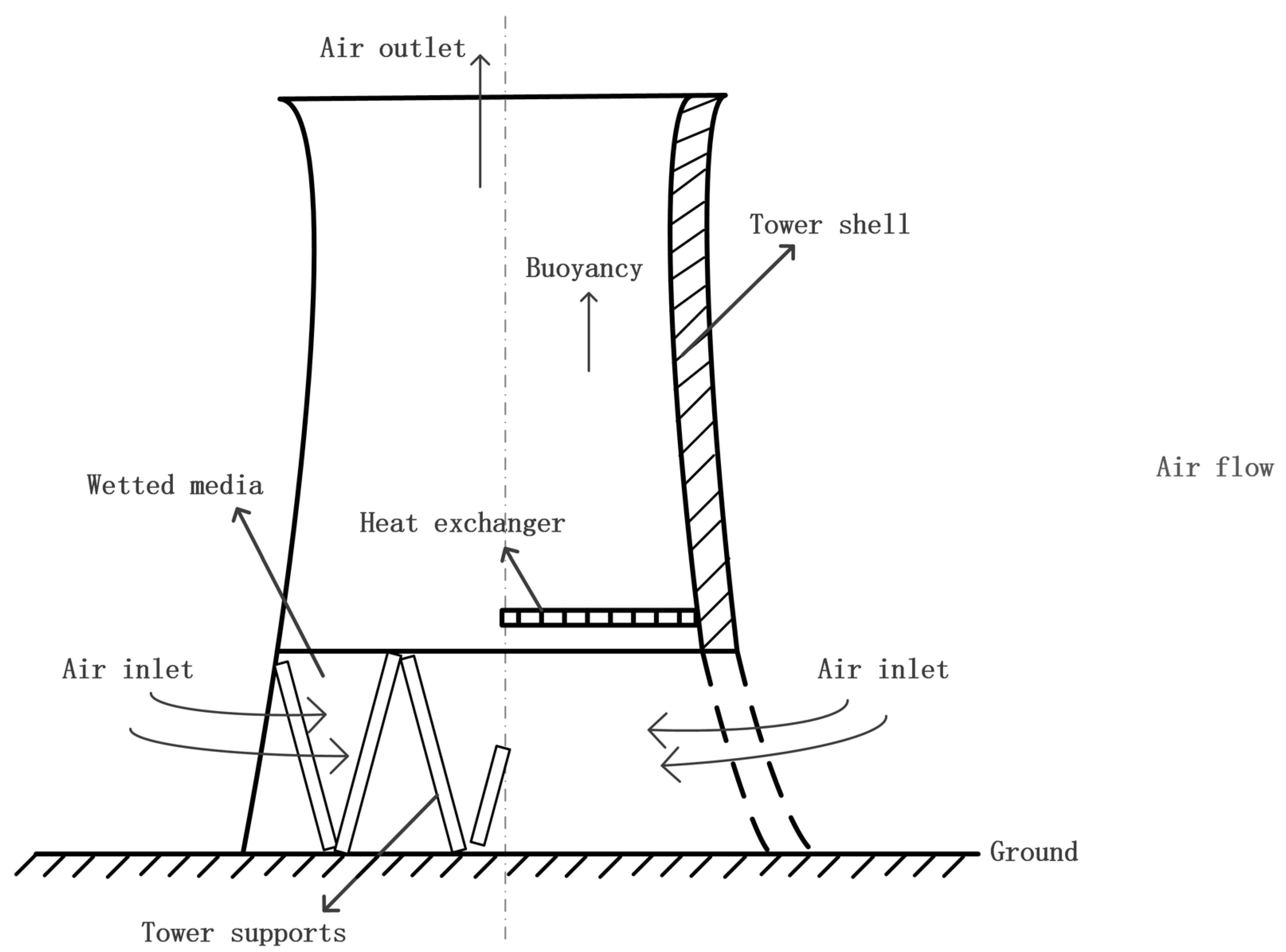
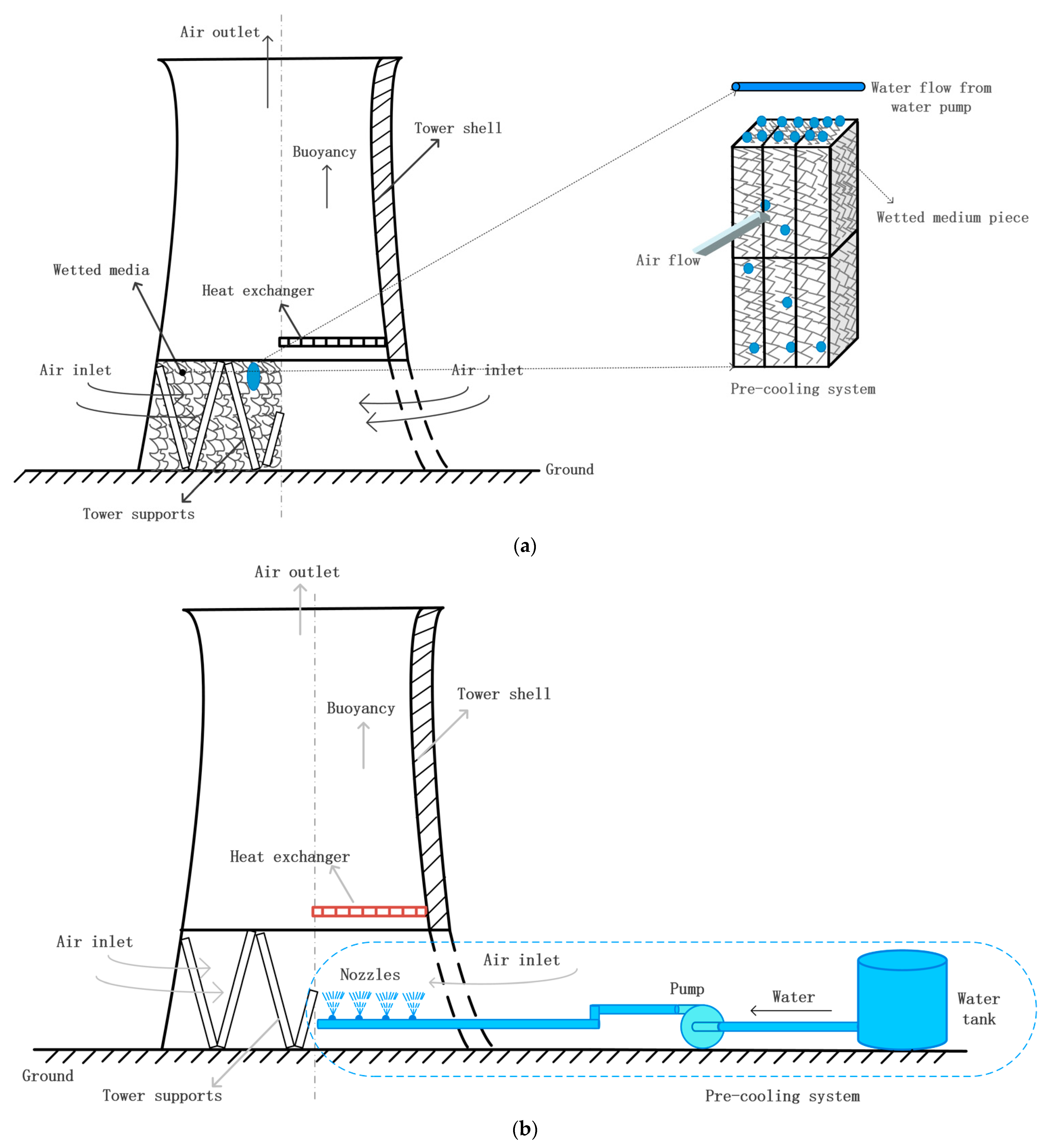
12] reported that it brings an extra 5% heat rejection rate with an assumption of 100% saturation efficiency on the inlet air. It is noted that the process of air making contact with water and being saturated requires relatively large transfer areas or droplets of small sizes [
13]. Then high-pressure nozzles [
14,
15] or alternative devices like fill [
16] are needed, as shown in
Figure 1.
The performance of pre-cooling with nozzles is mainly determined by spray areas, the possible parameters that affect spray areas are explored by numerical [
18,
19,
20,
21] or experiments [
22,
23]. The cooling efficiency of NDDC improves by about 2.5% after optimization of the nozzles arrangement. Packing fills usually adopted in NDWC can improve the performance further. However, unfavorable effects may be induced by fills during weather with low temperature and/or high humidity. To maintain adequate cooling capacity, inspired by the plume abated cooling tower, a re-construction of NDWC is proposed by the present author [
5]. Packing fill was located at the inlet cross-section of the tower. Temperature difference drives cooling air flowing through the packing fill and heat exchangers successively. The results showed that 70% heat flux of NDWC can be achieved by the new design with 50% water consumption of NDWC.
As for the parallel heat exchange type, such a structure will drive more airflow into the tower when compared with other designs because of the expanded inlet areas. The up limit of heat transfer rate for parallel heat exchange type is corresponding to the separate circuit hybrid cooling system, individual NDDC, and NDWC namely. The results showed that 90% heat flux of NDWC can be achieved by the separate type with 30% water consumption of NDWC [
24]. The higher capital cost promoted a highly integrated design. Heat exchangers and wet sections are arranged into a single tower. The airflow passes through the wet section and heat exchangers at the same time. Due to the complicated airside flow path and interactions between the waterside inlet and outlet of both dry and wet sections, the first attempt was conducted on a simplified model of the wet section [
25], generating the whole rain zone at the bottom of the heat exchangers. Compared to the packing fill, the mass transfer efficiency in this type was much lower. The results showed the cold air from the wet section led to a decrease in the temperature between the inside and outside tower, deteriorating the thermos-flow performances of NDHC in some conditions, even worse than NDDC. NDHC in the parallel heat exchange type with packing fill was simulated in 1D [
26]. The complicated airside flow of each section was connected by the uniform pressure in the mixed section. After that, a 3D model of the design was developed by Huang [
27]. These two models were in better agreement with the experimental results compared to the original model [
28]. Both the results above showed heat transfer rate in the wet section could cover the decrease of buoyancy forces in the dry section.
Results from existing studies showed that each heat exchange mode of NDHC consumes less water per MW than NDWC, providing the great potential to achieve cost-effective cooling for arid areas with hybrid cooling. A cooling system design is a compromise between the consumption of water and its cooling capacity. The highest heat transfer rate is not related to the optimal design [
29,
30]. There still lacks a comprehensive comparison of the water/energy nexus of all the four systems under the same conditions, NDDC/NDWC/NDHC in serial and parallel heat exchange designs. The performances are easily affected by variations in ambient conditions and marketing factors, like temperature, humidity, and unit cost of coal and water, exacerbating the complexity further.
In this study, with full consideration of each subunit, a thermal cycle of a power generating unit coupled with different cooling systems is simulated. The trade-off between water consumption and heat transfer is converted to the efficiency of the power plant. For the first time, a comparative analysis of the annual thermal performances of the cooling system itself, as well as the annual economic performances of the whole system is conducted to explore the applicability of the two hybrid cooling modes.
2. Mathematical Models
2.1. Heat Transfer Model of Dry Section
Heat exchangers of the dry section adopted a design with enhanced heat transfer surface area, including slotted aluminum plate finned tubes. There are three heat transfer processes for such a cross-flow heat exchange type:
- (1)
Water transfers heat to the inside wall of the tube.
The heat transfer coefficient inside a turbulent pipe can be described with the following Equation [
31],
where
f is the friction factor,
Then waterside heat transfer characteristics can be obtained,
- (2)
Heat conduction between the tube wall of inside and outside.
Due to the very thin wall of the tube and the relatively high coefficient of heat conduction of aluminum, this section can be ignored to save computing time.
- (3)
The airflow is heated by the tube.
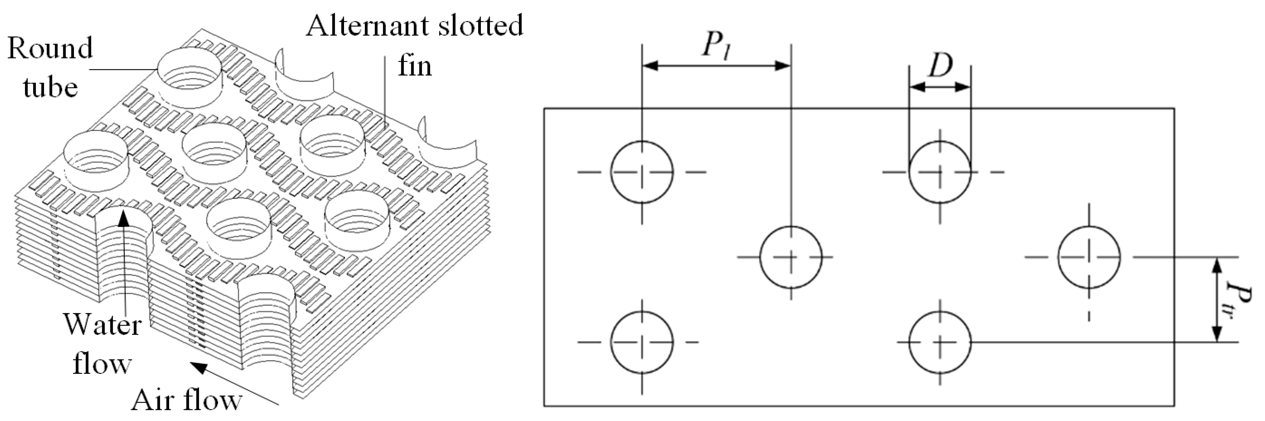
The airside heat transfer coefficient with detailed design in
Figure 2 can be obtained by a wind tunnel experiment with a different frontal velocity of air. The detailed experiment setup can be seen in our previous work [
32].
Then the total heat transfer rate of the dry section has the following form,
where
FT is the correction factor for crossflow, and the total heat transfer rate is defined as,
The control equations for energy balance are analyzed for water and air,
With Equations (4) and (6), the operation parameters are obtained with known mass flow rate and inlet temperature of water and air.
2.2. Heat and Mass Transfer Model of Wet Section
The detailed structures of the wet section are shown in
Figure 3. The areas can be divided into three zones, water spray before flowing into fills, fills, and dropped into basin. The heat and mass transfer for the rain zone is developed based on the Sherwood number of a single droplet by de Villiers [
33],
where
Sh is Sherwood number.
As for the spray zone and fill zone, fills expand the heat and mass transfer areas, as well as the short path of the spray zone, making it too complicated to obtain an analytical solution. The mass transfer performance for fills and spray zone adopt the correlations from Kröger’s experiment [
34],
where
G and
a represent mass velocity and area divided by the volume.
Merkel number can be obtained by experiments,
For the whole wet section, a numerical calculation can be conducted with the help of the four-point form of the Chebyshev integral regardless of the detailed zones [
35],
The control equations for energy balance are analyzed for water and air,
With Equations (10)–(12), the operation parameters of the wet section are obtained with known mass flow rate and inlet temperature of water and air.
2.3. Draft Balance of Dry and Wet Section
The loss induced by the fill and heat exchanger has the following form,
For the dry section, losses consist of contraction (
kctc), expansion (
kcte), and the core areas (
kheθ),
As for wet sections [
34],
where detailed losses represent rain zone,
krz, fill,
kfi, separation, and redirection,
kct, spray zone,
ksp, and drift eliminator,
kde, respectively.
That is to say, the mass flow rate of air can be determined by the pressure and temperature of the outlet air.
2.4. Cooling Systems
2.4.1. NDDC
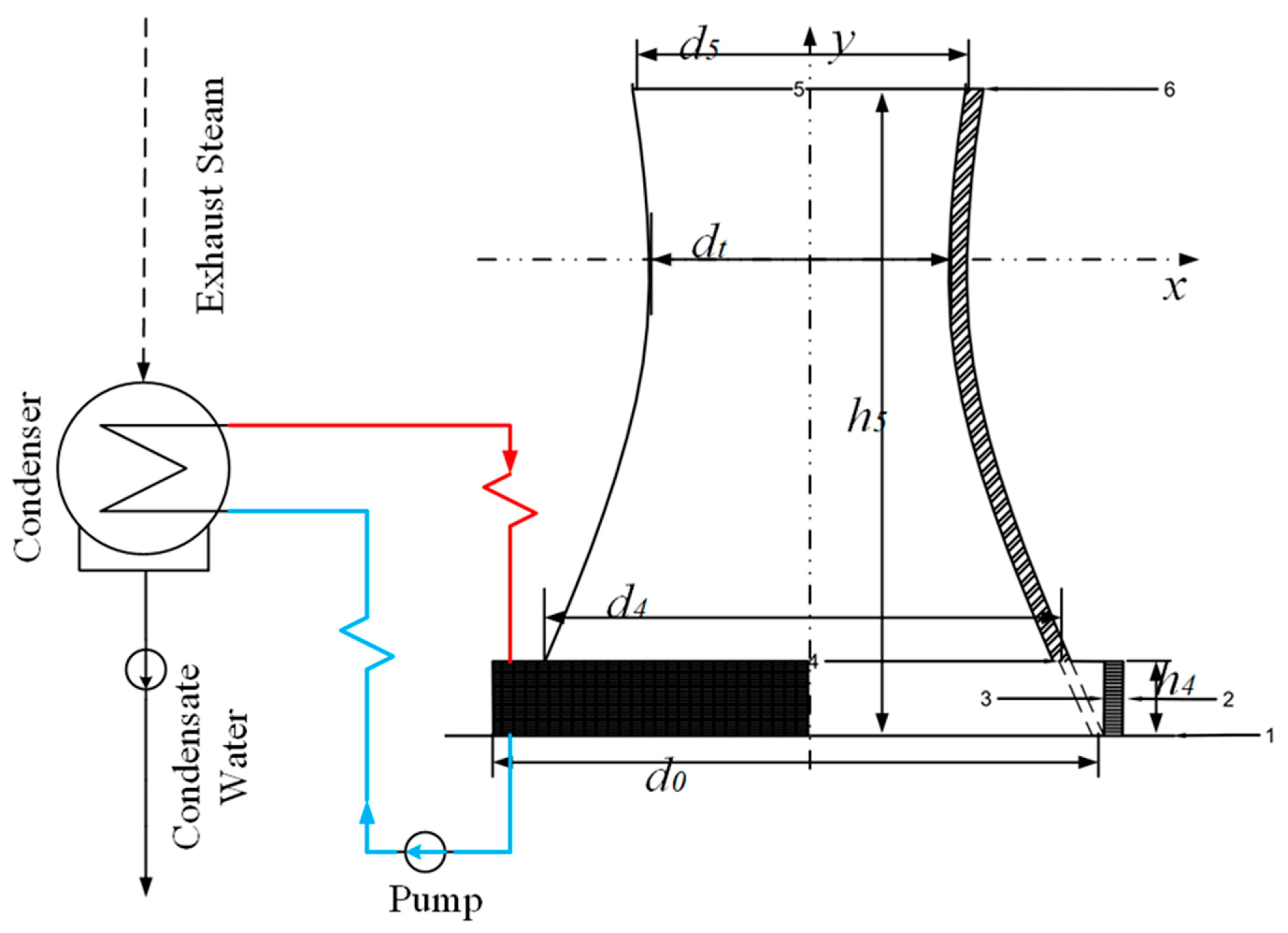
The flow path of NDDC can be seen in
Figure 4, positions airflow passes through are noted with numbers from 1-6. Red lines and blue lines mean the hot and cold water. Air density difference induced by the vertical heat exchange bundles with the form of
Figure 2 drives air flow into the tower, from 1–2–3. Thus, the airflow along the tower shell can be regarded as adiabatic, and the pressure difference along with height from 4–5 is calculated by [
34],
The loss coefficient of a cylindrical outlet from 5–6 is expressed as [
36],
where
.
The outlet air pressure of the dry section is obtained with the known outlet air temperature of the dry section. With Equations (4), (6), (14), (16) and (17), the performance of NDDCs can be solved.
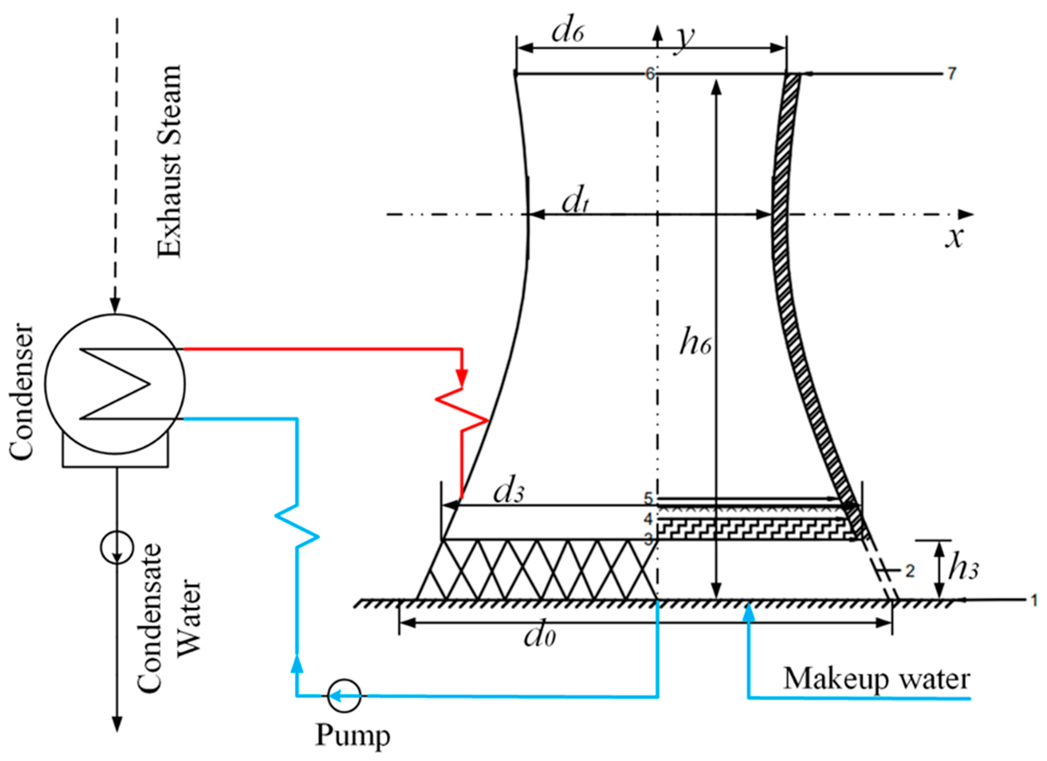
2.4.2. NDWC
Airflow along NDWC is also driven by the density difference before and after heat transfer devices, and fills horizontally arranged inside the tower. The diagram of NDWC is shown in
Figure 5. Numbers and colors noted on the figure have similar meaning with
Figure 4. However, the rising of moist air is regarded as a pseudo-adiabatic process but not adiabatic [
36],
where
ξTa5 is the lapse rate [
35],
Frd is similar to NDDC,
The outlet air pressure of the wet section is obtained with known outlet air temperature and humidity of the wet section. With Equations (10)–(12), (15), (18) and (19), the performance of NDWC can be obtained.
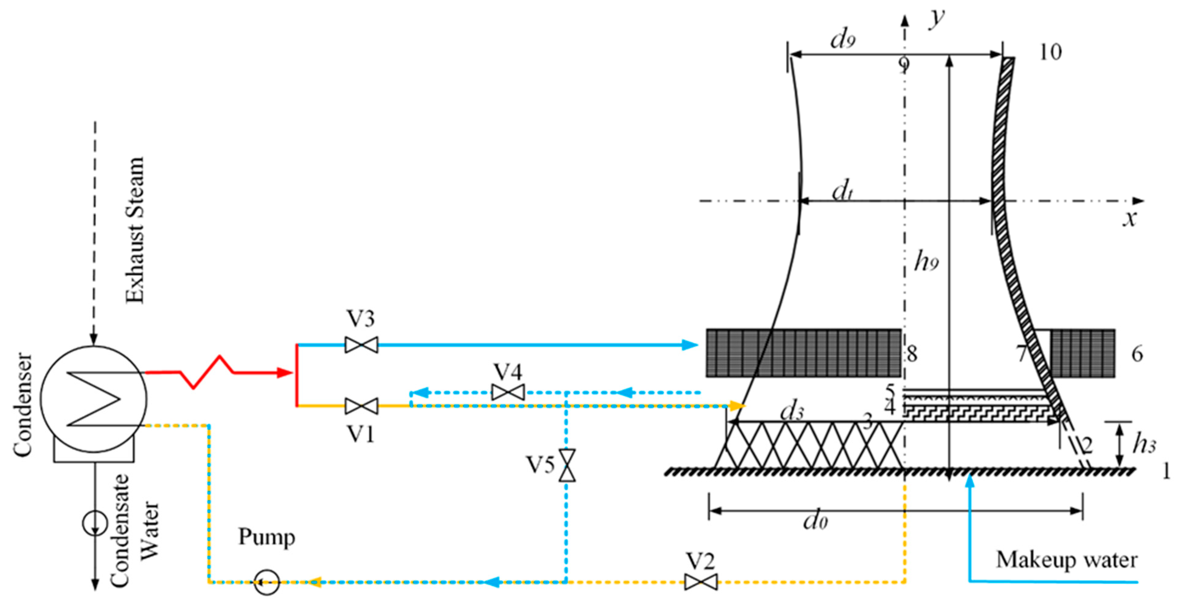
2.4.3. NDHC
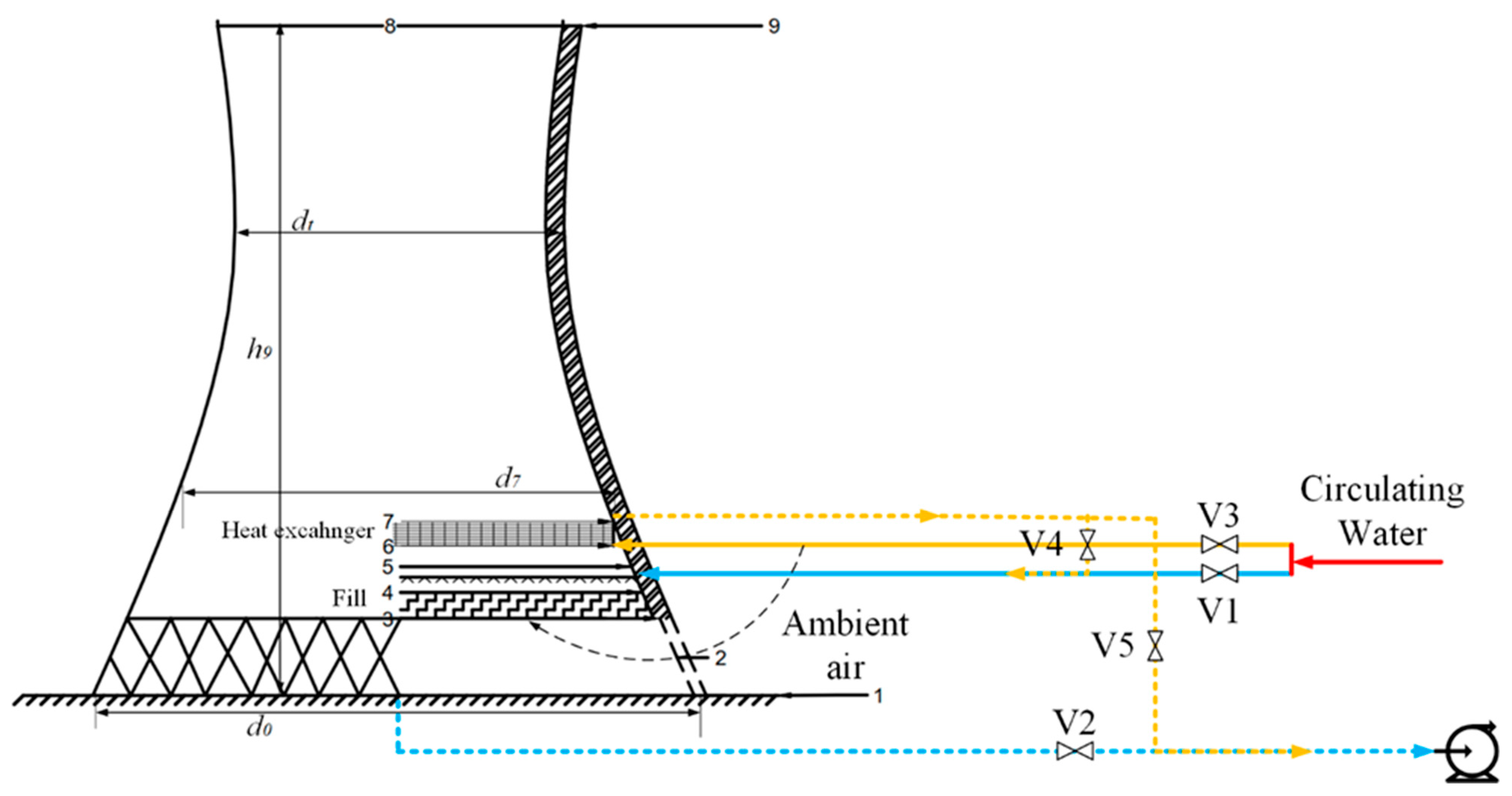
There are two types of design of hybrid cooling, differentiating in the view of airflow: parallel design represents the air flows from heat exchanger bundles and fills simultaneously (as shown in
Figure 6) and one after another (as shown in
Figure 7). The waterflow of two hybrid cooling designs can be both controlled with the help of electro valves as noted with V1–V5. Numbers noted on the
Figure 6 and
Figure 7 are physical positions of the air passes, detailed parameters can be seen in tables of
Section 3.
Take the parallel design to illustrate how the waterflow switch works: V3 opens and closes V1, the hot water from the condenser flows into the dry section first. V2, V4, and V5 are used to determine whether the system is operated in hybrid mode (V5 close with V2 and V4 open) or pure dry mode (V5 open with V2 and V4 close). Other modes can also be achieved with a similar control strategy. Red lines represent the hot water from condenser. Yellow and blue lines are wet and dry section, and the solid and dash lines are hot water and cold water for each part respectively.
The calculation of the dry section and wet section is the same as the individual equations in the previous sections. Air from the two different sections can be regarded as mass-based average when flows into the mixed part,
The process from the mixed section to the outlet of the system is described as [
36],
The connection between the dry section and wet section of NDHC in parallel design is the well-mixed of pressure.
As for the serial exchange mode, besides the individual calculation of the wet and dry section, the connection exists that the airside mass flow rate of the wet section equals that of the dry section.
Then, the performance of NDHC can be solved. Another notable difference between the two designs are dry section, the NDHC in parallel design and NDHC in serial design will be simplified as NDHCV (with vertical heat exchangers) and NDHCV (with vertical heat exchangers) to avoid repeated descriptions.
2.5. Power Generating Unit
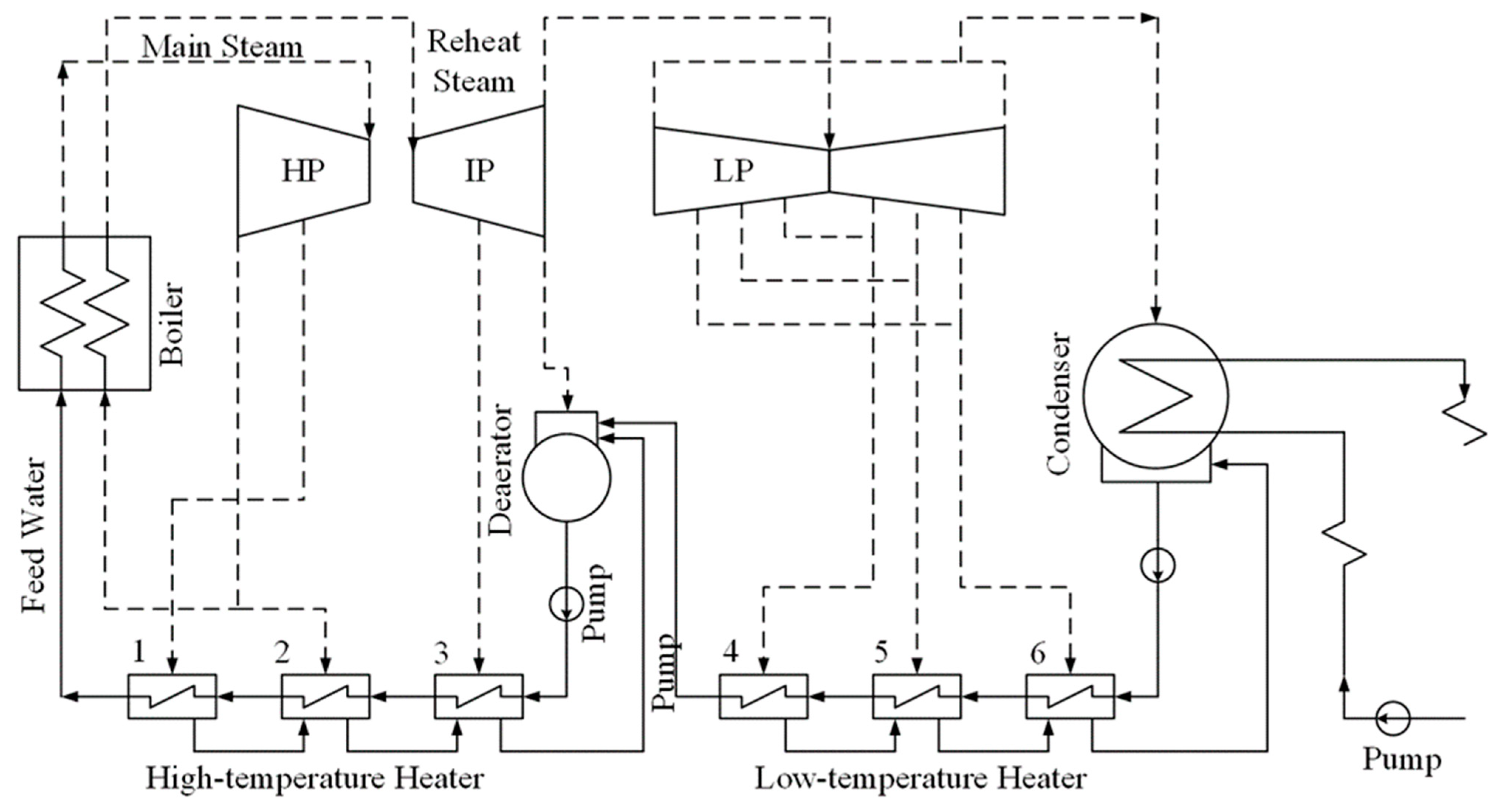
As shown in
Figure 8, the connected part of the thermal cycle and cooling system is the condenser. 1–6 represent the six heaters of power unit, steam and water flow are plotted with solid and dash lines. The different cooling system brings a different outlet temperature of circulating water under the same inlet temperature and mass flow rate. The heat transfer process in the condenser can be expressed as,
where
Qs equal to the mass flow rate of exhaust steam multiplies the enthalpy difference between steam and condensate water.
The heat transfer performance of the condenser can be calculated from the experimental data from HEI [
37],
where
K0,
Kw,
FM, and
FC are correction factors.
The steam temperature inside the condenser and the enthalpy difference for the steam side can be determined by the pressure and vice versa. Thus, with the heat transfer model of the individual system and Equation (25), the backpressure can be obtained with known ambient conditions of air and the mass flow rate of exhausted steam.
To evaluate the trade-off of water consumption and efficiency improvement of cooling systems, the coupled power unit operates at a constant load to convert the variations of efficiency improvement into variations in coal consumption. Thus, the nexus between energy and water can be evaluated together. An integrative method is adopted to solve the coal consumption rate under different backpressure.
Steam from the boiler is assumed firstly, the extraction pressures of each stage under different backpressure can be obtained with the help of improved Flugel formula [
38],
where
M and
P are the mass flow rate and pressure of steam of each stage group.
The enthalpy of extraction steam is calculated with the inlet enthalpy of the previous stage group,
where
H is the isentropic enthalpy variations and
η is the mean isentropic efficiencies, fitted based on operation data.
The mass flow rate of extraction steam and exhausted steam is calculated with its balance equation,
The output power of the new backpressure can be obtained with the assumed mass flow rate from the boiler,
The mechanical efficiency, ηm, and the effectiveness of the generator, ηg are regarded as constant. Compared with the rated power, adjust the mass flow rate input firstly until the relative error between the result of Equation (31) and the rated is acceptable, output the enthalpy and mass flow rate of exhaust steam as the input parameters of cooling system.
The operation cost of the boiler can also be solved,
3. Iterative Method with Model Validation
All the operation parameters and relationships have been analyzed in
Section 2. To evaluate the trade-off between the water/energy nexus, the variations of the heat transfer rate of the different cooling systems at given ambient conditions are converted to the coal consumption rate of the power generating unit with constant power output. The four cooling systems have the same mass flow rate of circulating water to maintain a constant power of pumps.
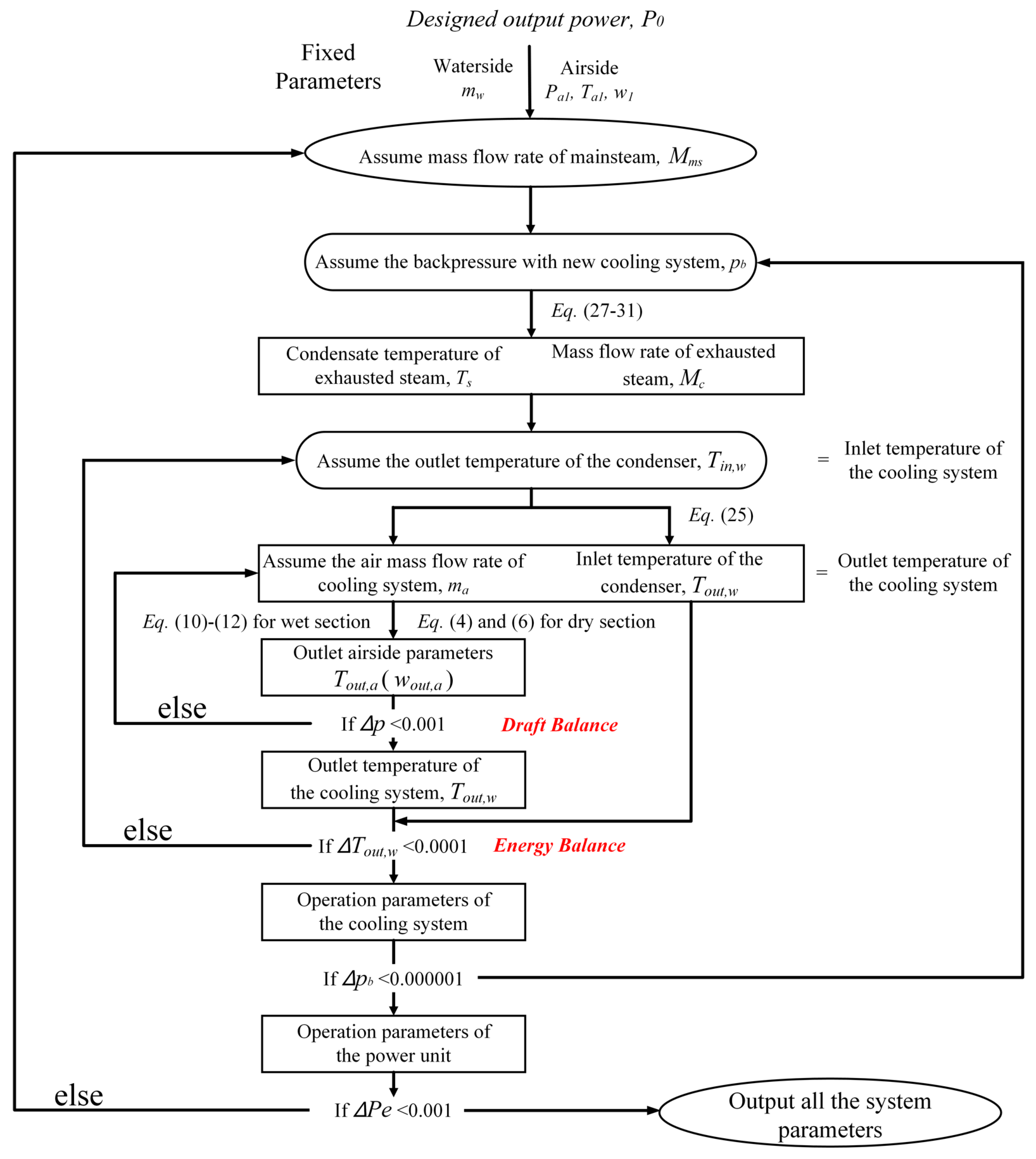
There are over 20 nonlinear equations to be solved, and it is hard to solve a complicated system simultaneously. With full consideration of the transfer parameters of each part, an iterative method is developed to analyze the performances. The detailed iteration steps are shown in
Figure 9.
- (1)
Calculate the boundary parameters of different cooling systems with approximate parameters of the thermal cycle. When assuming the mass flow rate of mainsteam and the backpressure, the operation parameters of the steam side are obtained, including the heat transfer rate in the condenser, which is equal to the heat transfer rate of cooling systems.
- (2)
Calculate the operation parameters of different cooling systems. Solve the equations of draft balance and energy balance of each cooling system with an initial water inlet temperature. Then the heat transfer rate of the cooling system can be obtained with a satisfying draft balance and energy balance. Check the consistency of this heat transfer rate with that corresponding to the backpressure in the first step. Otherwise, change the initial backpressure.
- (3)
Validate the output power of the unit. With the known mass flow rate of the mainsteam and the new backpressure, the output power of the unit can be calculated by Equations (27)–(31). Check the consistency of the output power and the design value, using a new mass flow rate of the mainsteam, and repeat step 1–2 to ensure all the equations are balanced.
The corresponding variables are summarized as follows,
A 660 MW supercritical coal-fired power generating unit coupled with NDDC has been simulated and validated with the operation data in our previous work [
39]. The geometric parameters of NDDC, as well as its heat transfer rate at design ambient conditions, are shown in
Table 1.
As for wet section, fills are selected from a typical NDWC, which have the same mass transfer and loss coefficient. Mathematical model for wet section in this study is verified from several NDWC systems in the literature [
36,
40]. The water outlet temperature of different wet cooling systems under specific ambient conditions shows relatively small differences, as shown in
Table 2.
5. Case Study with Discussion
5.1. Thermal Performance of Cooling Systems
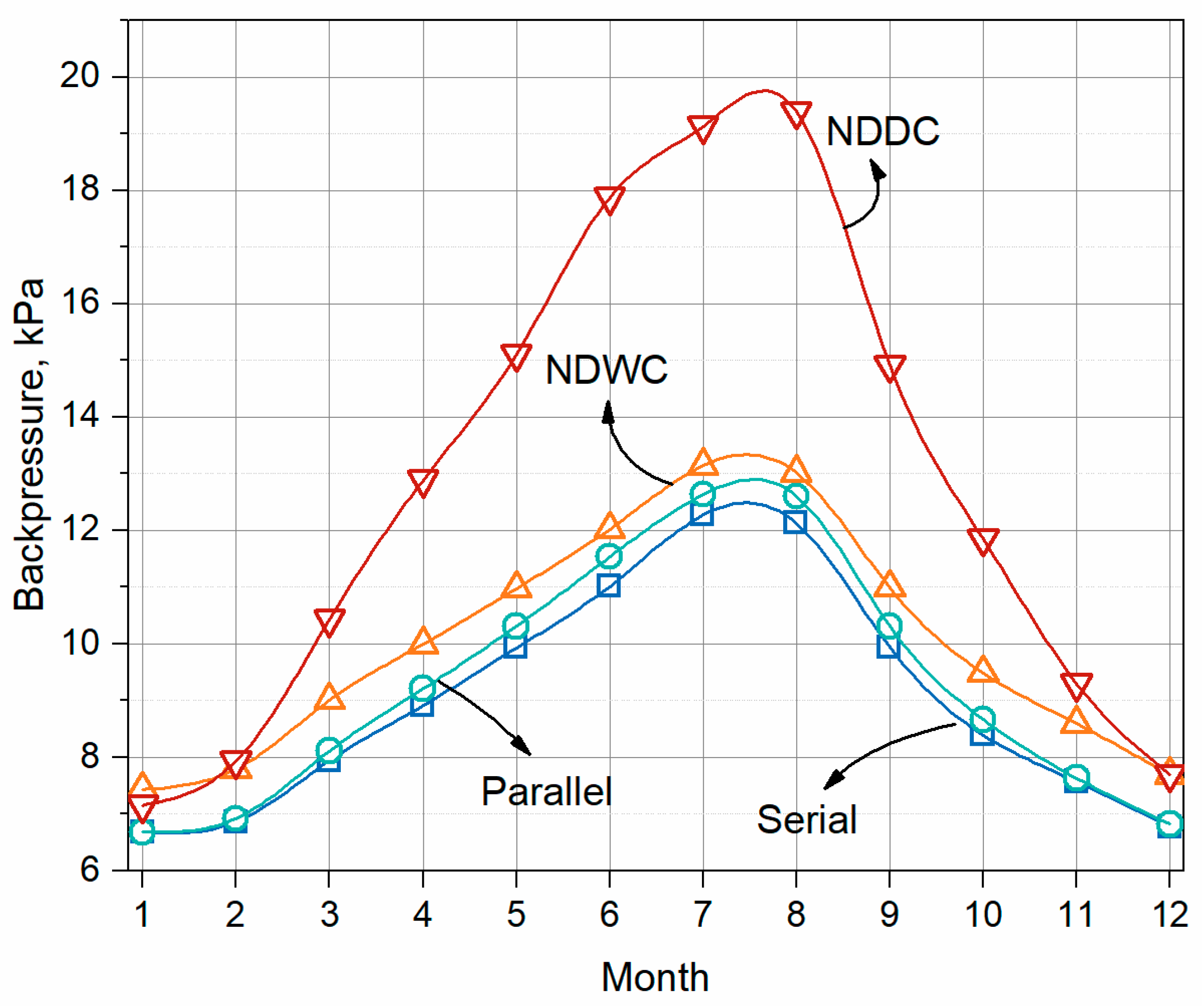
With mass flow rate and inlet temperature of circulating water of NDDC at design conditions, the thermal performance of each cooling system can be calculated. Performances of the cooling system during different months are shown in
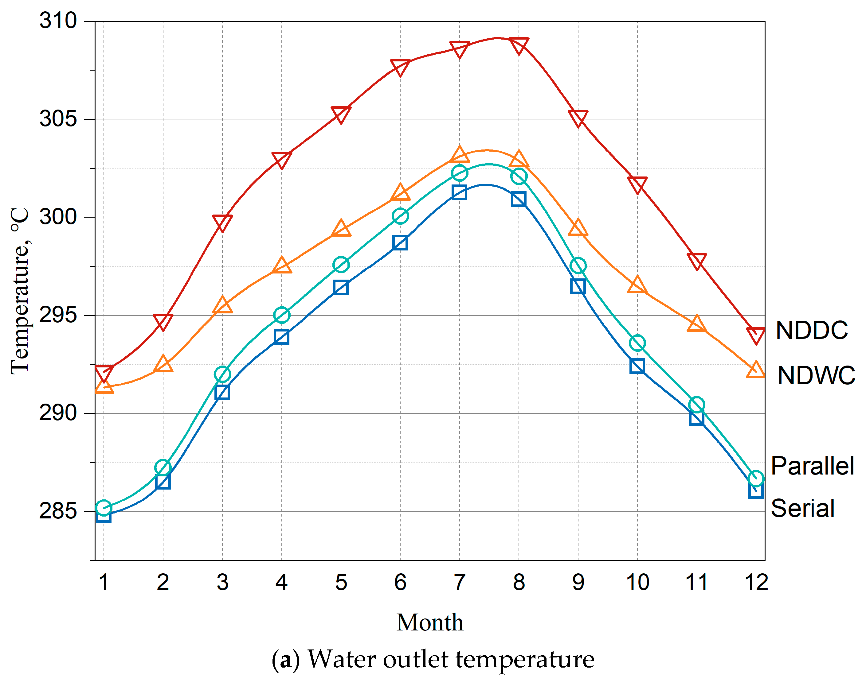
Figure 10.
The performance of a natural draft-type cooling system is significantly affected by ambient conditions. The waterside outlet temperature of different cooling systems from low to high is NDHC in serial heat exchange, NDHC in parallel heat exchange, NDWC, and NDDC.
Compared with other systems, the dry section has the lowest heat transfer efficiency since it transfers sensible heat. During the relatively cold weather, the difference between the dry section and wet section gets close. It is concluded that when the ambient temperature becomes lower, NDDC will achieve a higher heat transfer efficiency than NDWC in the current design.
The two kinds of hybrid cooling systems have a better performance than traditional cooling systems. The cooling efficiency of NDHC in the serial design is higher each month than that of the parallel design. With the rise in ambient temperature, the outlet water temperature difference varies from 2.23% in January to 0.6% in July, taking the serial design as an example.
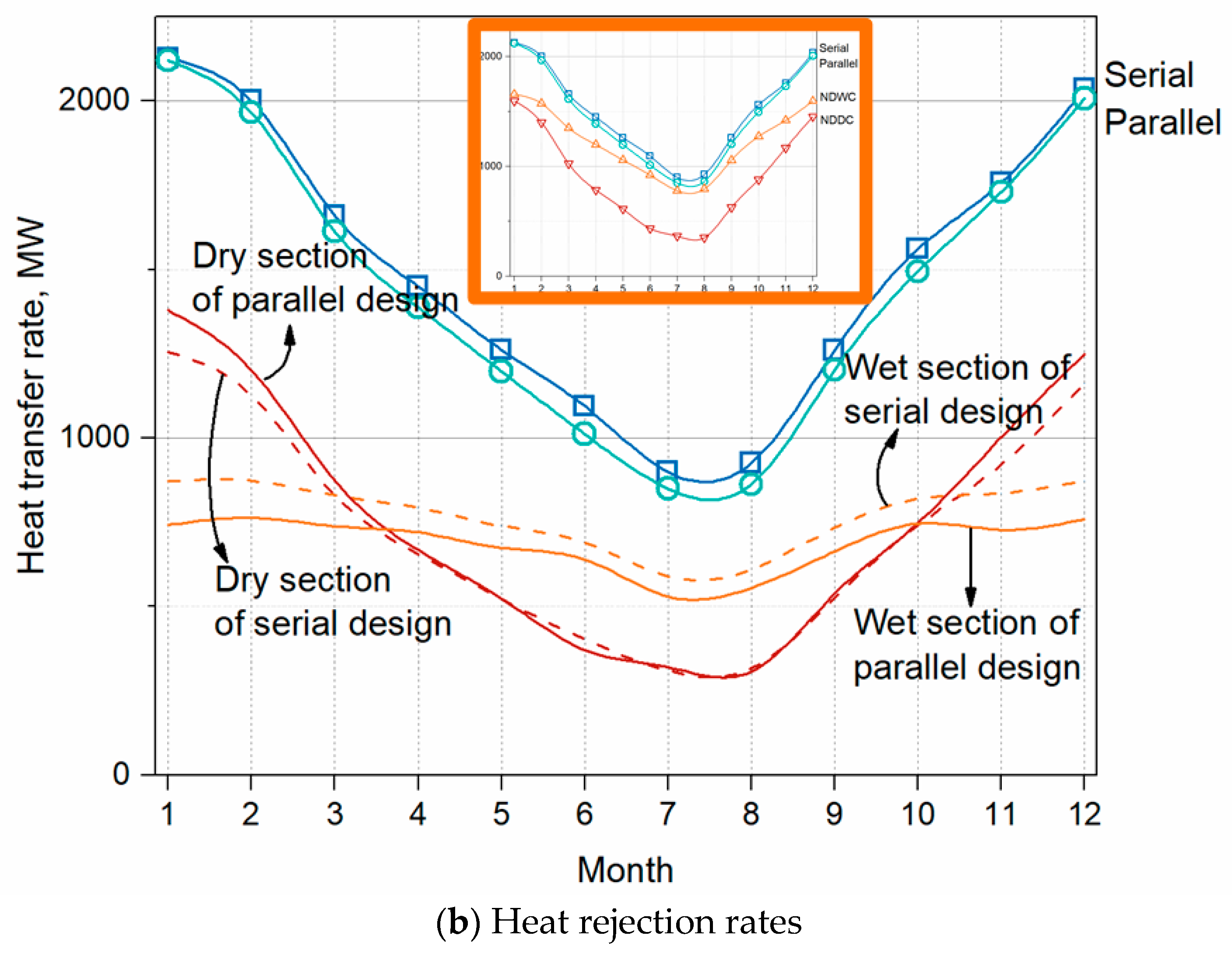
The monthly variations in the heat rejection rate of the two hybrid cooling systems are shown in
Figure 10b. From April to October, the heat transfer rates of the two dry sections are nearly identical, while the wet section of the serial design transfers more heat than the parallel design. Even if there is a reverse trend in the heat transfer rate of dry sections during cold weather, such as January, the difference between wet sections can still cover it.
To reveal the relationships between cooling efficiency and ambient conditions, the detailed parameters of both airside and waterside along its path are analyzed.
5.2. Influence of Ambient Conditions on Dry Cooling and Wet Cooling
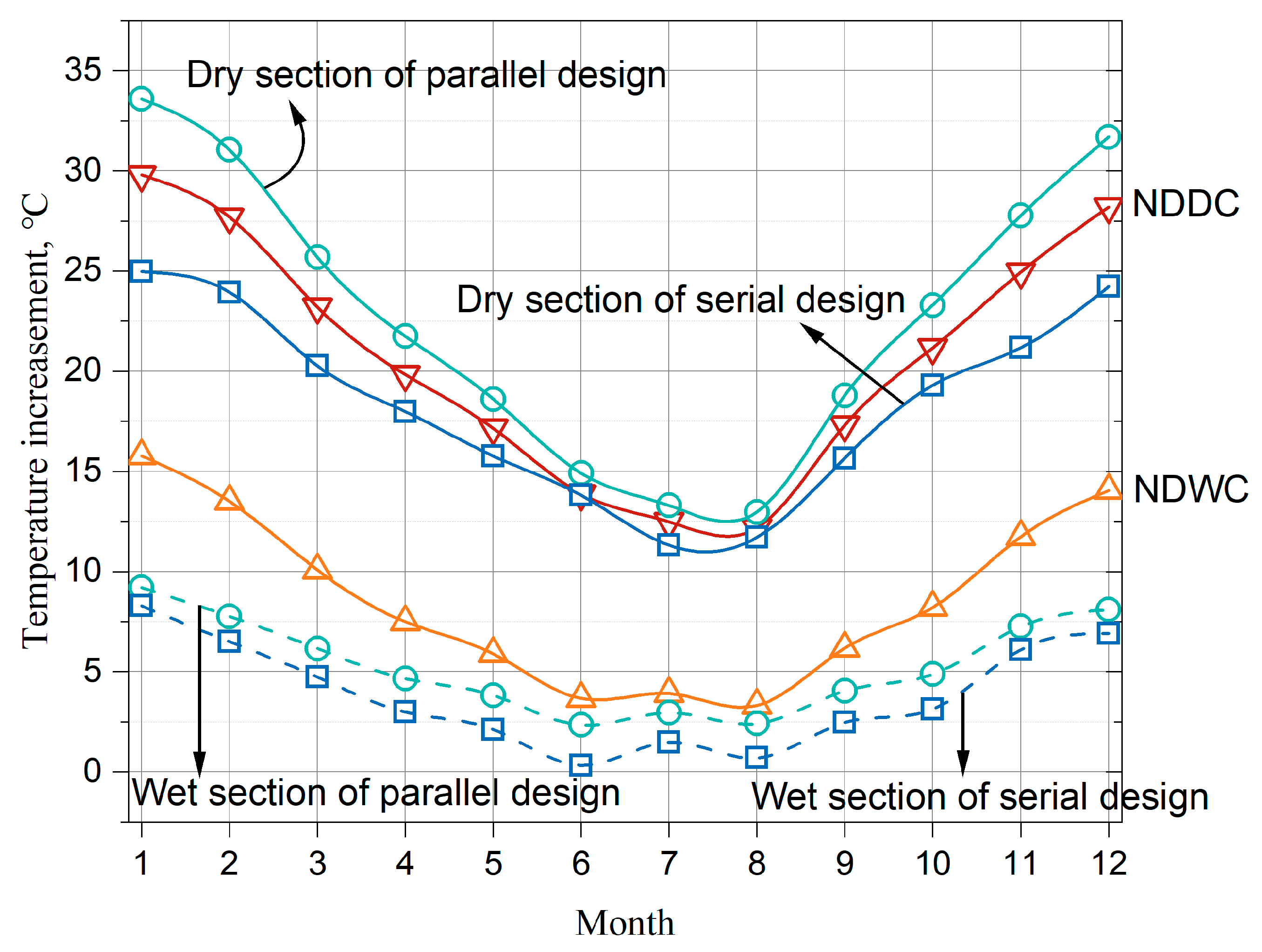
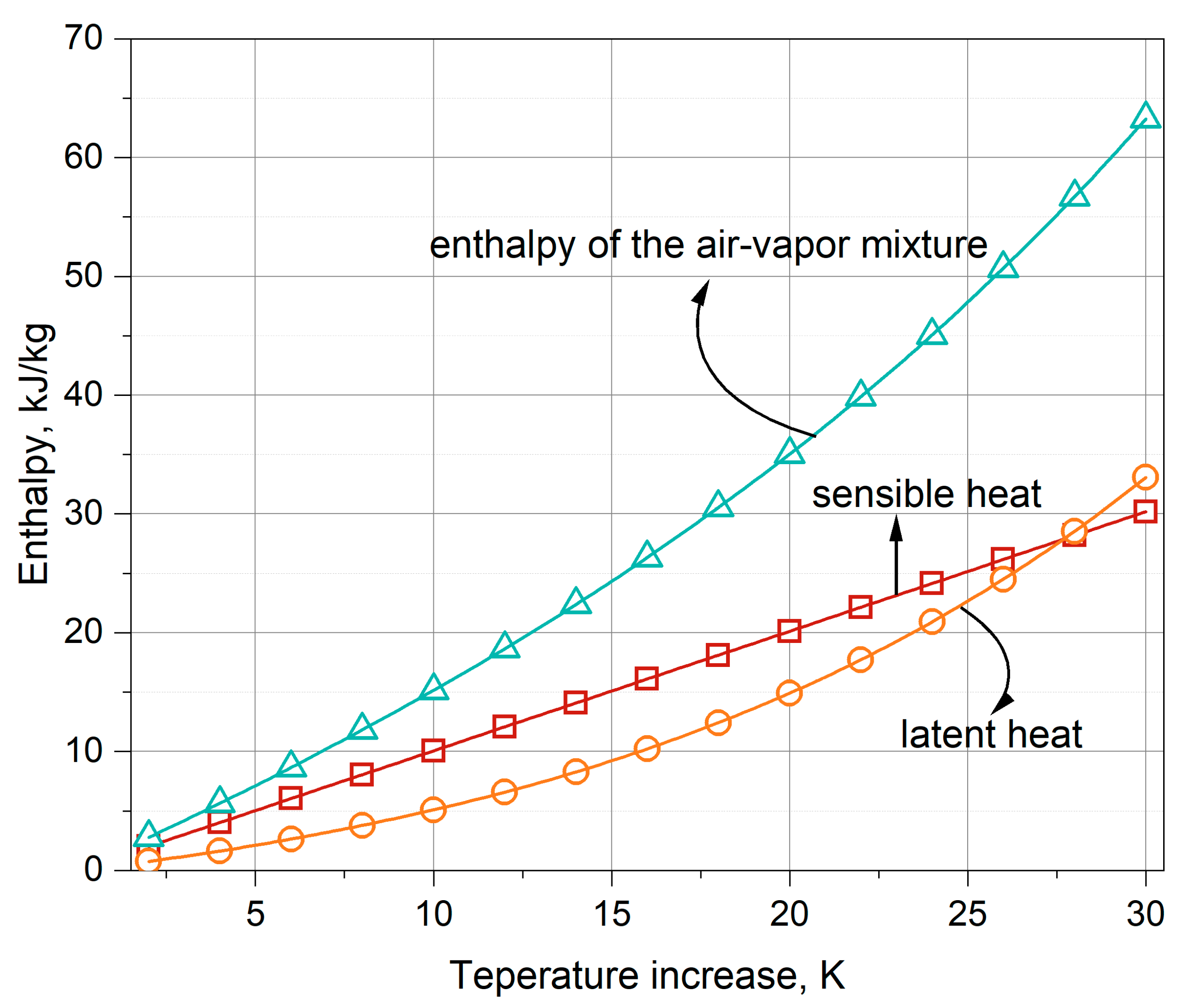
Enthalpy variations of the saturated air-vapor mixture with the increasement of air temperature with a basic temperature of 263.15 K are shown in
Figure 11. The green line and red line represent the air-vapor mixture and dry air, respectively. The cross point means at a relatively lower temperature, the sensible heat of pure dry cooling can cover the latent heat of pure wet cooling. The temperature increasements of the four cooling systems during different months are shown in
Figure 12.
In January, airside temperature increases by 29.8 K for NDDC and 15.8 K for NDWC, and the difference in enthalpy of NDDC and NDWC is about 4.4 kJ/kg. As for August, the differences between airside temperature increasement and enthalpy are 8.6 K and 23 kJ/kg. The higher airside temperature difference of NDDC brings more air passing through the tower, covering the relatively small enthalpy difference in cold weather. That is the reason that dry cooling has a better cooling efficiency in winter, with its performance going down rapidly in summer than wet cooling.
5.3. Influence of Ambient Conditions on Hybrid Cooling
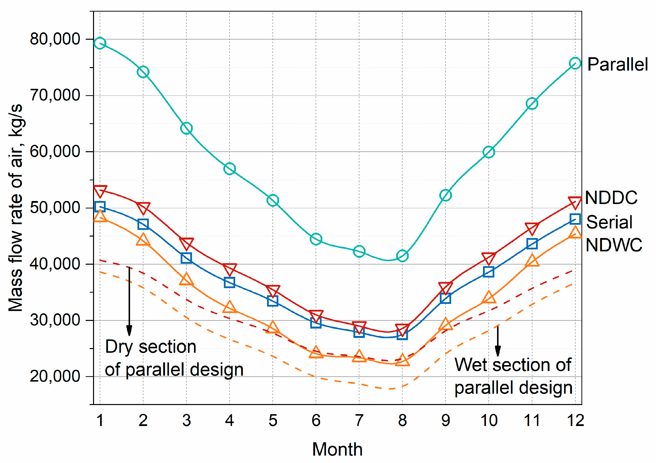
Though both of the two-hybrid cooling designs have better cooling efficiency than either dry cooling or wet cooling, there are different reasons behind it. The detailed airside mass flow rate is shown in
Figure 13.
From
Figure 10 and
Figure 13, it is concluded that the expanded inlet areas of hybrid cooling in the parallel heat exchange design bring high heat transfer performance. The air is warmed without moisture transfer and then the bulk temperature at the outlet of the dry section is higher than that of air from the wet section. The mixed process obtains a lower temperature, and the drive force of the dry section decreases. As for the wet section, water flowing into the wet section has been cooled by the air of ambient temperature from heat exchangers. For the same reason, the air mass flow rate of the wet section is much lower than NDWC. The difference between the airside mass flow rate of dry section and wet section of hybrid cooling in parallel heat exchange design and NDDC/NDWC will be more obvious during cold weather. The differences in the heat transfer rate of dry section and NDDC are 21.3% in January and 9.7% in August, respectively.
Things are different for hybrid cooling in the serial heat exchange design. Air flows through packing fills and heat exchangers successively, the loss coefficient for such a design is a sum of individual sections. The air mass flow rate of the wet section equals the dry section. As mentioned above, dry cooling contributes to a higher drive force than wet cooling. Airflow is pre-heated by the wet section and reaches a higher temperature after the dry section than NDDC. The effect of pre-heating will be better during winter. The airside mass flow rate of serial design is in the middle of NDDC and NDWC and approximates the NDDC in summer and NDWC in winter. The relative differences in airside mass flow rate of the serial design and NDDC are 5.6% in January and 3.8% in August, while 3.8% in January and 17.5% in August for NDWC. In a word, a higher temperature of the air at the outlet of the dry section maintains a larger airside mass flow rate, obtaining a high-efficient cooling system.
Compared with the two hybrid cooling systems, the serial design type relies more on the heat transfer performance of the wet section and the dry section for the parallel design. That means the heat transfer performance difference between the parallel design and NDWC will be larger when the ambient temperature goes up.
A sensitive analysis for the three cooling systems with wet sections is conducted under different ambient temperatures and humidity, as shown in
Table 7.
The water outlet temperature of NDHC in serial heat exchange mode keeps the lowest during the range above. As for NDWC and NDHC in the parallel heat exchange mode, when the ambient temperature reaches 34 °C, a higher cooling performance is achieved by pure wet cooling. The small temperature difference between inlet water and ambient air brings less air flowing through the tower, the relative difference in air mass flow rate of NDWC and the wet section reaches 23.36% at 34 °C, with humidity of 20%, compared to 15.6% at 26 °C, with humidity of 20%. It validates the analysis that the parallel design type relies more on the heat transfer performance of the dry section. Based on the data in
Table 6, a regression analysis is conducted,
The results indicate that NDHC in the serial design is more sensible to ambient humidity, while NDHC in parallel design is more sensible to ambient temperature. NDWC is at the middle of the two hybrid cooling modes. The conclusions keep consistency with the annual thermo-flow analysis above.
5.4. Water Consuming
NDDC is preferable due to its water-saving characteristic. Hybrid cooling constructed in this study shows priority over NDDC in view of heat transfer performance, the detailed water consumption rates of the three systems with wet cooling are analyzed in this subsection.
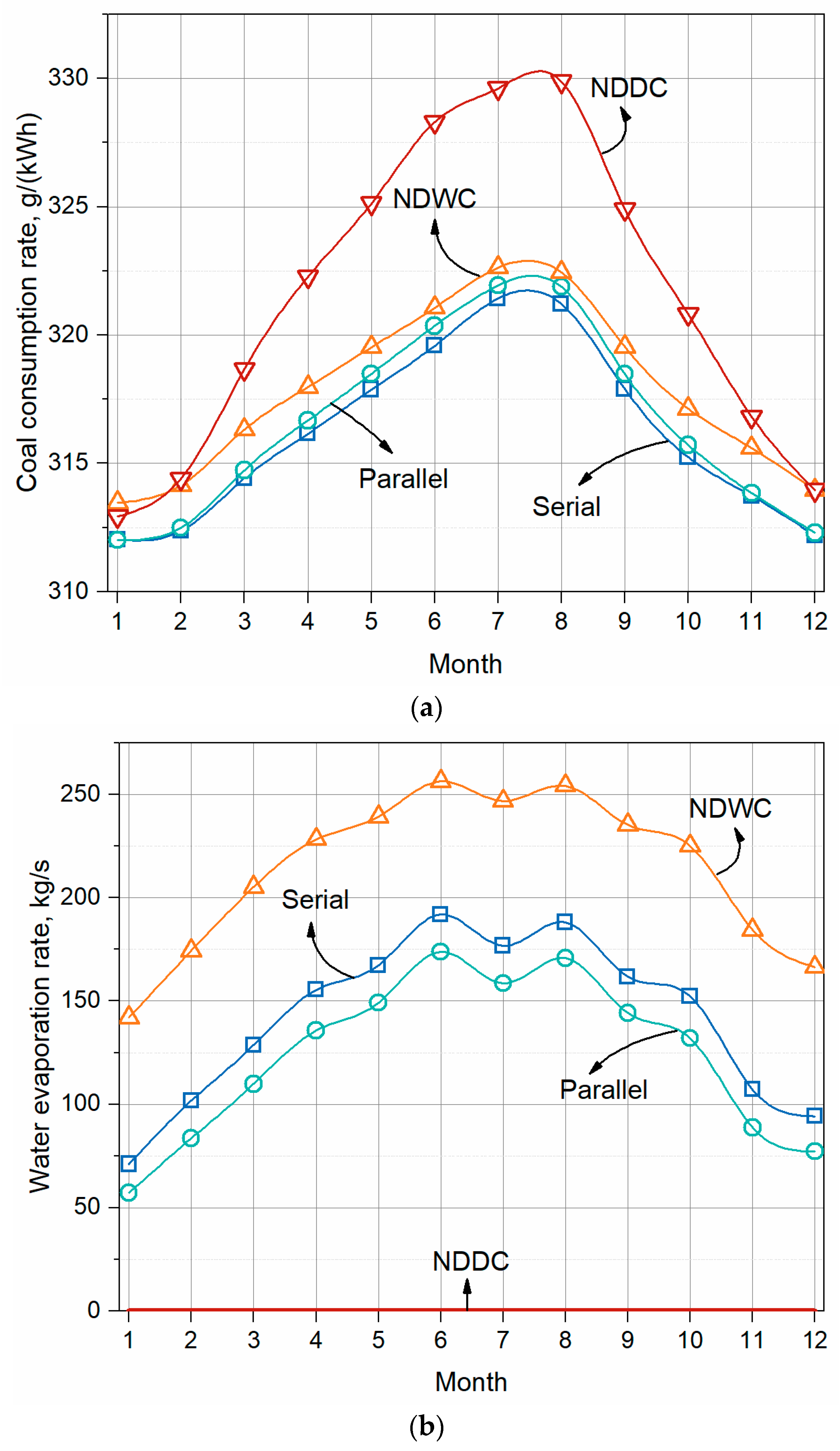
Two indexes can be adopted to give a comparative conclusion, water evaporation rate in (kg/s) and (kg/s)/MW. Water consumption in (kg/s) can be calculated with humidity variations of airside before and after packing fills,
The annual water consumption rates in (kg/s) for the four cooling systems are shown in
Figure 14.
As mentioned in
Section 5.3, water flowing into the wet section of the two hybrid cooling systems has a lower temperature than NDWC. Though the serial design has more airflow passing through the packing fills, it still consumes less water than NDWC. That larger difference in water consumption rate exists during cold weather since more heat is rejected in the dry section, as shown in
Figure 10. With the ambient temperature going up, though the mass flow rate of air in the wet section of the two hybrid cooling systems decreases, the warm air can absorb more moisture. The sharp decrease from June to July is because of the humidity variations, from 56.7% to 75.6%.
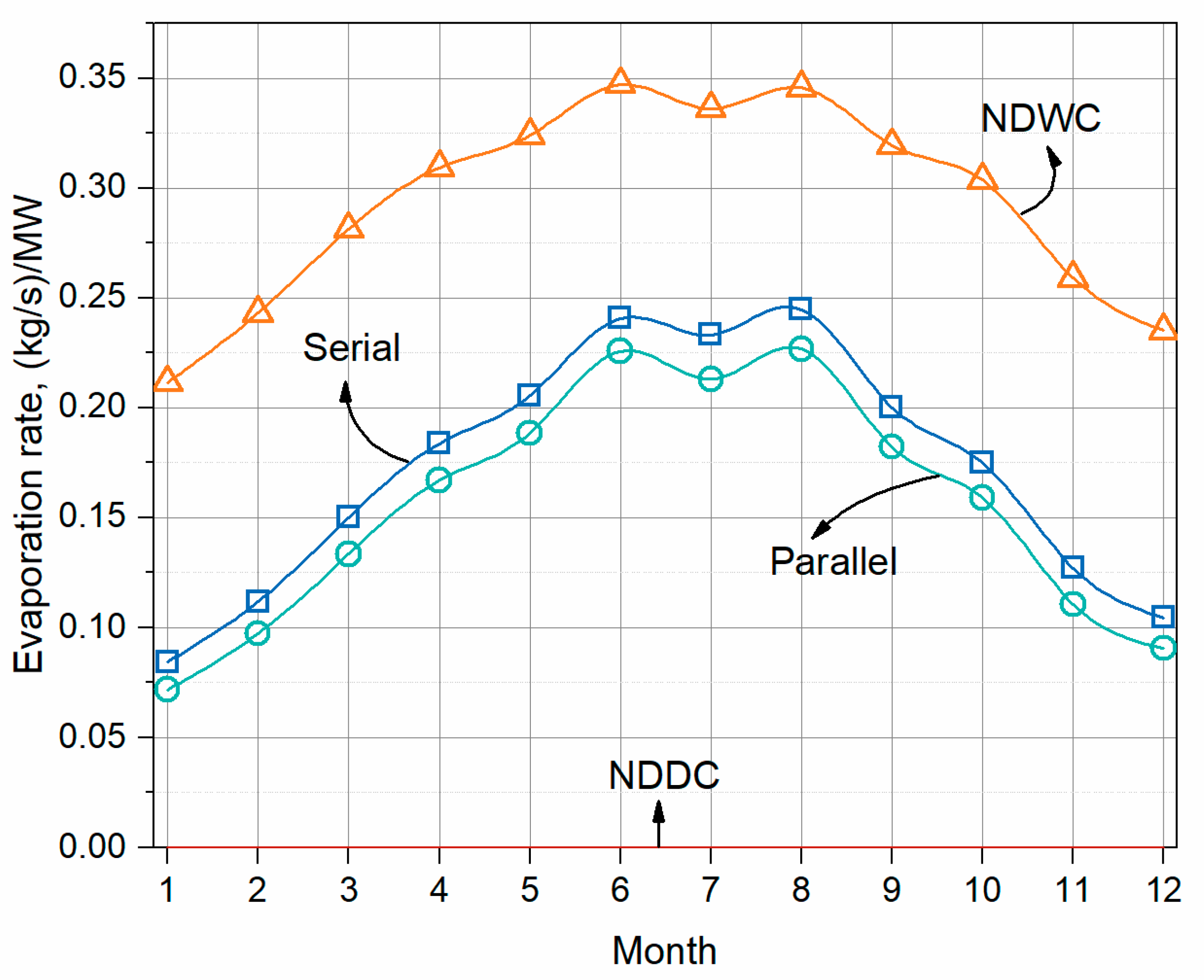
As the water evaporation rate in (kg/s)/MW is calculated as,
The annual water consumption rates in (kg/s)/MW for the four cooling systems are shown in
Figure 15.
A similar trend among the cooling systems is obtained. As long as there is a heat load in the dry section, hybrid cooling consumes less water per MW than NDWC. However, the amount of water remains a large consumption when compared with NDDC. More heat transfer rate for a cooling system under a constant inlet temperature means a relatively low inlet temperature of a condenser, and a lower inlet temperature of the cooling system as contrast is achieved. The evaporation rate will decrease somewhat. Considering the larger cooling efficiency provided by the hybrid cooling systems, the economic point may exist.
5.5. Economic Trade-Off
Based on the thermodynamic iteration steps in
Figure 9, annual backpressure variations of the power generating unit coupled with different cooling systems are calculated, shown in
Figure 16.
As mentioned in
Section 5.2, dry cooling shows more priority during cold weather. When coupling with a power generating unit, the inlet water temperature of the cooling system decreases as ambient temperature goes down. Opposite results are obtained during January and December between the performance of the power generating unit coupled with NDDC and NDWC. As the rise of the bulk temperature of the air, there is more circulating water evaporating and diffusing into the air. This high-efficient heat transfer process ensures the low backpressure of the power plant coupled with NDWC during summer.
As for the two-hybrid cooling design, performances for its corresponding thermal show similar trends with heat transfer rate. Hybrid cooling is proposed to achieve a water-energy balance in arid areas. The performances of cooling systems are expressed as the coal consumption rate of the whole unit with the help of Equation (32). The annual coal consumption rate as well as the water evaporation rate are shown in
Figure 17.
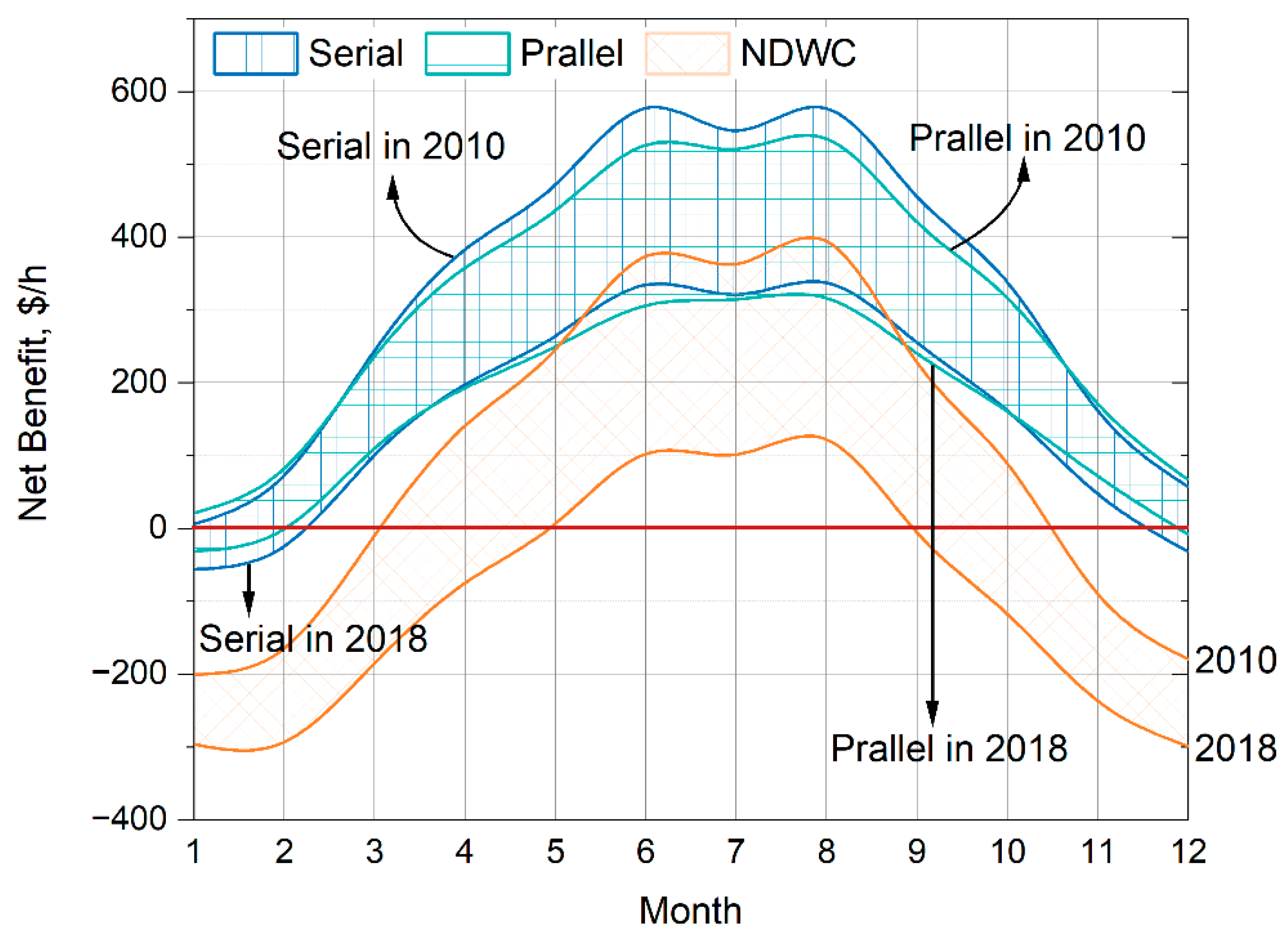
The trade-off of the consumption of water and energy can be calculated based on the actual price. Two typical years are chosen to represent different conditions. In 2010 with relatively inexpensive water resources, the unit cost of standard coal is 150 $/t and the unit cost of water treatment is 0.3 $/t. In 2018 with relatively cheap coal due to a large amount of renewable energy, the unit cost of the standard coal and water treatments are 130 $/t and 0.5 $/t.
The original cooling system, NDDC, is chosen as the reference with 0 benefits. The drop in coal cost and rise in water cost bring a sharp decrease in net benefit of the other three cooling systems. Especially for pure wet cooling, compared with two hybrid cooling systems, the difference reaches a maximum during the coldest weather. Hybrid cooling in parallel has less benefit loss during cold weather than the serial design. The results shown in
Figure 18 are only calculated at a point, besides the ranges caused by the market, operation hours will greatly affect the economy of cooling system selection.
There are too many factors affecting the actual operating hours of a coal-fired power plant, such as the capacity of renewable energy, heat and electricity demands, and the energy policy of the local government. These variables bring great uncertainty to predicting the operation hours, so the actual operation data of the power plant in this study are adapted to provide an analysis of applicability for the two market factors.
Recently, due to COVID-19 and heat supply demands in late 2020, there is a sharp rise in the unit cost of standard coal. How to cope with the variations in a market like that to design a suitable cooling system is the main concern in this study.
The actual operating conditions of the power plant are shown in
Table 8.
Considering the historical data, the unit cost of water treatment ranges from 0.2
$/t to 1
$/t, while the unit cost of standard coal from 100
$/t to 200
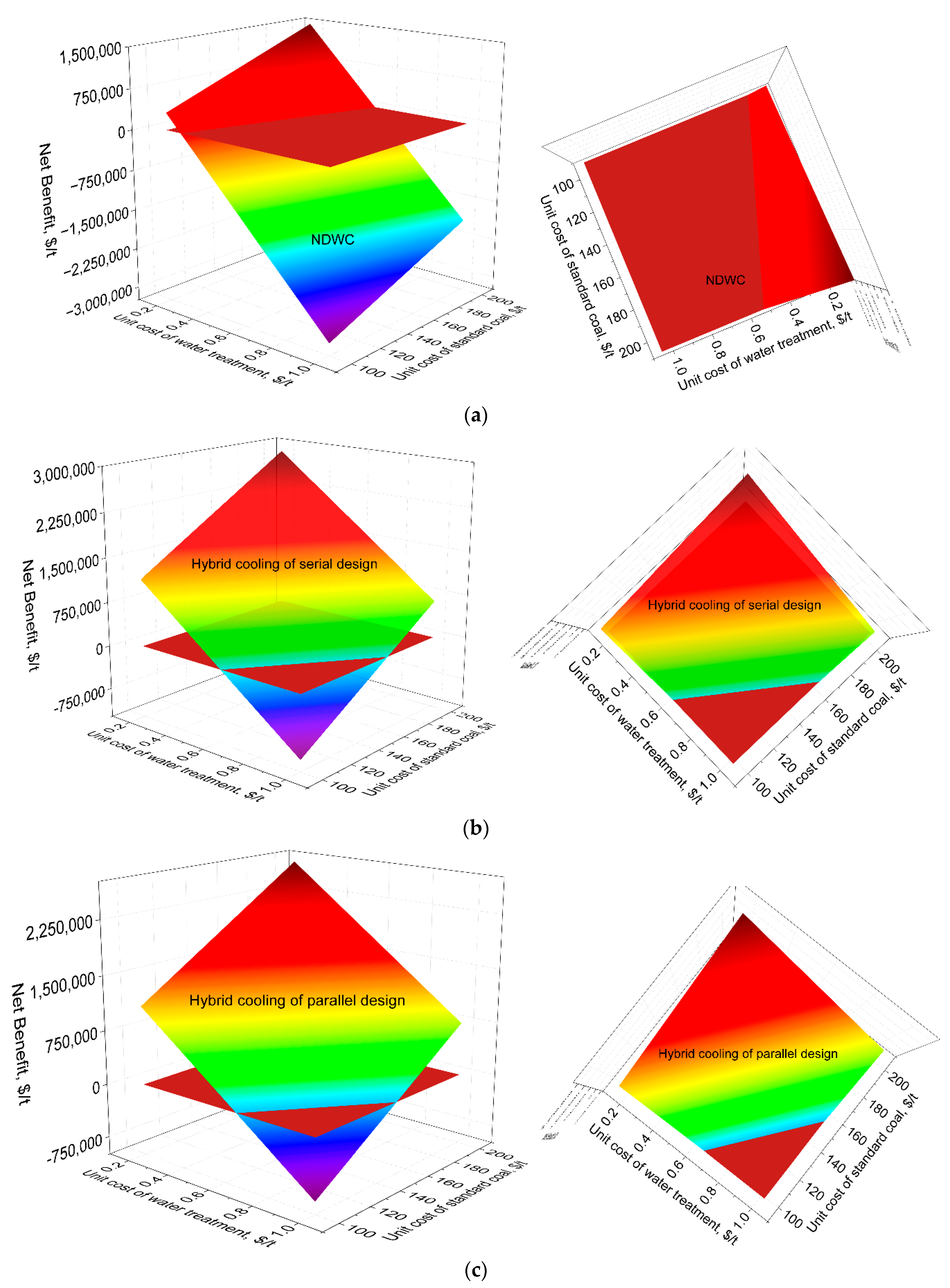
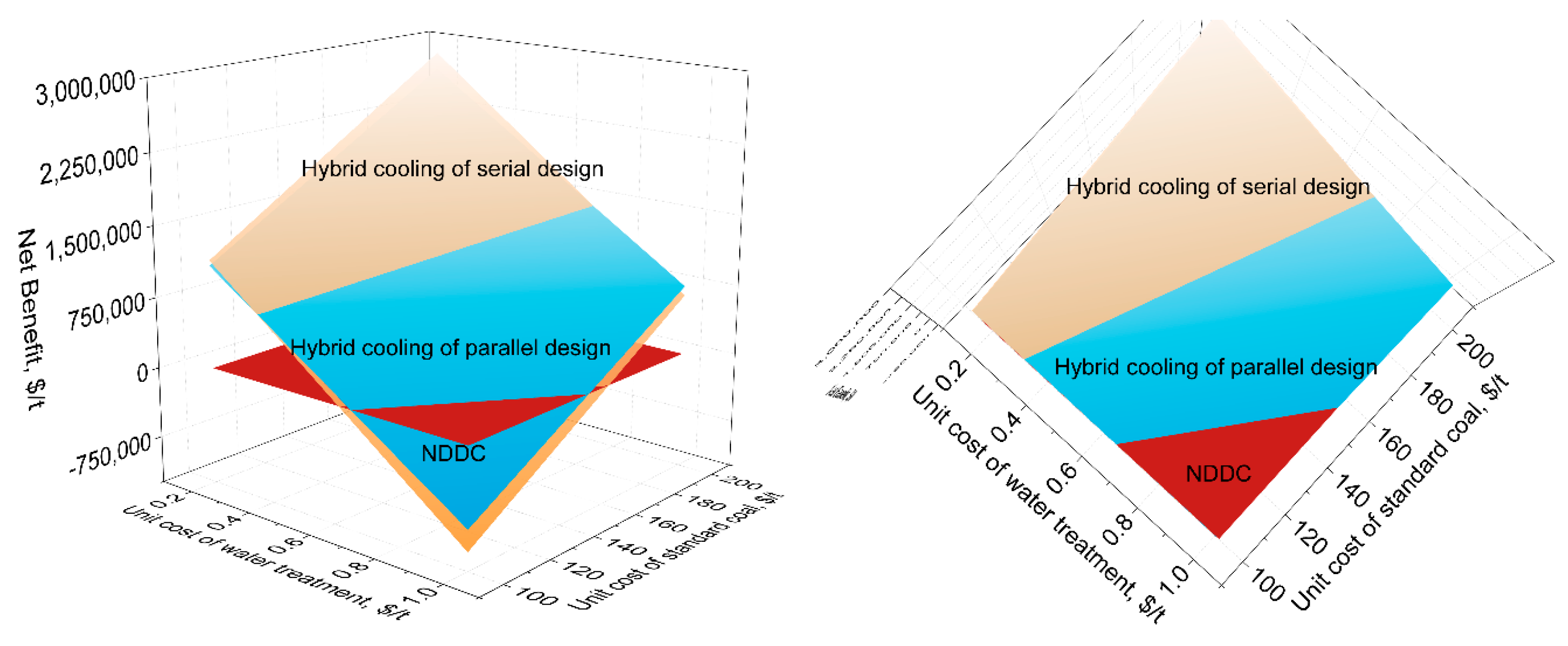
$/t is taken into account. The net benefits of the four cooling systems are calculated with the above data and plotted in 3D, as shown in
Figure 19.
The red plate represents NDDC, benefits of the other three cooling systems are colored with rainbow. The vertical axis in the 3D figure is the relative difference of benefit, which means the surface beyond the cross lines along with the positive direction of z represents the cooling system in this region and shows more priority to NDDC.
Figure 19 provides a roadmap for cooling system selection for different conditions of the market.
As shown in
Figure 19a, when the unit cost of water treatment is beyond 0.6
$/t, there will be no benefit for the power plant. The relatively low cost of coal, is the reason why dry cooling can be seen more in North China. The surfaces that represent positive benefits are much larger for the two hybrid cooling systems, detailed comparisons with the individual colored surface are shown in
Figure 20.
Compared with
Figure 19b,c, hybrid in parallel design has larger economic regions than the serial design. However, if there exist lower water costs or expensive coal resources, the serial type is preferable. The values of unit cost in the figure are suitable for the operation data in this study and for reference only. If the power plant mainly operates in summer for peak electricity demands or in winter for peak heat supply, conclusions will be completely opposite.


