Article

A Proposed Three-Phase Induction Motor Drive System Suitable for Golf Cars

by
Mohamed S. Elrefaey
1,
Mohamed E. Ibrahim
1,2,*,
Elsayed Tag Eldin
3,*,
Hossam Youssef Hegazy
4,
Samia Abdalfatah
4 and
Elwy E. EL-Kholy
2
1
Faculty of Technological Industry and Energy, Delta Technological University (DTU), Quwaysna 32631, Egypt
2
Faculty of Engineering, Menoufia University, Shebin El-Kom 32511, Egypt
3
Faculty of Engineering and Technology, Future University in Egypt, Cairo 11835, Egypt
4
Faculty of Industrial Education, Helwan University, Cairo 11835, Egypt
*
Authors to whom correspondence should be addressed.
Energies 2022, 15(17), 6469; https://doi.org/10.3390/en15176469
Submission received: 21 July 2022 / Revised: 31 August 2022 / Accepted: 1 September 2022 / Published: 5 September 2022

Abstract

:
In this paper, a proposed electric drive system for a three-phase induction motor is presented. The proposed drive system is suggested for a golf car as one type of electric vehicle. The suggested system consists of three similar single-phase buck–boost converters. Hence, each single-phase buck–boost converter is used as a buck–boost inverter and is used to energize only one phase of the induction motor. The suggested system has the advantage of high reliability, as it can deal with different fault conditions such as battery and motor winding faults. The suggested electric drive system depends on a buck–boost converter which gives variable voltages as well as variable frequencies. Thus, variable speeds of the electric vehicles can be easily achieved. A variable DC voltage (positive or negative) can be achieved at the output of the adopted buck–boost converter, which is considered another advantage of the proposed drive system. This DC voltage can be used to achieve braking of the induction motor used to drive the electric vehicle. Therefore, this advantage can be used instead of ordinary mechanical braking to increase vehicle reliability. To demonstrate our proposed idea, a simulation study is presented. The simulation is carried out using Power Simulation Program (PSIM) software. The simulation study takes into consideration the performance of the adopted buck–boost converter under different conditions to present its advantages. Furthermore, a performance study of the suggested induction motor drive system is carried out under different conditions ranging from healthy to faulty conditions to test system reliability. For more illustration, an experimental prototype of the adopted buck–boost converter is built, and its performance is studied. From all the obtained results, the efficacy of the proposed system is demonstrated.

1. Introduction

Recently, interest in using electric vehicles has increased. This increase comes due to global interest in reducing harmful emissions from traditional vehicles [1,2,3,4,5,6,7,8]. Therefore, there is great interest from researchers and manufacturers in increasing the spread of electric vehicles all over the world. Furthermore, advances in power electronics and control systems help in this increase. Hence, electric vehicles depend on using batteries to deliver the electric power to the driving electric motor. These batteries are charged from utility, PV panels, or both. The charging process is carried out via AC–DC converter when charged from utility or via DC–DC converter if charged from PV panels. However, electric power is delivered to the driving motor through a boost DC–DC converter feeding AC or brushless DC driving motors through DC–AC converters. Thus, there is great interest from researchers and scientists in improving the performance of the electric drive system of electric vehicles. For example, in studies [9,10,11,12,13,14,15,16,17,18], work to improve the design of boost DC–DC converters of the electric vehicle drive system as well as the charging system was carried out to improve their performances. Furthermore, in [19], a sliding mode observer to control an induction motor used to drive electric vehicles is suggested.
Golf cars are examples of electric vehicles which are extensively used in gardens, clubs, universities, etc. Modern golf cars use PV panels to charge their batteries in addition to their charging from utility, as shown in Figure 1. These types of cars use AC–DC converters to charge their batteries from utility. They also use DC–DC converters to charge the same batteries from PV panels. The driving AC motor is energized from these batteries via DC–AC converter through a boost-type DC–DC converter, as shown schematically in Figure 2. Furthermore, most types of golf cars use the tradition mechanical braking system. Generally, the main disadvantages of this drive system can be summarized in the following points:
  • When one phase of the motor is lost due to an open circuit or other causes, the motor does not have the capability to start when the car starts from rest. This comes as the generated electric field under this condition is not a rotating field. Therefore, the generated torque is equal to zero and the car needs to be carried to perform the required maintenance. This problem reduces the car’s reliability; therefore, this issue needs to be solved.
  • The adopted braking system of the conventional golf car depends on a mechanical braking system that suffers from the high need for maintenance. This represents another cause for reliability reduction. Therefore, a solution to this problem should be presented.
  • In the conventional golf car, if a failure occurs in some batteries at the same time, the driving motor gives a reduced torque and the car may not be able to be driven at the desired speeds. Therefore, there is a need for an improved drive system to overcome this problem.
Therefore, this paper presents an improved electric drive system for a three-phase induction motor to be used with golf cars, as one type of electric vehicle, to overcome the aforementioned issues. The suggested system consists of three similar single-phase buck–boost converters at which each converter is used to energize only one phase of the driving motor. The suggested system is designed to deal with different fault conditions such as battery and motor winding faults to increase car reliability. The suggested electric drive system depends on a buck–boost converter to give variable sinusoidal voltages and variable frequencies. Therefore, variable speeds of the electric vehicles can be easily achieved. The ability to obtain a variable magnitude DC voltage (positive or negative) at the output terminals of the adopted buck–boost converter is another advantage of the proposed drive system. This DC voltage can be used to achieve braking of the induction motor used to drive the vehicle. Therefore, this advantage can be used instead of mechanical braking in conventional golf cars to increase vehicle reliability. To illustrate the efficacy of the proposed system, a simulation study is carried out. The simulation is performed using Power Simulation Program (PSIM) software. The simulation study takes into consideration the performance of the adopted buck–boost converter under different conditions to present its advantages. Furthermore, the performance of the suggested induction motor drive system is observed in different cases ranging from healthy to faulty conditions to test system reliability. For more illustration, an experimental prototype of the adopted buck–boost converter is built and its performance is studied. From all the obtained results, the efficacy of the proposed drive system is demonstrated.

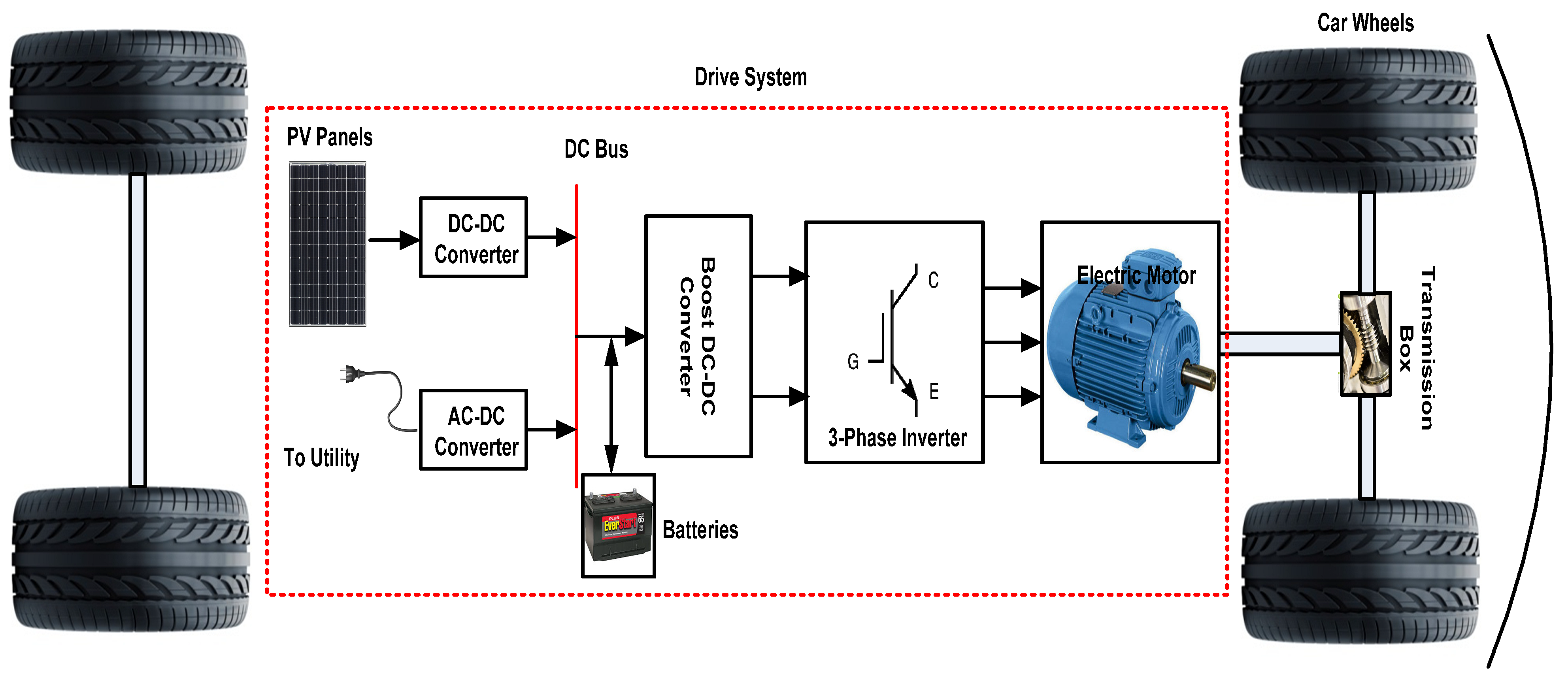
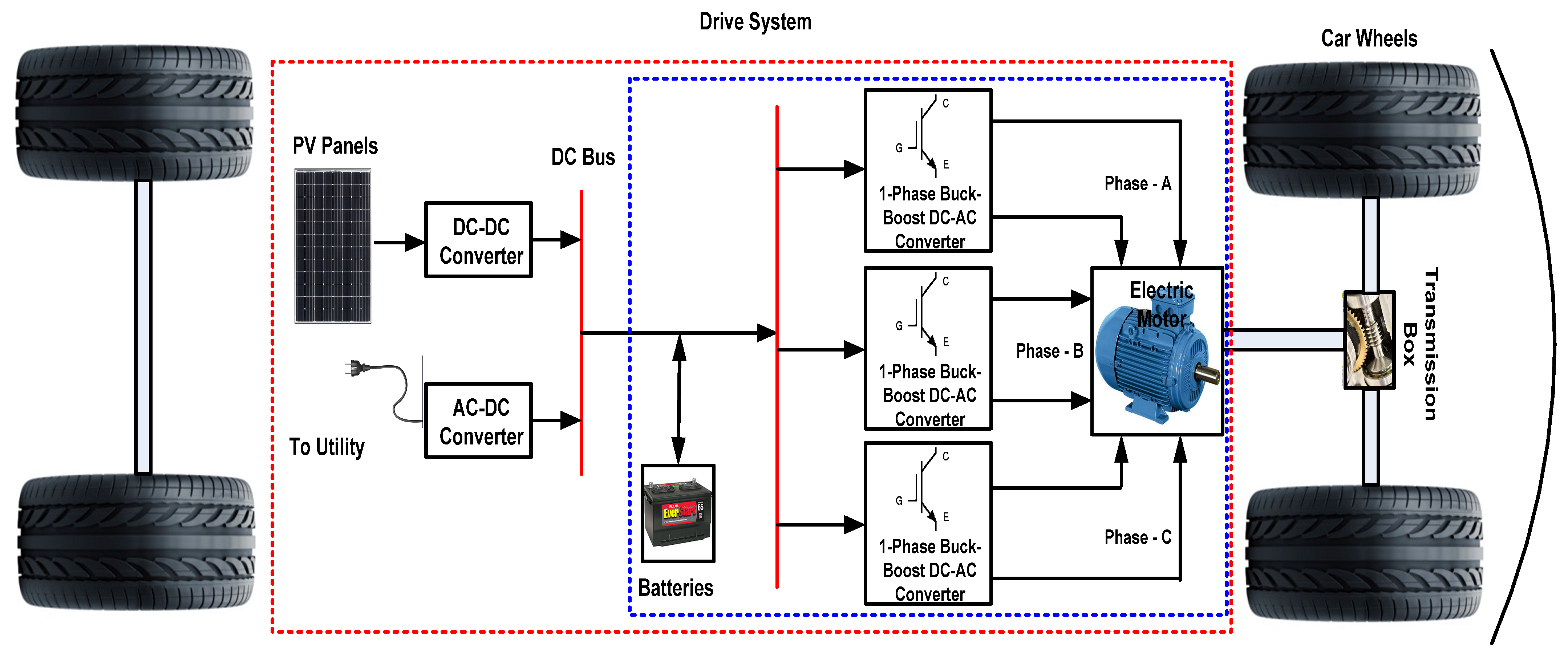
2. The Proposed Golf Car Drive System

Figure 3 shows the proposed electric drive system suggested for golf cars. The main differences between the proposed and conventional systems can be summarized in the following points:
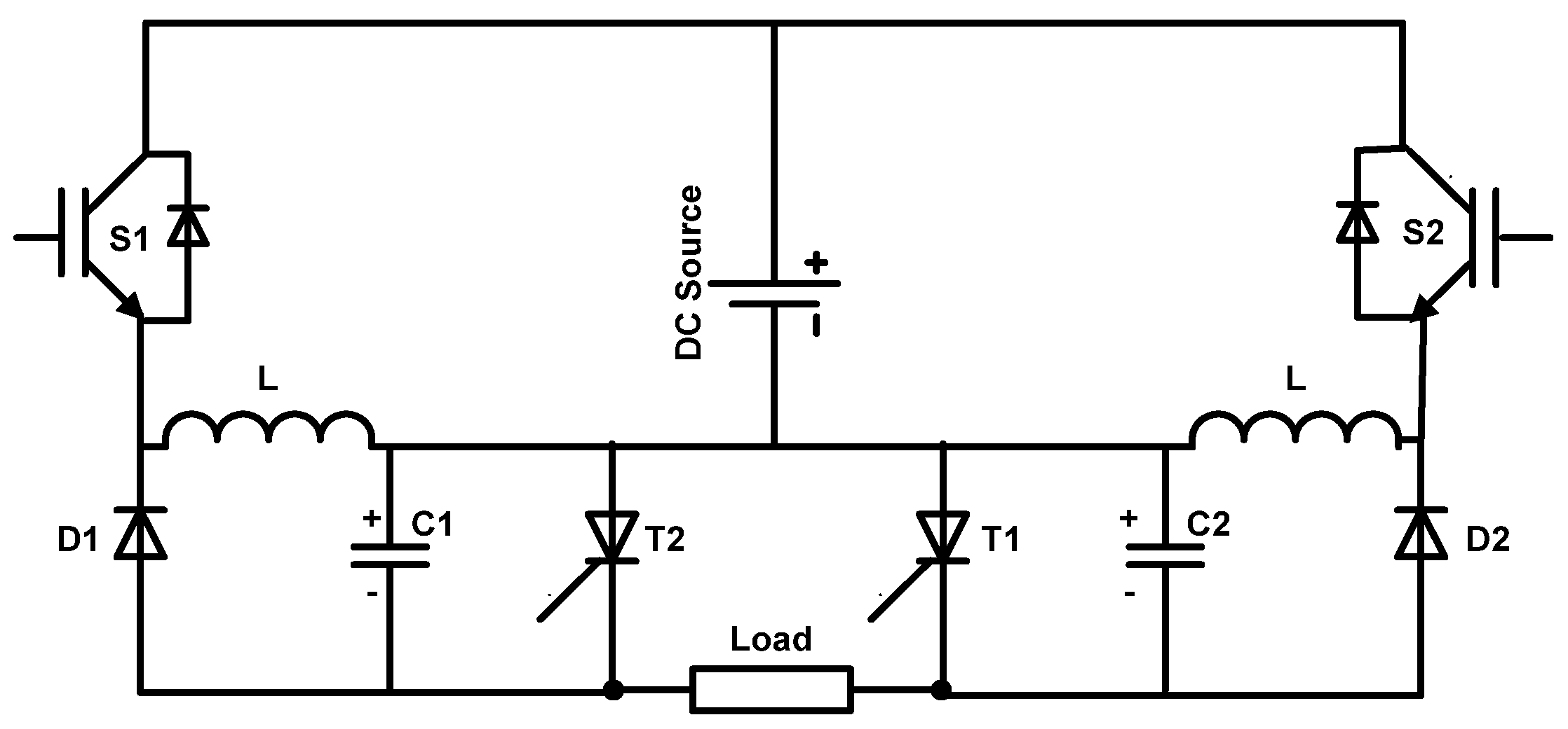
  • The boost DC–DC converter which feeds the three-phase inverter, as well as the three-phase inverter itself in the conventional drive system, are replaced with a single-stage buck–boost DC–AC converter.
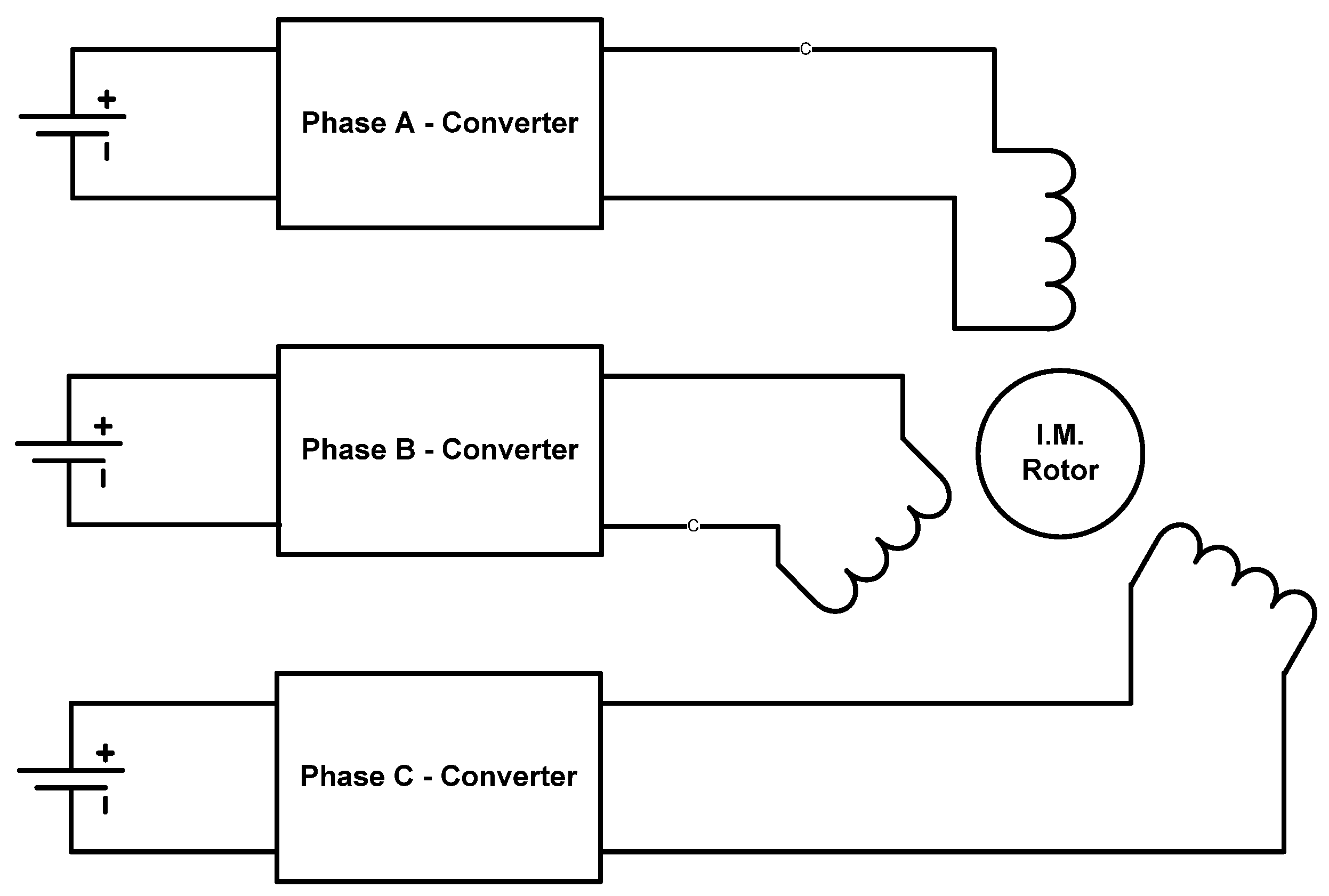
  • Three single-phase DC–AC buck–boost converters are used. Each converter is used to feed only one phase from the phases of the three-phase induction motor used to drive the car. Therefore, the six terminals of the three-phase induction motor are needed in the connection, as shown schematically in Figure 4.
  • The used storage batteries are divided to three groups with equal numbers of batteries. The first group is connected at the input of the DC–AC converter, and its output is connected to phase-A of the induction motor. However, the other two groups are connected to the inputs of the converters of the other phases; see Figure 4.
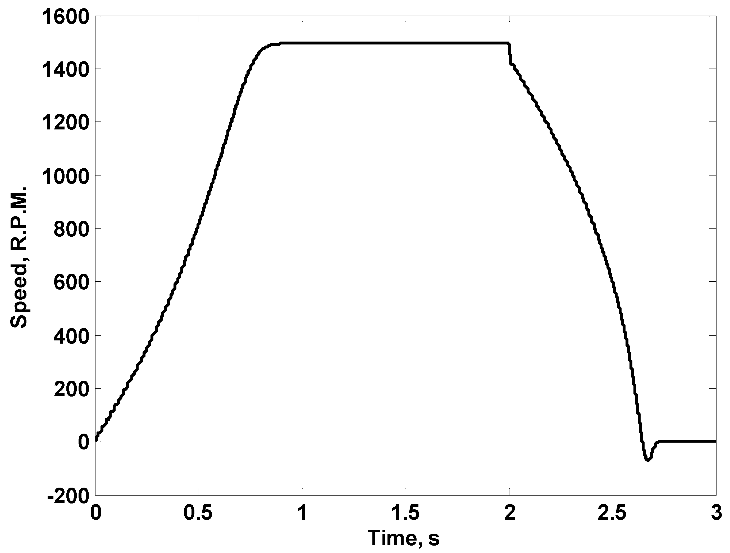
  • The main advantage of the adopted DC–AC buck–boost converter comes as its output can be controlled to be either +ve or −ve DC. Therefore, it is suggested to use this feature to provide braking to the car driving motor instead of the conventional mechanical braking.
To communicate the advantages of the adopted buck–boost DC–AC converter, its circuit diagram is shown schematically in Figure 5. Looking at this circuit, the converter consists of four switches. Two of them are Insulated Gate Bipolar Transistors (IGBTs) (denoted by S1 and S2) and the other two switches are thyristors (T1 and T2). Theory of operation of the adopted converter is deeply discussed by members of our research team in [20]. However, for more clarification, a brief description will be presented here with a stress on its feature to give +ve or −ve DC voltage at its output, as this feature is presented for the first time. In fact, the devices S1 and T1 are controlled to obtain the positive half-cycle of the output AC voltage. The pulses to S1 are generated from a closed-loop control system to control the left-hand side capacitor (C1) voltage to be a positively half-wave rectified sinusoidal waveform. The pulses to S2 are generated from the same closed-loop control system to control the right-hand side capacitor (C2) voltage to be a positively half-wave rectified sinusoidal waveform shifted by 180° compared to the voltage waveform of C1. The thyristor T1 is closed during the first half-cycle, so the voltage of C1 appears on the load with the same polarity. The thyristor T2 is closed during the second half-cycle, so the voltage of C2 appears on the load with reversed polarity. Therefore, the voltage appearing on the load terminals is expected to be a nearly sinusoidal waveform. For more clarification, the reader can see Figure 6, which displays the adopted control technique and the illustration of circuit operation.
To obtain a +ve DC voltage at the output terminals of the converter, the control technique illustrated in Figure 7 can be adopted. This control technique uses its reference as DC voltage. The generated pulses under this condition control S1 to achieve DC voltage with values lower or higher than the input DC voltage (depending on the duty ratio) at the terminals of C1. However, T1 is closed to discharge C1 in the load in the +ve direction. Similarly, −ve DC output voltage can be obtained using the same control technique to control the switches S2 and T2. This generated DC voltage can be used to provide a braking of the three-phase induction motor used to drive the car.

3. Simulation Study and Results

In this study, four different cases are presented. These cases are:
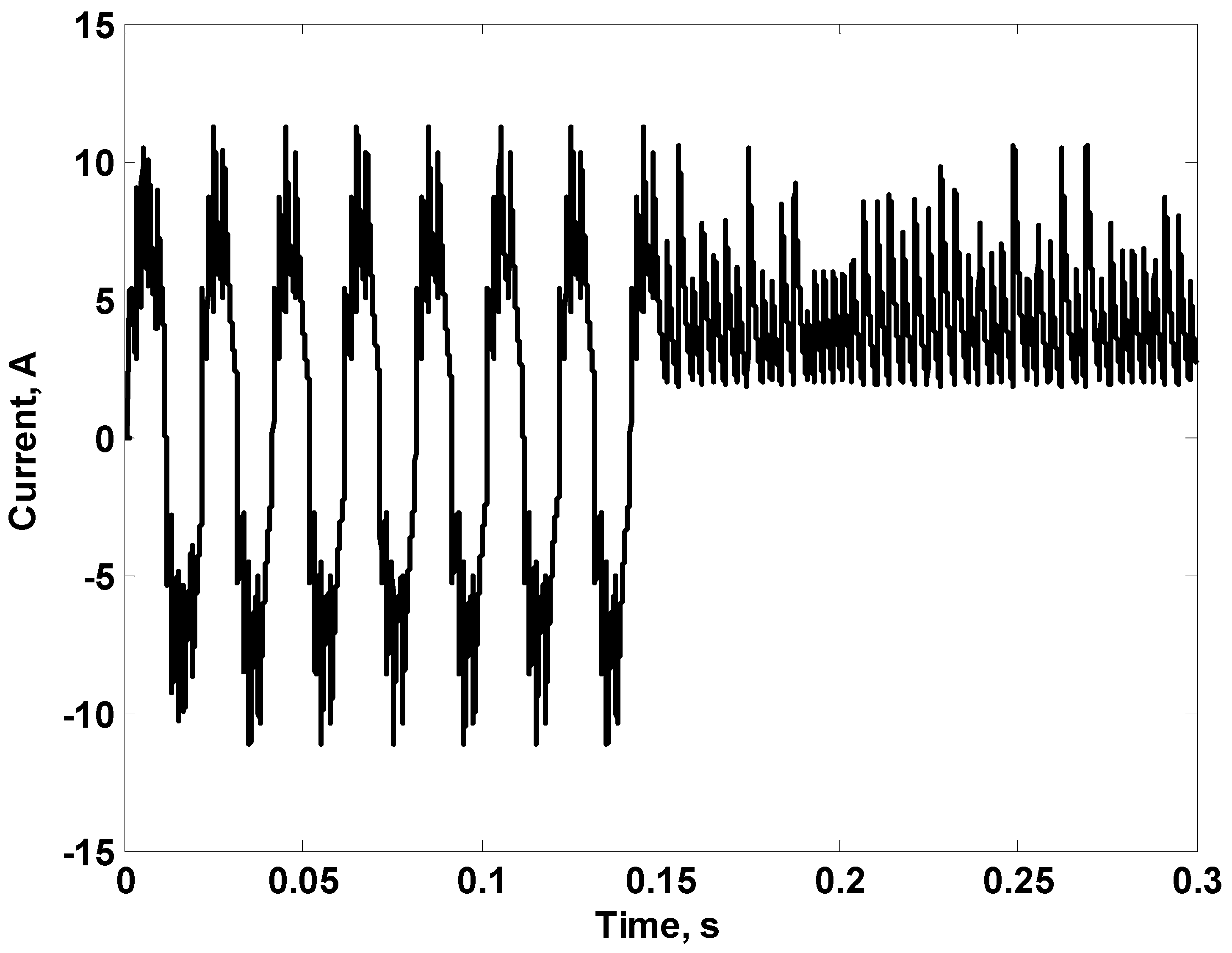
  • Studying the capability of the adopted converter to give sinusoidal variable voltages with variable frequencies.
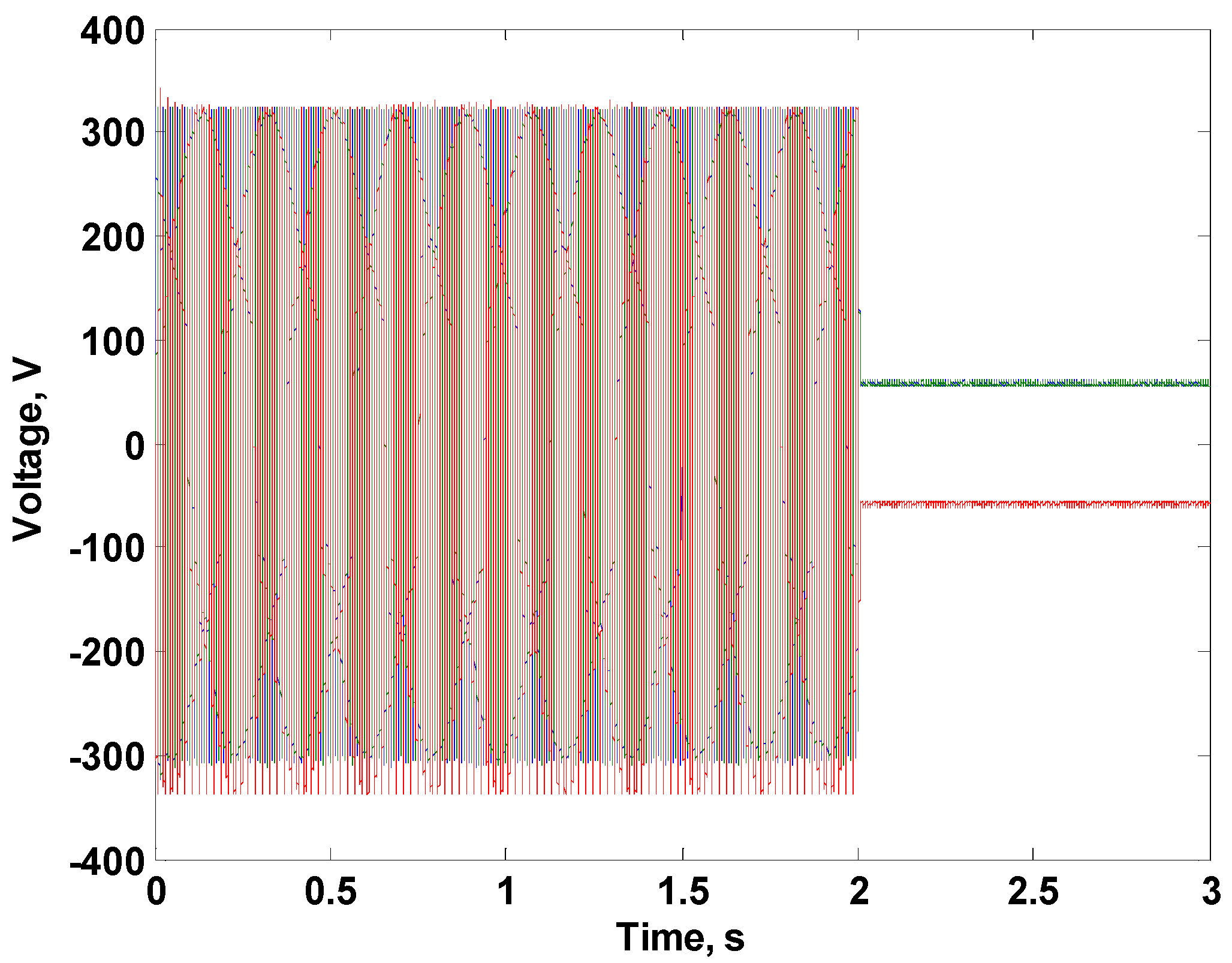
  • Studying the capability of the converter to give +ve as well as −ve DC voltages at its output terminals.
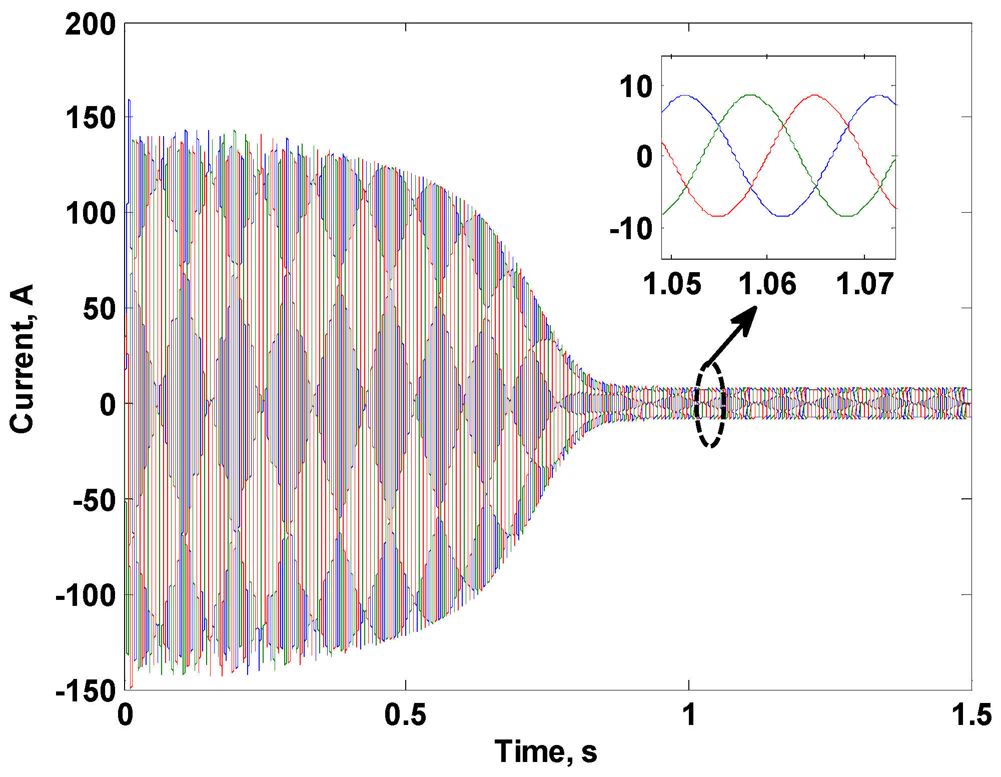
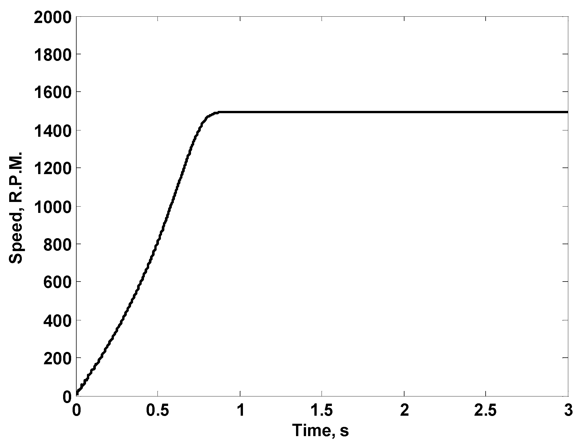
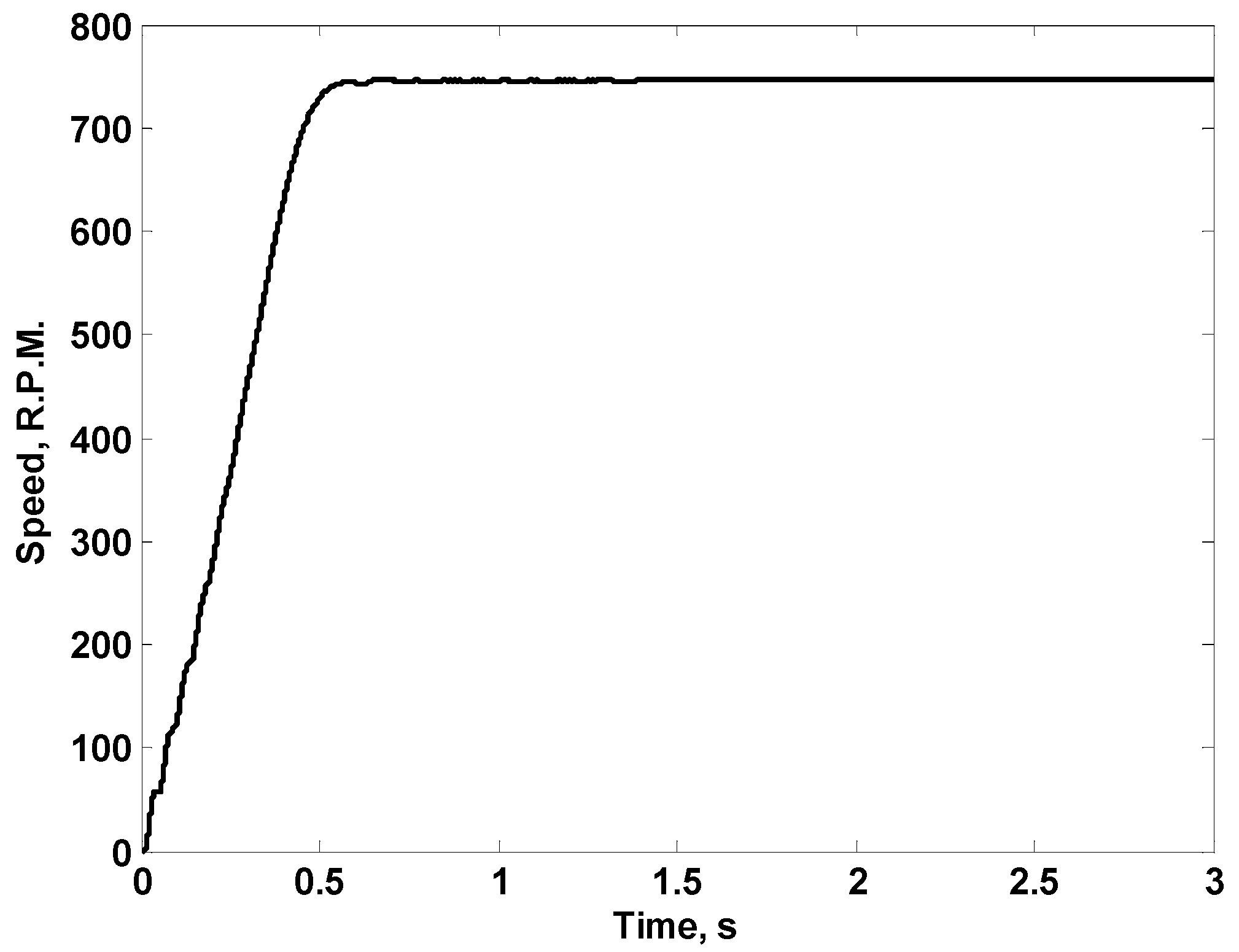
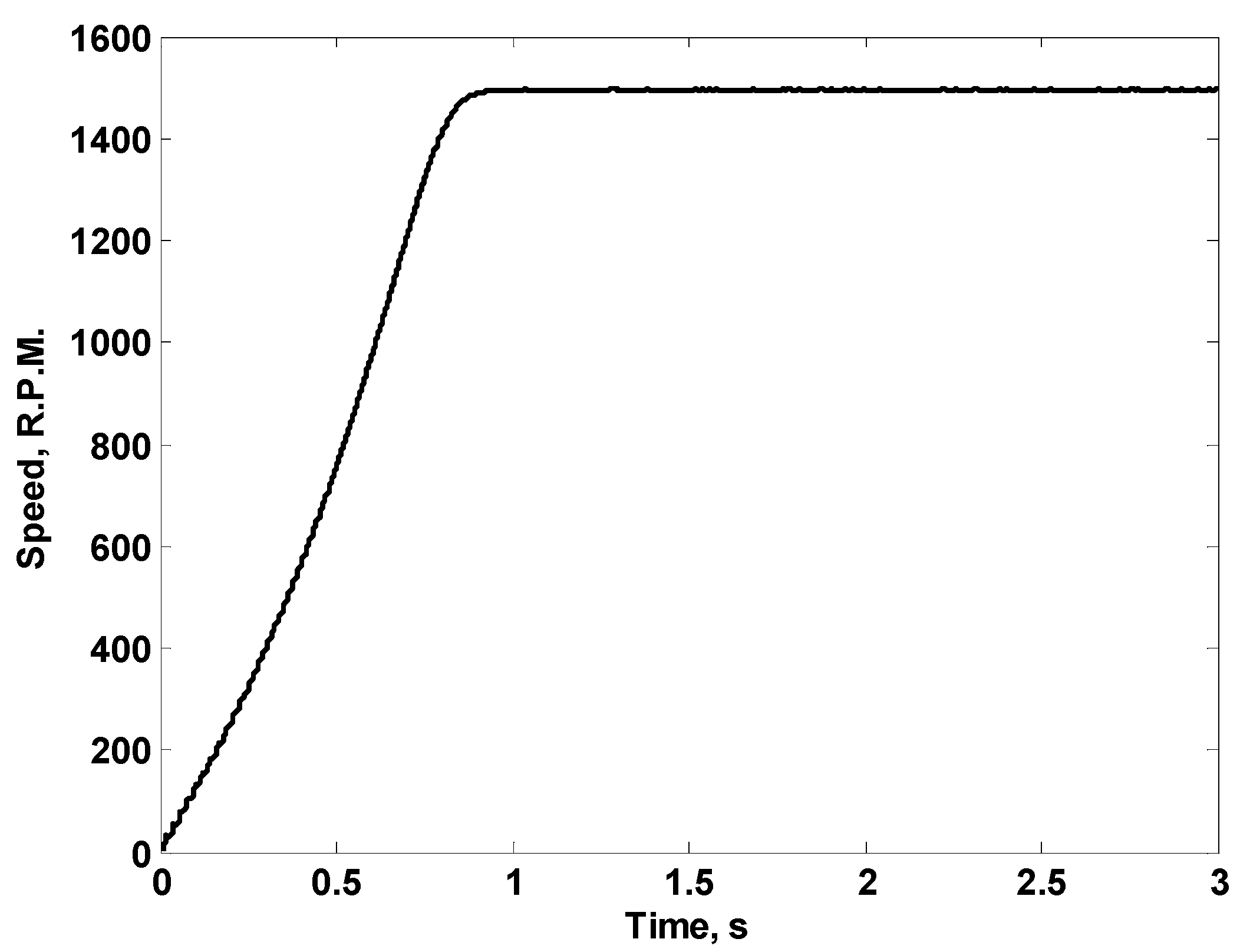
  • Using three suggested single-phase converters to drive a three-phase induction motor.
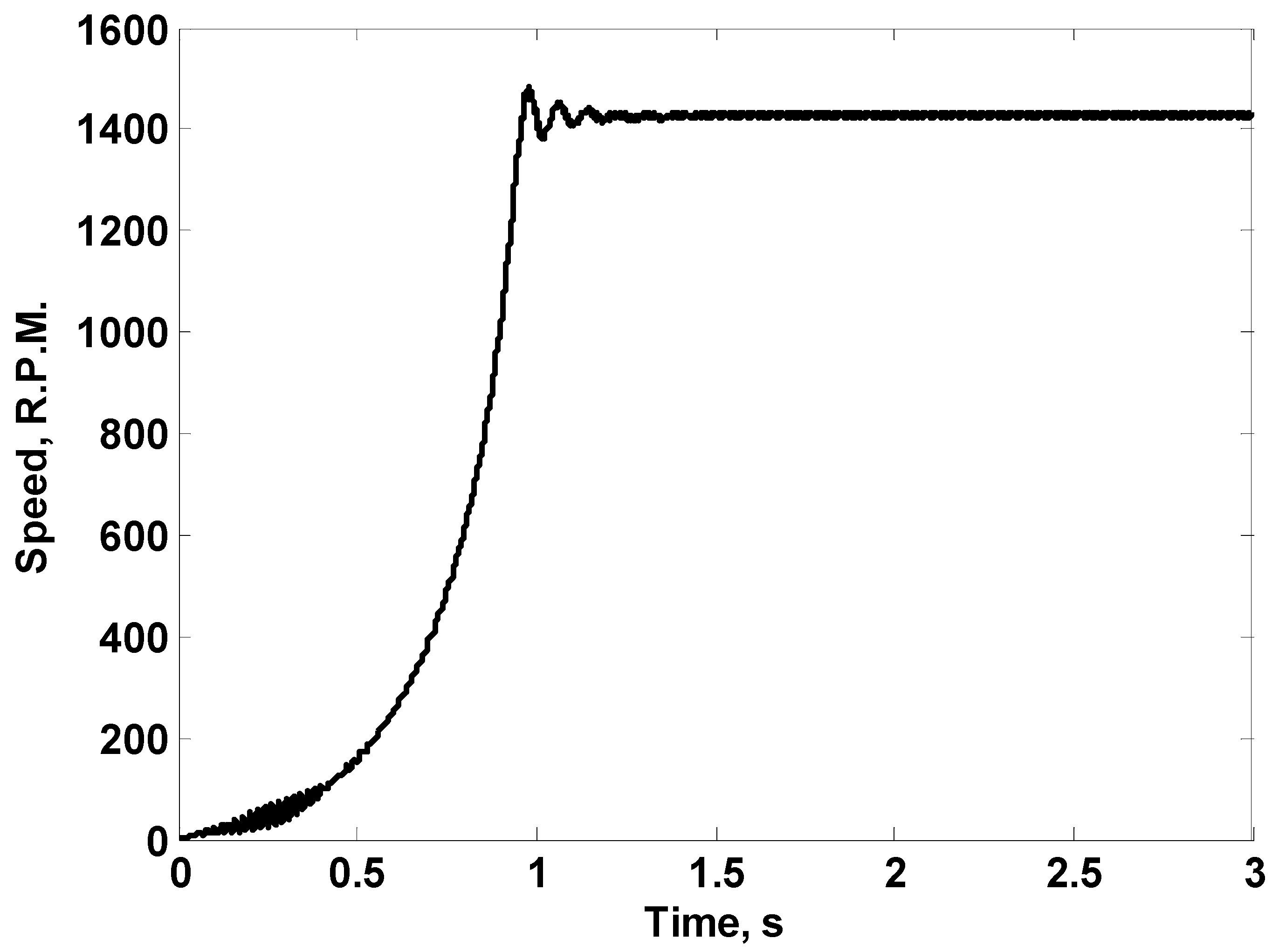
  • Studying the performance of the three-phase system with partial damage (part in one battery or some complete batteries) in the storage batteries as well as the occurrence of a fault in one phase of the induction motor phases.
The obtained results of the aforementioned cases are presented as follows.

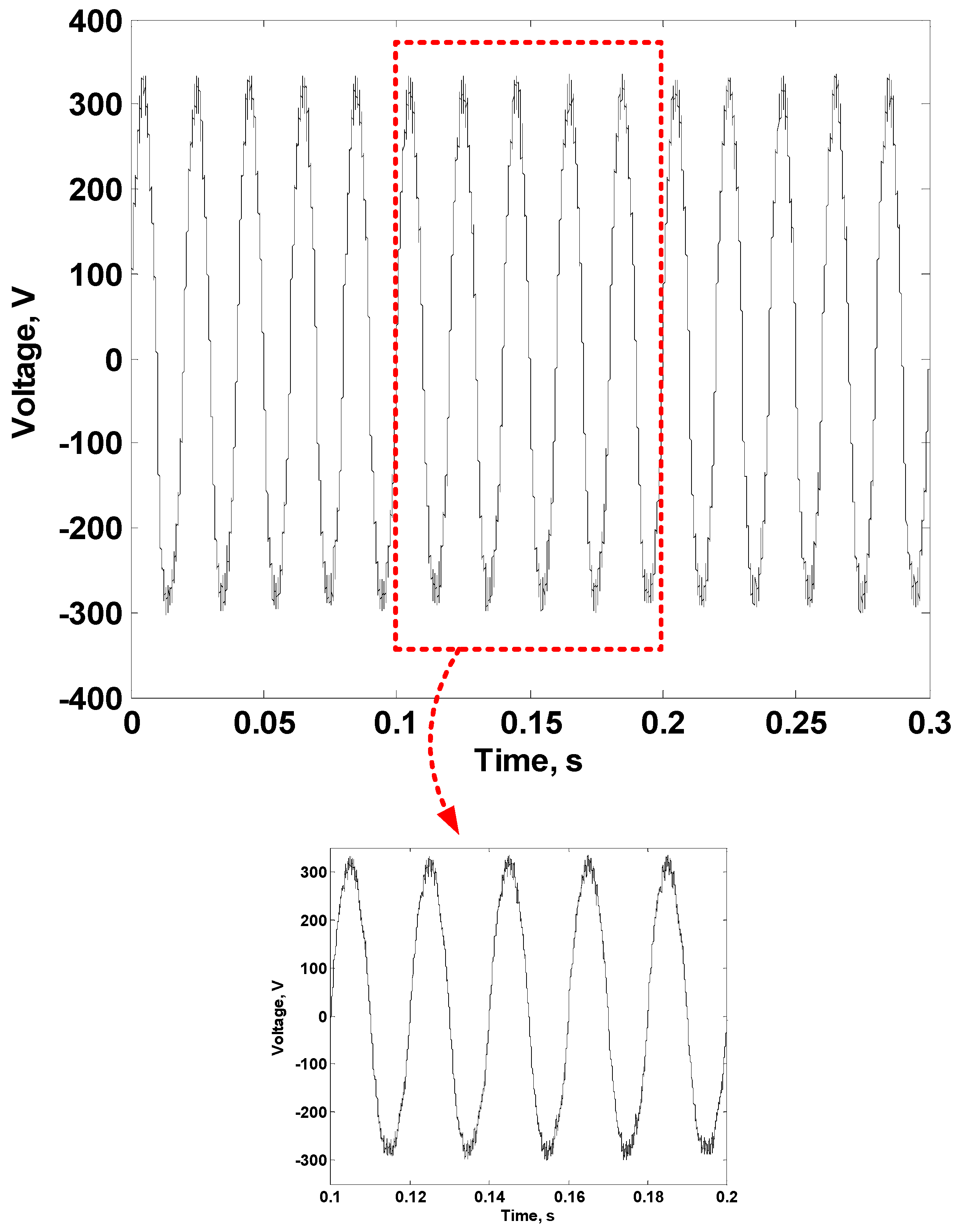
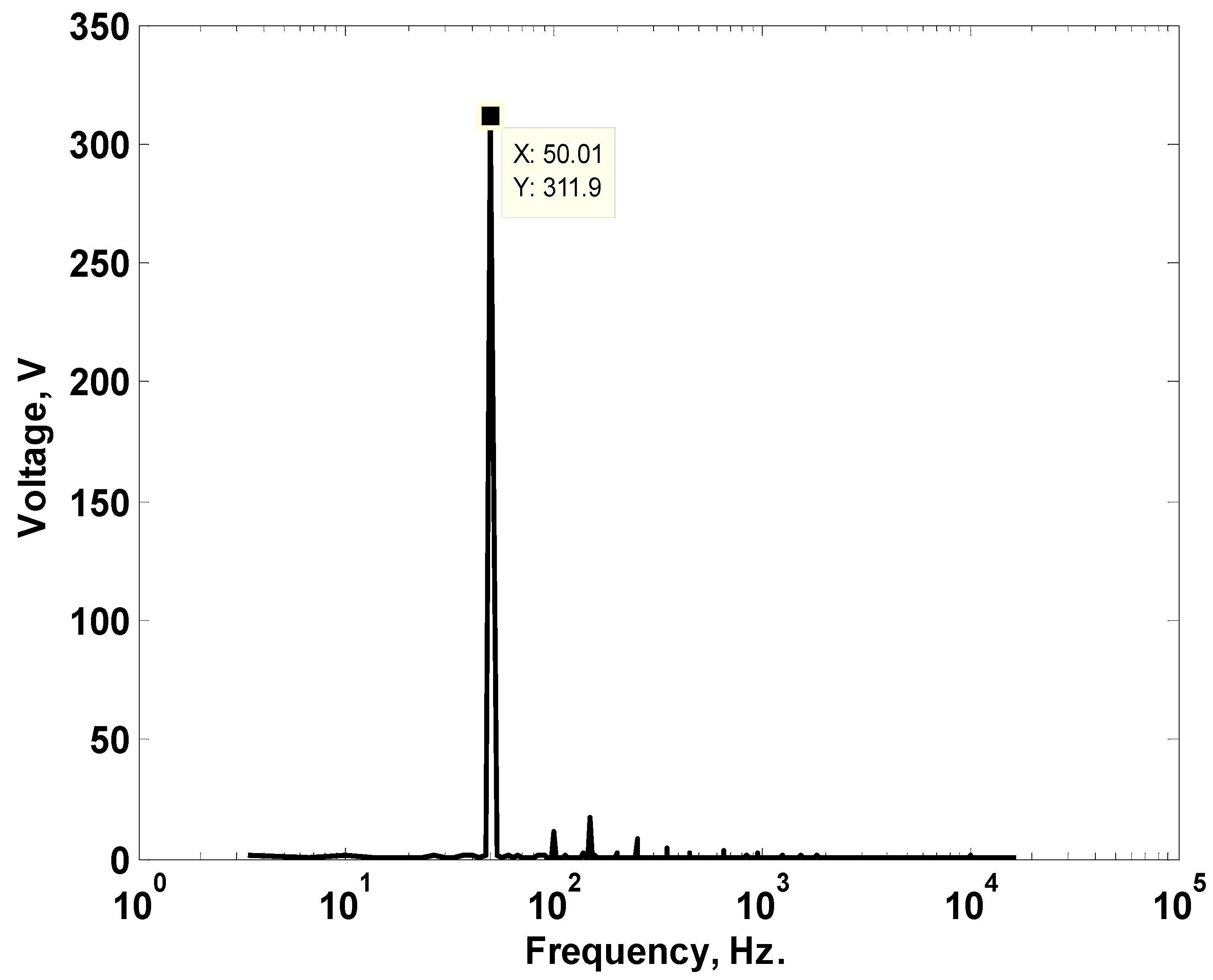
3.1. The Capability of the Converter to Give Siusoidal Voltages with Variable Amplitudes and Frequencies

The converter shown previously in Figure 5 is simulated with Power Simulation Program (PSIM) software, as displayed in Figure 8. The inductance (L) of the inductor used in the converter is taken to be equal 0.1 mH and its resistance is taken as 0.01 Ω. The capacitances of the left-hand side (C1) as well as the right-hand side (C2) capacitors are taken to be equal, with a value of 100 µF. The input DC voltage of the converter is taken to be 120 V. This means that twelve 12 V batteries are connected in series and used as an input source. The reference voltage is chosen to be 220 V R.M.S. (310 V peak). However, the frequency of the triangular wave used to generate the pulses is equal to 10 kHz. The adopted controller is chosen to be a Proportional-Derivative (PD) controller with a proportional gain of 15 and a time constant of 0.003.
Figure 9 shows the obtained output voltage (with 50 Hz frequency) considering an inductive load having a resistance of 15 Ω and an inductance of 30 mH. From the figure, the voltage is nearly sinusoidal, with its peak having a value of 312 V. This means that satisfactory performance is achieved, especially with the reduced harmonics content as displayed in Figure 10, which shows the Fast Fourier Transform (FFT) of the obtained voltage waveform. As the load is inductive, the harmonics content in the load current will be lower than the voltage waveform due to the effect of load inductance filtering, as shown in Figure 11 and Figure 12. To illustrate the capability of the adopted converter to give sinusoidal voltages with variable amplitudes and frequencies, another case is presented. The R.M.S. value of voltage for this case is chosen to be 110 V with a frequency of 25 Hz. In this case, only voltage and current waveforms (Figure 13 and Figure 14, respectively) are chosen to be presented as the same conclusions from the FFT curves are obtained. From all the obtained curves, the adopted buck–boost converter has a good performance to be used in electric vehicles.

3.2. The Capability of the Converter to Give +ve and −ve DC Voltages at Its Output

In this section, the same converter with the same simulated parameters is used. Firstly, the converter is simulated to give 220 V (R.M.S.) 50 Hz waveform for a period of 0.2 s using the same adopted technique adopted in Section 3.1. A transfer to obtain a +ve DC output voltage of 55 V is activated at 0.2 s until 0.3 s. The adopted control technique to obtain the DC voltage is illustrated in Figure 7. Figure 15 and Figure 16 show the output voltage and current waveforms, respectively, for this studied case. Furthermore, a similar case is simulated, but a DC voltage having a value of −100 V is activated at 0.2 s. The obtained output voltage and current waveforms for this case are shown in Figure 17 and Figure 18, respectively. The obtained AC voltage is nearly sinusoidal, with low distortion level, as well as the ripple in DC voltage being within the accepted limits. Therefore, the adopted converter can give +ve as well as −ve DC voltages with different magnitude levels at its output. This feature is used in this proposal to achieve DC braking of the three-phase induction motor that is used to drive the car instead of the conventional mechanical braking. In fact, there are other simulated cases considering different voltage levels as well as transfer from AC to DC voltages at different instants. All the obtained results validate the efficacy of the converter to transfer easily and efficiently between AC and DC voltages. These results are not shown here as the same conclusions from the presented figures are obtained. Furthermore, it is worth mentioning that the maximum error in the obtained DC voltage at the output terminals is found to be less than 2.3%. Finally, the DC current is found to be smoother compared to the DC voltage. This effect comes due to the impact of load inductance filtering.

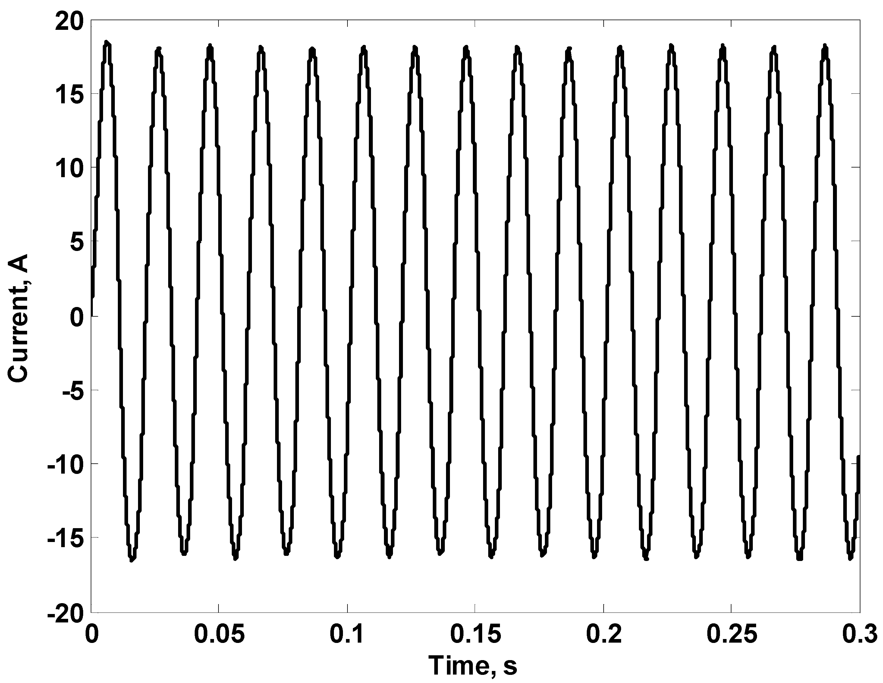
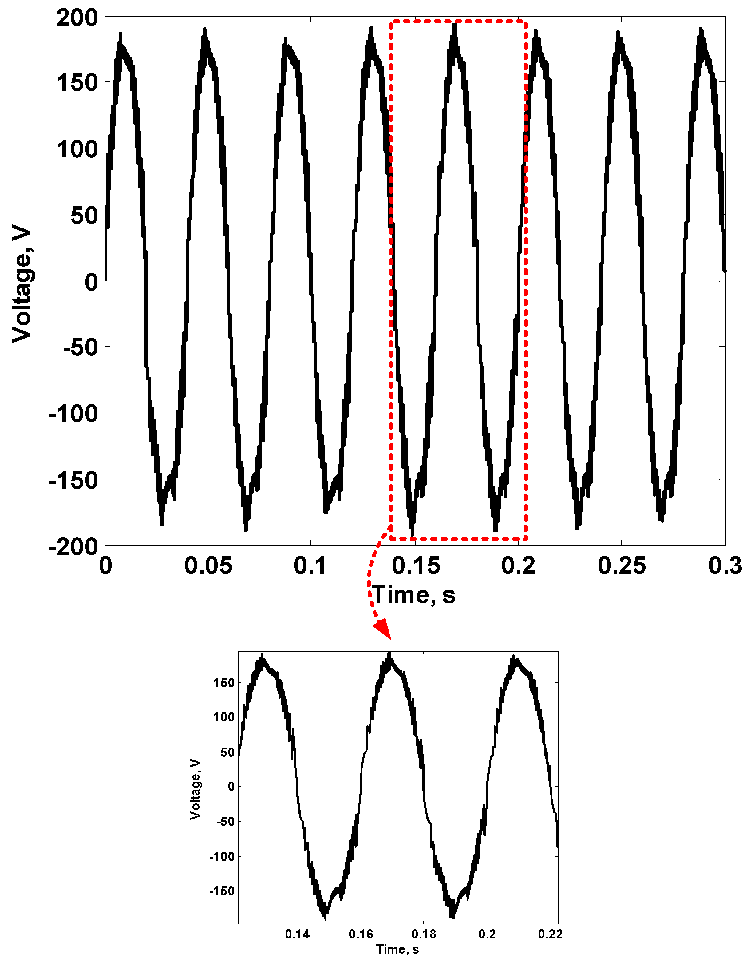
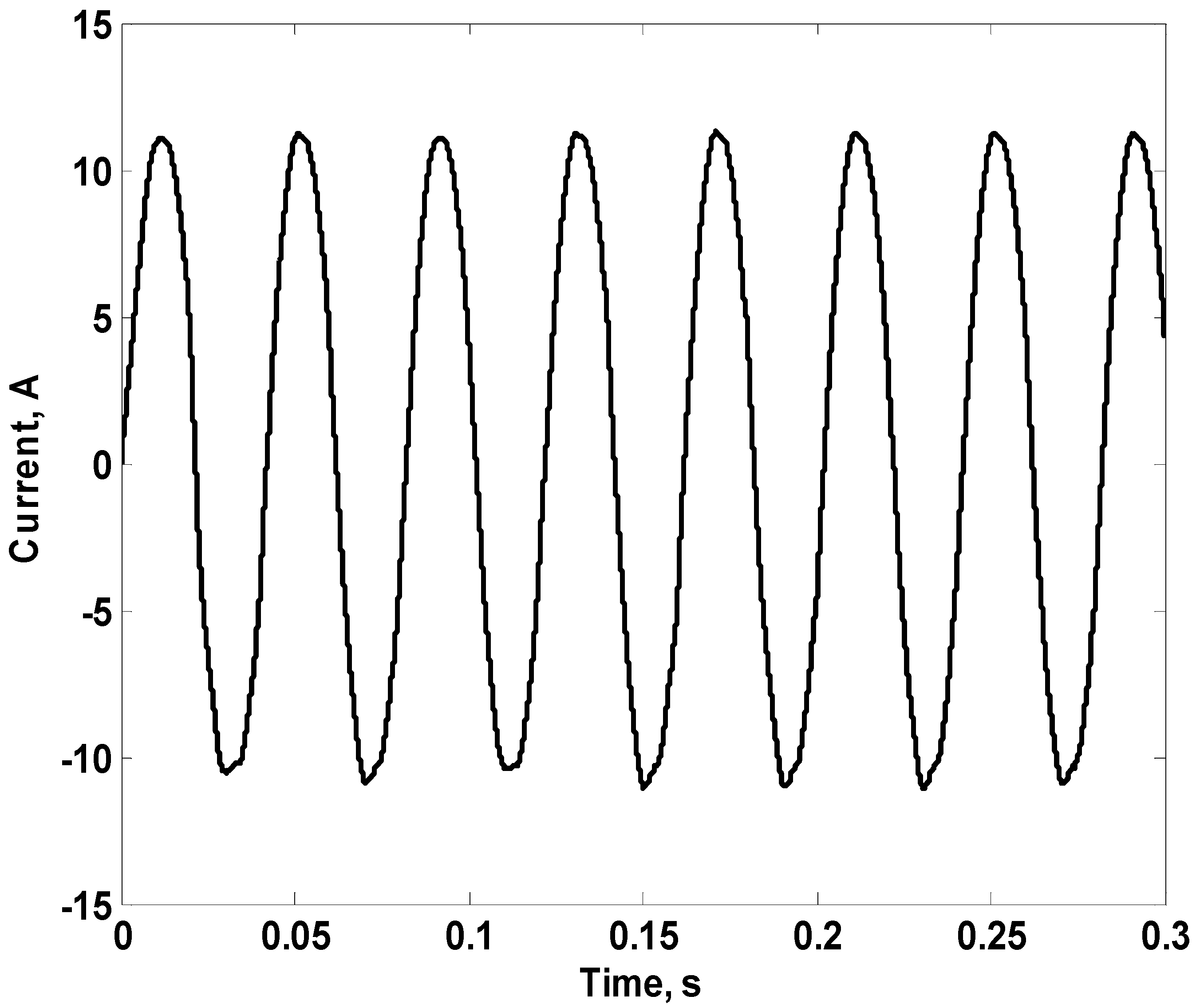
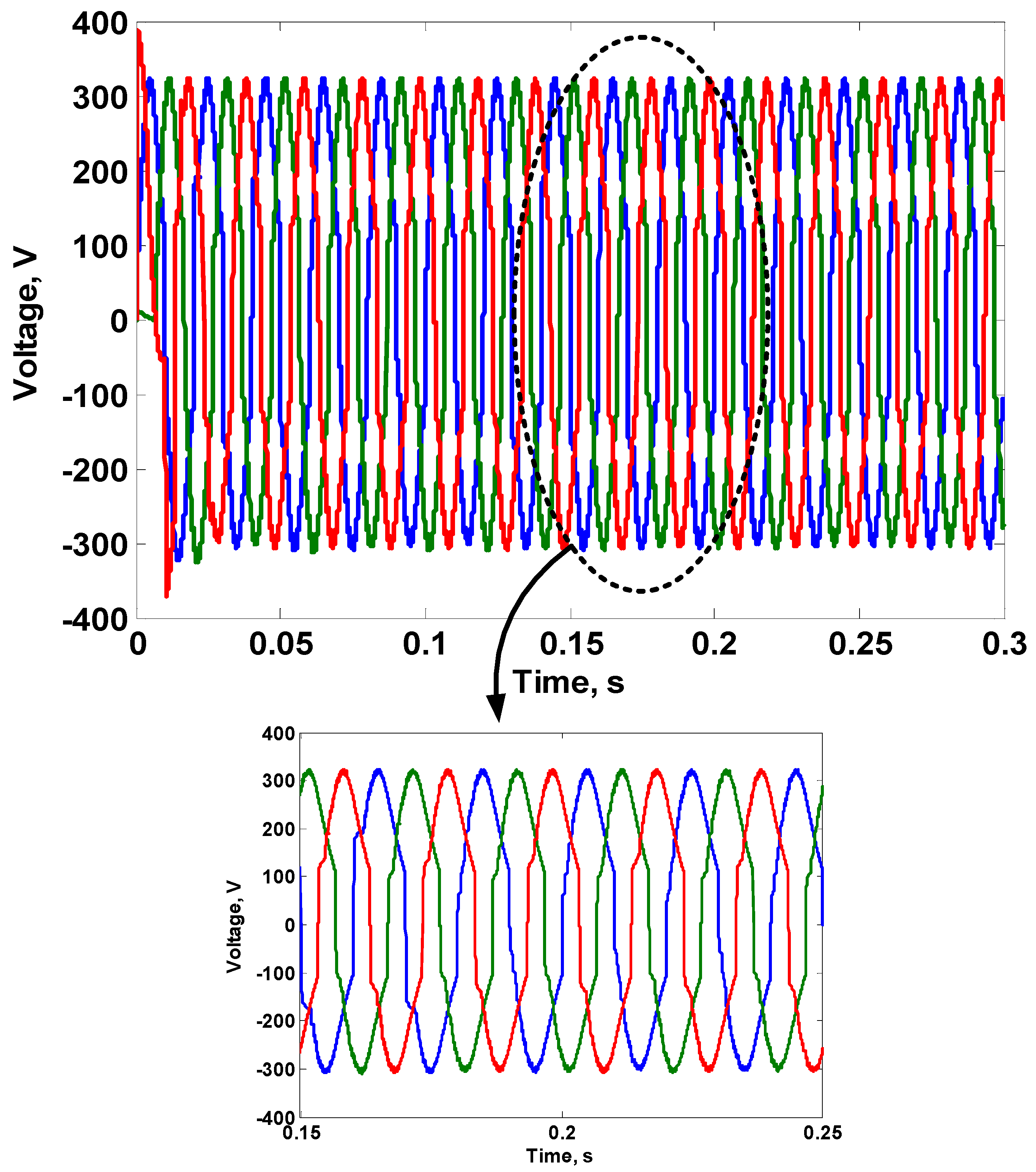
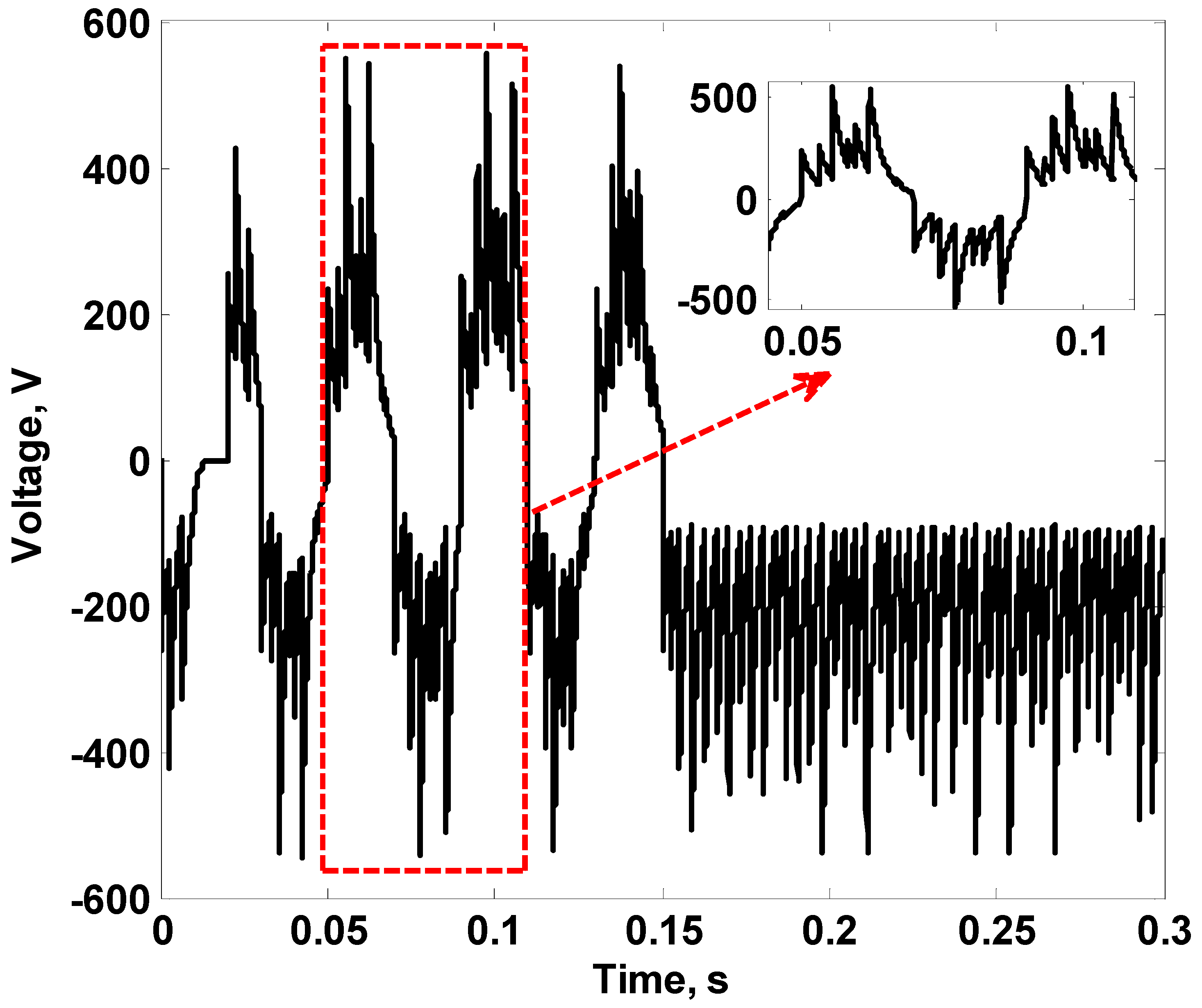
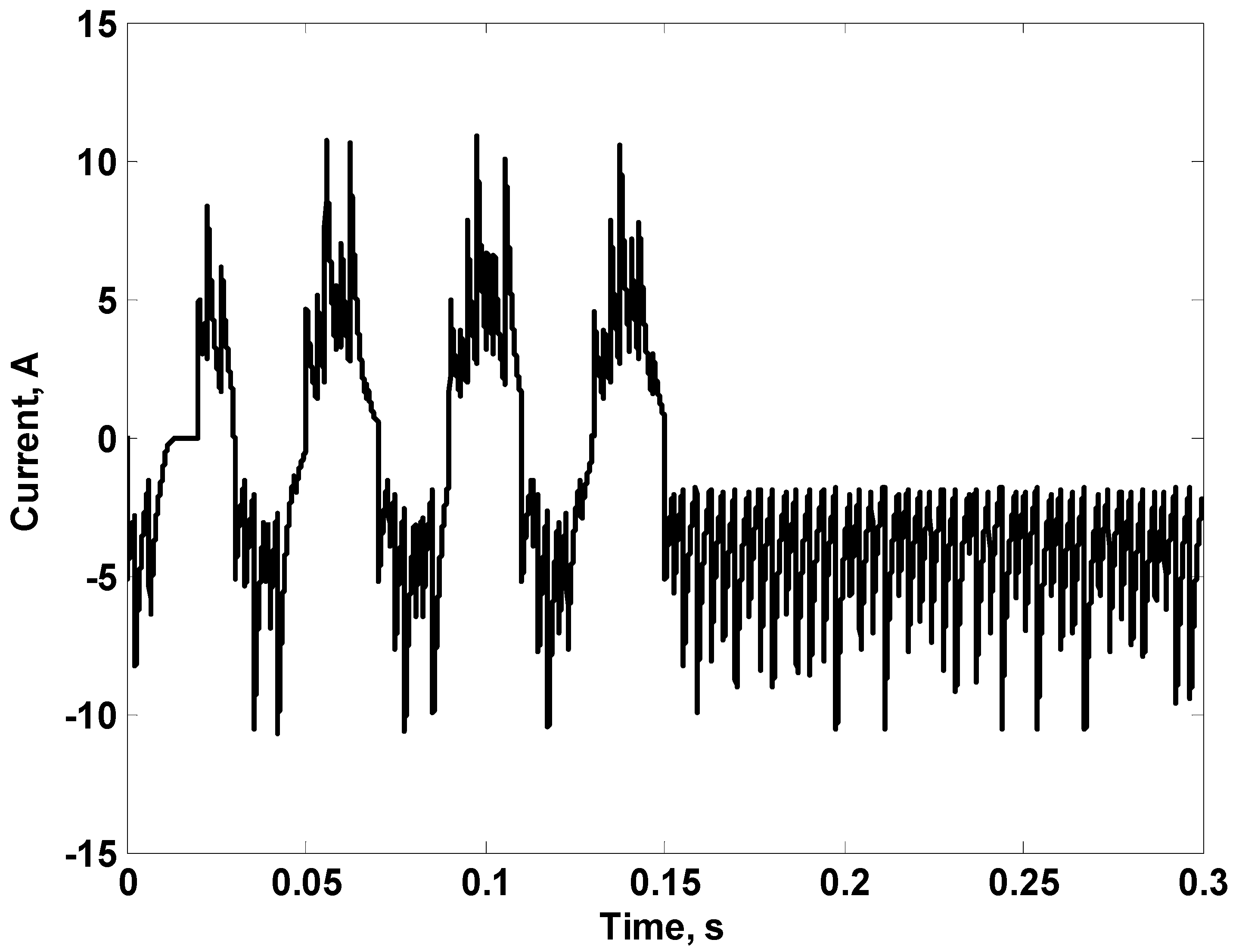
3.3. Three Single-Phase Converters to Drive a Three-Phase Motor

In this section, three single-phase converters are used to give three-phase excitation to a three-phase induction motor according to the schematic diagram shown previously in Figure 4, to allow each converter to feed a separate phase. In this case, phase shifts in the reference signals are carried out. This is carried out to produce 120° phase shift between each two consecutive phases. This procedure can be easily carried out with the adopted control technique. Hence, the phase angle of the reference signal used in the control loop of the phase-A converter is set at 0°, while the phase angles of the reference signals used with phase-B and phase-C converters are set at −120° and 120°, respectively. The parameters of the induction motor used in simulation are listed in Table 1. The motor load is chosen to be constant (10 N·m), to simulate a car with a fixed load and runs at a constant speed.
Figure 19 shows the applied three-phase voltages on the motor windings considering 220 V, 50 Hz waveform. The three-phase currents drawn by the motor are shown in Figure 20 and the motor speed is shown in Figure 21. To obtain a lower car speed, the frequency of the output voltage is reduced and accordingly the applied voltage must be reduced to achieve a constant V/f ratio. In Figure 22, Figure 23 and Figure 24, motor applied voltages, phase currents, and motor speed are shown, respectively, considering an applied voltage of 110 V with a frequency of 25 Hz. From all these figures, the applied voltages as well as the motor phase currents are nearly sinusoidal. Furthermore, it can be seen that the adopted technique can drive the three-phase induction motor with the required performance. To illustrate the suitability of the adopted technique to provide motor braking, a DC voltage is applied from the same converter to each phase to stop the motor without the need for a mechanical braking system. In our study, +ve equal DC voltages are applied to motor phases A and B. However, a −ve DC voltage with the same value of +ve DC is applied to phase-C of the motor. This technique for excitation is found to give the highest braking torque with respect to the braking current. The value of DC voltage is chosen to be 55 V (about 25% of the rated phase voltage) to limit the increase in motor currents during the braking process, to increase the driving motor lifetime. Figure 25 and Figure 26 show the applied motor voltages and the motor speed, respectively, considering the adopted braking technique. From these figures, the suggested drive technique can provide braking of the motor car efficiently, especially with its ability to drive the motor under some fault conditions, which increase the system reliability as shown in the next subsections.

3.4. Performance of the Three-Phase System with Partial Damage in the Storage Batteries or Fault Occurrence in One Phase of the Motor

One of the great advantages of the adopted converter is its ability to buck and boost the input voltage. Therefore, if partial damage occurs in the storage batteries, it can adjust the output voltage to the level required to drive the motor car. For example, if damage in two batteries occurs, the input DC voltage of the converter can lose 24 V. Therefore, it will be 96 V instead of 120 V. In fact, the adopted control technique in conjunction with the adopted converter can deal with this problem. This is shown in Figure 27, which shows the output voltage under this condition. The peak value of the output voltage is found to be 304.8 V (216 V R.M.S.). This means that only a decrease by 1.8% compared to the desired rated voltage is obtained. This decrease is acceptable and does not affect the motor performance; hence, the motor speed decreases only by less than 0.2% of its rated value at the same load, as shown in Figure 28. Furthermore, one of the main other advantages of the suggested drive system is its ability to drive the motor driving the car during the occurrence of an open circuit in one of its phases. Hence, with the occurrence of an open circuit in one of the motor phases, the other two phases can produce a rotating magnetic field, as there is an angle of 120° between the two phases in addition to the presence of 120° phase shift between their currents, as shown in Figure 29. It is noticed that the motor speed under this condition (open-circuited phase) decreases by less than 1.2% and a slight increase in the time to reach steady state occurs, as shown in Figure 30. The slight increase in the required time to reach steady-state speed comes due to the reduction in the motor starting torque due to a loss in one of the motor phases. Therefore, using the suggested drive system with golf cars can increase the system reliability and improve its performance. Although an increase in the motor current is observed with the same load, this feature can be very useful as it helps in driving the car (with reduced load) until its maintenance is performed.

4. Experimental Results

In this section, a prototype of the single-phase of the adopted converter is built. The converter is built using four IGBTs (Model CM300DY-24A Mitsubishi Electric). The used inductance of the converter (L) is equal to 1 mH. However, the used capacitance (C1 or C2) is equal to 47 µF. The values of converter inductance and capacitances are chosen to obtain a satisfactory performance with the used switching frequency. The same control technique adopted in simulation with the same parameters is used to investigate the performance of the converter with 50 Ω, 1 mH load. The control technique is implemented using a DSP-board dSpace 1104 and the capacitor voltage used in the control loop is measured using a voltage transducer. The frequency of the triangular waveform used in the control loop to generate the control pulses is 3 kHz. This frequency is used due to limitations in the sampling frequency of the used DSP. The input voltage is supplied from a 120 V DC source. Figure 31 shows a photograph presenting the details of the experimental setup used in this study.
Figure 32 shows the obtained output voltage when the reference signal is adjusted at 220 V, 50 Hz with a transfer to a DC signal of 200 V at 0.15 s. Figure 33 shows the current waveform obtained under this condition. Furthermore, Figure 34 shows the terminal voltage when the reference signal is adjusted at 110 V, 25 Hz with a transfer to a DC signal of −200 V at 0.15 s, and the obtained current under these conditions is shown in Figure 35. From the obtained experimental results, the capability of the adopted converter to give AC voltages at different frequencies as well as DC voltages (either +ve or −ve) is illustrated. Furthermore, the obtained AC voltages at the converter terminals can be shaped to be nearly sinusoidal. However, the presence of some distortion in the AC voltage waveforms and some ripples in the DC voltage waveforms can be reduced by increasing the frequency of the triangular waveform used to generate the control pulses. Generally, the obtained performance is satisfactory. Therefore, it can be recommended for use in the suggested applications and other applications that need its features. Furthermore, the efficacy of the adopted control technique is validated.

5. Conclusions

A suggested drive system for a golf car has been presented. The performance of the suggested drive system has been studied through simulation using PSIM software. The performance study has been carried out considering different cases. These cases are motoring at healthy condition as well as at the occurrence of some faults in batteries or in the motor itself. Furthermore, braking of the driving three-phase induction motor using DC voltage has been carried out. The efficacy of the adopted converter is evaluated through experimental work. Generally, the following points can be concluded:
  • The suggested system has the advantage of high reliability, as it can deal with different fault conditions such as battery and motor winding faults.
  • The suggested electric drive system depends on a buck–boost converter which has the ability to give variable voltages as well as variable frequencies.
  • Variable speeds of the electric vehicles can be easily achieved due to the ability of the adopted converter to give variable voltages at variable frequencies.
  • The adopted converter can give a variable DC voltage (positive or negative) at its output. This DC voltage can be used to achieve braking of the induction motor used in the electric vehicle to avoid the use of ordinary mechanical braking, increasing the vehicle’s reliability.

Author Contributions

Conceptualization, M.S.E., M.E.I., E.T.E., H.Y.H., S.A. and E.E.E.-K.; Investigation, M.S.E.; Methodology, M.S.E., M.E.I., E.T.E., H.Y.H., S.A. and E.E.E.-K.; Software, M.S.E.; Supervision, M.E.I., E.T.E., H.Y.H. and E.E.E.-K.; Validation, M.E.I., H.Y.H., S.A. and E.E.E.-K.; Writing—original draft, M.S.E.; Writing—review and editing, M.S.E., M.E.I., E.T.E., H.Y.H., S.A. and E.E.E.-K. All authors have read and agreed to the published version of the manuscript.

Funding

This research received no external funding.

Conflicts of Interest

The authors declare that they have no known competing financial interest or personal relationships that could have appeared to influence the work reported in this paper.

References

  1. Sanguesa, J.A.; Torres-Sanz, V.; Garrido, P.; Martinez, F.J.; Marquez-Barja, J.M. A Review on Electric Vehicles: Technologies and Challenges. Smart Cities 2021, 4, 372–404. [Google Scholar] [CrossRef]
  2. Hawkins, T.R.; Gausen, O.M.; Strømman, A.H. Environmental impacts of hybrid and electric vehicles—A review. Int. J. Life Cycle Assess. 2012, 17, 997–1014. [Google Scholar] [CrossRef]
  3. Vasant, P.; Marmolejo, J.A.; Litvinchev, I.; Aguilar, R.R. Nature-inspired meta-heuristics approaches for charging plug-in hybrid electric vehicle. Wirel. Netw. 2019, 26, 4753–4766. [Google Scholar] [CrossRef]
  4. European Commission. Transport in Figures’—Statistical Pocketbook. 2011. Available online: https://ec.europa.eu/transport/facts-fundings/statistics/pocketbook-2011_en/ (accessed on 21 February 2021).
  5. Chan, C.C. The State of the Art of Electric, Hybrid, and Fuel Cell Vehicles. Proc. IEEE 2007, 95, 704–718. [Google Scholar] [CrossRef]
  6. Albatayneh, A.; Assaf, M.N.; Alterman, D.; Jaradat, M. Comparison of the Overall Energy Efficiency for Internal Combustion Engine Vehicles and Electric Vehicles. Environ. Clim. Technol. 2020, 24, 669–680. [Google Scholar] [CrossRef]
  7. Yong, J.Y.; Ramachandaramurthy, V.K.; Tan, K.M.; Mithulananthan, N. A review on the state-of-the-art technologies of electric vehicle, its impacts and prospects. Renew. Sustain. Energy Rev. 2015, 49, 365–385. [Google Scholar] [CrossRef]
  8. Thiel, C.; Perujo, A.; Mercier, A. Cost and CO2 aspects of future vehicle options in Europe under new energy policy scenarios. Energy Policy 2010, 38, 7142–7151. [Google Scholar] [CrossRef]
  9. Richardson, D.B. Electric vehicles and the electric grid: A review of modeling approaches, Impacts, and renewable energy integration. Renew. Sustain. Energy Rev. 2013, 19, 247–254. [Google Scholar] [CrossRef]
  10. Habib, S.; Kamran, M.; Rashid, U. Impact analysis of vehicle-to-grid technology and charging strategies of electric vehicles on distribution networks—A review. J. Power Sources 2015, 277, 205–214. [Google Scholar] [CrossRef]
  11. Shuai, W.; Maille, P.; Pelov, A. Charging Electric Vehicles in the Smart City: A Survey of Economy-Driven Approaches. IEEE Trans. Intell. Transp. Syst. 2016, 17, 2089–2106. [Google Scholar] [CrossRef] [Green Version]
  12. Tan, K.M.; Ramachandaramurthy, V.K.; Yong, J.Y. Integration of electric vehicles in smart grid: A review on vehicle to grid technologies and optimization techniques. Renew. Sustain. Energy Rev. 2016, 53, 720–732. [Google Scholar] [CrossRef]
  13. Hu, J.; Morais, H.; Sousa, T.; Lind, M. Electric vehicle fleet management in smart grids: A review of services, optimization and control aspects. Renew. Sustain. Energy Rev. 2016, 56, 1207–1226. [Google Scholar] [CrossRef]
  14. Rahman, I.; Vasant, P.M.; Singh, B.S.M.; Abdullah-Al-Wadud, M.; Adnan, N. Review of recent trends in optimization techniques for plug-in hybrid, and electric vehicle charging infrastructures. Renew. Sustain. Energy Rev. 2016, 58, 1039–1047. [Google Scholar] [CrossRef]
  15. Das, H.; Rahman, M.; Li, S.; Tan, C. Electric vehicles standards, charging infrastructure, and impact on grid integration: A technological review. Renew. Sustain. Energy Rev. 2020, 120, 109618. [Google Scholar] [CrossRef]
  16. Emadi, A.; Lee, Y.J.; Rajashekara, K. Power Electronics and Motor Drives in Electric, Hybrid Electric, and Plug-In Hybrid Electric Vehicles. IEEE Trans. Ind. Electron. 2008, 55, 2237–2245. [Google Scholar] [CrossRef]
  17. Ehsani, M.; Gao, Y.; Miller, J.M. Hybrid Electric Vehicles: Architecture and Motor Drives. Proc. IEEE 2007, 95, 719–728. [Google Scholar] [CrossRef]
  18. Chakraborty, S.; Vu, H.-N.; Hasan, M.M.; Tran, D.-D.; El Baghdadi, M.; Hegazy, O. DC-DC Converter Topologies for Electric Vehicles, Plug-in Hybrid Electric Vehicles and Fast Charging Stations: State of the Art and Future Trends. Energies 2019, 12, 1569. [Google Scholar] [CrossRef]
  19. Metwaly, M.K.; Alsharef, M.; Sabiha, N.A.; Elattar, E.E.; Taha, I.B.M.; Abd-Elhady, A.M.; Elkalashy, N.I. Smart integration of drive system for induction motor applications in electric vehicles. Int. J. Power Electron. Drive Syst. (IJPEDS) 2021, 12, 20–28. [Google Scholar] [CrossRef]
  20. Ibrahim, M.E.; Mansour, A.S.; Abd-Elhady, A.M. A novel single-stage single-phase buck–boost inverter. Electr. Eng. 2017, 99, 345–356. [Google Scholar] [CrossRef]
Figure 1. Golf car uses PV panels to charge its batteries in addition to charging from utility.
Energies 15 06469 g001
Figure 2. Golf car drive system.
Energies 15 06469 g002
Figure 3. Suggested Golf car drive system.
Energies 15 06469 g003
Figure 4. The Adopted Buck–Boost DC–AC Converter Feeding a 3-Phase Induction Motor.
Energies 15 06469 g004
Figure 5. The Adopted Buck–Boost DC–AC Converter Circuit Diagram.
Energies 15 06469 g005
Figure 6. The Adopted Control Technique of the DC–AC Buck–Boost Converter.
Energies 15 06469 g006
Figure 7. The Adopted Control Technique to Obtain +ve DC Voltage at the Output of the Adopted Converter.
Energies 15 06469 g007
Figure 8. Simulated Single-Phase Buck–Boost Converter using PSIM Software.
Energies 15 06469 g008
Figure 9. Conditions of 220 V, 50 Hz Sinusoidal Output Voltage.
Energies 15 06469 g009
Figure 10. FFT of the Voltage Waveform Shown in Figure 8.
Energies 15 06469 g010
Figure 11. A 50 Hz Load Current.
Energies 15 06469 g011
Figure 12. FFT of the Current Waveform Shown in Figure 10.
Energies 15 06469 g012
Figure 13. Conditions of 110 V, 25 Hz Sinusoidal Output Voltage.
Energies 15 06469 g013
Figure 14. A 25 Hz Load Current.
Energies 15 06469 g014
Figure 15. Output Voltage with +ve DC transfer at Converter Terminals.
Energies 15 06469 g015
Figure 16. Output Current with +ve DC transfer at Converter Terminals.
Energies 15 06469 g016
Figure 17. Output Voltage with −ve DC transfer at Converter Terminals.
Energies 15 06469 g017
Figure 18. Output Current with −ve DC transfer at Converter Terminals.
Energies 15 06469 g018
Figure 19. Conditions of 220 V, 50 Hz 3-Phase Applied Voltage at the Motor Terminals.
Energies 15 06469 g019
Figure 20. Three-Phase Motor Currents when Excited with 220 V, 50 Hz.
Energies 15 06469 g020
Figure 21. Motor Speed when Excited with 220 V, 50 Hz.
Energies 15 06469 g021
Figure 22. Conditions of 110 V, 25 Hz 3-Phase Applied Voltage at the Motor Terminals.
Energies 15 06469 g022
Figure 23. Three-Phase Motor Currents when Excited with 110 V, 25 Hz.
Energies 15 06469 g023
Figure 24. Motor Speed when Excited with 110 V, 25 Hz.
Energies 15 06469 g024
Figure 25. Applied Voltage on the 3-Phase Induction Motor, Braking Occurs at 2 s.
Energies 15 06469 g025
Figure 26. Motor Speed, Braking Occurs at 2 s.
Energies 15 06469 g026
Figure 27. Three-Phase Voltages at Motor Terminals during Two-Battery Failure.
Energies 15 06469 g027
Figure 28. Three-Phase Motor Speed during Two-Battery Failure.
Energies 15 06469 g028
Figure 29. Motor Currents with an Open-Circuit in one of the Motor Phases.
Energies 15 06469 g029
Figure 30. Motor Speed with an Open-Circuit in one of the Motor Phases.
Energies 15 06469 g030
Figure 31. A Photograph of the Components Used in the Experimental Work.
Energies 15 06469 g031
Figure 32. Conditions of 220 V, 50 Hz with a Transfer to a DC Signal of 200 V at 0.15 s.
Energies 15 06469 g032
Figure 33. Obtained Current when the Reference Signal is Adjusted at 220 V, 50 Hz with a transfer to a DC signal of 200 V at 0.15 s.
Energies 15 06469 g033
Figure 34. Conditions of 110 V, 25 Hz with a Transfer to a DC Signal of −200 V at 0.15 s.
Energies 15 06469 g034
Figure 35. Obtained Current when the Reference Signal is Adjusted at 110 V, 25 Hz with a transfer to a DC signal of −200 V at 0.15 s.
Energies 15 06469 g035
Table 1. Parameters of the Simulated 3-Phase Induction Motor.
ParameterValueUnit
Stator Resistance0.294
Stator Inductance0.00139H
Rotor Resistance0.156
Rotor Inductance0.00074H
Magnetizing Inductance0.041H
No. of Poles4-
Moment of Inertia0.2kg·m2
Publisher’s Note: MDPI stays neutral with regard to jurisdictional claims in published maps and institutional affiliations.

