
Literature Review of Energy Management in Combined Heat and Power Systems Based on High-Temperature Proton Exchange Membrane Fuel Cells for Residential Comfort Applications


Abstract
:1. Introduction
2. Fuel Cell Technologies
3. Proton Exchange Membrane Fuel Cells
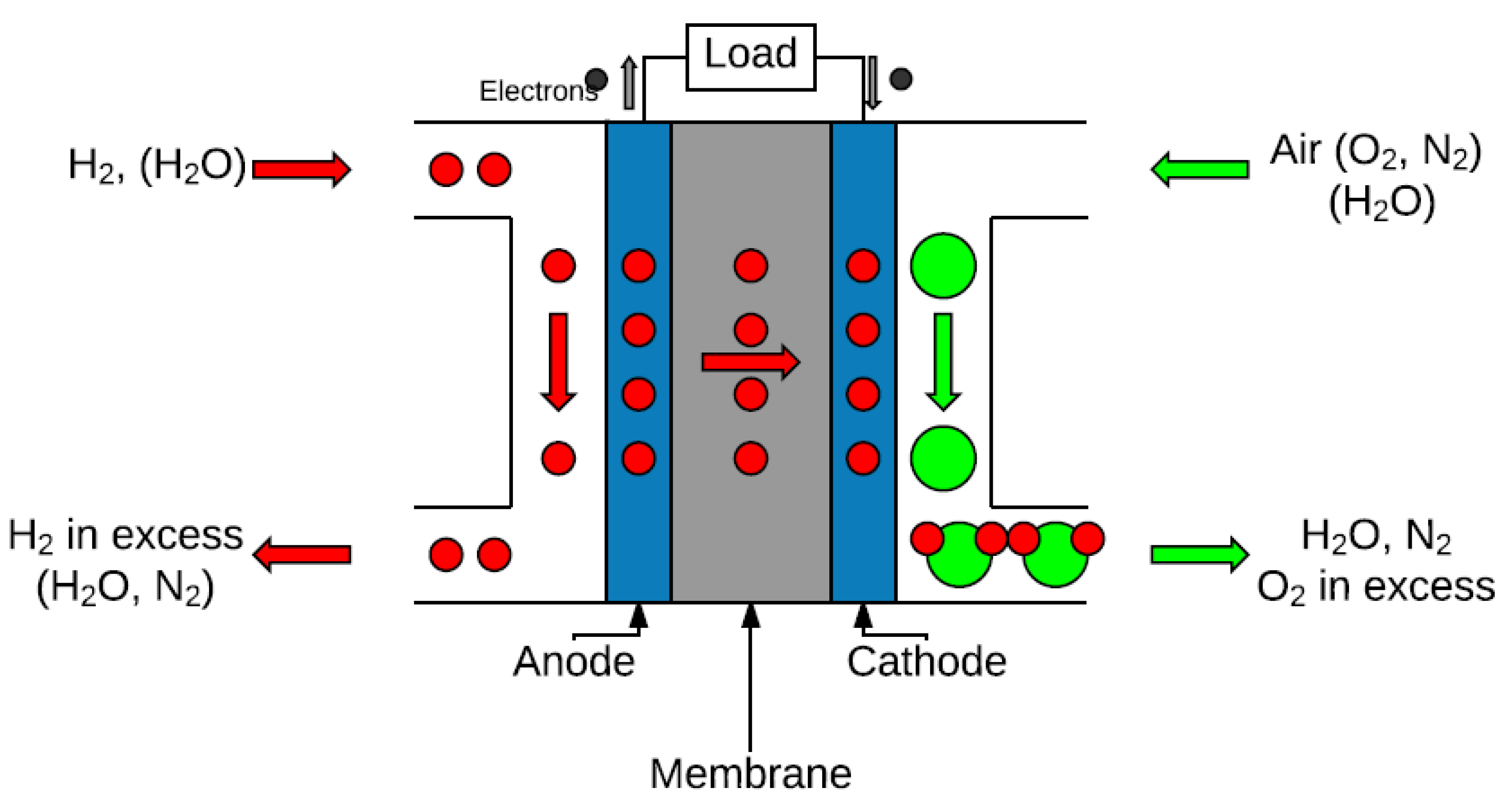
- Anode: corresponding to the left part of Figure 2. Fuel in the shape of gas goes through these pores to reach the interface with the electrolyte, responsible for conducting ions and the place where fuel oxidises; electrons move across an external circuit from anode to cathode.
- Cathode: corresponding to the right part of Figure 2. The oxidant goes through cathode’s pores to the electrolyte interface, where reduction takes place.
- Membrane: constituting an electrolyte, at the centre of Figure 2, it is responsible for conducting ions between electrodes.
- Bipolar plates: place where the anode and cathode channels are located, responsible for conveying electrons and reactants to the electrodes, as well as evacuating their excess and the reaction products. Heat released by the system needs to be handled adequately with additional devices.
- Half reactions shown above have an entropy variation related to heat.
- The electrochemical reaction itself releases heat during its activation.
- Gas diffusion layers in the fuel cell, responsible for conveying gases from the anode to the catalyst layer, undergo processes of sorption and desorption, contributing or diminishing heat released, depending on the case.
- Heat is released in the electrical part of the system by the Joule effect.
- Water phase-change in the gas diffusion layer, in the case of low-temperature fuel cells, absorbs heat from the cell.
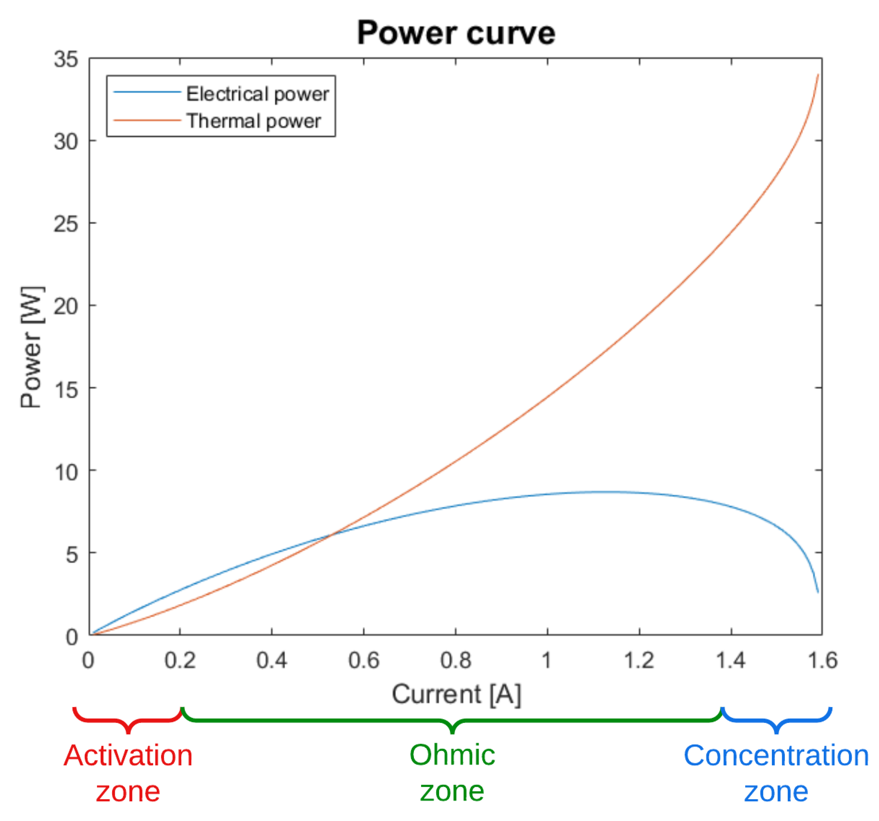
- Redox reactions need an activation energy to start, especially important in low-current scenarios.
- Ion transport across the membrane and electrodes involve ohmic resistance, neglected in the case of bipolar plates.
- There is a drop in voltage due to matter transport through porous electrodes, specifically the gas diffusion layer. This phenomenon is especially harsh at high currents and is related to current density j, which is a function of current I and the electrode area A:
- is the Nernst reversible potential;
- and is the voltage drop provoked by activation at the anodic and cathodic electrodes, respectively;
- is the voltage caused by ohmic resistance;
- and are the voltage drop due to matter transport at the anodic and cathodic electrode, respectively, also known as concentration losses.
- Generation of liquid water in LT-PEMFCs causes problems when managing this water and its distribution along the system. In LT-PEMFCs, membrane humidity should be kept within limits for proper operation. This humidity should not be too low, as a dry membrane does not work properly, but neither should it be too high, as this can lead to membrane flooding. This is not a problem in the case of HT-PEMFCs, as temperatures above water’s boiling point turns the water into vapour, and membrane operation is not as restrictive as in LT-PEMFCs [15,16].
- The electrochemical reaction at the cathode side is slowed in LT-PEMFCs. This may cause cathode overpotential, responsible for cell voltage losses [13].
- A high concentrations of carbon monoxide (CO, above 10 ppm) reduces performance, as it causes platinum poisoning (platinum being used as an electro-catalyst). Although platinum poisoning cannot be completely eliminated, this risk is substantially reduced in the case of HT-PEMFC, as higher temperatures (above 140 °C) allow higher CO tolerance. This is because higher temperatures catalyse the chemical reaction between CO and water vapour to form CO2 and hydrogen [3].
3.1. Proton Exchange Membrane Fuel Cell Models
3.2. Proton Exchange Membrane Fuel Cell Control Strategies
- Operating temperature: to prevent excess damage to the cell materials and to meet the required output heat.
- Fuel cell stack voltage or fuel cell stack current: to match the electrical demand required from the fuel cell. If voltage is fixed, current is consequently fixed, as the polarisation curve establishes a direct relation between them. Similarly, if current is chosen as the control variable, voltage follows its behaviour. Choosing current instead of voltage has the advantage of establishing a direct link with hydrogen flow, as they are directly related, while voltage control is done from an electrical point of view through voltage converters.
- Input gases: the amount of each gas injected, as well as their pressure and humidity, influence the stoichiometry and initial reaction conditions. These flows can be controlled to match a particular reactant balance.
3.3. Proton Exchange Membrane Fuel Cell Degradation
- Chemical and mechanical membrane degradation: damage to the membrane affecting the subsequent proton exchange [52].
- Starvation: when the stoichiometry of the reactants (hydrogen and oxygen) is insufficient for the reaction to take place.
- Thermal degradation: material degradation caused by excessive exposure to heat [13].
- Catalyst carbon corrosion: carbon structure of the catalyst is damaged [53].
- Catalytic layer separation: loss of contact between the layers, impeding a proper chemical reaction [54].
- Platinum agglomeration and dissolution: loss of active area of platinum in the catalyst, thus reducing its effect [53].
- Catalyst poisoning: loss of effectiveness of the catalyst due to excessive contact with carbon monoxide (CO) [13].
- Hydrophobic losses in the gas diffusion layer (GDL): transport problems of gases through the porous environment [53].
- Semi-empirical degradation model: based on theoretical regression models to be fitted with parameters experimentally. Experimental data are used to find simple correlations, which is much more direct than the ones codified by physical degradation models. These correlations can be used to directly act against degradation by modifying easily accessible variables, which is not easy for internal variables involved in degradation mechanisms [82,83].
4. Micro CHP Applications
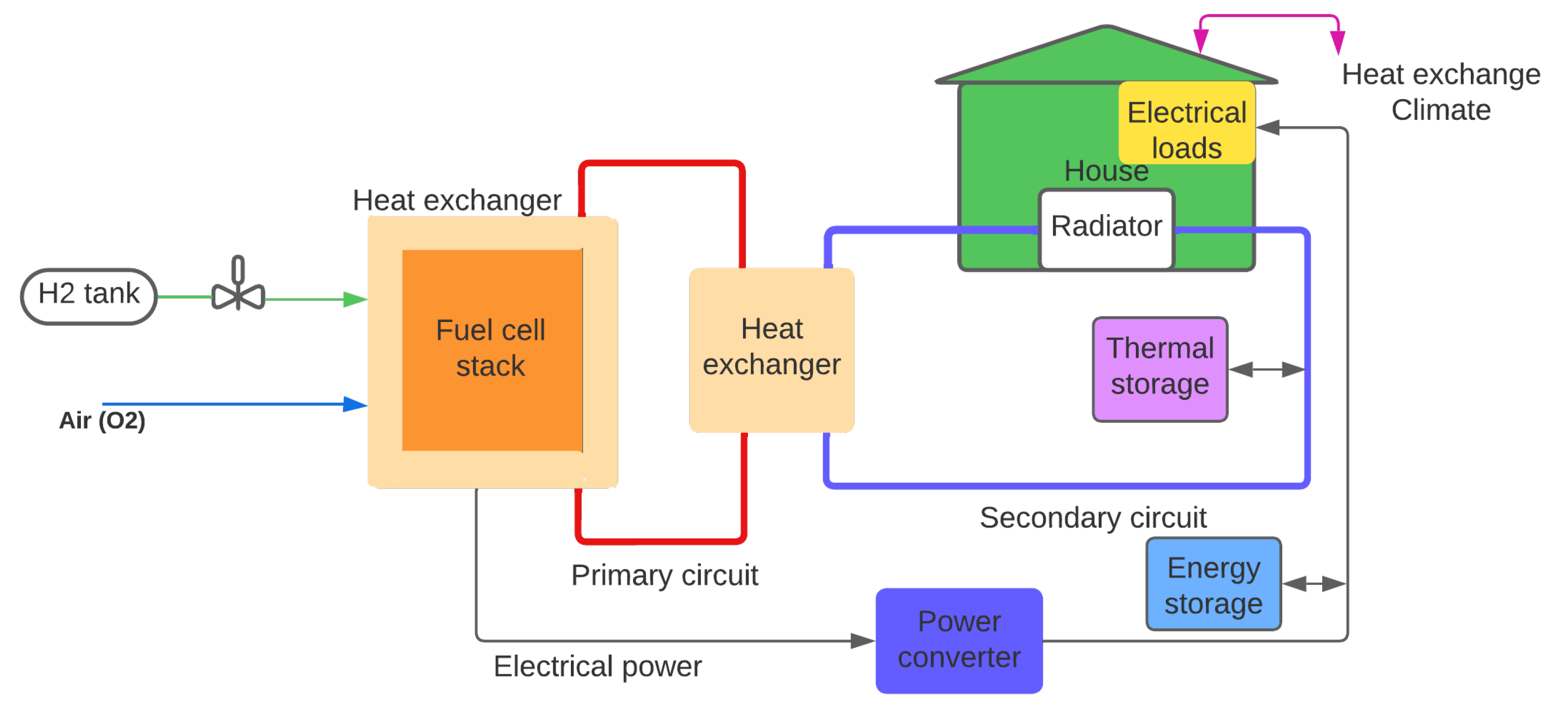
- Fuel cell stack: an array of fuel cells dimensioned depending on the power required, with characteristics described above.
- Heat exchanger: HT-PEMFC heat needs to be processed with a cooling system in many applications, but is used in the case of CHP systems. For this reason, a heat exchanger is required to convey and adapt the temperature of an external fluid that acts as a medium to transfer this heat to use it for thermal demands, although some applications use equivalent systems based on air exchange [86].
- Power conditioning system: converts DC current generated by the fuel cell stack into the adequate shape, be it DC or AC (specifying its voltage levels). Different converters need to be designed for different parts of the system.
- Battery systems: used to save electrical energy during periods of low use for future demand. Storage of this extra energy mitigates problems caused by sudden demand in future periods, preventing overwork in the fuel cell that could contribute to fast degradation.
- Water storage tanks: has an equivalent role to the one corresponding to battery systems, but with the goal of storing hot water to be used later for thermal demands. Due to the fact that fuel cells generate both electrical and thermal energy simultaneously, it is quite typical that high electrical demands produce extra heat that can be stored. The opposite case is also possible, when high thermal demand is needed despite low electrical demand.
- Fuel cell stack with insulation;
- Heat exchanger;
- Desulphuriser;
- Controls and inverter.
5. Energy Management Control Algorithms for Housing Facilities
- Local controllers: control devices such as the fuel cell stack, thermal storage and electrical battery systems. Ensures stability and proper operation of each device.
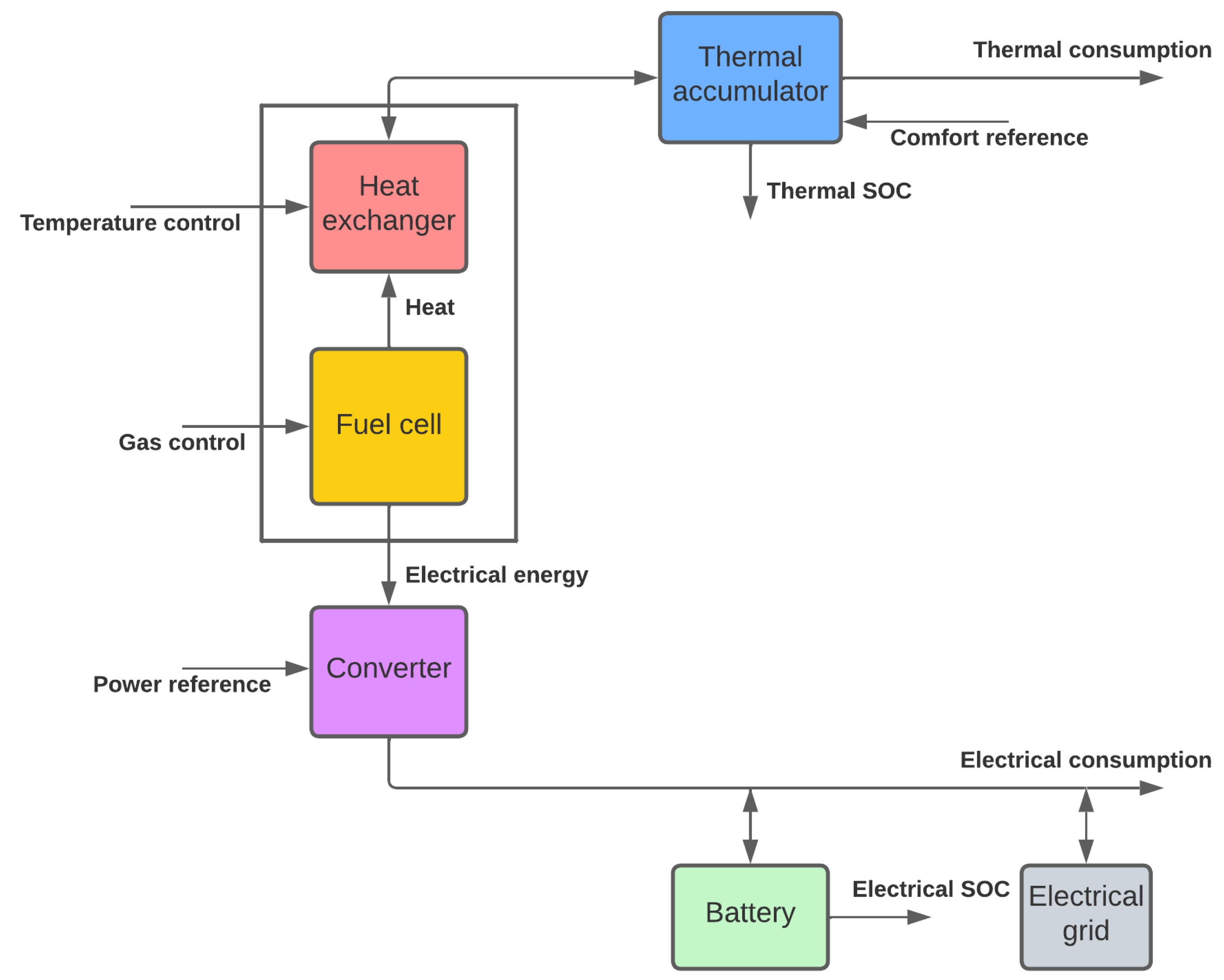
- Supervisory control: computes and provides system variable values so that electrical and thermal demand at all times are fulfilled. Among all devices involved in the CHP system, some need to be prioritised depending on certain defined objectives. These can be related to efficiency, environmental reasons, mitigating degradation, etc. Figure 6 shows systems controlled and variables provided by the supervisory control: fuel cell, water storage elements and battery systems, as previously presented in Figure 5. Additionally, external elements such as electrical grid connections, thermal energy generated via electrical devices and thermal energy released as waste are depicted. The variables that govern these elements are those that activate or disable them.
- CHP housing systems and their mathematical models;
- Algorithms for CHP energy management.
- Fuel cell current: this must be the main electrical source, instead of grid or other traditional sources, to satisfy demand. However, its variation should also be smooth to prevent degradation, as start–stop reduces fuel cell lifespan. As a consequence, two objectives arise: maximise fuel cell current while reducing current variation.
- Battery state of charge (SOC): batteries must be used to store excess electrical energy during periods of low demand. However, the battery’s state of charge must be kept between limits to avoid degradation.
- Water tank temperature: thermal energy must be used to heat the water tank, so that hot water can be used later to match thermal demand. This value should be below water’s boiling temperature and should be quite stable to be ready when needed.
- Security connections: connection to the grid must be used only when needed, avoiding fast switching between fuel cell, battery and grid. Only in extreme cases and for concretely isolated iterations should this connection be enabled. The same should happen for security connection enablement, such as generating thermal energy via an electric space heater or releasing extra heat produced by the fuel cell to the environment. Both cases should be limited to exceptional occasions.
- Rule-based models;
- Recursive methods;
- Model predictive control (MPC).
5.1. Rule-Based Models
5.2. Recursive Methods
5.3. Model Predictive Control
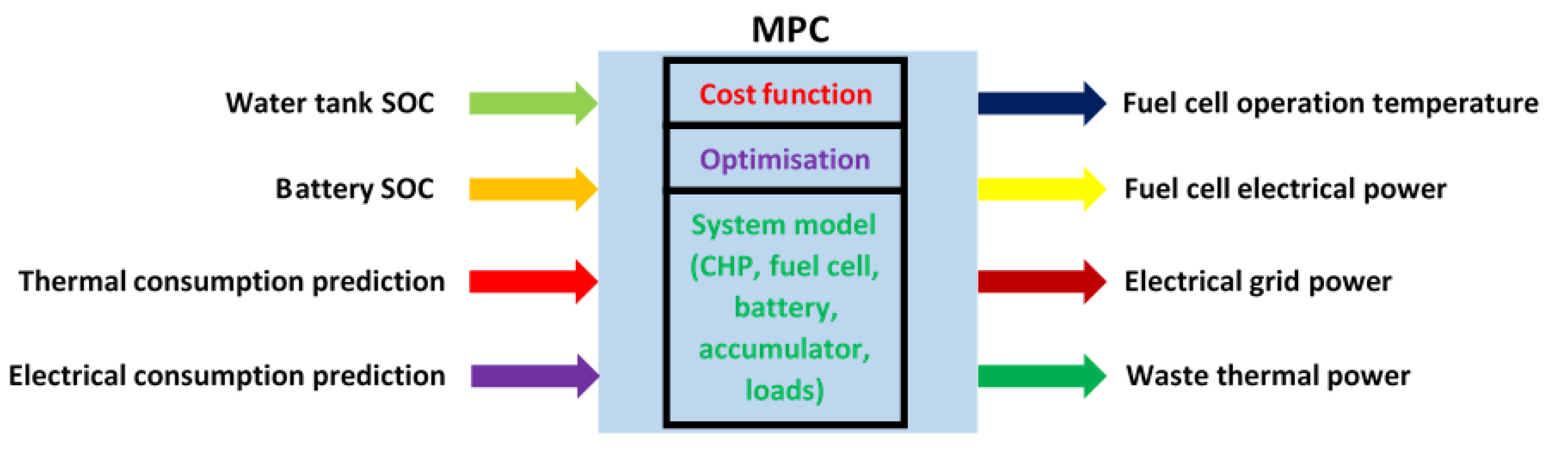
- Objective function: formed by a set of subfunctions to be minimised, such as fuel cell current and its variation, battery and water tank fluctuations, and energy exchanged with the grid or the environment. These subfunctions need to be multiplied by weight functions so that they can be added and form the global objective function to be minimised. These weight functions need to be selected so that some objectives are prioritised above others.
- Variables: system variables include fuel cell current and variables governing activation and deactivation of the battery, water accumulator, grid connection and environment connection. Electrical and thermal demands are included as system disturbances. Disturbance variables must be predicted so that the MPC can compute future scenarios, even though they cannot be predicted exactly (Figure 9).
- Constraints: these include upper and lower bounds for electrical current, battery state of charge, water accumulator temperature and others. Additionally, the system equations need to be imposed as a constraint.
- Prediction horizon: optimisation is based on the system model and variables evaluated at the current time-step iteration, but it also anticipates future evolution of these variables. For this reason, a certain number of iterations in advance are predicted so that disturbances and other variables are simulated, preparing the system trajectory for what is to come (Figure 9). The control horizon () and prediction horizon () move every time the iteration k advances, predicting an extra step while computing real values for the ones already completed. This ensures reliability and robustness when trying to fulfil electrical and thermal demands.
Multiobjective Problem Analysis Using Pareto Fronts
- A set of clusters of points is defined successively based on the solutions of the optimisation problem;
- For each specific configuration, values are assigned to each cluster;
- The average of every cluster is obtained, and a curve representative of the cluster is defined;
- For each configuration, the centroid profile is calculated;
- This profile’s values are sorted, creating sorted means and classifying them by the order in which they appear in the original curve;
- Values are sorted according to the order established by the cluster’s representative curve.
6. Conclusions
Author Contributions
Funding
Institutional Review Board Statement
Informed Consent Statement
Data Availability Statement
Conflicts of Interest
Abbreviations
| HT | High-temperature |
| LT | Low-temperature |
| PEM | Proton exchange membrane |
| FC | Fuel cell |
| PEMFC | Proton exchange membrane fuel cell |
| HT-PEMFC | High-temperature proton exchange membrane fuel cell |
| LT-PEMFC | Low-temperature proton exchange membrane fuel cell |
| DMFC | Direct methanol fuel cell |
| AFC | Alkaline fuel cell |
| PAFC | Phosphoric acid fuel cell |
| MCFC | Molten carbonate fuel cell |
| SOFC | Solid oxide fuel cell |
| CHP | Combined heat and power |
| ECSA | Electrochemical active surface area |
| SOC | State of charge of a battery or other storage element |
| MPC | Model predictive control |
References
- Pew Climate Center. Cogeneration/Combined Heat and Power: An Overview. Cogener. Distrib. Gener. J. 2009, 17, 64–79. [Google Scholar] [CrossRef]
- Gao, S.; Jurasz, J.; Li, H.; Corsetti, E.; Yan, J. Potential benefits from participating in day-ahead and regulation markets for CHPs. Appl. Energy 2022, 306, 117974. [Google Scholar] [CrossRef]
- Ellamla, H.R.; Staffell, I.; Bujlo, P.; Pollet, B.G.; Pasupathi, S. Current status of fuel cell based combined heat and power systems for residential sector. J. Power Sources 2015, 293, 312–328. [Google Scholar] [CrossRef]
- Elmer, T.; Worall, M.; Wu, S.; Riffat, S.B. Fuel cell technology for domestic built environment applications: State of-the-art review. Renew. Sustain. Energy Rev. 2015, 42, 913–931. [Google Scholar] [CrossRef]
- Hikima, K.; Tsujimoto, M.; Takeuchi, M.; Kajikawa, Y. Transition analysis of budgetary allocation for projects on hydrogen-related technologies in Japan. Sustainability 2020, 12, 8546. [Google Scholar] [CrossRef]
- Jo, A.; Oh, K.; Lee, J.; Han, D.; Kim, D.; Kim, J.; Kim, B.; Kim, J.; Park, D.; Kim, M.; et al. Modeling and analysis of a 5 kWe HT-PEMFC system for residential heat and power generation. Int. J. Hydrogen Energy 2016, 42, 1698–1714. [Google Scholar] [CrossRef]
- Lambert, H.; Roche, R.; Jemeï, S.; Ortega, P.; Hissel, D. Combined Cooling and Power Management Strategy for a Standalone House Using Hydrogen and Solar Energy. Hydrogen 2021, 2, 207–224. [Google Scholar] [CrossRef]
- Peláez-Peláez, S.; Colmenar-Santos, A.; Pérez-Molina, C.; Rosales, A.E.; Rosales-Asensio, E. Techno-economic analysis of a heat and power combination system based on hybrid photovoltaic-fuel cell systems using hydrogen as an energy vector. Energy 2021, 224, 120110. [Google Scholar] [CrossRef]
- Arsalis, A.; Nielsen, M.P.; Kaer, S.K. Modeling and off-design performance of a 1kWe HT-PEMFC (high temperature-proton exchange membrane fuel cell)-based residential micro-CHP (combined-heat-and-power) system for Danish single-family households. Energy 2011, 36, 993–1002. [Google Scholar] [CrossRef]
- Lavernia, A.; Dover, T.; Samuelsen, S. Operational and economic performance analysis of a high-temperature fuel cell cogeneration plant. J. Power Sources 2022, 520, 230798. [Google Scholar] [CrossRef]
- Najafi, B.; Haghighat Mamaghani, A.; Rinaldi, F.; Casalegno, A. Long-term performance analysis of an HT-PEM fuel cell based micro-CHP system: Operational strategies. Appl. Energy 2015, 147, 582–592. [Google Scholar] [CrossRef]
- Larsen, G.K.; Van Foreest, N.D.; Scherpen, J.M. Distributed MPC applied to a network of households with Micro-CHP and heat storage. IEEE Trans. Smart Grid 2014, 5, 2106–2114. [Google Scholar] [CrossRef]
- Hissel, D.; Péra, M. Diagnostic & health management of fuel cell systems: Issues and solutions. Annu. Rev. Control. 2016, 42, 201–211. [Google Scholar] [CrossRef]
- Ramousse, J.; Lottin, O.; Didierjean, S.; Maillet, D. Heat sources in proton exchange membrane (PEM) fuel cells. J. Power Sources 2009, 192, 435–441. [Google Scholar] [CrossRef]
- Liu, Y.; Lehnert, W.; Janßen, H.; Samsun, R.C.; Stolten, D. A review of high-temperature polymer electrolyte membrane fuel-cell (HT-PEMFC)-based auxiliary power units for diesel-powered road vehicles. J. Power Sources 2016, 311, 91–102. [Google Scholar] [CrossRef]
- Abdul Rasheed, R.K.; Liao, Q.; Caizhi, Z.; Chan, S.H. A review on modelling of high temperature proton exchange membrane fuel cells (HT-PEMFCs). Int. J. Hydrogen Energy 2017, 42, 3142–3165. [Google Scholar] [CrossRef]
- Abdul Rasheed, R.K.; Chan, S.H. Transient carbon monoxide poisoning kinetics during warm-up period of a high-temperature PEMFC - Physical model and parametric study. Appl. Energy 2015, 140, 44–51. [Google Scholar] [CrossRef]
- Bednarek, T.; Tsotridis, G. Issues associated with modelling of proton exchange membrane fuel cell by computational fluid dynamics. J. Power Sources 2017, 343, 550–563. [Google Scholar] [CrossRef]
- Ju, H.; Meng, H.; Wang, C.Y. A single-phase, non-isothermal model for PEM fuel cells. Int. J. Heat Mass Transf. 2005, 48, 1303–1315. [Google Scholar] [CrossRef]
- Shan, Y.; Choe, S.Y. A high dynamic PEM fuel cell model with temperature effects. J. Power Sources 2005, 145, 30–39. [Google Scholar] [CrossRef]
- Leonard Efrén Dueñas Gutíerrez. Simulación Numérica 3D No-Isoterma de una Pila de Combustible de Membrana Polimérica de alta Temperatura. Ph.D. Thesis, Laboratorio de Investigación en Fluidodinámica y Tecnologías de la Combustión (LIFTEC-CSIC/UZ), Zaragoza, Spain, 2015. [CrossRef]
- Bergmann, A.; Gerteisen, D.; Kurz, T. Modelling of CO poisoning and its dynamics in HTPEM fuel cells. Fuel Cells 2010, 10, 278–287. [Google Scholar] [CrossRef]
- Ferng, Y.M.; Su, A.; Hou, J. Parametric investigation to enhance the performance of a PBI-based high-temperature PEMFC. Energy Convers. Manag. 2014, 78, 431–437. [Google Scholar] [CrossRef]
- Belyaev, P.V.; Technical, O.S.; Mischenko, V.S.; Technical, O.S.; Podberezkin, D.A.; Technical, O.S.; Technical, O.S. Simulation modeling of proton exchange membrane fuel cells. In Proceedings of the 2016 Dynamics of Systems, Mechanisms and Machines (Dynamics), Omsk, Russia, 15–17 November 2016; Volume 1, pp. 1–5. [Google Scholar]
- Sohn, Y.J.; Yim, S.D.; Park, G.G.; Kim, M.; Cha, S.W.; Kim, K. PEMFC modeling based on characterization of effective diffusivity in simulated cathode catalyst layer. Int. J. Hydrogen Energy 2017, 42, 13226–13233. [Google Scholar] [CrossRef]
- Mangold, M.; Bück, A.; Hanke-Rauschenbach, R. Passivity based control of a distributed PEM fuel cell model. J. Process. Control. 2010, 20, 292–313. [Google Scholar] [CrossRef]
- Rosli, R.E.; Sulong, A.B.; Daud, W.R.; Zulkifley, M.A.; Husaini, T.; Rosli, M.I.; Majlan, E.H.; Haque, M.A. A review of high-temperature proton exchange membrane fuel cell (HT-PEMFC) system. Int. J. Hydrogen Energy 2017, 42, 9293–9314. [Google Scholar] [CrossRef]
- Zhang, C.; Yu, T.; Yi, J.; Liu, Z.; Raj, K.A.R.; Xia, L.; Tu, Z.; Chan, S.H. Investigation of heating and cooling in a stand-alone high temperature PEM fuel cell system. Energy Convers. Manag. 2016, 129, 36–42. [Google Scholar] [CrossRef]
- Piela, P.; Mitzel, J. Polymer electrolyte membrane fuel cell efficiency at the stack level. J. Power Sources 2015, 292, 95–103. [Google Scholar] [CrossRef]
- Jia, F.; Guo, L.; Liu, H. Mitigation strategies for hydrogen starvation under dynamic loading in proton exchange membrane fuel cells. Energy Convers. Manag. 2017, 139, 175–181. [Google Scholar] [CrossRef]
- Barreras, F.; Lozano, A.; Roda, V.; Barroso, J.; Martín, J. Optimal design and operational tests of a high-temperature PEM fuel cell for a combined heat and power unit. Int. J. Hydrogen Energy 2014, 39, 5388–5398. [Google Scholar] [CrossRef] [Green Version]
- Mashio, T.; Iden, H.; Ohma, A.; Tokumasu, T. Modeling of local gas transport in catalyst layers of PEM fuel cells. J. Electroanal. Chem. 2017, 790, 27–39. [Google Scholar] [CrossRef]
- Roda, V.; Puleston, P.F. Thermal Dynamic modelling for a high-temperature PEM fuel cell. In Proceedings of theIV Symposium on Hydrogen, Fuel Cells and Advanced Batteries, HYCELTEC 2013, Estoril, Portugal, 26–28 June 2013; Volume 2, p. 911767. [Google Scholar]
- Authayanun, S.; Mamlouk, M.; Scott, K.; Arpornwichanop, A. Comparison of high-temperature and low-temperature polymer electrolyte membrane fuel cell systems with glycerol reforming process for stationary applications. Appl. Energy 2013, 109, 192–201. [Google Scholar] [CrossRef]
- Siegel, J.B. Experiments and Modeling of PEM Fuel Cells for Dead-Ended Anode Operation. Ph.D. Thesis, University of Michigan, Ann Arbor, MI, USA, 2010; pp. 1–77. [Google Scholar]
- Sherif Imam, A.A. Sizing and Economic Analysis of Standalone PEM Fuel Cell Systems for Residential Utilization. Int. Rev. Appl. Sci. Eng. 2015, 2, 1–10. [Google Scholar] [CrossRef]
- Jaggi, V.; Jayanti, S. A conceptual model of a high-efficiency, stand-alone power unit based on a fuel cell stack with an integrated auto-thermal ethanol reformer. Appl. Energy 2013, 110, 295–303. [Google Scholar] [CrossRef]
- Notter, D.A.; Kouravelou, K.; Karachalios, T.; Daletou, M.K.; Haberland, N.T. Life cycle assessment of PEM FC applications: Electric mobility and μ-CHP. Energy Environ. Sci. 2015, 8, 1969–1985. [Google Scholar] [CrossRef]
- Hawkes, A.; Staffell, I.; Brett, D.; Brandon, N. Fuel cells for micro-combined heat and power generation. Energy Environ. Sci. 2009, 2, 729. [Google Scholar] [CrossRef]
- Chang, H.; Wan, Z.; Zheng, Y.; Chen, X.; Shu, S.; Tu, Z.; Chan, S.H.; Chen, R.; Wang, X. Energy- and exergy-based working fluid selection and performance analysis of a high-temperature PEMFC-based micro combined cooling heating and power system. Appl. Energy 2017, 204, 446–458. [Google Scholar] [CrossRef]
- Romero, R.J.; Barquera, S.A.S.; Martínez, A.R.; Sotelo, S.S.; Chavez, M.A.C.; Pensado, M.A.B.; García, J.C.; Rodríguez, J.A. Waste Heat Revalorization with Electric Generation Based on Fuel Cell. Am. J. Environ. Eng. 2014, 4, 11–18. [Google Scholar] [CrossRef]
- De Lira, S.; Puig, V.; Quevedo, J.; Husar, A. LPV observer design for PEM fuel cell system: Application to fault detection. J. Power Sources 2011, 196, 4298–4305. [Google Scholar] [CrossRef]
- Bianchi, F.D.; Kunusch, C.; Ocampo-Martinez, C.; Member, S.; Sánchez-Peña, R.S.; Member, S. A Gain-Scheduled LPV Control for Oxygen Stoichiometry Regulation in PEM Fuel Cell Systems. IEEE Trans. Control. Syst. Technol. 2014, 22, 1837–1844. [Google Scholar] [CrossRef] [Green Version]
- Schultze, M.; Hähnel, C.; Horn, J. Nonlinear Model Predictive Control of a PEM Fuel Cell System for Cathode Exhaust Gas Generation. IFAC Proc. Vol. 2014, 47, 9432–9437. [Google Scholar] [CrossRef]
- Luna Pacho, J.; Usai, E.; Husar, A.; Serra Prat, M. Enhancing the Efficiency and Lifetime of a Proton Exchange Membrane Fuel Cell using Nonlinear Model Predictive Control with Nonlinear Observation. IEEE Trans. Ind. Electron. 2017, 64, 6649–6659. [Google Scholar] [CrossRef]
- Beirami, H.; Shabestari, A.Z.; Zerafat, M.M. Optimal PID plus fuzzy controller design for a PEM fuel cell air feed system using the self-adaptive differential evolution algorithm. Int. J. Hydrogen Energy 2015, 40, 9422–9434. [Google Scholar] [CrossRef]
- Torreglosa, J.; Garcia, P.; Fernandez, L.; Jurado, F. Predictive Control for the Energy Management of a Fuel Cell-Battery-Supercapacitor Tramway. IEEE Trans. Ind. Inform. 2013, 10, 276–285. [Google Scholar] [CrossRef]
- Li, Z.; Outbib, R.; Hissel, D.; Giurgea, S. Control Engineering Practice Data-driven diagnosis of PEM fuel cell: A comparative study. Control. Eng. Pract. 2014, 28, 1–12. [Google Scholar] [CrossRef]
- Das, V.; Padmanaban, S.; Venkitusamy, K.; Selvamuthukumaran, R.; Blaabjerg, F.; Siano, P. Recent advances and challenges of fuel cell based power system architectures and control—A review. Renew. Sustain. Energy Rev. 2017, 73, 10–18. [Google Scholar] [CrossRef]
- Li, D.; Yu, Y.; Jin, Q.; Gao, Z. Maximum power efficiency operation and generalized predictive control of PEM (proton exchange membrane) fuel cell. Energy 2014, 68, 210–217. [Google Scholar] [CrossRef]
- Abbaspour, A.; Khalilnejad, A.; Chen, Z. Robust adaptive neural network control for PEM fuel cell. Int. J. Hydrogen Energy 2016, 41, 20385–20395. [Google Scholar] [CrossRef]
- Dubau, L.; Castanheira, L.; Maillard, F.; Chatenet, M.; Lottin, O.; Maranzana, G.; Dillet, J.; Lamibrac, A.; Perrin, J.C.; Moukheiber, E.; et al. A review of PEM fuel cell durability: Materials degradation, local heterogeneities of aging and possible mitigation strategies. Wiley Interdiscip. Rev. Energy Environ. 2014, 3, 540–560. [Google Scholar] [CrossRef]
- Kim, J.; Kim, M.; Lee, B.G.; Sohn, Y.J. Durability of high temperature polymer electrolyte membrane fuel cells in daily based start/stop operation mode using reformed gas. Int. J. Hydrogen Energy 2015, 40, 7769–7776. [Google Scholar] [CrossRef]
- Shao, Y.; Yin, G.; Gao, Y. Understanding and approaches for the durability issues of Pt-based catalysts for PEM fuel cell. J. Power Sources 2007, 171, 558–566. [Google Scholar] [CrossRef]
- Kim, J.; Kim, M.; Kang, T.; Sohn, Y.J.; Song, T.; Choi, K.H. Degradation modeling and operational optimization for improving thelifetime of high-temperature PEM (proton exchange membrane) fuel cells. Energy 2014, 66, 41–49. [Google Scholar] [CrossRef]
- Sondergaard, S.; Cleemann, L.; Jensen, J.; Bjerrum, N. Influence of carbon monoxide on the cathode in high-temperature polymer electrolyte membrane fuel cells. Int. J. Hydrogen Energy 2017, 42, 3309–3315. [Google Scholar] [CrossRef]
- Stevens, D.A.; Dahn, J.R. Thermal degradation of the support in carbon-supported platinum electrocatalysts for PEM fuel cells. Carbon 2005, 43, 179–188. [Google Scholar] [CrossRef]
- Araya, S.S.; Grigoras, I.F.; Zhou, F.; Andreasen, S.J.; Kaer, S.K. Performance and endurance of a high temperature PEM fuel cell operated on methanol reformate. Int. J. Hydrogen Energy 2014, 39, 18343–18350. [Google Scholar] [CrossRef]
- Lechartier, E.; Gou, R.; Péra, M.C.; Hissel, D. Static and dynamic modeling of a PEMFC for prognostics purpose. In Proceedings of the 2014 IEEE Vehicle Power and Propulsion Conference (VPPC), Coimbra, Portugal, 27–30 October 2014; pp. 1–5. [Google Scholar]
- Chandesris, M.; Vincent, R.; Guetaz, L.; Roch, J.S.; Thoby, D.; Quinaud, M. Membrane degradation in PEM fuel cells: From experimental results to semi-empirical degradation laws. Int. J. Hydrogen Energy 2017, 42, 8139–8149. [Google Scholar] [CrossRef]
- Jomori, S.; Nonoyama, N.; Yoshida, T. Analysis and modeling of PEMFC degradation: Effect on oxygen transport. J. Power Sources 2012, 215, 18–27. [Google Scholar] [CrossRef]
- Jouin, M.; Gouriveau, R.; Hissel, D.; Péra, M.C.; Zerhouni, N. Prognostics and Health Management of PEMFC - State of the art and remaining challenges. Int. J. Hydrogen Energy 2013, 38, 15307–15317. [Google Scholar] [CrossRef]
- Chattot, R.; Escribano, S. Ageing studies of a PEM Fuel Cell stack developed for reformate fuel operation in μCHP units: Development of an accelerated degradation procedure. Int. J. Hydrogen Energy 2014, 40, 5367–5374. [Google Scholar] [CrossRef]
- De Bruijn, F.A.; Dam, V.A.T.; Janssen, G.J.M. Review: Durability and degradation issues of PEM fuel cell components. Fuel Cells 2008, 8, 3–22. [Google Scholar] [CrossRef]
- Endoh, E.; Terazono, S.; Widjaja, H.; Takimoto, Y. Degradation Study of MEA for PEMFCs under Low Humidity Conditions. Electrochem.-Solid-State Lett. 2004, 7, A209–A211. [Google Scholar] [CrossRef]
- Jahnke, T.; Futter, G.; Latz, A.; Malkow, T.; Papakonstantinou, G.; Tsotridis, G.; Schott, P.; Gérard, M.; Quinaud, M.; Quiroga, M.; et al. Performance and degradation of Proton Exchange Membrane Fuel Cells: State of the art in modeling from atomistic to system scale. J. Power Sources 2016, 304, 207–233. [Google Scholar] [CrossRef]
- Kulikovsky, A.A. The effect of stoichiometric ratio on the performance of a polymer electrolyte fuel cell. Electrochim. Acta 2014, 49, 617–625. [Google Scholar] [CrossRef]
- Robin, C.; Gerard, M.; Franco, A.A.; Schott, P. Multi-scale coupling between two dynamical models for PEMFC aging prediction. Int. J. Hydrogen Energy 2013, 38, 4675–4688. [Google Scholar] [CrossRef]
- Schmittinger, W.; Vahidi, A. A review of the main parameters influencing long-term performance and durability of PEM fuel cells. J. Power Sources 2008, 180, 1–14. [Google Scholar] [CrossRef]
- Cai, M.; Ruthkosky, M.S.; Merzougui, B.; Swathirajan, S.; Balogh, M.P.; Oh, S.H. Investigation of thermal and electrochemical degradation of fuel cell catalysts. J. Power Sources 2006, 160, 977–986. [Google Scholar] [CrossRef]
- Malek, K.; Franco, A.A. Microstructure-based modeling of aging mechanisms in catalyst layers of polymer electrolyte fuel cells. J. Phys. Chem. B 2011, 115, 8088–8101. [Google Scholar] [CrossRef]
- Petrone, R.; Hissel, D.; Péra, M.C.; Chamagne, D.; Gouriveau, R. Accelerated stress test procedures for PEM fuel cells under actual load constraints: State-of-art and proposals. Int. J. Hydrogen Energy 2015, 40, 12489–12505. [Google Scholar] [CrossRef]
- Yousfi-Steiner, N.; Moçotéguy, P.; Candusso, D.; Hissel, D. A review on polymer electrolyte membrane fuel cell catalyst degradation and starvation issues: Causes, consequences and diagnostic for mitigation. J. Power Sources 2009, 194, 130–145. [Google Scholar] [CrossRef]
- Kätzel, J.; Markötter, H.; Arlt, T.; Klages, M.; Haußmann, J.; Messerschmidt, M.; Kardjilov, N.; Scholta, J.; Banhart, J.; Manke, I. Effect of ageing of gas diffusion layers on the water distribution in flow field channels of polymer electrolyte membrane fuel cells. J. Power Sources 2016, 301, 386–391. [Google Scholar] [CrossRef]
- Xing, Y.; Bernadet, L.; Torrell, M.; Tarancón, A.; Costa-Castelló, R.; Na, J. Offline and online parameter estimation of nonlinear systems: Application to a solid oxide fuel cell system. ISA Trans. 2022, in press. [Google Scholar] [CrossRef]
- Xing, Y.; Na, J.; Chen, M.; Costa-Castelló, R.; Roda, V. Adaptive Nonlinear Parameter Estimation for a Proton Exchange Membrane Fuel Cell. IEEE Trans. Power Electron. 2022, 37, 9012–9023. [Google Scholar] [CrossRef]
- Cecilia, A.; Serra, M.; Costa-Castelló, R. Nonlinear adaptive observation of the liquid water saturation in polymer electrolyte membrane fuel cells. J. Power Sources 2021, 492, 229641. [Google Scholar] [CrossRef]
- Luna, J.; Costa-Castelló, R.; Strahl, S. Chattering free sliding mode observer estimation of liquid water fraction in proton exchange membrane fuel cells. J. Frankl. Inst. 2020, 357, 13816–13833. [Google Scholar] [CrossRef]
- Cecilia, A.; Costa-Castelló, R. Observador de alta ganancia con zona muerta ajustable para estimar la saturación de agua líquida en pilas de combustible tipo PEM. Rev. Iberoam. Autom. Inform. Ind. 2020, 17, 169–180. [Google Scholar] [CrossRef]
- Jin, X.; Vora, A.P.; Hoshing, V.; Saha, T.; Shaver, G.M.; Wasynczuk, O.; Varigonda, S. Comparison of Li-ion battery degradation models for system design and control algorithm development. In Proceedings of the 2017 American Control Conference (ACC), Seattle, WA, USA, 24–26 May 2017; Volume 4, pp. 74–79. [Google Scholar] [CrossRef]
- Lechartier, E.; Laffly, E.; Péra, M.C.; Gouriveau, R.; Hissel, D.; Zerhouni, N. Proton exchange membrane fuel cell behavioral model suitable for prognostics. Int. J. Hydrogen Energy 2015, 40, 8384–8397. [Google Scholar] [CrossRef]
- Jouin, M.; Gouriveau, R.; Hissel, D.; Péra, M.C.; Zerhouni, N. Degradations analysis and aging modeling for health assessment and prognostics of PEMFC. Reliab. Eng. Syst. Saf. 2016, 148, 78–95. [Google Scholar] [CrossRef]
- Jouin, M.; Bressel, M.; Morando, S.; Gouriveau, R.; Hissel, D.; Péra, M.C.; Zerhouni, N.; Jemei, S.; Hilairet, M.; Ould Bouamama, B. Estimating the end-of-life of PEM fuel cells: Guidelines and metrics. Appl. Energy 2016, 177, 87–97. [Google Scholar] [CrossRef]
- Carignano, M.G.; Costa-Castelló, R.; Roda, V.; Nigro, N.M.; Junco, S.; Feroldi, D. Energy management strategy for fuel cell-supercapacitor hybrid vehicles based on prediction of energy demand. J. Power Sources 2017, 360, 419–433. [Google Scholar] [CrossRef] [Green Version]
- Navarro Gimenez, S.; Herrero Dura, J.M.; Blasco Ferragud, F.X.; Simarro Fernandez, R. Control-Oriented Modeling of the Cooling Process of a PEMFC-Based μ-CHP System. IEEE Access 2019, 7, 95620–95642. [Google Scholar] [CrossRef]
- De las Heras, A.; Vivas, F.J.; Segura, F.; Redondo, M.J.; Andújar, J.M. Air-cooled fuel cells: Keys to design and build the oxidant/cooling system. Renew. Energy 2018, 125, 1–20. [Google Scholar] [CrossRef]
- PACE Project. Available online: https://https://pace-energy.eu/ (accessed on 20 July 2022).
- Das, S.K.; Gibson, H.A. Three dimensional multi-physics modeling and simulation for assessment of mass transport impact on the performance of a high temperature polymer electrolyte membrane fuel cell. J. Power Sources 2021, 499, 229844. [Google Scholar] [CrossRef]
- Aljabery, A.A.M.; Mehrjerdi, H.; Mahdavi, S.; Hemmati, R. Multi carrier energy systems and energy hubs: Comprehensive review, survey and recommendations. Int. J. Hydrogen Energy 2021, 46, 23795–23814. [Google Scholar] [CrossRef]
- Salgado, M.; Negrete-Pincetic, M.; Lorca, Á.; Olivares, D. A low-complexity decision model for home energy management systems. Appl. Energy 2021, 294, 116985. [Google Scholar] [CrossRef]
- Gros, S.; Jakus, D.; Vasilj, J.; Zanon, M. Day-ahead scheduling and real-time economic MPC of CHP unit in microgrid with smart buildings. IEEE Trans. Smart Grid 2019, 10, 1992–2001. [Google Scholar] [CrossRef]
- Haase, P.; Thomas, B. Test and optimization of a control algorithm for demand-oriented operation of CHP units using hardware-in-the-loop. Appl. Energy 2021, 294, 116974. [Google Scholar] [CrossRef]
- Cheng, Z.; Geng, G.; Jiang, Q.; Guerrero, J.M. Energy Management of CHP-Based Microgrid with Thermal Storage for Reducing Wind Curtailment. J. Energy Eng. 2018, 144, 04018066. [Google Scholar] [CrossRef]
- Yang, T.; Zhao, L.; Li, W.; Wu, J.; Zomaya, A.Y. Towards healthy and cost-effective indoor environment management in smart homes: A deep reinforcement learning approach. Appl. Energy 2021, 300, 117335. [Google Scholar] [CrossRef]
- Cecilia, A.; Carroquino, J.; Roda, V.; Costa-Castelló, R.; Barreras, F. Optimal Energy Management in a Standalone Microgrid, with Photovoltaic Generation, Short-Term Storage, and Hydrogen Production. Energies 2020, 13, 1454. [Google Scholar] [CrossRef] [Green Version]
- Nair, U.R.; Costa-Castelló, R. A Model Predictive Control-Based Energy Management Scheme for Hybrid Storage System in Islanded Microgrids. IEEE Access 2020, 8, 97809–97822. [Google Scholar] [CrossRef]
- Nair, U.R.; Sandelic, M.; Sangwongwanich, A.; Dragicevic, T.; Costa-Castelló, R.; Blaabjerg, F. Grid congestion mitigation and battery degradation minimisation using model predictive control in PV-based microgrid. IEEE Trans. Energy Convers. 2021, 36, 1500–1509. [Google Scholar] [CrossRef]
- Garrido Satué, M.; Ruiz Arahal, M.; Rodríguez Ramírez, D. Estimación de intensidades rotóricas en máquinas polifásicas para control predictivo. Rev. Iberoam. Autom. Inform. Ind. 2022, in press. [Google Scholar] [CrossRef]
- Diaz, C.J.L.; Ocampo-Martinez, C.; Panten, N.; Weber, T.; Abele, E. Optimal operation of combined heat and power systems: An optimization-based control strategy. Energy Convers. Manag. 2019, 199, 111957. [Google Scholar] [CrossRef]
- Löhr, Y.; Wolf, D.; Pollerberg, C.; Hörsting, A.; Mönnigmann, M. Supervisory model predictive control for combined electrical and thermal supply with multiple sources and storages. Appl. Energy 2021, 290, 116742. [Google Scholar] [CrossRef]
- Bürger, A.; Bull, D.; Sawant, P.; Bohlayer, M.; Klotz, A.; Beschütz, D.; Altmann-Dieses, A.; Braun, M.; Diehl, M. Experimental operation of a solar-driven climate system with thermal energy storages using mixed-integer nonlinear model predictive control. Optim. Control. Appl. Methods 2021, 42, 1293–1319. [Google Scholar] [CrossRef]
- Pajares, A.; Blasco, X.; Herrero, J.M.; Simarro, R. Multivariable Controller Design for the Cooling System of a PEM Fuel Cell by considering Nearly Optimal Solutions in a Multiobjective Optimization Approach. Complexity 2020, 2020, 8649428. [Google Scholar] [CrossRef]
- Zhang, Y.; Meng, F.; Wang, R.; Kazemtabrizi, B.; Shi, J. Uncertainty-resistant stochastic MPC approach for optimal operation of CHP microgrid. Energy 2019, 179, 1265–1278. [Google Scholar] [CrossRef]
- Pascual, J.; Arcos-Aviles, D.; Ursúa, A.; Sanchis, P.; Marroyo, L. Energy management for an electro-thermal renewable–based residential microgrid with energy balance forecasting and demand side management. Appl. Energy 2021, 295, 117062. [Google Scholar] [CrossRef]
- Nair, U.R.; Sandelic, M.; Sangwongwanich, A.; Dragicevic, T.; Costa-Castelló, R.; Blaabjerg, F. An analysis of multi objective energy scheduling in PV-BESS system under prediction uncertainty. IEEE Trans. Energy Convers. 2021, 36, 2276–2286. [Google Scholar] [CrossRef]
- He, L.; Lu, Z.; Pan, L.; Zhao, H.; Li, X.; Zhang, J. Optimal economic and emission dispatch of a microgrid with a combined heat and power system. Energies 2019, 12, 604. [Google Scholar] [CrossRef]
- Hemmati, M.; Amin, M.; Abapour, M.; Zare, K. Economic-environmental analysis of combined heat and power-based reconfigurable microgrid integrated with multiple energy storage and demand response program. Sustain. Cities Soc. 2021, 69, 102790. [Google Scholar] [CrossRef]
- Li, L.; Wang, J.; Zhong, X.; Lin, J.; Wu, N.; Zhang, Z.; Meng, C.; Wang, X.; Shah, N.; Brandon, N.; et al. Combined multi-objective optimization and agent-based modeling for a 100% renewable island energy system considering power-to-gas technology and extreme weather conditions. Appl. Energy 2022, 308, 118376. [Google Scholar] [CrossRef]
- Efkarpidis, N.A.; Vomva, S.A.; Christoforidis, G.C.; Papagiannis, G.K. Optimal day-to-day scheduling of multiple energy assets in residential buildings equipped with variable-speed heat pumps. Appl. Energy 2022, 312, 118702. [Google Scholar] [CrossRef]
- Hoffmann, M.; Kotzur, L.; Stolten, D. The Pareto-Optimal Temporal Aggregation of Energy System Models. Appl. Energy 2021, 315, 119029. [Google Scholar] [CrossRef]
- Petrelli, M.; Fioriti, D.; Berizzi, A.; Bovo, C.; Poli, D. A novel multi-objective method with online Pareto pruning for multi-year optimization of rural microgrids. Appl. Energy 2021, 299, 117283. [Google Scholar] [CrossRef]


| Type | Electrolyte | Temp. (°C) | Fuel | Advantages | Problems |
|---|---|---|---|---|---|
| Polymeric (PEMFC) | Polymeric membrane | 30–100 (LT) 120–200 (HT) | H2 | - Fast start-up - Solid electrolyte | - Pure H2 needed - Expensive catalyst |
| Direct Methanol (DMFC) | Polymeric membrane | 30–100 | CH3OH | - Liquid fuel - No reforming step for fuel | - Slow reaction - Fuel crossover from anode to cathode |
| Alkaline (AFC) | KOH (liquid) | 65–220 | KOH | - Better current response (fast cathodic reaction) | - Reactants must be removed |
| Phosphoric Acid (PAFC) | H3PO4 | 150–220 | H2 | - High efficiency with heat cogeneration | - Low power and current - Expensive catalysts |
| Molten Carbonate (MCFC) | Carbonates (Li, Na, K) | 600–1000 | H2 | - Better conductivity - High current density | - Slow start-up - Material problems |
| Solid Oxide (SOFC) | (Zr, Y) O2 | 600–1000 | H2 | - Solid electrolyte - Low cost material | - Material problems - Corrosion of metal |
| Characteristics | Concentrated Parameter Models | PDE Models | Experimental Studies | HT Models | LT Models | 1D Models | 2D and 1D+1D Models | 3D Models | |
|---|---|---|---|---|---|---|---|---|---|
| PEMFC models | [15], [16], [26], [27], [28], [29], [30], [31] | [6], [24], [32], [33], [34] | [16], [17], [19], [20], [21], [22], [23], [25], [26], [35] | [19], [21], [33], [35] | [6], [16], [17], [21], [22], [23], [33] | [19], [20], [24], [25], [26], [32], [35] | [6], [24], [25], [33], [34], [35] | [22], [23], [26] | [16], [17], [19], [21] |
| PEMFC annex systems models | [6], [15], [27], [31], [36] | [6], [34] | [31], [37] | [6], [15], [27], [31], [36], [37] | [6], [34] | ||||
| CHP systems | [4], [6], [38], [39], [40] | [6], [11], [40] | [6], [11], [38], [39], [40], [41] | [6], [11], [40] |
| State Feedback Control | Nonlinear Plant Control | Linearised Plant Control | Predictive Control | PID Controllers | LPV | Neural Network Control | |
|---|---|---|---|---|---|---|---|
| PEMFC | [26] | [42], [43], [44], [45] | [46], [47], [48], [49] | [45], [47], [49], [50] | [46], [49] | [42], [43] | [49], [51] |
| PEMFC annex systems | [42], [43,44] | [46], [47] | [47] | [46] | [42], [43] | ||
| CHP systems | [44] |
| Chemical and Mechanical Membrane Degradation | Thermal Degradation | Catalyst Carbon Corrosion | Catalytic Layer Separation | Platinum Agglomeration and Dissolution | Catalyst Poisoning | Hydrophobic Losses in the GDL | |
|---|---|---|---|---|---|---|---|
| HT-PEMFC | [13], [52], [54], [55], [56], [57], [58] | [13], [52], [53], [56], [57], [58], [59] | [13], [52], [54], [55], [56], [57] | [52], [54] | [13], [52], [53], [54], [57] | [13], [54] | [55] |
| LT-PEMFC | [13], [59], [60], [61], [62], [63], [64], [65], [66], [67], [68], [69] | [59], [60], [65], [69] | [13], [61], [66], [67], [68], [69], [70], [71], [72], [73] | [63], [64], [68] | [13], [61], [62], [63], [64], [66], [67], [68], [69], [70], [71], [73] | [13], [62], [63], [69] | [59], [61], [62], [66], [67], [69], [73], [74] |
Publisher’s Note: MDPI stays neutral with regard to jurisdictional claims in published maps and institutional affiliations. |
© 2022 by the authors. Licensee MDPI, Basel, Switzerland. This article is an open access article distributed under the terms and conditions of the Creative Commons Attribution (CC BY) license (https://creativecommons.org/licenses/by/4.0/).
Share and Cite
Sanz i López, V.; Costa-Castelló, R.; Batlle, C. Literature Review of Energy Management in Combined Heat and Power Systems Based on High-Temperature Proton Exchange Membrane Fuel Cells for Residential Comfort Applications. Energies 2022, 15, 6423. https://doi.org/10.3390/en15176423
Sanz i López V, Costa-Castelló R, Batlle C. Literature Review of Energy Management in Combined Heat and Power Systems Based on High-Temperature Proton Exchange Membrane Fuel Cells for Residential Comfort Applications. Energies. 2022; 15(17):6423. https://doi.org/10.3390/en15176423
Chicago/Turabian StyleSanz i López, Víctor, Ramon Costa-Castelló, and Carles Batlle. 2022. "Literature Review of Energy Management in Combined Heat and Power Systems Based on High-Temperature Proton Exchange Membrane Fuel Cells for Residential Comfort Applications" Energies 15, no. 17: 6423. https://doi.org/10.3390/en15176423
APA StyleSanz i López, V., Costa-Castelló, R., & Batlle, C. (2022). Literature Review of Energy Management in Combined Heat and Power Systems Based on High-Temperature Proton Exchange Membrane Fuel Cells for Residential Comfort Applications. Energies, 15(17), 6423. https://doi.org/10.3390/en15176423