Review

Review of the Requirements for Load Following of Small Modular Reactors

by
Choong-koo Chang
* and
Harold Chisano Oyando
Department of Nuclear Power Plant Engineering, KEPCO International Nuclear Graduate School (KINGS), 658-91 Haemaji-ro, Seosang-myeon, Ulju-gun, Ulsan 45014, Korea
*
Author to whom correspondence should be addressed.
Energies 2022, 15(17), 6327; https://doi.org/10.3390/en15176327
Submission received: 20 July 2022 / Revised: 24 August 2022 / Accepted: 26 August 2022 / Published: 30 August 2022
(This article belongs to the Special Issue Nuclear and New Energy Technology)

Abstract

:
CO2 net neutralization by 2050 is a global target. Renewable energy and nuclear power generation are emerging as major power sources for CO2 net neutralization. Therefore, this paper comprehensively reviews the load-following operation method of nuclear power plants as a method to compensate for intermittency, which is the biggest weakness of renewable energy. First, this paper looks at the types of SMRs and elaborates the concept and necessity of load following. The comprehensive requirements for the load-following operation of an SMR, i.e., planned operation, automatic generation control, governor-free operation, cooperative control of the reactor and turbine generator, unit control of a multiple-module SMR, cogeneration, etc., are studied. Finally, the interaction between an SMR and the power grid during load-following operation and other technical issues are also reviewed. This paper can be used as a guide for load-following operations or as a guide for requirement analysis when developing a comprehensive control system of load following in SMR fleets.

1. Introduction

Most generating stations are connected to the grid, except generators that are installed in remote areas and conducting island operations. Grid-connected generating stations are classified as constant-output and load-following generating stations. In practice, large-capacity steam turbine power plants, such as nuclear power plants and thermal power plants, operate at base load. In addition, power plants that start and stop quickly, such as liquefied natural gas (LNG) power plants and hydroelectric power plants are used for demand control. However, as the share of renewable energy increased, it became difficult to demand control. Because it is impossible to maintain or arbitrarily control the output of solar or wind power plants, the gap between the maximum and minimum of the power generation output becomes very large. Inevitably, as the share of renewable energy increases, the share of flexible power generation such as LNG power generation must also increase, which leads to an increase in power generation costs.
In order to solve such a problem, a load-following operation that adjusts the output of the existing large-capacity thermal power plant or nuclear power plant according to the increase or decrease in the load is required. While this is not technically impossible, it is technically and economically undesirable. The next alternative that comes to mind is a small modular reactor (SMR). This is because, by operating multiple SMRs of less than 300 MW together, as much as necessary, it is easy to carry out a load-following operation, and the safety of an SMR is much higher than that of existing large scale nuclear power plants.
The purpose of this paper is to analyze the basic characteristics of SMRs and to suggest the load-following methods and countermeasures required for an SMR to perform demand control when the renewable energy generation capacity connected to the same grid and demands fluctuate together.

2. Overview of Small Modular Reactors

Small modular reactors (SMRs) are generally defined as nuclear reactors with power outputs between 10 megawatts electric (MWe) and 300 MWe. Reference [1] introduces the SMR types. There is growing interest in SMRs and their applications. An international conference on climate change and the role of nuclear power in September 2019 revealed that SMRs are being considered by many member states as a potential viable nuclear option that can contribute to climate change mitigation [1]. Most SMRs have their own safety features and can be designed as single- or multi-module plants.
SMRs are in development for all major reactor lines and can be categorized by moderator, reaction type, and advanced generation IV reactors. Recent publications introduce a number of advanced SMR design concepts that are currently being developed worldwide (in most cases, not yet deployed) [2]. Among the above SMRs, some SMRs have recently been connected to a grid or are currently under construction. In most cases, these designs are significantly supported by the government and are being built as prototype facilities or first of a kind (FOAK) demonstrations and commercial facilities. Some SMRs are likely to be deployed in the next 10 years after design, testing, and R&D work. These designs reflect technological advances and receive significant government or private sector support [3]. They are more likely to use traditional technologies to shorten development timelines with evolutionary change but may not be as efficient as more advanced technologies.

2.1. Classified by Moderator

A light-water reactor is a type of thermal reactor that uses “light water” (plain water) as a neutron moderator or coolant. Light-water reactors are the most commonly used among thermal reactors [4]. Heavy-water reactors (HWR) use heavy water as a neutron moderator. Heavy water is deuterium oxide, D2O. The neutrons in a nuclear reactor that use uranium are fast moving and must be slowed down to initiate further fission. Gas-cooled reactors (GCRs) mostly use carbon dioxide and recently use helium as a coolant to transfer heat to turbines and graphite as a moderator. As with heavy water, a graphite moderator allows the use of natural uranium (GCR), or slightly enriched uranium (AGR) can be used as a fuel [4].

2.2. Classified by Reaction Type

Fast neutron spectrum reactors can use very different coolants, including, but not limited to, liquid sodium, lead, lead–bismuth eutectic, molten salt, and helium, which might significantly challenge the structural integrity of the fuel and other reactor components [5]. SMR technology with a fast neutron spectrum could be an attractive alternative for developed countries seeking to reduce plutonium stockpiles [3].

2.3. Advanced Generation IV Reactors

Some other types of SMRs are likely to be deployed within 20 years. These designs are currently planning R&D programs to test new approaches and materials and may require significant testing and operational experience in areas such as fuel safety performance, corrosion resistance, aging mechanisms, and component reliability [4]. High-temperature gas-cooled reactors (HTGR), molten salt reactors (MSR), sodium-cooled fast reactors (SCFR), and lead-cooled fast reactors (LCFR) are typical generation IV reactors.

3. Needs and Definitions of Load-Following Operation

3.1. Increase in Variable Generation in Power Grids

In the most countries, the share of renewable energy is increasing, and most of the new power plants are solar and wind power, as shown in Table 1 [6]. As of 2020, the global renewable energy capacity was about 35.7% of the total power electricity capacity, including hydroelectric power generation plants, and about 20% of the total electricity capacity excluding hydroelectric power plant capacity [7].
However, the solar and wind turbine generation plants have a peak load contribution of up to 10–20% and cannot control output. This increases the need for flexibility and backup resources in other parts of the power system [8]. There are several ways to increase flexibility, but flexible power plants, especially those already in operation, will provide the necessary flexible backups in the short term, and other flexibility measures such as demand-side engagement should also be implemented. Coping with power ramps, that is, sudden and massive active power (MW) variation control, will become increasingly important. Demand was always variable, and supply flexibility was always needed. However, the increase in net demand variation due to increased renewable energy will significantly change the way the power system operates by adding a new dimension on top of the traditional variable demand control. Table 2 [9] shows the flexibility of conventional power generation technologies.

3.2. Definitions and Types of Load Following

(1)
Load Following
Until now, large-scale nuclear power plants operated at maximum output in principle. This is because the capital cost is high and the fuel cost is low. Therefore, the nuclear power plants should be operated at the highest safely achievable power. However, France, which has a high proportion of nuclear power, is known to operate a load-following operation, and in recent years, as the share of renewable energy, which is an intermittent power source, has increased, the load following of nuclear power plants has emerged as an important concern. There are two ways to regulate the thermal output of nuclear power plants. The first is a primary loop control method for controlling the fuel rod (reactor following turbine), and the second is a method for controlling the amount of main steam supplied to the turbine (turbine following reactor), as shown in Figure 1 [10].
(2)
Frequency Control
Power demand is difficult to accurately predict in advance. Therefore, fluctuations in demand result in frequency fluctuations. In order to keep the plant frequency stable at the rated frequency, the frequency of the grid must be monitored and the generation level must be adjusted immediately (primary control), as shown in Figure 2 [11]. The variation in the frequency, Δf, would require a change in the power of the plant of:
Δ p P 0 = 1 s Δ f f 0     Δ p = k Δ f ,   with   k = 1 s P 0 f 0
where f0 is the target frequency (e.g., 60 Hz in Korea), P0 is the power level of the plant (as a % of the rated power, Pr), Δp is the power change, and S is the droop measured in %.
The primary frequency control, also known as governor-free (GF) control, means short-term adjustment in the time frame of 2 to 30 s after deviations in power generation and demand are observed. This is so-called governor-free control. The secondary frequency control method operates in longer time units (e.g., seconds to minutes) and calculates the average frequency deviation over a period of time to restore the rated frequency. The secondary frequency control is called AGC (automatic generation control), and in AGC mode, the transmission system operator (TSO) gives control commands to the generator. In general, secondary control is especially important when the national grid is interconnected with the grid of another country [11].
Table 3 [12] shows some of the key features of the German nuclear power plant design for flexible operation. These design features have been incorporated into the design since the early years of the operation, when flexible operation was not expected.
(3)
Voltage stability
The frequency and voltage stability of the power grid are maintained by active power and reactive power control, respectively. Voltage stability is the ability of the power system that maintains the voltage within a predetermined range on all buses after a fault or failure to prevent power outages. Once a generator is synchronized to the power grid, the active power of the generator can be controlled through the shaft torque, and the reactive power can be controlled by the field current [8]. However, as the share of renewable energy, such as solar and wind power, which do not have the ability to supply or absorb reactive power, increases, the problem of maintaining voltage stability is becoming a challenge.
Currently, most commercial photovoltaic (PV) inverters operate as grid-following (GFL) sources that regulate their power output by measuring the angle of the grid voltage using a phase-locked loop [13]. Hence, they merely follow the grid angle/frequency and do not actively control their frequency output. In contrast, a grid-forming source (GFM) actively controls its frequency and voltage output and has been extensively used in microgrid configurations [14]. However, given that power electronics inverters typically have many times smaller power ratings compared to synchronous machines, this means that the system load of inverter-based infrastructure must be satisfied with a much larger number of inverters. For large power grids, this translates into the need to install millions of inverter interface variable renewable energy (VRE) units over a large geographical area [8].
Consequently, in power systems with a high share of renewable energy, the reactive power control capability of SMRs can contribute significantly to voltage stability. This is because the SMRs can control reactive power output to maintain voltage stability.
(4)
European Utilities Requirements (EUR) for Load Following
The EUR cover a wide range of conditions for nuclear power plants to operate efficiently and safely [11]. It states that modern nuclear reactors must implement significant maneuverability and, in particular, be able to operate in load-following mode. Four transients—excessive load increase, uncontrolled control rod withdrawal, the uncontrolled dilution of boric acid, and uncontrolled control rod drop—can cause clad/pellet interaction and rupture the clad [15]. Only the first of these affects load-following regulations. The EUR have defined common requirements applicable to new LWRs, as shown in Table 4 [15].

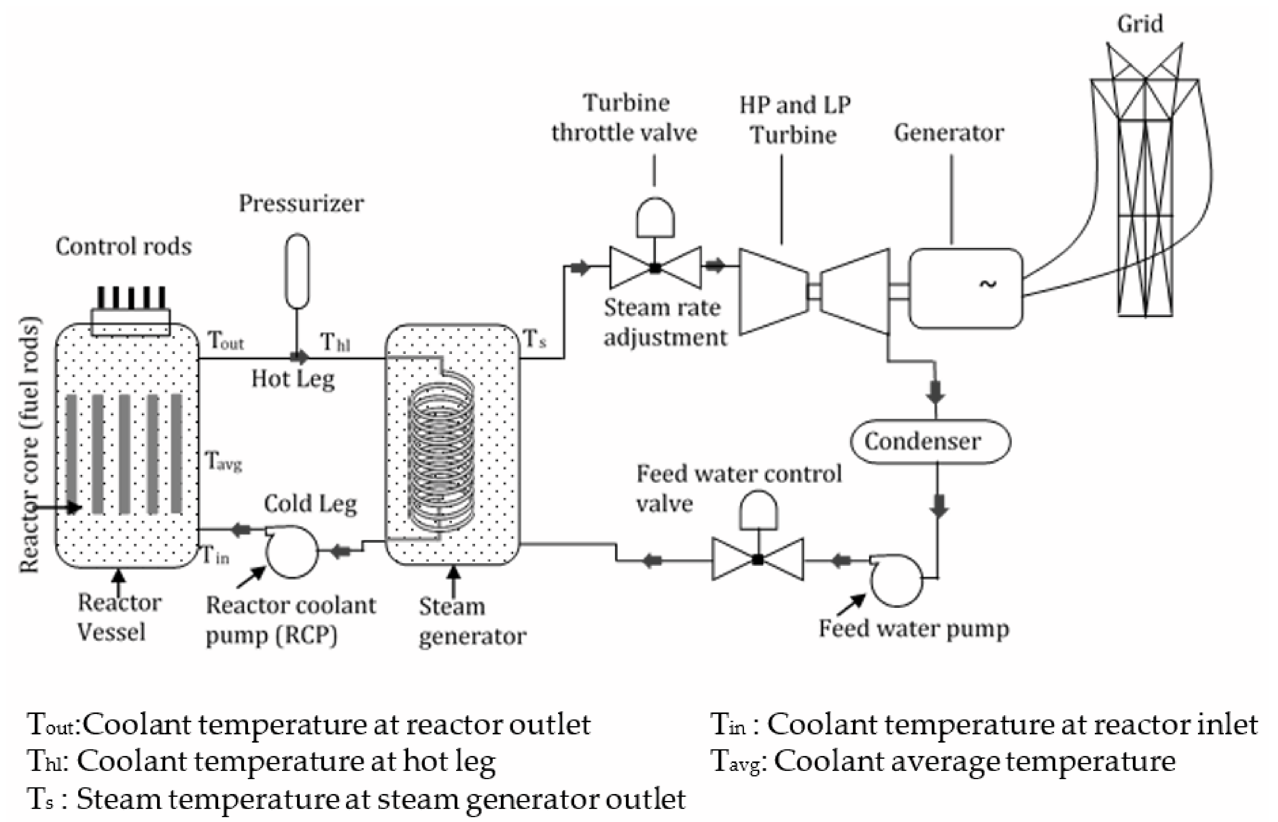
4. Requirements for the Load-Following Operation of SMRs

Since an SMR has a smaller unit capacity compared to a large nuclear reactor, thermal power control is relatively easier and less risky in terms of nuclear safety. In addition, because start up and shut down are faster, bulk output power control is possible through unit control.
Load following means changing the power generation as closely as possible to the expected power demand. Load-following generation can match demand by the output changes in a planned manner or in response to instructions or signals from the grid control center or transmission system operator (TSO). Changes in output can be large or small and frequent or infrequent [9]. The following are typical requirements for each SMR load-following mode based on the above review.

4.1. Power Change Dependent on Grid Plans

(1)
Planned Operation
This refers to the planned control of the power plant output between 20% and 80% based on the power supply and demand plan, and the output control timescale is hours or days. In some cases, the reactor output is adjusted to the level of 20% to 80% for the repair or recovery of the reactor, and the timescale in this case is hours. The power output maneuvering range is a function of time. During the first 65% of the fuel cycle, output power is controllable between 100% of nominal power and around 25% of nominal power. Then, the power control range is gradually reduced from 25% to 80% of nominal power because of excess reactivity and low boron concentrations. Nuclear power plants can operate at a minimum power level of 10%. However, the minimum output is around 20%, as for many conventional power plants [16].
(2)
Unplanned Operation
This refers to the case where the power plant output is unplanned and adjusted according to the power grid conditions, and the load-following operation is performed by controlling the output of the nuclear reactor between 20% and 80%. The timescale for TSO instruction operation is minutes.

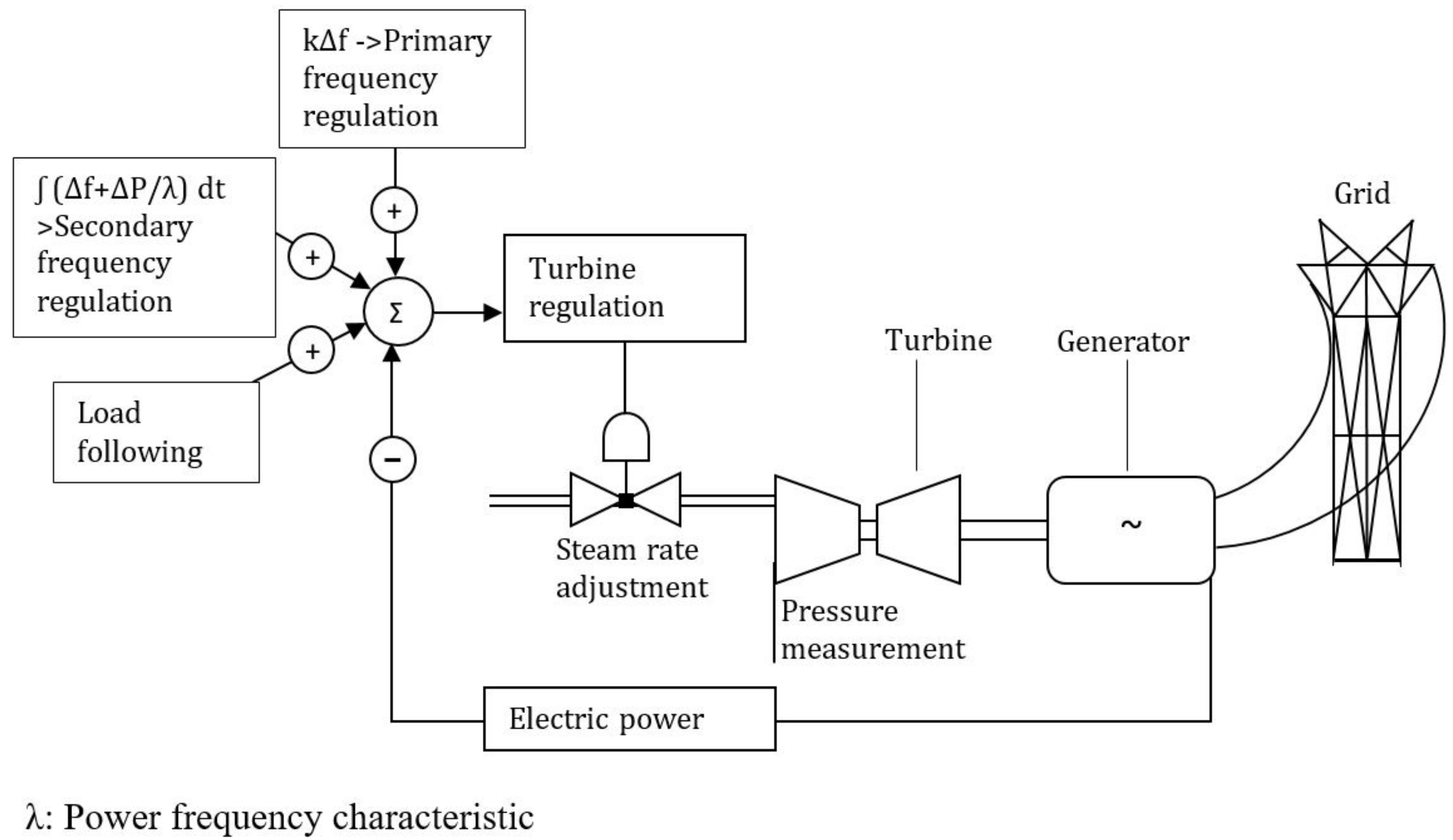
4.2. Power Change Dependent on Frequency

(1)
Automatic Generation Control (AGC)
This refers to automatically reducing or increasing plant output within a limited range according to signals from the transmission system operator (TSO). This type of operation is also referred to as the ‘Automatic Generation Control’ (AGC). The power change is typically within 20~40% of the RTP [10] or ±10% of the rated thermal power (RTP) [12], and the timescale is minutes.
(2)
Governor-Free (GF) Control
This refers to controlling frequencies outside a specified frequency range, either by reducing the generator output by the turbine governor when the system frequency exceeds the maximum limit or increasing the output when the system frequency falls below the minimum limit. The plant operator, in response to the frequency deviation, can initiate frequency control automatically or manually. The power change is typically within 20~40% of the RTP [10] or ±10% of the RTP [12], and the timescale is seconds.

4.3. Coordinated Rapid Load Following

A coordinated control approach accomplishes a rapid load-following operation by wisely combining the ‘reactor following turbine mode’ and ‘turbine following reactor mode’ along with the satisfaction of the reactivity constraints. The coordinated mode of power variation can be explained as follows:
The reactor is assumed to operate normally in the ‘reactor following turbine mode’ and at a certain power output level of Pth = Ptha, much lower than 100% full power (FP). In that condition, the output is increased to a high value of Pthb within a short time interval “T” and held to that value for the rest of the time. The coordinated mode may be due to the nature of the daily load curve. For example, where the reactor’s power has to match a growing demand, a predefined instant consumption suddenly increases [10].

4.4. Multi-Module Unit Operation

If the plant has multiple SMRs, the entire power output of the plant can be adjusted by the disconnection of some reactor modules during periods of low demand, for scheduled maintenance, or when significant, high-priority energy becomes available from intermittent renewable energy system (RES) [17]. The performance data of the SMRs are not yet verified by commercial operation, but for German nuclear power plants, at least 3 h of downtime and at least 1 h of operation have been established, taking into account the start and end times [18].

4.5. Cogeneration with Non-Electric Applications

Due to SMRs’ ability to provide CO2-free energy, applications in the district heating field are mainly being discussed. Although smaller than traditional nuclear power plants (NPPs), SMR plant designs can provide increased safety through passive systems, reduce costs, and increase quality through factory-based manufacturing and other advantages [19]. The primary side circuits of the SMR can be operated at rated capacity, and only a fraction of the heat can be converted for other purposes, such as district heating, desalination, or hydrogen production [20].
The requirements that the cogeneration SMR must have in order to perform a load-following operation are as follows: First, the distance between the SMR and the heat utilization plant should be reasonable. This is because heat is not easier to transmit than electricity. Second, the steam extraction amount and control speed suitable for SMR to perform load-following operations should be technically acceptable from the perspective of coproduction plants and be economically feasible. Third, the temperature of the steam must be adequate to produce a coproduct.
The higher the temperature, the more types of cogeneration facilities are available, so this is a key parameter. Most light water reactor (LWR) coolant outlet temperatures are around 300 °C [21]. Future high-temperature reactors can operate at higher temperatures. For example, the coolant outlet temperature of a sodium-cooled high-speed reactor is approximately 500~550 °C compared to 850~950 °C for a high-temperature gas reactor (HTGR) [22,23].

5. Other Considerations for Load Following

5.1. Regulatory Requirements

(1)
Safety Regulations
The reactor will continue to generate significant heat from the decay of fission products that persist on a logarithmic timescale, even when the chain reaction is completely stopped. The principle of providing “defense in depth” against scenarios where the NPP is unable to provide long-term core decay heat removal shall be provided [24]. US nuclear regulatory commission (US NRC) safety and licensing criteria related to electric power are contained in general design criteria (GDC) 17 [25]. The design criteria of preferred power supply (PPS) and its interface with the class 1E power system, switchyard, transmission system, and alternate ac (AAC) source are described in IEEE Std 765, ’IEEE Standard for Preferred Power Supply (PPS) for Nuclear Power Generating Stations’ [26]. IAEA safety standard series No. SSG-34, ’Design of Electrical Power Systems for Nuclear Power Plants’ [27], provides the safety guide on the necessary characteristics of electrical power systems for nuclear power plants and of the process for developing these systems.
If the safety-related systems actuate by passive means and their continued operation relies on natural cooling principles, a safety-related electrical system is not required. For this reason, NuScale requested in the license document that it be excluded from GDC 17 [28].

5.2. Technical Considerations

(1)
Physical aspects of power regulation
In terms of load following by fuel rod control, the following factors affect the maneuverability. By the moderator effect and Doppler effect, if the temperature of the primary coolant is increased, reactivity is decreased. When the reactor power increases, the power distribution is pushed to a lower part of the fuel [11]. If power variation is made by control rods, they deform the axial distribution of power and 135Xe. Thus, it is an additional challenge for the load following with large magnitudes of power variations. At the end of the fuel cycle, the margins for the maneuverability decrease because the boron concentration is almost zero and the control rods are in the upper position [11]. The use of the control rod alone for power control has negative consequences, such as flux distribution disturbance, component material fatigue, mechanical wear, and adverse impacts on the burn-up balance in the core [29].
(2)
Influence of the load following on the lifetime of components
Operating the NPP in load-following mode introduces technical disadvantages, as the plant components are exposed to numerous thermal stress cycles. This results in faster aging and requires a more sophisticated system for reactor monitoring and control [29]. Load cycling results in variations in the coolant temperature and thus in the temperatures of different components. Repeated temperature changes can create cyclic changes in the mechanical load of a part of the equipment and cause local structural damage (fatigue) to these elements. As a result, the maximal number of load-following operation cycles during the whole operational lifetime of the plant should be considered in the equipment qualification of the safety-related components [11].

5.3. Interaction of Grid Characteristics with Nuclear Power Plants

(1)
Effects of Grid Frequency Change on NPP
Changes in frequency affect NPP operation through the speed governor of the turbine generator and through the speed change in the pump that delivers the flow to the reactor and the secondary coolant circuit. If the frequency drops, the turbine/generator examines the load based on the governor droop setting and frequency deviation. The mismatch between the reactor output and the produced electric power requires intervention from the control system. As the frequency rises, the turbine speed governor closes the throttle valve on the turbine to reduce power. When the reactor output has not changed, the reactor output is greater than the power drawn by the turbine. This mismatch causes transient overtemperature and overpressure in pressurized water reactors. Modern turbines for the grids of developed countries can only operate for a few minutes at a frequency below their rated frequency. These adverse operations have a cumulative effect and are only allowed for a certain total period over the lifetime of the turbines [30].
(2)
Effect of Grid Voltage Change on NPP
A rapid voltage drop is mainly caused by electric fault on a transmission line. The magnitude of the voltage dip depends upon the distance from the fault, the type of the fault, and upon the performance of the automatic voltage regulator (AVR) of the generators connected to the grid [31]. During sharp voltage dip conditions, all motors connected to the auxiliary power system of the NPP will be retarded. The magnitude of the retardation is determined by the voltage dip and its duration, the characteristics of the motor, and the mass moment of inertia of the motor pump assembly [30].
If the grid has a light load and the NPP remains connected with long lines at the remote end, the grid voltage may be higher than generator voltage. If high grid voltage is continued for a long period, then the generator connected to the grid may be unstable because the generator must consume a large value of reactive power (Mvar). On the other hand, if the grid voltage remains low, the large motors of the NPP cannot start or can be retarded.

6. Discussion and Conclusions

Calls for a reduction in CO2 emissions triggered by the climate change crisis pose a significant challenge for most countries around the world. Therefore, all the countries have to reduce the fossil fuels that have been used to generate electricity and increase the solar and wind energies, which are called clean energy. The normative IEA net zero emission scenario (NZE) by 2050 shows a narrow but achievable path for the global energy sector to achieve net zero CO2 emissions by 2050 [32]. Developed countries reach net zero emissions before others [33]. This trend poses significant challenges in operating power grids. As the penetration of variable renewable energy (VRE) within the grid increases, many factors require greater grid flexibility to accommodate changes in generation. In particular, PV power does not generate power at night, so it has natural difficulties associated with its diurnal cycle [8]. Nuclear power generation is the most effective alternative among the ways to supply clean energy and at the same time complement the intermittent renewable energy. Due to this reason, the European Parliament decided to include nuclear and gas in the European green tax system, which was designed to promote the energy transition.
The way to supplement intermittent renewable energy is to operate nuclear power plants in a load-following mode. Large-capacity nuclear power plants are also capable of load following, but an SMR fleet is more appropriate, considering various technical and economic aspects. Therefore, this paper introduced a typical SMR currently in operation or development and elaborated various other problems in the load-following operation of the SMR. In addition, this paper specified the various requirements for an SMR load-following operation. Finally, the interaction between the SMR and the main power grid during the load-following operation of the SMR were described. In terms of the load following of SMRs, the main characteristics and contributions of this paper are that it deals with the reactor power control method, the turbine generator output control method, and the coordinated power control of the reactor and turbine generator. It is noticed that the interaction between the SMR and the main power grid is also important for the load following of SMRs.

Author Contributions

C.-k.C. wrote the paper and H.C.O. reviewed the references and conducted editorial reviews. All authors have read and agreed to the published version of the manuscript.

Funding

This research received no external funding.

Institutional Review Board Statement

Not applicable.

Informed Consent Statement

Not applicable.

Data Availability Statement

Not applicable.

Acknowledgments

This research was supported by the 2022 Research Fund of the KEPCO International Nuclear Graduate School (KINGS), Ulsan, Republic of Korea.

Conflicts of Interest

The authors declare no conflict of interest.

Abbreviations

AACAlternative AC
AGCAutomatic Generation Control
AGRAdvanced Gas-cooled Reactor
AVRAutomatic Voltage Regulator
EUREuropean Utilities Requirements
FOAKFirst of A Kind
FPFull Power
GCRGas-Cooled Reactor
GDCGeneral Design Criteria
GFGovernor-Free
GFLGrid-Following
GFMGrid-Forming
HTGRHigh-Temperature Gas-Cooled Reactor
HWRHeavy Water Reactor
LCFRLead-Cooled Fast Reactor
LNGLiquefied Natural Gas
LWRLight Water Reactor
MSRMolten Salt Reactor
NRCNuclear Regulatory Commission
NPPNuclear Power Plant
PPSPreferred Power Supply
RESRenewable Energy System
RTPRated Thermal Power
SCFRSodium-Cooled Fast Reactor
SMRSmall Modular Reactor
TSOTransmission System Operator
VREVariable Renewable Energy

References

  1. IAEA. Advances in Small Modular Reactor Technology Developments; A Booklet Supplement to the IAEA Advanced Reactors Information System (ARIS); IAEA: Vienna, Austria, 2020; p. 354. [Google Scholar]
  2. Kuznetsov, A.L.V. Current Status, Technical Feasibility and Economics of Small Modular Reactors; OECD: Paris, France, 2011. [Google Scholar]
  3. International Atomic Energy Agency. Technology Roadmap for Small Modular Reactor Deployment; NR-T-1.18; International Atomic Energy Agency: Vienna, Austria, 2021. [Google Scholar]
  4. Zohuri, B. Small Modular Reactors as Renewable Energy Sources; Springer: Cham, Switzerland, 2019. [Google Scholar]
  5. IAEA. IAEA-TECDOC-1972 Benefits and Challenges of Small Modular Fast Reactors; IAEA: Vienna, Austria, 2021. [Google Scholar]
  6. IRENA. Renewable Capacity Statistiques De Capacité Estadísticas De Capacidad; IRENA: Abu Dhabi, United Arab Emirates, 2022. [Google Scholar]
  7. U.S. Energy Information Administration. Administration. International Electricity Data. Available online: https://www.eia.gov/international/data/world (accessed on 12 July 2022).
  8. Kroposki, B.; Johnson, B.; Zhang, Y.; Gevorgian, V.; Denholm, P.; Hodge, B.M.; Hannegan, B. Achieving a 100% Renewable Grid: Operating Electric Power Systems with Extremely High Levels of Variable Renewable Energy. IEEE Power Energy Mag. 2017, 15, 61–73. [Google Scholar] [CrossRef]
  9. Pierre, I.; Lorubio, G. Flexible Generation: Backing Up Renewables; Union of the Electricity Industry-EURELECTRIC Depot legal: D/2011/12.105/47; RESAP: Paris, France, 2011. [Google Scholar]
  10. Bose, D.; Hazra, A.; Mukhopadhyay, S.; Gupta, A. A Co-ordinated Control Methodology for Rapid Load-Following Operation of a Pressurized Water Reactor Based Small Modular Reactor. Nucl. Eng. Des. 2020, 367, 110748. [Google Scholar] [CrossRef]
  11. Nuclear Energy Agency. Technical and Economic Aspects of Load Following with Nuclear Power Plants; NEA, OECD: Paris, France, 2011; pp. 1–51. [Google Scholar]
  12. IAEA (International Atomic Energy Agency). Non-Baseload Operation in Nuclear Power Plants: Load Following and Frequency Control Modes of Flexible Operation; IAEA Nuclear Energy Series; IAEA: Vienna, Austria, 2018; pp. 1–190. [Google Scholar]
  13. Ackermann, T.; Prevost, T.; Vittal, V.; Roscoe, A.J.; Matevosyan, J.; Miller, N. Paving the Way A Future without Inertial Is Closer Than You Think. IEEE Power Energy Mag. 2017, 15, 65–67. [Google Scholar] [CrossRef]
  14. Pattabiraman, D.; Lasseter, R.H.; Jahns, T.M. Comparison of Grid Following and Grid Forming Control for a High Inverter Penetration Power System. In Proceedings of the 2018 IEEE Power & Energy Society General Meeting (PESGM), Portland, OR, USA, 5–10 August 2018; pp. 1–5. [Google Scholar]
  15. Bruynooghe, C.; Eriksson, A.; Fulli, G. Load-Following Operating Mode at Nuclear Power Plants (NPPs) and Incidence on Operation and Maintenance (O&M) Costs. Compatibility with Wind Power Variability; European Commission: Luxembourg, 2010. [Google Scholar]
  16. Peakman, A.; Merk, B.; Hesketh, K. The potential of pressurised water reactors to provide flexible response in future electricity grids. Energies 2020, 13, 941. [Google Scholar] [CrossRef]
  17. Ingersoll, D.T.; Colbert, C.; Houghton, Z.; Snuggerud, R.; Gaston, J.W.; Empey, M. Can Nuclear Power and Renewables be Friends? In Proceedings of the ICAPP 2015, Nice, France, 3–6 May 2015; p. 9. [Google Scholar]
  18. Ludwig, H.; Salnikova, T.; Waas, U. Load-following Capability of German Nuclear Power Plants (NPPs). ATW Int. J. Nucl. Power 2010, 55, 4–5. [Google Scholar]
  19. World Nuclear Association. Small Nuclear Power Reactors. Available online: https://www.world-nuclear.org/information-library/nuclear-fuel-cycle/nuclear-power-reactors/small-nuclear-power-reactors.aspx (accessed on 5 May 2022).
  20. Locatelli, G.; Boarin, S.; Fiordaliso, A.; Ricotti, M.E. Load following of Small Modular Reactors (SMR) by cogeneration of hydrogen: A techno-economic analysis. Energy 2018, 148, 494–505. [Google Scholar] [CrossRef]
  21. IAEA Advanced Reactors Information System. Characteristics of Advanced Reactors. Available online: https://aris.iaea.org/sites/operating.html (accessed on 7 July 2022).
  22. Locatelli, G.; Mancini, M.; Todeschini, N. Generation IV nuclear reactors: Current status and future prospects. Energy Policy 2013, 61, 1503–1520. [Google Scholar] [CrossRef]
  23. Kunitomi, K.; Yan, X.; Nishihara, T.; Sakaba, N.; Mouri, T. JAEA’S VHTR for Hydrogen and Electricity Cogeneration: GTHTR300C. Nucl. Eng. Technol. 2007, 39, 9–20. [Google Scholar] [CrossRef]
  24. Bickel, J.H. Grid Stability and Safety Issues Associated with Nuclear Power Plants. Evergr. Saf. Reliab. Technol. 2001, 14, 1–9. [Google Scholar]
  25. USNRC. Appendix A to Part 50—General Design Criteria for Nuclear Power Plants. US Nuclear Regulatory Commission. Med. Dosim. 2020, 13, 87–93. [Google Scholar]
  26. IEEE Std 765-1983; IEEE Standard for Preferred Power Supply (PPS) for NUclear Power Generating Stations. IEEE: New York, NY, USA, 1995. [CrossRef]
  27. IAEA. Design of Electrical Power Systems for Nuclear Power Plants; Specific Safety Guide, No. SSG-34; IAEA: Vienna, Austria, 2012; pp. 1–144. [Google Scholar]
  28. NuScale Power. Nuscale SMR Technology: An Ideal Solution for Repurposing U.S. Coal Plant Infrastructure and Revitalizing Communities; NuScale Power: Corvallis, OR, USA, 2021. [Google Scholar]
  29. Wenisch, A.; Becker, O. NPP Output Flexibility Expectations in the Light of Reality; Österreichisches Ökologie-Institut: Vienna, Austria, 2010. [Google Scholar]
  30. IAEA. Interaction of Grid Characteristics with Design and Performance of Nuclear Power Plants. A Guidebook; Technical Reports Series No. 224; International Atomic Energy Agency: Vienna, Austria, 1983. [Google Scholar]
  31. Chowdhury, A.H.; Rabby, M.K.M. A study on low grid voltage problem near Rooppur nuclear power plant. In Proceedings of the 8th International Conference on Electrical and Computer Engineering, ICECE, Dhaka, Bangladesh, 20–22 December 2014; pp. 289–292. [Google Scholar]
  32. World Bank. Tracking SDG7: The Energy Progress Report 2018; World Bank: Washington, DC, USA, 2018; p. 193. [Google Scholar]
  33. OECD/IEA. World Energy Model Documentation; OECD: Paris, France, 2021. [Google Scholar]
Figure 1. Schematic of PWR Nuclear Power Plants.
Energies 15 06327 g001
Figure 2. Frequency control in a power plant.
Energies 15 06327 g002
Table 1. World Total Renewable Energy Capacity (excerpted).
Capacity
(GW)
2012201320142015201620172018201920202021
World1444156616981852201421852357254228073064
China302.1359.5414.7479.1541.0620.9695.5758.8899.61020
India60.563.671.978.690.4105.2118.2128.4134.4147.1
Japan39.046.156.167.476.284.291.399.3106.9111.9
Korea3.74.35.77.29.411.414.018.020.424.3
Table 2. Flexibility of Conventional Power Generation Technologies.
DescriptionNPPHCLignCCGPS
Start-up Time “Cold”~40H~6H~10H<2H~0.1H
Start-up Time “warm”~40H~3H~6H<1.5H~0.1H
Load Gradient (up) ”nominal output”~5%/M~2%/M~2%/M~4%/M>40%/M
Load Gradient (down) ”nominal output”~5%/M~2%/M~2%/M~4%/M>40%/M
Minimal Shutdown TimeNoNoNoNo~10H
Minimal Possible Load50%40%40%<50%~15%
Abbreviations: NPP: nuclear power plants, HC: hard coal-fired power plants, Lign: ignited-fire power plants, CCG: combined-cycle gas-fired power plants, PS: pumped storage power plants, H: hour, M: minute.
Table 3. Design Philosophy for Flexible Operation in German Light Water Reactor.
Response BaseResponse ModeParameter and Properties
Predicted daily demand variationsLoad followingLow-power period (power level and duration)
Power change rate (slow, fast)
Time in cycle (beginning, end)
Spontaneous limited demand variationsFrequency controlLocal frequency control: frequency deviation (ΔF) converted into power change (ΔP) (ΔP amplitude, slope of change)
Remote frequency control: signal from the dispatcher (ΔP amplitude, slope of change)
Superimposition of local and remote frequency control
Grid disturbancesSpinning reserveRamp (amplitude, slope, from minimum power level)
Steps (amplitude, from minimum power level)
House load capability (loss of off-site power without reactor trip)
Fast (e.g., 5% rated thermal power/minute) return to full power without advance notice
Longer-term forecasted demandExtended low-power operationReduced power level during extended period (number of occurrences, duration)
Table 4. Power Margins of European Light Water Reactor NPPs.
Common Requirements Applicable to NEW LWRsParameter
Continuous operation range (mandatory)50%~100% Pn
Down to minimum (option)20%
Primary control (mandatory); 2~30 s after deviation observed±2% Pn/min
Higher values by agreement between system operator and plant operator ± 5% Pn/min
Activating total primary range of control requested Within 30 s
Secondary control (option); several seconds to several minutes±10%
Load-Following Capabilities (option)
Load-following capability until ( ) % of whole fuel cycle 90%
Load-following range100% Pn~minimum
From full power to minimum load and back to full power operation2 per day, 5 per week
Cumulatively 200 per year
Emergency load variation (by agreement between grid operator and unit operator); amplitude down to minimum load of the unit.20% of Pn/min.
Note: Pn denotes rated power of the power plant.
Publisher’s Note: MDPI stays neutral with regard to jurisdictional claims in published maps and institutional affiliations.

