Abstract
Considering the unsafety of the present blasting network used in the blasting mining of coalfield fires, a unidirectional explosive element (named explosive diode) is proposed according to explosive logic element principles. Through theoretical and experimental analysis, the internal structure and mechanism of the unidirectional transmission of the detonation signal were studied. For an explosive diode, the length of the quenching channel was defined to be the key parameter. The explosive diode was implemented in the traditional blasting network, obtaining an explosive logic network. To evaluate the safety and reliability of the explosive diode and explosive logic network, detonation propagation and explosion-proof experiments were conducted in the lab. The optimum length of the quenching channel to obtain unidirectional detonation transmission was established. The results showed that the explosive diode could reliably control the propagation direction of the detonation signal when the length of the quenching channel was between 15 mm and 25 mm. The explosive logic network achieved a reliable detonation propagation and was explosion-proof. In comparison with traditional networks, the explosive logic network showed increased safety and reliability as the number of subnets increased. This is a significant improvement to mining safety and demonstrates great promise for engineering applications.
1. Introduction
Worldwide, coal fires with a large area, a high temperature, and a long duration occur frequently in exposed or underground coal seams [1]. In many countries, such as China [2,3], South Africa [4], India [5], USA [6] and Australia [7], coal fires cause major disaster during opencast working. Domestic and international research on coal fires primarily include the following aspects: the distribution and development of coal fires, the detection and monitoring of coal fires [8,9,10], the modelling of underground coal fires [11,12,13], assessments of the impact on the environment and human health [14] and fire-fighting engineering [15,16]. Due to different geological conditions in China compared to other countries, there are fewer studies regarding blasting mining in coalfield fires outside of China. The major coal fire areas qualified for large-scale open-air mining are located in northwest China, where the climate is generally arid and rainless, vegetation on the ground is deficient, wild species are rare, the resident population is sparse, and public infrastructure near coal mines are underdeveloped. Open mining here adopted physical cooling construction procedures before blasting mining. Safety regulations for blasting stipulate that the temperature of the blast holes must be reduced to below 80 °C before blasting operations are conducted [17]. Blasting mining is distinct from traditional blasting because of the contact time and general lack of experience with it. The blasting site has low visibility, contains high-temperature blast holes and is an unsafe working environment. A field photograph is shown in Figure 1. Recently, in Ningxia province, two serious safety accidents occurred in coalfield fires, which resulted in the death of more than 10 people and in injuries to at least 20 more. These accidents were due to the premature explosion of the subnet, resulting in the entire network being detonated [18,19]. These accidents seriously affected the mineral mining efficiency and threatened the workers at the blasting site. Therefore, it is important to improve safety techniques in the blasting network.
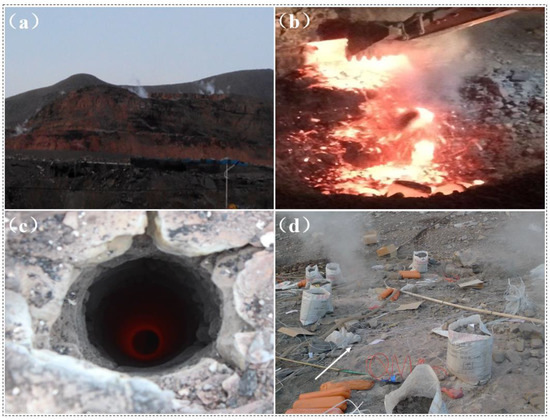
Figure 1.
Blasting mining site, field photograph, December 2021, in Dashitou coalfield fires approximately 10 km northwest of Ruqigou in Ningxia province. (a) A long-time heated open pit coal mine (the color of the mountain is dark red), (b) spontaneous combustion coal seam, (c) high-temperature blast hole (the temperature can reach 400 °C) and (d) high-temperature blasting site.
It is significant that an explosive logic network was applied to field blasting to improve the safety of the blasting network. First proposed by D. A. Silvia [20,21] in the 1960s, an explosive logic network is composed of an explosive logic element and an initiating device. This network has a gate function, can make a logical judgement about the detonation signals coming from the different input ends and decides whether to output a signal and in which way to output it. A traditional blasting network is divided into the following categories: the detonating tube network, the detonating cord network, the electric detonator network and the hybrid network. In the design of a blasting network for coalfield fires, the blast holes are located in different high-temperature environments. After the implementation of physical cooling or resistant heat protection measures, the electric detonator and detonating tube networks are still not suitable for usage. By comparison, when adopting an RDX as the explosive, the detonating cord exhibited reliable detonation propagation and high-temperature endurance [22,23]. It is the optimal initiating equipment in the network design. In a traditional blasting network, the detonation signal can propagate bidirectionally. This is to say that the detonation signal can propagate from the main network to the subnet under conventional blasting. Similarly, it is able to detonate the main network when the detonation signal error is inputted from the subnet. Therefore, a traditional blasting network poses some potential hazard. In this paper, an element named explosive diode, which has a gate function that controls the propagation direction of the detonation signal, was designed. An explosive diode is a connector within the detonating cord network. Previously, some researchers studied the connector applied to the detonating fuse blasting network. Bartholomew S W et al. proposed a blasting signal transmission tube delay unit related to a time delay assembly [24], and Zakheim H put forward bidirectional delay connectors related to the time delay in the detonating cord network [25]. This connector mainly plays a time delay role, and research on the size of the detonation elimination chamber is limited. The author adopted the detonation elimination chamber structure and the shock initiation structure of a flying plate type in the detonation sequence [26]. Since conventional high explosives inside the explosive diode were not used, this structure was highly safe. In the experiments, the explosive diode can be applied to a traditional blasting network to form an explosive logic network, which performs well in field blasting. To evaluate the safety and reliable performance of the explosive diode and the explosive logic network, detonation propagation and explosion-proof experiments were performed by simulating a field-blasting network in the lab. Moreover, we conducted a theoretical calculation comparing the reliability of the new and the traditional networks. From the results of these experiments and the above calculation, the application of explosive logic networks would greatly increase the safety and efficiency of blasting mining in coal fire areas.
2. Composition of the Unidirectional Explosive Element
As shown in Figure 2, the unidirectional explosive element (named explosive diode) is composed of a metal shell (2), sealing elements (1 and 8) at both ends of the element, the input end of the detonation signal (14, End A), a hollow rubber structure (13), sealing wax paper (4), an excitation setting (5), an explosion-proof structure (6), and the output end of the detonation signal (7, End B). The relevant parameters of the initiating equipment (End A and End B) used in the experiment mentioned in this paper are listed in Table 1. The different densities of the layered charge in the explosion-proof structure 6 are listed in Table 2 [27]. The metal shell should possess sufficient strength to resist internal detonating and deflagrating reaction forces, as well as the longitudinal forces that may be applied during the detonation signal propagation. The preferred material is steel tubing. When the detonating cord (7 or 14) was inserted into the sealing element (1 or 8), a locking phenomenon could be produced. The tight fit between the detonating cord and the sealing element is waterproof and performs a fixed connecting function. The interior of the hollow rubber structure 13 forms an air channel called quenching channel (3). This quenching channel functions to control the shock wave attenuation from one side of the hollow rubber structure to the other. The sealing wax paper (4) prevented the excitation powder (11) from spilling. The excitation setting (5) was positioned directly abutting the quenching channel (3) and the second charge (10) to receive and transmit the blasting initiation signal. The explosion-proof structure (6) functioned to transmit the shock wave signal from the quenching channel (3) to the detonating cord of End B. Similar to the function of a diode in an electronic circuit, this element only allows a one-way transmission of the detonation signal and can also be called explosive diode. When the elements are connected to the blasting network, two connections are possible: forward connection and reverse connection. In the case of a forward connection to the blasting network, the detonation signal is input from end A and output from end B; this can realize a forward detonation transmission. In the case of a connection to the blasting network in reverse, the detonation signal is successfully blocked after being input from end B to realize reverse detonation suppression.
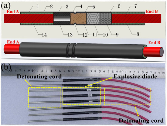
Figure 2.
The unidirectional explosive element (explosive diode), (a) schematic, 1 and 8—Sealing element, 2—Metal shell, 3—Quenching channel, 4—Sealing wax paper, 5—Excitation setting, 6—Explosion-proof structure, 7—Output end of detonation signal, 9—1st Charge, 10—2nd Charge, 11—Excitation powder, 12—Bayonet fixing, 13—Hollow rubber structure, 14—Input end of detonation signal, (b) sample.

Table 1.
Initiating equipment (End A and End B).

Table 2.
Layered structure’s charge densities.
3. Experimental Methods and Results
In this paper, reliable explosion propagation and explosion-proof experiments were carried out by verifying the iron plate explosion propagation method (judging the propagation of the detonation signal by the explosion trace on the iron plate), and the application range of the key parameters of the unidirectional explosion element was obtained. Based on the unidirectional explosion propagation model, the explosive logic network was designed. The logic function of the unidirectional explosive element in the explosion network was also confirmed by reliable explosion propagation and explosion-proof experiments. At the same time, the reliability of the traditional explosive network and the explosive logic network was analyzed. The flow diagram of the experimental methods is shown in Figure 3.
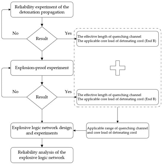
Figure 3.
Flow diagram of the experimental methods.
3.1. Experiment to Evaluate the Reliability of the Detonation Propagation
Through the detonation propagation experiment, the explosive diode accessed the network through a forward connection. In Figure 4, the propagation direction of the detonation signal is indicated by an arrow (i.e., from End A to End B), and the configuration is shown.

Figure 4.
Configuration of the detonation propagation experiment, 1—detonator, 2—detonating cord of end A, 3—explosive diode, 4—detonating cord of end B, 5—the thickness of 0.2 mm iron-plate.
In the process of detonation propagation, a reliable detonation wave propagation is the desired goal. The key parameters within this element contain the detonating cord of End B with different core loads and quenching channel lengths. As shown in Figure 4, an industrial detonating cord weighing 14 g per meter was inserted into End A and End B. The element selected a 10 mm quenching channel, and the End B detonating cord was connected to a 0.2 mm experimental iron plate. An 8# industrial detonator ignited the detonating cord of End A to test whether the detonation signal could propagate successfully from End A to End B.
Based on the experiments shown in Figure 5, multi-group experiments were conducted to test the effect on the detonation propagation by adjusting the length of the quenching channel and by using different liner densities of the detonating cord at End B. The results of these experiments are listed in Table 3.

Figure 5.
Successful detonation propagation experiments.

Table 3.
Detonation propagation results using different design parameters.
Considering Figure 5 and Table 3, we concluded that the explosive diode could reliably allow detonation propagation from End A to End B to achieve a gate function, and the experimental iron plate was successfully destroyed, as shown in Figure 5. The propagation process of the detonation signal was as follows. First, a stable detonation signal was inputted from the detonating cord of End A; then, it was transformed to a shock wave after passing through the quenching channel. Finally, this shock wave triggered the excitation setting of the sublayer charge structure to ignite the End B detonating cord, whose core load ranged from 2.4 g per meter to 14 g per meter.
3.2. Explosion-Proof Experiment
With the experimental method described above, the element accessed the experimental networks following a reverse connection. The propagation direction of the detonation signal is indicated by an arrow (i.e., from End B to End A) in the structure diagram shown in Figure 6.

Figure 6.
Structure diagram of the explosion-proof experiment, 1—detonator, 2—detonating cord of end B, 3—explosive diode, 4—detonating cord of end A, 5—the thickness of 0.2 mm iron-plate.
In the explosion-proof experiment, the desired goal was for the element to prevent the propagation of a detonation signal reliably from End B for different core loads of the End B detonating cord and quenching channel lengths. The explosion-proof experiment for the explosive diode was performed as shown in Figure 7 and Figure 8. An 8# industrial detonator was used to ignite the End B detonating cord and test whether the detonation signal could be prevented during the propagation from End B to End A.

Figure 7.
Failed explosion-proof experiments.

Figure 8.
Successful explosion-proof experiments.
Based on the experiments shown in Figure 7 and Figure 8, multi-group experiments to test the explosion-proof effect by adjusting the length of the quenching channel and by varying the core load of the End B detonating cord were performed. The results of these experiments are listed in Table 4.

Table 4.
Explosion-proof results using different design parameters.
From Figure 7 and Figure 8 and Table 4, when the length of the quenching channel was 10 mm and the core load of the End B detonating cord was 9.7 g per meter or above, it was concluded that the element could not reliably prevent the reverse propagation of the detonation signal. The experimental iron plate was destroyed, as shown in Figure 7. When the length of the quenching channel was between 15 mm to 25 mm, the element could reliably prevent the reverse propagation of the detonation signal. The detonation signal failed to ignite the End A detonating cord, and the element realized its explosion-proof function, as shown in Figure 8.
3.3. Explosive Logic Network Design and Experiments
The explosive logic network (new network) consisted of an ignition end, a main network (detonating cord), a subnet (detonating cord) and an explosive diode, as shown in Figure 9. In comparison with a traditional blasting network, the explosive logic network had a higher level of safety in the gate function.
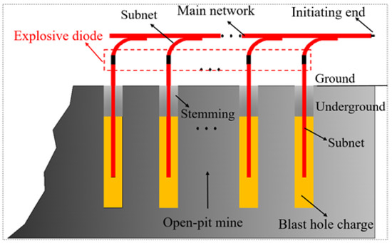
Figure 9.
Schematic diagram of the application of the new explosive logic network.
In the explosive logic network, the objective was to control the unidirectional propagation of the detonation signal in the blasting network. An explosive diode element, which played an important role as a logic control switch, connected the main network to the subnet according to a forward connection. The propagation of the detonation signal included the following processes: inputting from the ignition end, passing through the main network and the explosive diode and propagating into the subnet of the blast hole. If a premature explosion occurred in the subnet, the detonation signal would be halted when it passed through the element in according to a reverse propagation to protect the safety of the main network. The explosive logic network was utilized to simulate a field-blasting network. The main network was similar to the ground-blasting network, and each subnet was similar to the charge holes. The experimental iron plate represented the blasting effect of a blast hole. In the detonation propagation experiments of this new network, when the detonation signal was inputted from the ignition end, it could pass through the main network smoothly, and the explosive diode detonated each subnet reliably. Five obvious explosion imprints in the iron plate indicated that the reliable explosion met the network design for field blasting. The experimental apparatus and results are shown in Figure 10.
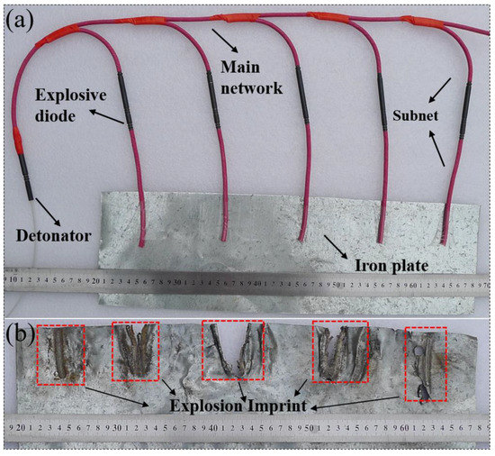
Figure 10.
Network of the detonation propagation experiment (a) and results (b).
In the explosion-proof experiments, the sudden spontaneous firing or premature explosion of the blast subnet in coalfield fires due to accidents (such as high temperature, electro discharge, or stray current) caused by the subnet was simulated. From the explosion imprint on the experimental iron plate and the explosive diode, the propagation of the detonation signal was halted and did not arrive at the main network. The integrity of the rest of the network was protected, and the explosion of the entire blasting network was avoided. The experimental apparatus and results are shown in Figure 11. This experiment demonstrated that the blast logic network has a high safety in engineering blasting and is able to protect the staff at the blasting site.
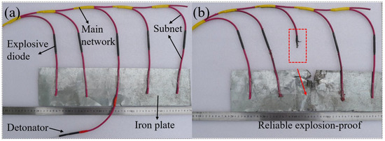
Figure 11.
Network of the explosion-proof experiment (a) and results (b).
3.4. Reliability Analysis of the Explosive Logic Network
A reliability analysis [28] that compared the traditional blasting network with the new network was made. In a traditional network, connection reliability between the subnet and the main network is equal to that of a serial network. The reliability of a subnet is defined as Pi (i.e., the reliability of every subnet is P1, P2, P3, …, Pn). The reliability of the main network is P and is indicated in the formula (1).
In the explosive logic network, the connection reliability between the subnet and the main network equals that of a parallel network. The reliability of the main network is P and is shown in the formula (2).
In the above formulas, n is the number of subnets. The reliability of a subnet was assumed to be 0.9990, and the reliability of the two networks with a different number of subnets was compared and is shown in Table 5.

Table 5.
Comparison of the reliability of two types of blasting networks.
As shown in Table 5, the reliability of a traditional network decreased as the number of subnets increased. When the number of subnets reached 50, the reliability of a traditional network was 0.9512, whereas the reliability of the new network was 0.9999. In a traditional network, the propagation of the detonation signal was bidirectional (i.e., two-way propagation), and the error input of the detonation signal from any subnet could trigger a premature explosion in the main network. In the explosive logic network, the propagation of the detonation signal was unidirectional (i.e., one-way network), and every explosive diode played the role of a controlling switch and stopped the input of errors from the subnet to protect the main network, as shown in Figure 11b. This new type of network, whose safety and reliability were demonstrated to be higher than those of a traditional one, is more suitable for blasting mining in coalfield fires.
4. Analysis of the Propagation Mechanism of the Unidirectional Explosive Element
The detonation propagation mechanism is illustrated as follows. First, the stable detonation signal was inputted from the detonating cord of End A, and then the detonation signal was transformed to a shock wave when it passed through the quenching channel. Finally, the shock wave and high-temperature gas products ignited the excitation powder in the established excitation setting. As the heat accumulated, local hot spots formed and developed into combustion in a short time. Large amounts of gas were produced and resulted in a high temperature and high pressure in the examined excitation setting [29]. Afterwards, a slapper with a high velocity formed from the bottom in the considered excitation setting at a high temperature and a high pressure. Finally, the slapper struck the layered charge with different densities (2nd charge and 1st charge) in the examined excitation setting, allowing the propagation of the detonation. In the process of detonation propagation, the sensitivity of the charge in the explosion-proof structure was reduced from a high level to a low level, and the detonation energy increased from a low level to a high level. Therefore, a stable detonation energy ignited the initiating device, and detonation propagation was achieved.
The explosion-proof mechanism is illustrated as follows. If the detonation signal was inputted from the detonating cord of End B, it passed through the explosion-proof structure from the reverse direction, and the detonation energy was greatly reduced under the conditions where there was a lack of hot spots and a low detonation sensitivity for the first insensitive charge. Therefore, the detonation energy of End B could not ignite the initiating device at End A because the sympathetic detonation was attenuated in the quenching channel, and the system was therefore explosion-proof in the reverse direction.
Analysis of the quenching channel length was carried out. If the quenching channel was short, the detonation signal from End B attempted to detonate the initiating device at End A with a sympathetic detonation. The element would directly ignite the detonating cord of End A when there was a great amount of energy in the sympathetic detonation and therefore lost the explosion-proof feature. On the contrary, if the quenching channel was long, the detonation signal would reduce excessively and could not ignite the next excitation setting needed for the detonation signal to propagate smoothly from End A to End B. The results of the multi-group experiments were analyzed. If the quenching channel was longer than 25 mm, the reliability of detonation propagation was low. If the quenching channel was shorter than 15 mm, the reliability of the explosion-proof system was low. Therefore, a length of the quenching channel between 15 mm and 25 mm should be selected for the optimal design of the element.
5. Conclusions
In this paper, an explosive diode as an element of detonation propagation was designed and added to a traditional blasting network to form a new explosive logic network. To evaluate the performance of this new network, detonation propagation and explosion-proof experiments were performed. Moreover, the reliability of the two networks was analyzed and compared. Some key points are as follows:
- (1)
- An explosive element (named explosive diode) with unidirectional detonation signal transmission function was designed. The internal charge structure and detonation sequence of the element were described in detail, and the unidirectional explosive propagation of the element was analyzed. The optimal length of the quenching channel was demonstrated to be between 15 mm and 25 mm. In the detonation propagation experiments, the explosive diode could reliably propagate the detonation signal in the forward direction and successfully prevent the reverse propagation of the detonation signal. When the length of the quenching channel was 10 mm and the core load of the End B detonating cord was 9.7 g per meter or higher, it was concluded that the element could not reliably prevent the reverse propagation of the detonation signal.
- (2)
- In the detonation propagating experiments of the explosive logic network, the detonation signal could successfully pass through the explosive diode to detonate each subnet reliably. Moreover, in the explosion-proof experiments, the propagation of the detonation signal was halted by the explosive diode, the main network was not ignited, and therefore, the explosive diode protected the rest of the network and avoided the premature explosion of the entire blasting network. The reliability of explosive logic network and traditional explosive network was analyzed. With the increase of the number of subnets, the reliability of the explosive logic network appeared greater than that of the traditional explosive network. The explosive element and explosive logic network can be applied to engineering environments prone to premature explosion or sudden spontaneous firing, such as high-temperature coal mine blasting, blast furnace nodulation blasting, high-temperature tunnel blasting, and can improve the safety and productivity of blasting operations.
Author Contributions
Methodology and writing—original draft, F.W.; validation and data curation, H.M.; writing—review and editing, and Z.S. All authors have read and agreed to the published version of the manuscript.
Funding
This research was funded by the Natural Science Foundation of the Anhui Higher Education Institution (No. KJ2021A0461), the Independent subject of State Key Laboratory of Mining Response and Disaster Prevention and Control in Deep Coal Mines (No. SKLMRDPC20ZZ07), the Anhui Province Natural Science Foundation (No. 2108085QA40), University-level key projects of Anhui University of science and technology (No. xjzd2020-03), the Institute of Energy, Hefei Comprehensive National Science Center (Grant No. 21KZS216).
Data Availability Statement
Not applicable.
Acknowledgments
The authors gratefully acknowledge the CAS Key Laboratory of Mechanical Behavior and Design of Materials that contributed to the research results reported within this paper.
Conflicts of Interest
The authors declare no conflict of interest.
References
- Kuenzer, C.; Stracher, G.B. Geomorphology of coal seam fires. Geomorphology 2012, 138, 209–222. [Google Scholar] [CrossRef]
- Song, Z.; Kuenzer, C. Coal fires in China over the last decade: A comprehensive review. Int. J. Coal Geol. 2014, 133, 72–99. [Google Scholar] [CrossRef]
- Su, H.T.; Zhou, F.B.; Shi, B.B.; Qi, H.N.; Deng, J.C. Causes and detection of coalfield fires, control techniques, and heat energy recovery: A review. Int. J. Miner. Metall. Mater. 2020, 27, 275–291. [Google Scholar] [CrossRef]
- Bell, F.G.; Bullock, S.E.T.; Halbich, T.F.J.; Lindsay, P. Environmental impacts associated with an abandoned mine in the Witbank Coalfire, South Africa. Int. J. Coal Geol. 2001, 45, 195–216. [Google Scholar] [CrossRef]
- Agarwal, R.; Singh, D.; Chauhan, D.S.; Singh, K.P. Detection of coal mine fires in the Jharia coal field using NOAA/AVHRR data. J. Geophys. Eng. 2006, 3, 212–218. [Google Scholar] [CrossRef]
- Stracher, G.B.; Taylor, T.P. Coal fires burning out of control around the world: Thermodynamic recipe for environmental catastrophe. Int. J. Coal Geol. 2004, 59, 7–17. [Google Scholar] [CrossRef]
- Ellyett, C.D.; Fleming, A.W. Thermal infrared imagery of the Burning Mountain coal fire. Remote Sens. Environ. 1974, 3, 79–86. [Google Scholar] [CrossRef]
- Zhang, J.; Wagner, W.; Prakash, A.; Mehl, H.; Voigt, S. Detecting coal fires using remote sensing techniques. Int. J. Remote Sens. 2004, 25, 3193–3220. [Google Scholar] [CrossRef]
- Guha, A.; Kumar, K.V.; Kamaraju, M.V.V. A satellite-based study of coal fires and open-cast mining activity in Raniganj coalfield, West Bengal. Curr. Sci. 2008, 95, 1603–1607. [Google Scholar]
- Du, B.; Liang, Y.; Tian, F. Detecting concealed fire sources in coalfield fires: An application study. Fire Saf. J. 2021, 121, 103298. [Google Scholar] [CrossRef]
- Huo, H.; Jiang, X.; Song, X.; Li, Z.L.; Ni, Z.; Gao, C. Detection of coal fire dynamics and propagation direction from multi-temporal nighttime Landsat SWIR and TIR data: A case study on the Rujigou coalfield, Northwest (NW) China. Remote Sens. 2014, 6, 1234–1259. [Google Scholar] [CrossRef] [Green Version]
- Roy, P.; Guha, A.; Kumar, K.V. Structural control on occurrence and dynamics of Coalmine fires in Jharia Coalfield: A remote sensing based analysis. J. Indian Soc. Remote Sens. 2015, 43, 779–786. [Google Scholar] [CrossRef]
- Fei, J.; Wen, H. Experimental research on temperature variation and crack development in coalfield fire. Combustion 2017, 28, 29. [Google Scholar] [CrossRef]
- Cheng, X.J.; Wen, H.; Xu, Y.H.; Fan, S.X.; Ren, S.J. Environmental treatment technology for complex coalfield fire zone in a close distance coal seam—A case study. J. Therm. Anal. Calorim. 2021, 144, 563–574. [Google Scholar] [CrossRef]
- Lu, X.; Wang, D.; Qin, B.; Tian, F.; Shi, G.; Dong, S. Novel approach for extinguishing large-scale coal fires using gas–liquid foams in open pit mines. Environ. Sci. Pollut. Res. 2015, 22, 18363–18371. [Google Scholar] [CrossRef] [PubMed]
- Shao, Z.; Wang, D.; Wang, Y.; Zhong, X.; Tang, X.; Hu, X. Controlling coal fires using the three-phase foam and water mist techniques in the Anjialing Open Pit Mine, China. Nat. Hazards 2015, 75, 1833–1852. [Google Scholar] [CrossRef]
- GB 6722-2014; Safety Regulations for Blasting. China National Standardization Management Committee: Beijing, China, 2014.
- The Office of the Safety Committee of the State Council Reported the “10.16” Blasting Accident in Dafeng Open Pit Mine. Available online: http://www.gov.cn/jrzg/2008-10/21/content_1126202.htm (accessed on 21 October 2008).
- Notification on the “10.14” Major Explosive Explosion Accident in Dafeng Open Pit Mine of Shenhua Ningmei Group. Available online: https://www.chinamine-safety.gov.cn/zfxxgk/fdzdgknr/sgcc/sgtb/202004/t20200401_350496.shtml (accessed on 12 October 2009).
- Silvia, D.A.; Ramsey, R.T.; Spencer, J.H. Explosive Gate, Diode and Switch. U.S. Patent 3,430,564, 4 March 1969. [Google Scholar]
- Silvia, D.A. Explosive Logic Network. U.S. Patent 5,311,819, 17 May 1994. [Google Scholar]
- Liao, M.Q.; Sun, F.Q. Applications of Common Detonating Fuses in High-Temperature Blasting Jobs. Explos. Mater. 1991, 20, 19–21. (In Chinese) [Google Scholar]
- Lee, J.S.; Hsu, C.K.; Chang, C.L. A study on the thermal decomposition behaviors of PETN, RDX, HNS and HMX. Thermochim. Acta 2002, 392, 173–176. [Google Scholar] [CrossRef]
- Bartholomew, S.W.; Rontey, D.C.; Necker, W.J.; Adams, C.F. Blasting Signal Transmission Tube Delay Unit. U.S. Patent 4,742,773, 10 May 1988. [Google Scholar]
- Zakheim, H. Bidirectional Delay Connector. U.S. Patent 3,727,552, 17 April 1973. [Google Scholar]
- Du, J.G.; Ma, H.H.; Shen, Z.W. Laser Initiation of Non-Primary Explosive Detonators. Propellants Explos. Pyrotech. 2013, 38, 502–504. [Google Scholar] [CrossRef]
- Mei, Q. Study on Key Technology and Application of Low Energy Detonating Fuses. Ph.D. Thesis, University of Science and Technology of China, Hefei, China, 2007. [Google Scholar]
- Cui, X.; Li, Z.; Zhou, T.; Shen, Z. Reliability Analysis of Large-scale Priming Circuit Used in Blasting Demolition. Blasting 2012, 2, 030. (In Chinese) [Google Scholar]
- Starkenberg, J. Ignition of solid high explosive by the rapid compression of an adjacent gas layer. In Proceedings of the Seventh Symposium (International) on Detonation, Annapolis, MD, USA, 16–19 June 1981; pp. 3–16. [Google Scholar]
Publisher’s Note: MDPI stays neutral with regard to jurisdictional claims in published maps and institutional affiliations. |
© 2022 by the authors. Licensee MDPI, Basel, Switzerland. This article is an open access article distributed under the terms and conditions of the Creative Commons Attribution (CC BY) license (https://creativecommons.org/licenses/by/4.0/).