1. Introduction
The gearbox is an important part of the transmission system, which has the function of power transmission and changing the transmission ratio and can ensure the smooth operation of the transmission system under different working conditions [
1,
2,
3]. The transmission efficiency and lubrication state of the gearbox are the technical indicators that affect the performance of the whole machine and have an important impact on the power, economy and environmental performance. Planetary gear transmission has its unique characteristics under the same conditions as part material, machining accuracy and working environment [
4,
5,
6]. Especially for transmission devices such as machine tools that require small size, light weight, compact structure and high transmission efficiency, planetary gear transmission has been more and more widely used. However, there will still be some problems during use, such as: poor load sharing performance of the planetary gearbox; serious wear of the gears in the planetary gear train [
7]. At the same time, for planetary gear transmission, especially the planetary gear gearbox with complex mechanisms, efficiency is one of the important quality indicators of planetary gear transmission. In the process of planetary gear design, whether the efficiency and power flow of the planetary row are reasonable, and whether there is a closed power flow are issues that must be considered. In addition, the changing characteristics of the meshing force on the gears, the dynamic stress generated by the impact on the gears during shifting, and the dynamic characteristics of the key nodes of the gear teeth are also issues that people pay attention to. There is a large impact phenomenon when the transmission system shifts, resulting in poor comfort [
8,
9,
10]. Therefore, it is of great practical significance to study the shifting performance of construction machinery gearboxes, improve the shifting stability and shorten the shifting time, and it is currently a research hotspot in this field.
Due to the rapid development of computers and the application of corresponding analysis software, more and more experts and scholars have begun to apply new technologies and methods to analyze and study planetary gearboxes [
11]. The planetary gearbox produces vibration and shock during the shifting process, and the optimal design of the shifting process has also become one of the focuses of planetary gearbox research. From the research in recent years, the research on transmission efficiency and power flow has gradually increased. These studies mainly focus on two aspects: on the one hand, by studying some theoretical methods, it is easier to analyze and mark the flow direction of power flow [
12,
13,
14,
15]. On the other hand, through theoretical analysis, the speed, torque and efficiency variation characteristics of the main components of the planetary gearbox in different gears are obtained [
16,
17,
18,
19]. These studies have provided a very important theoretical basis for later generations, but at the same time, different gearbox structures, different transmission ratios, and different gearbox efficiencies are all different. Due to the friction between the gears, the temperature field of the gear system must be taken care of. Thermal stress caused by temperature rise is a necessary calculation condition to analyze the thermal fatigue of gears and gear shafts, and even bearings and housings [
20,
21,
22]. Using CFD simulation analysis technology, detailed flow field information can be obtained in the early stage of research and development, and then with low cost and accurate simulation results, it can help realize the forward design of gear transmission lubrication systems [
23,
24,
25].
With the increase of the transmission power of the gear transmission and the increase of the speed, the power loss caused by the gear transmission is still quite large. The loss of power is not only uneconomical but also causes the machine to heat up, and aggravates the wear and vibration of the machine, resulting in reduced working life and reliability of the machine [
26]. Therefore, it is of great theoretical and practical significance to study and improve the efficiency of gear transmission. In order to improve the gearbox shift performance, the gearbox uses the method of installing a pressure regulator in the hydraulic circuit, so that the oil pressure drops rapidly at the moment of shifting. After the gear shift is completed, the oil pressure is gradually restored to the control pressure, so as to achieve the purpose of reducing the impact of gear shift and smooth transition [
27]. The node analysis method can be used to quickly determine the power size and flow direction of the planetary gearbox, which provides a certain theoretical reference for analyzing whether the flow direction of each gear of the gearbox is reasonable and whether there is a closed power flow [
28]. After optimizing the gear parameters of the planetary platoon of the AT transmission, the efficiency of the planetary platoon is significantly improved by optimizing the gear parameters of the planetary platoon of the AT transmission [
29,
30,
31].
In this paper, the quality of gear shift is optimized based on a multi-objective genetic algorithm based on the optimization goal of impact and sliding motor. Through the simulation of shift quality, the power interruption phenomenon during the shift process is eliminated, thereby improving the shift quality. In order to improve the smoothness of shifting, it is necessary to avoid excessive impact load on the gearbox caused by instant acceleration or instant deceleration and to reduce the speed loss during shifting. The key gears in the gearbox are made flexible, and the rigid-flexible hybrid model of the gearbox is established to analyze the various characteristics of the meshing force of the planetary gear teeth. The stress distribution of gear teeth and the stress dynamic characteristics of key nodes of gear teeth were explored. The rotational speed, torque variation characteristics, transmission efficiency and total transmission efficiency of gearboxes of each planetary row under the same gear are analyzed. Finally, the stress distribution of the sun gear at the maximum impact time and the stable stage, and the dynamic stress–time history of the key nodes of the sun gear are obtained, which lays the foundation for the fatigue strength and life prediction of the gear system.
2. Gearbox Co-Simulation Model
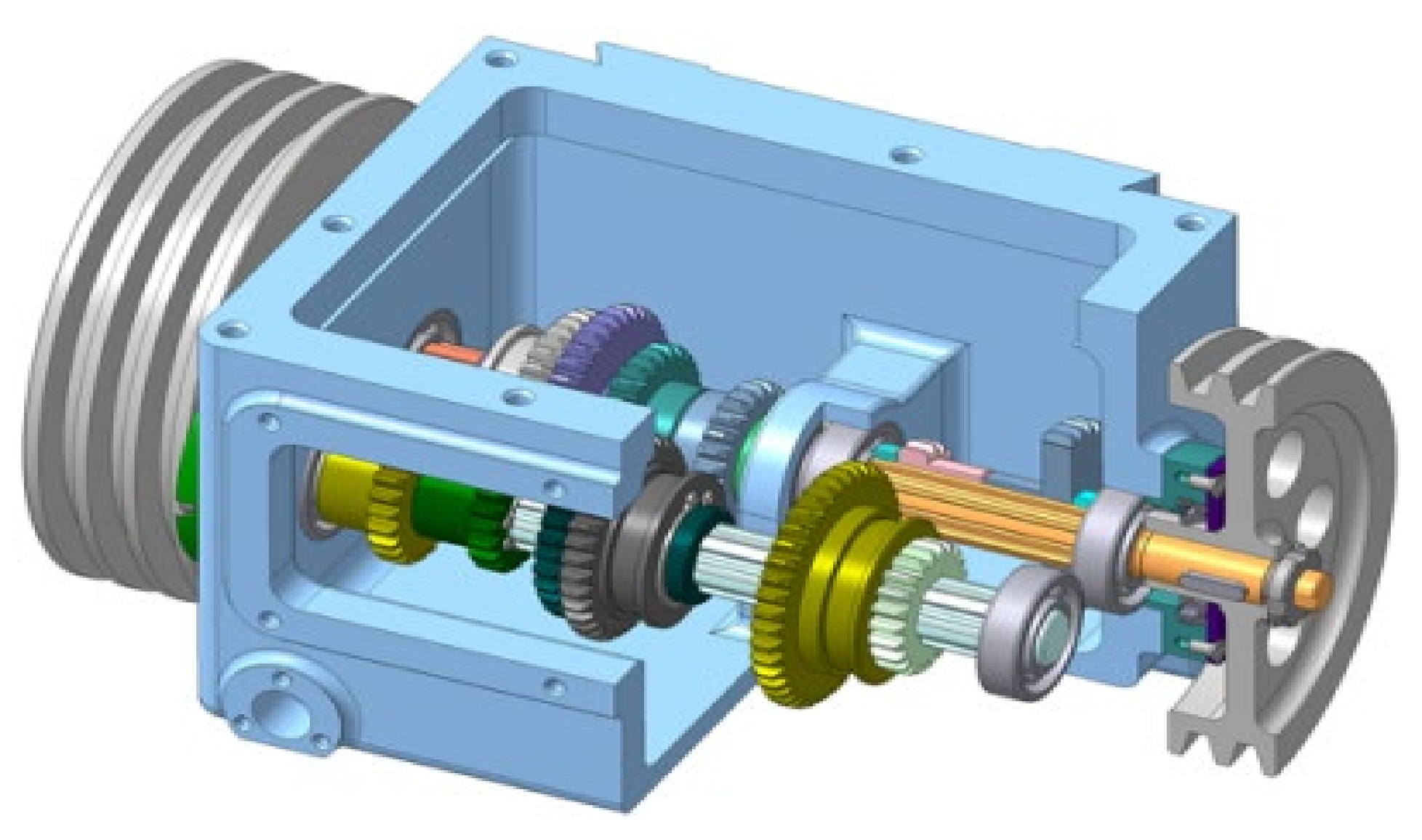
The mechanical structure of the gearbox consists of housing, an end cover, a large and small gear, a bearing, a shaft and other accessories, as shown in
Figure 1. One of the functions of the planetary gearbox is to change the transmission ratio, expand the range of torque and speed of the driving wheel, and adapt to frequently changing working conditions. Analysis of the transmission ratio of the gearbox is the primary part of the study of the gearbox, and it is also a necessary premise to study the force of each component in the gearbox and the transmission efficiency of the gearbox. The model of the mechanical transmission part of the gearbox is mainly the gear transmission part and the clutch part. The key to modeling is to ensure that the power transmission route is accurate to ensure the accuracy of the transmission ratio of each gear. According to the working principle diagram of the gearbox, the simulation model of the transmission part is established as shown in
Figure 2. Since the established model in the standard library ignores the moment of inertia of the gear, and the moment of inertia is of great significance to the shifting of the gearbox, the influence on shifting should be taken into account when establishing this part of the model, and the corresponding parameters should be set. This dissertation focuses on the speed torque characteristics, transmission efficiency and gear meshing force characteristics of each planetary row of the planetary gearbox under various working conditions. The simulation model established by Simulink cannot obtain the relevant characteristics effectively, so the virtual prototype model of the gearbox is established. The planetary gearbox has many meshing gears, and the gear teeth are frequently impacted during the frequent shifting operations. In practical engineering problems, there are large-scale rigid body motions and small-scale elastic deformations of components. The modeling theory of multi-rigid body dynamics cannot fully and effectively reflect the force changes during gear meshing. In previous studies, it was found that the second planetary row working gear in the planetary gearbox received the largest impact and meshing force during stable operation [
32]. In this paper, the planetary sun gear is made flexible, and the stress distribution and stress dynamic characteristics from start to stable operation are analyzed.
3. Multi-Objective Optimization of Shift Quality
Taking impact degree and sliding friction power as optimization goals, clutch pressing force change rate and shifting time as control variables, a genetic algorithm is used to optimize the shifting quality with multiple objectives, in order to obtain the best shifting performance. The expressions of impact degree and sliding friction work are [
33]:
Fitness function:
where:
and
are the weight coefficients of the impact degree and the sliding friction work, respectively;
represents the value of the impact degree;
represents the value of the sliding friction work;
T is the output shaft torque of the gearbox;
I is the moment of inertia of the output shaft of the gearbox;
is the transmission ratio from the transmission to the wheel;
R is the radius of the wheel;
is the clutch friction torque;
is the angular velocity of the clutch follower; and
is the angular velocity of the clutch active plate.
Restrictions:
where:
represents the value of the clutch clamping force;
t represents the shift time.
The optimization problem is solved by applying genetic algorithms, where the number of populations is set to 10, the rate of variation is 0.1, and the crossover rate is 0.5. Follow the steps of genetic algorithm encoding, decoding, selection, crossover, variation, etc. The fitness function requires a single-valued, continuous, non-negative, maximized, linear scale transformation from the objective function to the fitness function:
where: the coefficient
a is negative and
b is the amount of regulation;
J is the target function value.
By turning the minimization solution of the objective function into a maximum solution of the fitness function, the fitness function
F is not negative. For this optimization problem, we choose
a as −0.0001 and
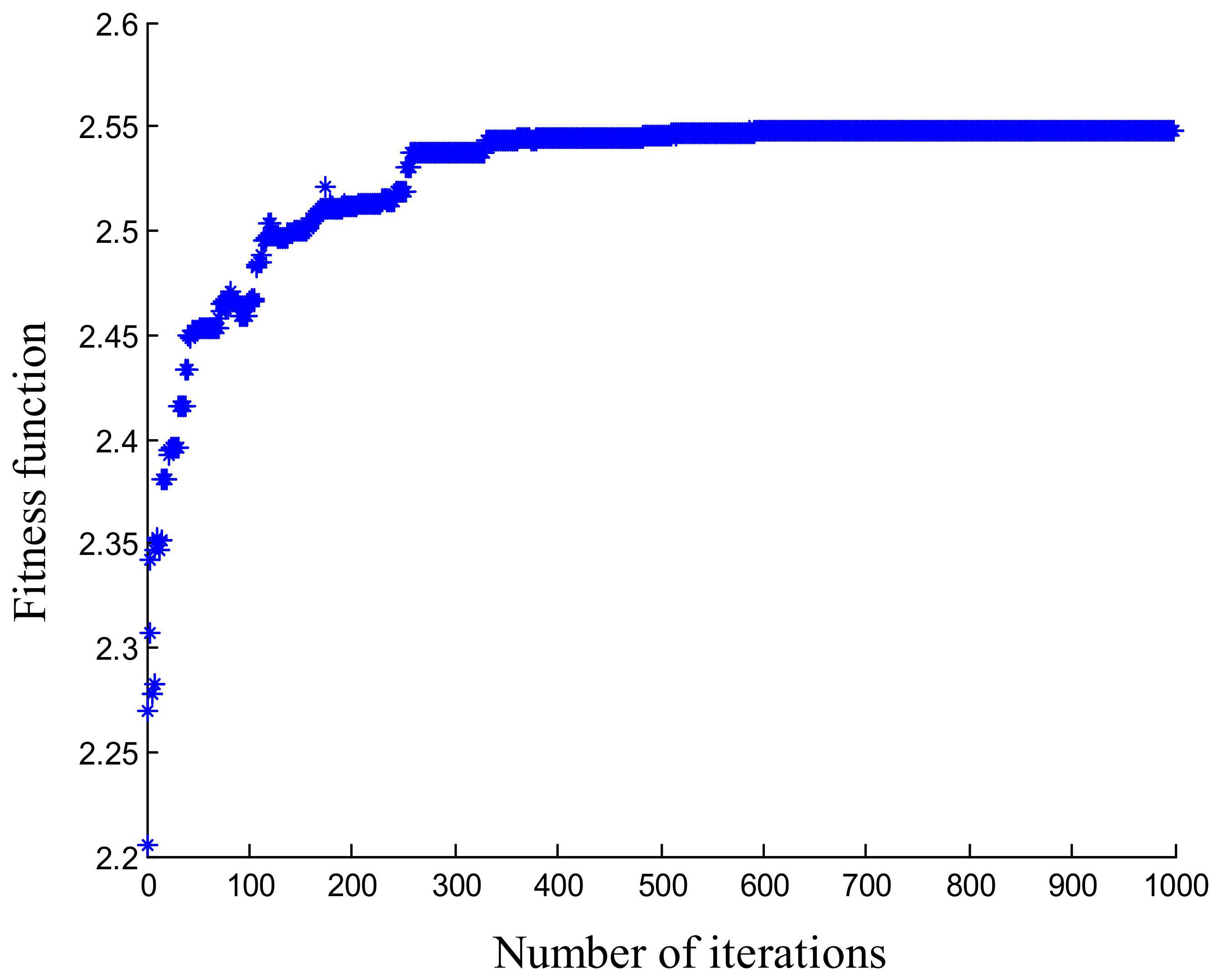
b as 5. When the population number is 100 and the mutation rate is 0.2 in the multi-objective optimization process, the execution result of the genetic algorithm is shown in
Figure 3. The search speed of the entire optimization process is high, and the final fitness function convergence value is 2.55 after 400 iterations.
The optimized results show that the maximum impact of the new shifting strategy is reduced by 15.2%, and the sliding friction power is reduced by 16%, as shown in
Table 1. However, the shifting time is prolonged by 3.5%, which proves that the shifting quality of the gearbox optimized by the genetic algorithm has been improved within the error range of 5%.
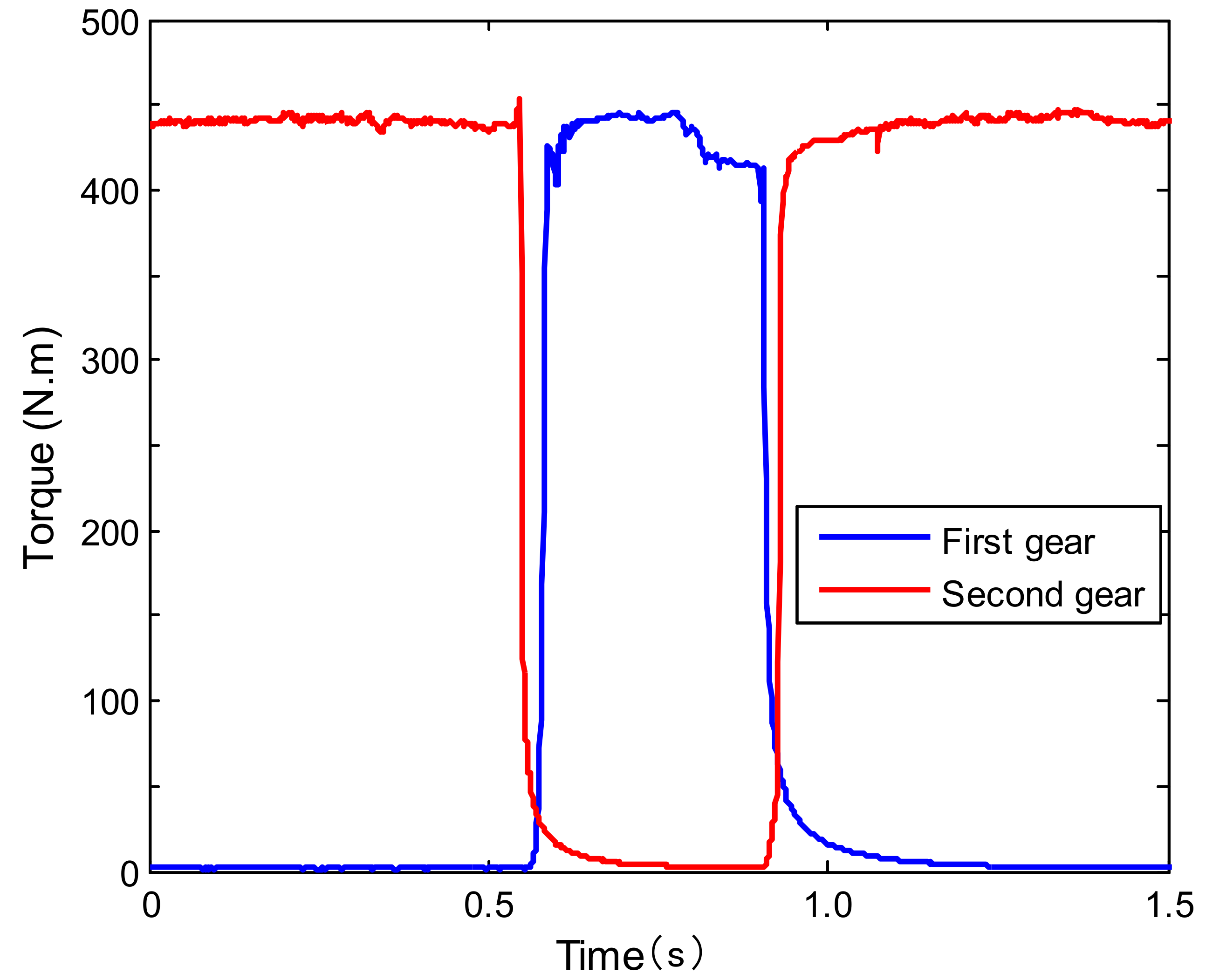
According to the optimization results, the dynamic characteristics of the transmission system are simulated, and the simulation results of clutch combination and separation in the forward gear are obtained as shown in
Figure 4. Since the input torque is determined by the load torque at the output when stable, the output torque also changes greatly when the input is abruptly changed at the moment of shifting. In turn, the friction torque of the clutch inside the transmission has changed greatly, and finally, a strong shift impact phenomenon has been generated. Since the rate of change of the driving torque determines the shifting impact, the change of the transmission torque of the clutch determines the rate of change of the driving torque, so it can be concluded that the shifting impact is determined by the transmission torque of the clutch. During the shifting process, the change control of the clutch pressure is the main one, especially the regular control of the rising pressure, which can be adjusted by the pressure buffer valve. The first shift process is the strategy before optimization, and the clutch disengagement and engagement are carried out simultaneously in the 0–0.5 s interval. Among them, the torque at 0.55 s will suddenly be zero, indicating that the friction plates of the clutch have been completely disengaged. The displacement of the clutch piston of the second gear starts to increase from the decrease of the piston displacement of the previous gear. However, when the displacement of the piston in the first stage has not been reduced to zero, the displacement of the piston in the second gear has increased, so there must be an overlapping contact state between the two. That is to say, when the gear position is not completely disengaged, the next gear has started to contact, and the coincidence time is reduced to about 0.2 s. At 0.91 s, the torque will suddenly be zero again, because the shift time is too short and there is a brief power interruption. At 1.0 s, the optimized shift strategy allows the first-speed clutch friction disc to arrive at the second-speed clutch control signal before it has completely separated, thus avoiding the appearance of shock. There was no sudden torque drop in the following shifts, and the maximum torque was also reduced, indicating that the shift impact of the gearbox was improved after the new strategy was adopted.
4. Gear Contact Strength Analysis
4.1. Load Settings and DOF Constraints
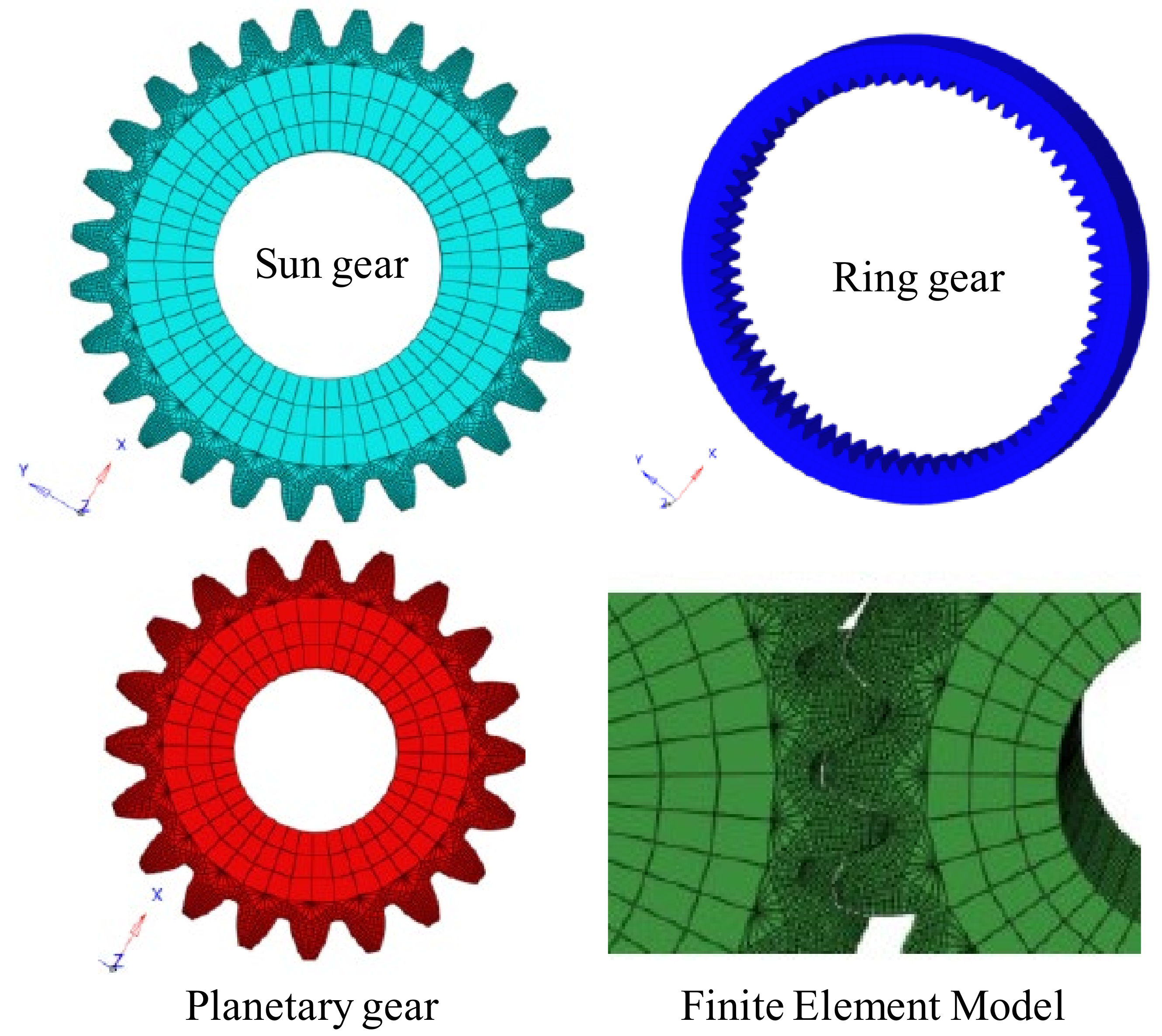
Usually, when we study the contact analysis of the gear transmission system, we mainly analyze the contact relationship between the sun gear, the planetary gear, and the ring gear. Since the planet carrier is also treated as a rigid body part in the contact analysis and does not participate in the contact analysis, it can be removed and replaced by the added kinematic connection relationship. Since the contact relationship between the planetary gear, the sun gear and the ring gear is the same, a planetary gear is selected for simplified analysis and improved computing efficiency. The simplified gear transmission system is imported into Hypermesh for mesh division, and the mesh division result is shown in
Figure 5. Import the resulting mesh file including nodes, elements, materials, related properties, and connection information into the RecurDyn software. After import, an overall rigid-soft hybrid model is established for dynamic simulation. During the contact analysis, the size of the mesh will also affect the accuracy of the results. The mesh at the contact point of the gear is subdivided, and the mesh is coarsened at the gear body and the rim. The divided sun gear finite element model has 103,573 nodes; the planetary gear model has 75,382 nodes; and the ring gear model has 263,145 nodes.
The setup steps for contact analysis are as follows:
(1) The elastic modulus is defined as 206 GPa in the material properties, and the Poisson’s ratio is 0.3;
(2) Assign material properties to the transmission system entity, establish a coupling point at the center of each gear, and add a hinge connection relationship to define the rotational relationship between the sun gear and the planetary gear;
(3) Establish the surface-to-surface contact of the ring gear, the sun gear, and the planetary gear; and assign the contact attribute. Since the time-varying meshing stiffness of the gear has been obtained in the dynamics, the mean value is selected as the definition of the contact stiffness;
(4) Establish an analysis step. In the initial analysis step, the axial displacement of the sun gear, planetary gear and ring gear is first restricted;
(5) Fixed boundary conditions are imposed on the ring gear, the sun gear only releases the degree of freedom of axial rotation, the planetary gear releases the degree of freedom of axial rotation and the translational degree of freedom of the end face. Apply a small rotation angle to the sun gear to ensure that the gap between the gear pairs is eliminated, so that the planetary gear and the sun gear, and the planetary gear and the ring gear can be in close contact;
(6) Apply the rotation angle on the sun gear, and add the load and torque to the hinge-defined shaft system. The hinge connection simulates the relationship between the planetary gear and the planetary carrier of the planetary transmission system;
(7) The contact stress and bending stress of the output gear pair are analyzed and solved.
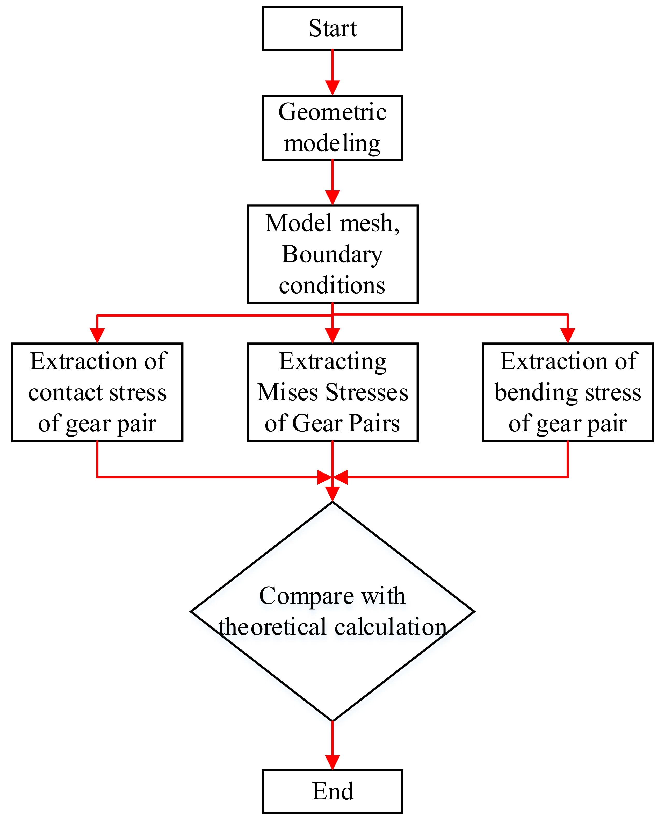
In summary, the flow chart of the entire simulation analysis and post-processing process is shown in
Figure 6.
4.2. Fatigue Stress Calculation of Gears
In the planetary gearbox, the impact of the sun gear and the planetary gear at the start and the meshing force when they are stable are the largest. Therefore, it is very important to explore the stress distribution of the sun gear from the start to the stable stage.
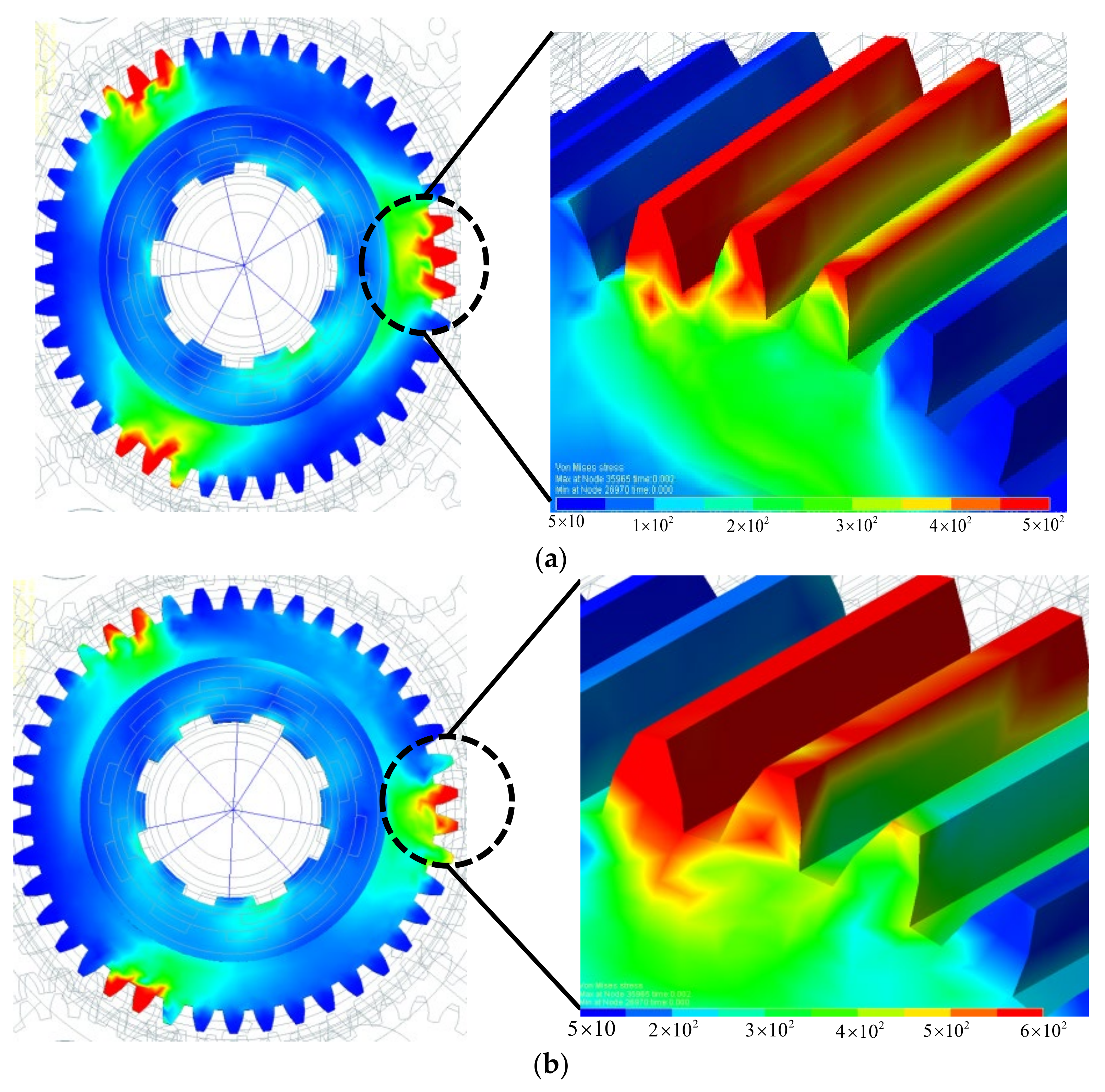
It can be seen from
Figure 7 that when starting with no load, the impact on the gear is relatively large at 0.003 s, and the stress on the gear is relatively stable after reaching the stable stage at
t = 0.006 s. The area with greater stress is at the tip of the tooth, and the stress on both sides of the tooth tip is larger than that in the middle.
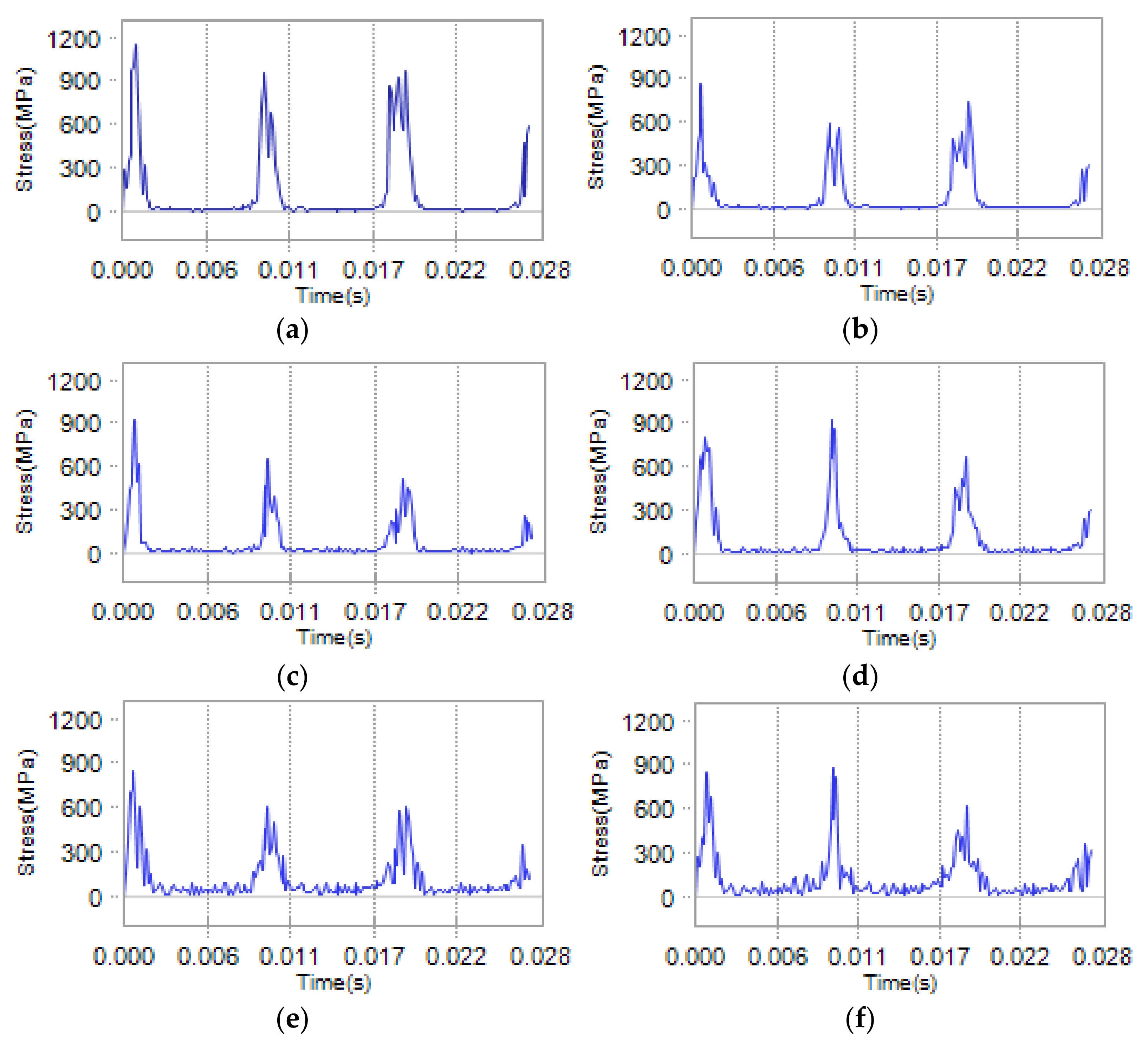
Six nodes are defined on the teeth of the sun wheel, and the points near the top, knot and root of the tooth on the tooth surface (the front side is called the A plane, the reverse side is called the B plane) are selected, and the dynamic stress–time course of the six key nodes is analyzed. It can be seen from
Figure 8 that the stress on the gear teeth changes periodically, which is consistent with the actual working conditions. The analysis shows that the maximum impact stress at the start and the average stress at stability are relatively larger. The analysis shows that the stress on surface A is relatively larger than that on surface B, and the maximum stress region is 1020 MPa at the tooth tip. According to the basic theory of mechanical design, it can be seen that the allowable stress obtained when checking the fatigue strength of the tooth surface of the sun gear is 1470 MPa. Compared with the allowable stress, it can be seen that the stress of the sun gear when starting with a full load is within a safe and reasonable range. The simulation results show that the reliability of the gear transmission system meets the requirements after the optimized shifting strategy. When operating under steady-state conditions, the sun gear is the driving gear and is in contact with the three planetary gears, so the contact fatigue of the sun gear is the most likely to fail. Since the planetary gear is in contact with the sun gear and the ring gear at the same time, it will be subjected to shearing force, so the bending fatigue life of the planetary gear is most likely to fail.
From the linear criterion, it can be seen that in high-circulatory fatigue, it is not only affected by high-level stress fatigue injury but also stress damage below the fatigue limit. Therefore, the mathematical formula for deriving the fatigue life estimated by its theory is:
where:
is the number of cycles of destruction reached on the fatigue curve;
is the relative frequency of the stress level of the ith stage;
is the level of stress at stage i; and k is the slope of the part fatigue curve.
The stress spectrum of the obtained gear pair is calculated by the linear accumulation criterion. Considering the space limitation of this paper, the list calculation is not performed here, but the fatigue life prediction results based on the linear accumulation criterion are directly listed in
Table 2.
As this method is used to calculate the fatigue life of gears, it can not only predict the most likely failure point of fatigue life but also find the specific location of gear fatigue life damage. It can be seen from the above table that when running under steady-state conditions, the sun gear is the driving gear and is in contact with the three planetary gears, so the contact fatigue of the sun gear is the most likely to fail. In the bending fatigue life, because the planetary gear is in contact with the sun gear and the ring gear at the same time, it will be subjected to shear force, so the bending fatigue life of the planetary gear is the most likely to fail. When the input speed is 900 r/min and the load is 300 N.m, the minimum contact fatigue life of the sun gear is 1.42 × 105.3, and the bending fatigue life is also the minimum of 1.61 × 106.8.
5. Shift Test
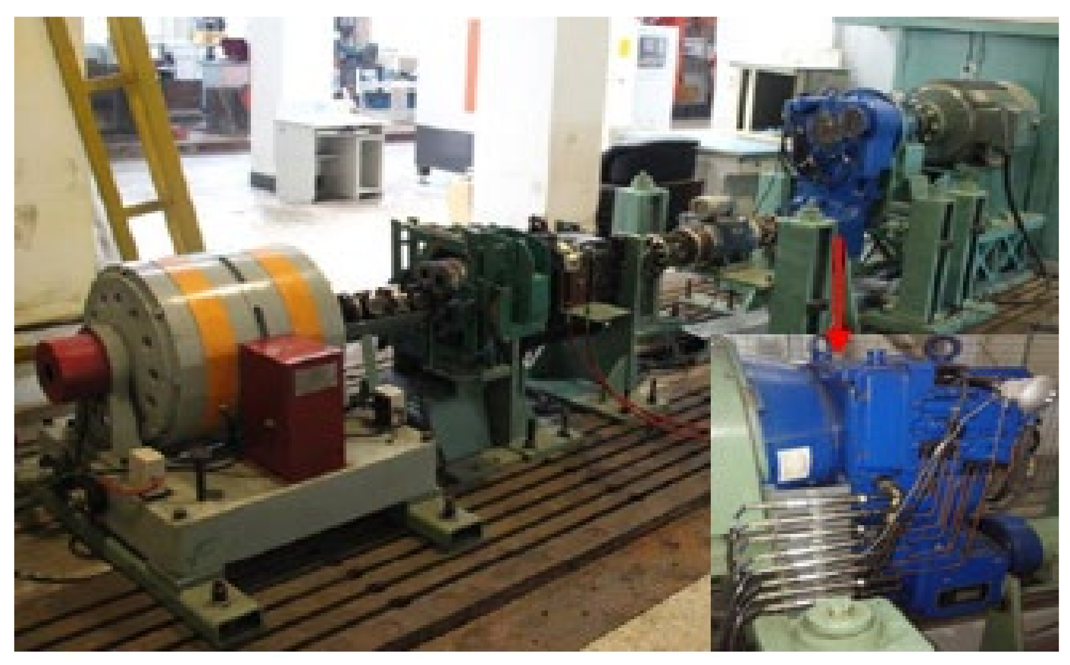
After the simulation analysis of the transmission system, it is necessary to verify the reliability of the shifting quality of the transmission system. In order to verify the correctness of the shifting quality optimization process and analyze the vibration during shifting, the transmission was tested according to industry standards. The speed and torque of the output shaft in each gear are collected on the test bench, and the gear shifting sliding friction work is calculated according to the gear transmission ratio and the shifting transmission route. It is impossible to test the shift impact of the whole machine on the test bench. It is necessary to use the dynamic signal test and analysis system to conduct a vibration test on the transmission case, and then indirectly analyze the vibration impact of the transmission during the shifting process. The acceleration sensor is placed vertically in the vertical direction of the transmission case, and the vibration curve during the shifting process is collected in cooperation with the dynamic signal test and analysis system. Since there are many interference signals in the shifting process, it is necessary to filter the collected vibration acceleration of the box. By performing spectrum analysis and band-pass filtering on the collected vibration signal, the shifting vibration waveform can be obtained, as shown in
Figure 9. The test bench consists of a drive motor, a load motor, two auxiliary test gearboxes, an elastic coupling and a universal coupling. The drive motor is connected to the input end of the test gearbox through the accompanying test gearbox, and the load motor is connected to the output end of the test gearbox through the accompanying test gearbox. By adjusting the speed of the drive motor and the torque and speed of the load motor, the vibration test of the gear set during stable operation is realized.
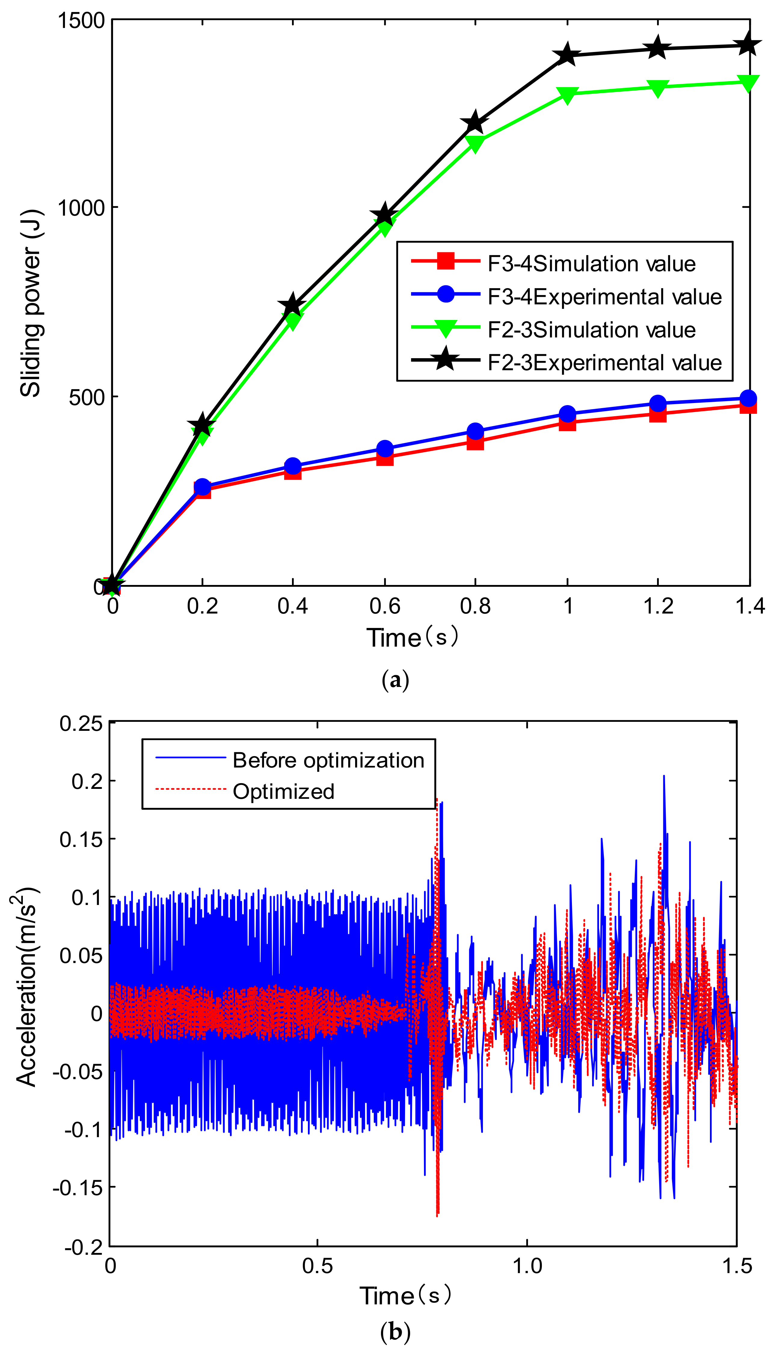
When the second gear is changed to the third gear and the fourth gear is changed to the fifth gear, the sliding friction work generated by the two clutches is 1410 J and 1435 J, respectively, as shown in
Figure 10a. When the neutral gear is changed to the first gear, since the transmission does not transmit power before shifting, the friction work does not generate when the clutch is engaged. Compared with the simulation value, it is found that the error is small, which verifies the correctness and reliability of the shifting quality simulation, and provides a test basis for further improving the shifting quality. Through the vibration test results in
Figure 10b, it is found that the optimized front clutch combination vibrates relatively violently during the forward process, and the shock is relatively large during the shifting process. After the optimization, the shift shock is reduced and there is no instantaneous power interruption phenomenon. Therefore, the optimal shift control improves the dynamic performance of the transmission system. Compared with the total acceleration vibration level of the gearbox before optimization, the acceleration total vibration level of the gearbox measuring points after the optimization measures are all decreased, and the reduction range is about 10 dB. It shows that the measures of gear modification and hydraulic system optimization can effectively improve the overall vibration performance of the gearbox.
Table 3 shows the average value of rotational speed and torque of each component (where the negative sign indicates the opposite direction) and the transmission efficiency. The input shaft power is input by the planet carrier of the planet row, and output from the sun gear and ring gear of the planet row, respectively. Its output kinematic transmission ratio is 3.14 and its dynamic transmission ratio is 3.0. The power through the sun gear accounts for 21%, and this part of the power is output by the output shaft. The power through the ring gear accounts for 79%, and the transmission efficiency of the planetary row can be calculated to be 94.8%.
6. Conclusions
The dynamic analysis of the gear shifting work of the gearbox is carried out, and the main factors affecting the shifting instability of the gearbox are studied. Taking impact degree and sliding friction energy as optimization goals, the gear shift quality is optimized based on a multi-objective genetic algorithm. Furthermore, through the bench test, the vibration test of the gearbox after the optimization measures is carried out is verified. The flexible body model of key gears is established, the gear meshing force and sun gear stress distribution under different working conditions, and the vibration spectrum analysis of key nodes of the sun gear are analyzed, which lays the foundation for the fatigue strength and life prediction of the gear system. The conclusions are summarized as follows:
(1) Based on the multi-objective genetic algorithm, the gear shift quality is studied, and the effects of population quantity and variable rate on the optimization results are obtained. The shift shock of the clutch is reduced during the optimized rear gear shifting process, and the power interruption phenomenon has also been improved. Experiments show that the multi-objective optimization results improve the shifting comfort and improve the dynamic performance of the gearbox.
(2) Under the same gear, the meshing force of the second planetary row gear in each planetary row is the largest. The stress of the node near the tooth tip is larger than that of the pitch circle and the node near the root of the tooth, and the stress on both sides of the tooth tip is relatively larger than that in the middle.
(3) The vibration test analysis results before and after the optimization of the shifting strategy show that the hydraulic vibration harmonics on the frequency spectrum of the gearbox disappear, and the total vibration level decreases by about 10 dB.
(4) During the dynamic contact process, the sun gear is the driving gear and is in contact with the three planetary gears, so the contact fatigue life of the sun gear is the smallest. As the planetary gear is in contact with the sun gear and the ring gear at the same time during the contact process, it will be subjected to a certain shear stress, so the bending fatigue life of the planetary gear is the smallest.
The outlook for future work is as follows:
(1) When modeling the virtual prototype, the dynamic characteristics of the bearings in the gearbox under various working conditions, the performance impact of the bearing lubrication state and the lubrication characteristics can be considered to make the connection between the input and output shafts of the gearbox and the box more realistic.
(2) When establishing a rigid-flexible hybrid model, structures such as the flexible ring gear, planet carrier and planet carrier can be regarded as flexible bodies. The dynamic characteristics of multiple flexible bodies are studied, and the strength of the key components of the gearbox is checked to provide a certain basis for studying the structural strength of the gearbox.


