Article

Research on Dynamic Characteristics of Canopy and Column of Hydraulic Support under Impact Load

1
College of Mechanical and Electronic Engineering, Shandong University of Science and Technology, Qingdao 266590, China
2
College of Information Science and Engineering, Shandong Normal University, Jinan 250358, China
*
Author to whom correspondence should be addressed.
Energies 2022, 15(13), 4638; https://doi.org/10.3390/en15134638
Submission received: 9 June 2022 / Revised: 16 June 2022 / Accepted: 23 June 2022 / Published: 24 June 2022

Abstract

:
In the process of coal mining, the canopy and column play an important role in the safety support of hydraulic support. However, due to the complex and changeable coal seam conditions, the hydraulic support is significantly affected by the impact load. This paper aims to reveal the dynamic characteristics of canopy and column under impact load. Firstly, the dynamic model of hydraulic support is established, and the impact response of each hinge point of the canopy is analyzed. Secondly, based on the fluid–structure interaction (FSI) theory, the two-way FSI model of the column is established, and the structural change of the column and the flow field characteristics in the cylinder under the impact load are analyzed. The results show that the front column hinge is more prone to impact failure under impact load. The impact load has a significant impact on the two-level cylinder, the pressure in the cylinder increases, and an eddy current occurs on both sides of the bottom of the cylinder. The research results can provide references for the structural optimization of the hydraulic support with anti-impact load and the strength design of the column.

Graphical Abstract

1. Introduction

Hydraulic support is important supporting equipment of a fully mechanized working face, which can support and manage the roof and maintain a safe working space. The canopy is the component directly contacting the roof in the hydraulic support, which is responsible for carrying and transferring the roof load and plays a key role in the stable operation of the whole support [1,2,3,4]. With the advancement of the working face, various geological conditions and complex mining environments under the mine have strict requirements for the canopy directly loaded. When the basic roof breaks or gangue falls, the canopy will be affected by the impact load, resulting in the canopy being overloaded or unevenly loaded. In this case, the pin shaft at the canopy hinge often deforms, wears, and even breaks to varying degrees [5,6,7], which has a serious impact on the stable support of hydraulic support and underground safety operation.
Scholars have carried out many studies on the response law of hydraulic support under impact load. Wang et al. [8] studied the impact dynamic load adaptability of hydraulic support when impact load acted on canopy and caving beam by numerical simulation, and summarized the adaptability of hydraulic support under different impact loads. Ren et al. [9] proposed a monitoring scheme for the dynamic response of hydraulic support, carried out multi-scale impact tests on hydraulic support, and verified the test data and simulation data by combining them with numerical simulation; the results showed that the impact resistance of hydraulic support depended largely on the initial support condition. Szurgacz et al. [10] carried out impact tests on hydraulic supports and pointed out the possible dangerous areas in hydraulic supports. Li et al. [11] studied the mechanical properties and stiffness characteristics of the hydraulic support group under different working conditions through the combination of theoretical analysis and numerical simulation, which provided references for the optimization design of hydraulic support. Based on the dynamic model of super large mining height hydraulic support, Yang et al. [12] analyzed the impact characteristics of super large mining height hydraulic support and summarized the overall influence of impact load on the stress state of hydraulic support. Zeng et al. [13] analyzed the coupling relationship between hydraulic support and surrounding rock, equated the column to a variable stiffness damping system, and analyzed the impact response of each hinge point of the support under different impact loads. Liang et al. [14] studied the force transfer characteristics of hydraulic support under impact load and summarized the influence of different action positions on the force transfer characteristics and sensitivity of each hinge point.
However, in the above analysis of the impact dynamic load characteristics of hydraulic support, the stress of the column structure and its internal flow field distribution are ignored. The effect caused by the change of flow field has attracted the attention of scholars in other fields. Liu et al. [15] established the fluid–structure interaction model of offshore wind turbine and sea ice, and studied the dynamic response and deformation of offshore wind turbine structures under the coupling effect. Based on the fluid–structure interaction theory, Liang et al. [16] analyzed the structural characteristics of the pipeline system and expounded the dynamic change law of pipeline vibration caused by gas–liquid two-phase flow. Wang et al. [17] established the fluid–structure interaction model of the reciprocating compressor with reed valve and studied the dynamic characteristics of reed valve and the flow characteristics of the reciprocating compressor. Guo et al. [18] discussed the mechanism of friction, Poisson, and connection coupling, established the fluid–structure interaction model of the pipeline system, and revealed the dynamic characteristics of the pipeline system under different supports. Guo et al. [19] analyzed the flow field characteristics of the asymmetric hydraulic cylinder during start-up by combining numerical simulation with experiment and obtained the pressure distribution and velocity distribution of asymmetric hydraulic cylinder flow field during start-up. Qu et al. [20] established the two-way fluid–structure interaction model of the hydraulic pipe and studied the dynamic characteristics of the hydraulic pipe under different supporting stiffness conditions by combining numerical simulation with experiment, which provided references for the structural design of the hydraulic pipe. These studies take into account the effects of fluid changes.
Since the impact resistance of the hydraulic support column is one of the key factors affecting the safe mining of the working face, scholars have carried out relevant research on the dynamic characteristics of the column under impact load. Szurgacz et al. [21,22] conducted impact tests on the column, analyzed the variation trend of liquid pressure in the cylinder under different impact states, and summarized the dynamic characteristics of the column under impact load. Based on the hammer method and the equivalent stiffness theory of the column, Xu et al. [23] calculated the maximum pressure of the liquid in the cylinder under the hammer impact and obtained the maximum load point of the column by simulation analysis, which provided references for the strength design of the column. Sui et al. [24] based on the fluid–structure interaction theory, compared the stress distribution of the cylinder under the static pressure and the oil, and summarized the influence of oil on the cylinder. Liu et al. [25] studied the dynamic characteristics of the column under impact load based on the FEM and SPH methods, which provided references for the development of the column impact resistance test device.
At present, impact condition is a common condition in the working process of the hydraulic support. Scholars have carried out a lot of research on the response characteristics of hydraulic support under impact conditions and the impact resistance of columns. However, due to the complex and changeable coal seam conditions, the impact load on the canopy is random and irregular. Although the impact response of the hinge point is considered in the above research, there are few studies on the influence of the impact position of the canopy load on the canopy hinge point. Moreover, when studying the impact resistance of the column, the impact position of the canopy load on the flow field characteristics of the column is ignored, which is difficult to fully reveal the response characteristics of the hydraulic support under the impact load. Therefore, based on the previous theories and methods of dynamic load analysis of hydraulic support, to further explore the adaptability of the canopy under impact load, the impact dynamic model of hydraulic support is established in LS-DYNA, and the impact response of each hinge point of the canopy under impact load is analyzed. The improvement suggestions of each hinge point for the canopy are put forward, which is of great significance to improve the impact adaptability of the canopy. On this basis, to analyze the structural change of the column and the flow field characteristics in the cylinder, based on the fluid–structure interaction theory, the two-way fluid–structure interaction model of the column is established in FLUENT, and the dynamic characteristics of the column under the impact load are studied, which provides references for the structural design of the column.

2. Dynamic Characteristics of Canopy under Impact Load

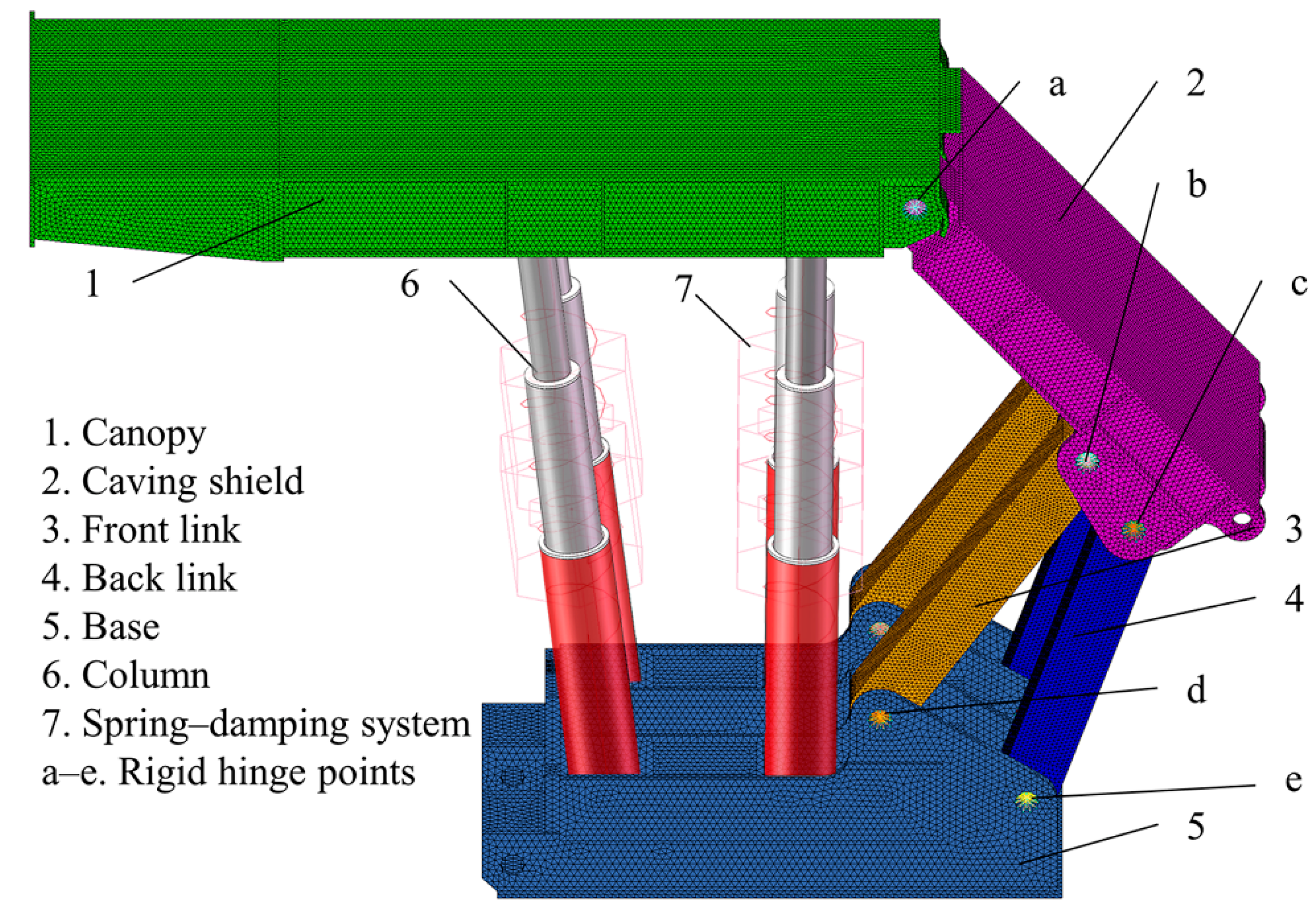
2.1. Dynamic Model of Hydraulic Support

The top coal caving hydraulic support is composed of the canopy, caving shield, tail beam, and base. ZF22000-29-55 top coal caving hydraulic support is selected for analysis in this paper. Its working resistance is 22,000 KN and the maximum working height is 5.5 m. The dynamic model of hydraulic support is established as shown in Figure 1. The working height of the hydraulic support is 5.5 m. Before the periodic fracture of the main roof, the hydraulic support is in a stable working state and the static load is 8000 KN. To simulate the impact load on the canopy, the point load is directly applied to the canopy, and the impact load is 1000 KN. The non-main bearing parts such as the side panel are ignored in the model. To shorten the simulation time and improve the calculation efficiency, the small structures such as round angle and chamfer are simplified and the coal caving mechanism is ignored. In pre-processing, the tetrahedron elements are used to complete the finite element mesh generation in the software of HyperMesh. The rigid node area is established at the hinged shaft hole of each component, the rotational pair connection is defined to facilitate the transfer of force, and the column is assumed as a spring damping system.
The simulation parameters of the model are set in LS-PREPOST. The components of hydraulic support are mainly welded by steel plates. The material model of the steel plate is the PIECEWISE_LINEAR_PLASTICITY model, and the material parameters are shown in Table 1. The node-set at the bottom layer of the base is set as the node-set, and the SPC_SET is used to impose full constraints on the node-set. The simulation time is set as 0.6 s and the simulation output step size is set as 0.002 s. After setting the boundary conditions, the finite element solution is completed by calling the K file through ANSYS/LS-DYNA solver.

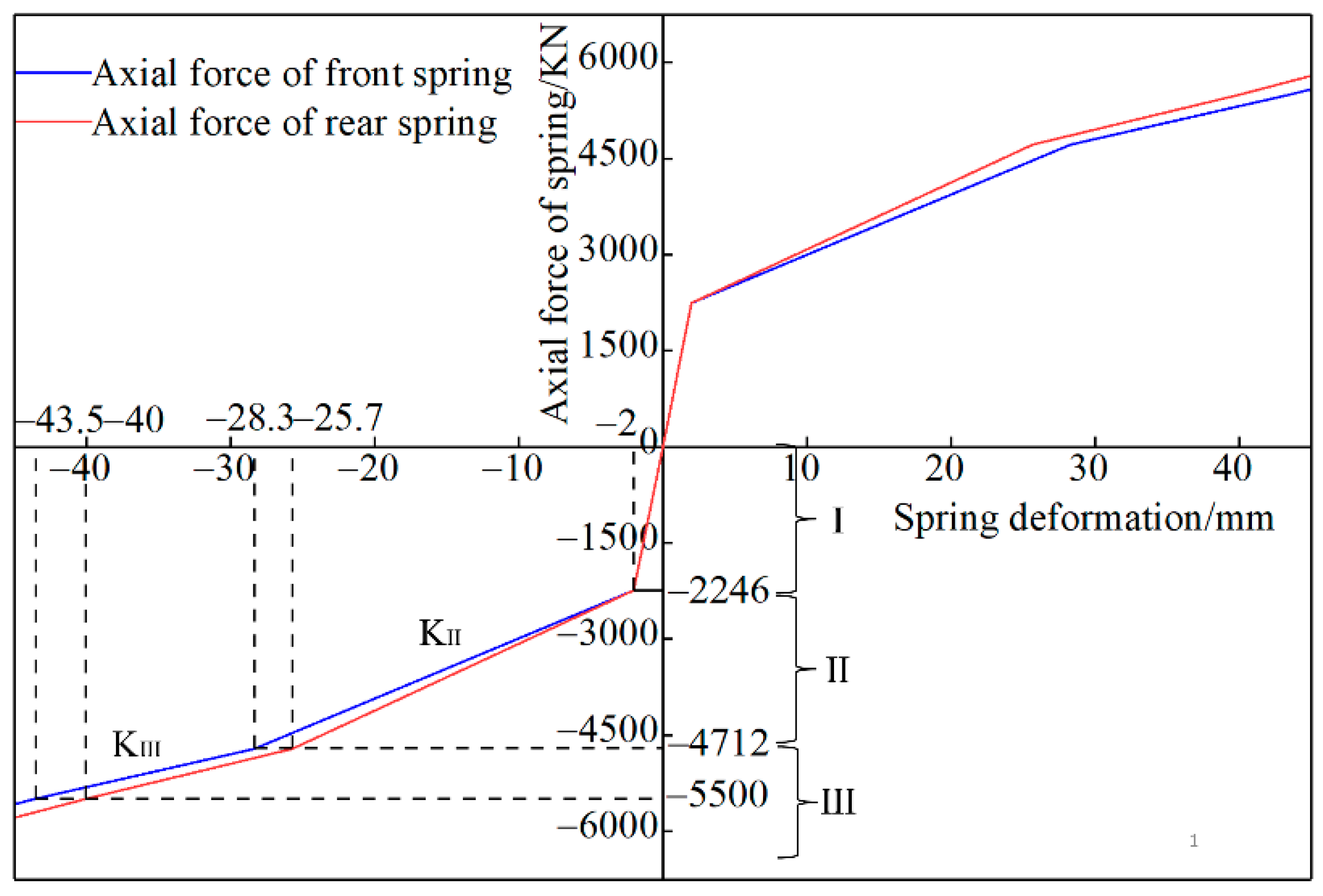
2.2. Spring Damping Stiffness Model of Column

In the process of supporting hydraulic support, the column will be affected by an external force, so that the emulsion in the cylinder is compressed. Therefore, the column shows elastic characteristics. As shown in Figure 2, the column is equivalent to the spring damping model. Among them, the spring model adopts the SPRING_NONLINEAR_ELASTIC model, and the damping adopts the DAMPER_VISCOUS model.
When the column extends, the cylinder is filled with high pressure emulsion. With the increase of external force, the bearing characteristics are mainly manifested in three stages. The first stage is the support setting stage. The external force on the column is less than the initial pressure in the cylinder. The one-level cylinder and the two-level cylinder are not compressed, and the equivalent stiffness of the column is infinite. The second stage is the passive support stage of the support. The external force on the column exceeds the initial pressure of the two-level cylinder. The two-level cylinder begins to be compressed and the one-level cylinder remains unchanged. At this time, the equivalent stiffness of the column is the stiffness of the two-level cylinder k2c. The third stage is the rapid pressurization stage of the bracket. The external force of the column exceeds the initial pressure of the one-level cylinder, and the one-level cylinder and the two-level cylinder are compressed. At this time, the equivalent stiffness kc of the column is the series connection of the one-level cylinder stiffness k1c and the two-level cylinder stiffness k2c. Under the action of external force, the cylinders at all levels and emulsions are in the state of solid–liquid coupling [26,27]. The stiffness k1c of the one-level cylinder and the stiffness k2c of the two-level cylinder can be defined as Equation (1):
k i c = k i s × k i w k i s + k i w
where kic is the equivalent stiffness of the i stage cylinder, kis the equivalent stiffness of the i stage cylinder block, kiw is the equivalent stiffness of the i stage cylinder emulsion.
The bulk modulus of liquid can be defined as Equation (2):
E w = Δ P × A × L w A × Δ L w
where Ew is the bulk modulus of emulsion, Lw is the length of liquid column in the cylinder, ΔLw is the compression amount of liquid column in the cylinder, ΔP is the variation of cylinder pressure, A is the cross-sectional area of the liquid column in the cylinder.
By Equation (2), the equivalent emulsion stiffness kiw of the i stage cylinder can be defined as Equation (3):
k i w = A i × E w L i w
where kiw is the equivalent stiffness of the i stage cylinder emulsion, Ai is the cross-sectional area of the liquid column in the i stage cylinder, and Liw is the length of the liquid column in the i stage cylinder.
The elastic deformation of the cylinder is caused by internal pressure. According to the thick-walled cylinder deformation theory [28,29], the radial deformation Δd of the cylinder with the internal pressure P and the external pressure 0 can be defined as Equation (4):
Δ d = d × P × 1 v × d 2 + 1 + v × D 2 2 E s × D 2 d 2
where Δd is the radial deformation of the cylinder, P is the cylinder internal pressure, d is the internal diameter of the cylinder, D is the external diameter of the cylinder, v is the Poisson’s ratio, Es is the elastic modulus of the cylinder.
Volume elastic modulus of the cylinder can be defined as Equation (5):
E k = Δ P × V Δ V
where Ek is the volume elastic modulus of the cylinder, ΔP is the cylinder internal pressure variation, ΔV is the cylinder volume change, V is the initial volume of the cylinder.
The ratio of the volume change ΔV of the cylinder to the initial volume V of the cylinder can be defined as Equation (6):
Δ V V = 4 × Δ d 2 + d × Δ d d 2
Because Δd is far less than d. By combining (5) and (6), the volume elastic modulus of the cylinder can be defined as Equation (7):
E k = Δ P × d 4 × Δ d
By Equation (7), the equivalent stiffness kis of the i stage cylinder block can be defined as Equation (8):
k i s = E i k × A i
By combining (1)–(8), the equivalent stiffness kic of the i stage cylinder can be defined as Equation (9):
k i c = A i × E w × E s × D i 2 d i 2 2 E w × 1 v × d i 2 + 1 + v × D i 2 + E s × L i w × D i 2 d i 2
Taking the hydraulic support at the highest working height as an example, the material type of the column is 27SiMn, and the emulsion is selected for the liquid in the cylinder. The size parameters of the column are shown in Table 2. The equivalent stiffness of the front and rear columns at different stages is obtained by Equation (9), as shown in Table 3.
Because the SPRING_NONLINEAR_ELASTIC model is used in the spring damping system, the axial force-deformation curve of the spring is established by using the equivalent stiffness of different stages in Table 3, as shown in Figure 3.
The equivalent spring has two stress states of compression and tension. As shown in Figure 3, the bearing stage of the column is divided into three stages: I, II, and III, and each stage represents different equivalent stiffness. Here, it is set that the spring is compressed according to the approximate linear stiffness in each stage. In stage I, since the external force has not yet reached the initial pressure of the two-level cylinder, the length of the spring should not be changed, but the spring appears 2 mm compression in the figure, which is due to the initial fluctuation of the spring. When the axial force increases to 2246 KN, the spring is in stage II and begins to retract with stiffness KII. With the compression of the front spring to 28.3 mm, the axial force increases to 4712 KN, the one-level cylinder and the two-level cylinder are compressed at the same time, and the stiffness KIII of the spring decreases significantly. The front spring compression is 43.5 mm, and the axial force is increased to 5500 KN, that is, the front column reaches the rated working resistance. Because the length of the liquid column of the front column and the rear column is different, there is a certain difference between the front spring and the rear spring in the stiffness change of the whole stage.

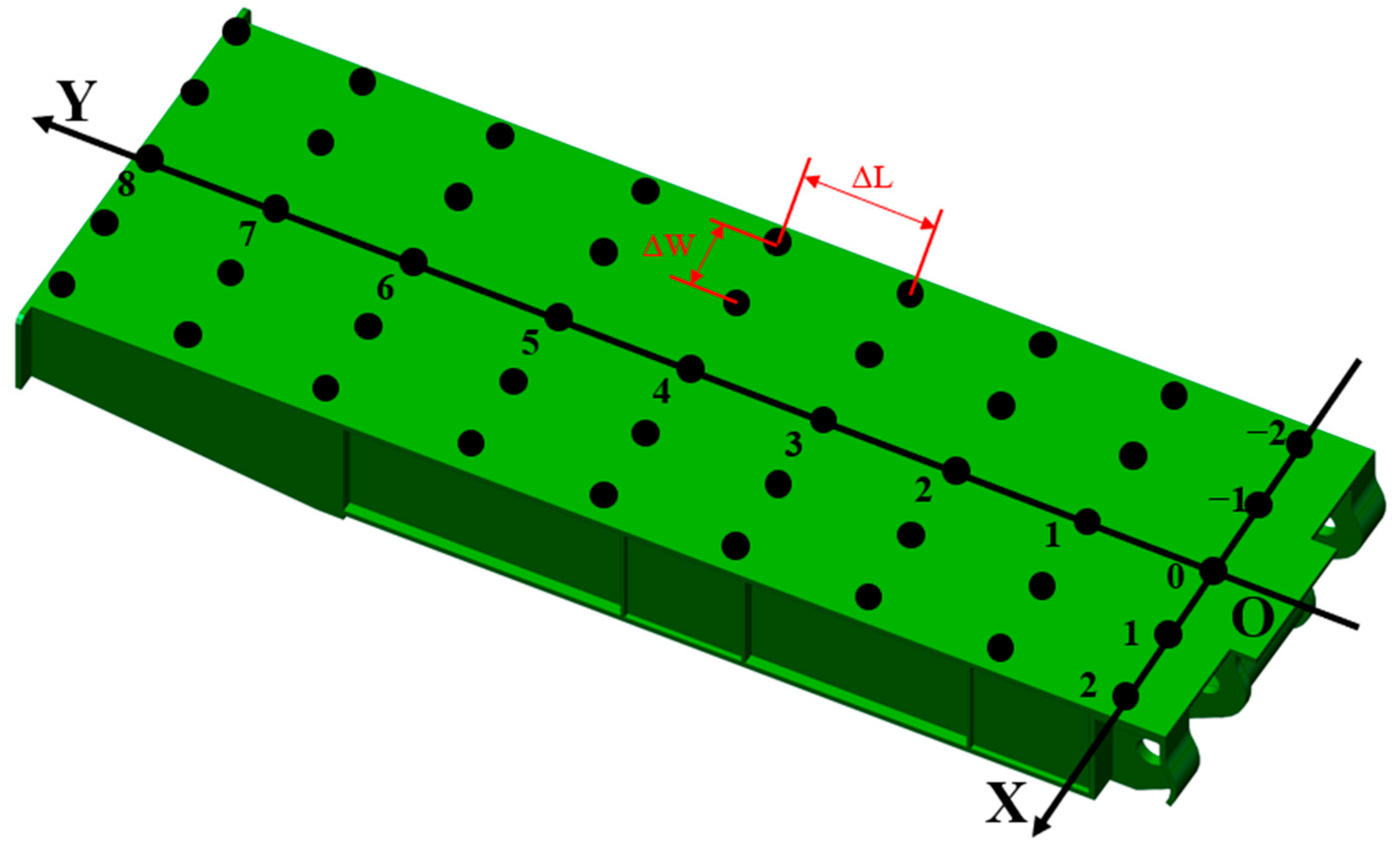
2.3. Definition of Impact Load

In practice, the contact between canopy and roof is usually random and irregular. When the main roof has periodic fractures, the canopy will also be subjected to impact load based on the original load, which is easy to cause the wear of the hinge hole and even the fracture of the pin shaft. To analyze the impact response of the canopy load impact position to the hinge point, a total of 45 impact load points are selected. As shown in Figure 4, the X-axis direction represents the width direction of the canopy, and the interval ΔW = 420 mm from (−2, Y) to (2, Y). The Y-axis direction represents the length direction of the canopy, and the interval ΔL = 420 mm from (X, 0) to (X, 8). The origin O is on the central surface of the canopy.
Before the periodic fracture of the main roof, the hydraulic support is in a stable working state. Therefore, when the canopy is subjected to impact load, its force can be divided into two parts. The first part is the normal bearing roof pressure, and the second part is the impact load caused by the main roof fracture. To simulate the impact response of the hinge point when the canopy is impacted, the normal bearing roof pressure is 8000 KN on the canopy, the impact load is applied after stability, and the impact load duration is 0.05 s.

3. Impact Response of the Hinge Point of the Canopy

3.1. Impact Response of the Hinge Point between the Canopy and the Column

According to the above impact load acting on different positions of the canopy, the simulation under various working conditions is completed in turn to obtain the impact response of the hinge point of the canopy. It can be seen from Figure 4 that the two sides of the canopy are completely symmetrical in the X-axis direction, so to improve the research efficiency, only the hinge points on the positive side of the X-axis are analyzed. Because when the impact load acts on different positions, the impact response of each hinge point is different. To compare the results at the same scale, the impact response coefficient μ is introduced for scale transformation [13]. The impact response coefficient μ can be defined as Equation (10):
μ X ,   Y = F I m a x × F S m a x F I
where μ(X, Y) is the impact response coefficient of the hinge point when the impact load acts on the canopy (X, Y) position, FImax is the peak response force of the hinge point under impact load, FSmax is the peak response force of the hinge point of the canopy under normal load state, FI is impact force.
When the impact load acts on different positions of the canopy, the impact response of the hinge point between the canopy and the column is shown in Figure 5. Selecting μ = 0.1 and μ = 0.2, the impact response coefficient μ of the hinge point of the column is divided into three sections. In section I, μ ∈ (min, 0.1) is defined as a stationary response area. In section II, μ ∈ (0.1, 0.2) is defined as a transition response region. In section III, μ ∈ (0.2, max) is defined as a wave response region.
It can be seen from Figure 5a that when the impact load moves along the positive direction of the X-axis, the impact response coefficient of the hinge point of the front column shows an increasing trend, and the column will have obvious the eccentric load effect. The analysis of reference [8] also supports this result. The closer to the origin direction, the smaller the eccentric load effect of the column is. This is because there are two front columns in the X direction, and the different positions of the impact load will cause different impact responses to the front columns on each side, resulting in the eccentric load effect of the column. At the same time, the impact amplitude of the column on the opposite side of the impact load will decrease due to the influence of the bending moment. Therefore, the closer the impact load is to one side of the front column, the compression of the front column will increase. When the impact load moves along the positive direction of the Y-axis, the impact response coefficient of the hinge point of the front column shows an increasing trend, and the change of the impact response coefficient covers three sections. In (−2, Y), the front column action line divides section I and section II, and in (2, 8), the impact response coefficient of the front column hinge point reaches the maximum. This is because the canopy is divided into three regions by the column hinge point. When the impact load acts on the back end of the canopy, the bending moment effect of the impact load on the front column hinge point will be weakened due to the support effect of the rear column. However, as the impact load crosses the action line of the front column, the stress state of the canopy is similar to that of the cantilever beam. The longer the force arm is, the greater the bending moment generated at the hinge point of the front column is, increasing in the impact response of the hinge point of the front column. Therefore, when the impact load is close to the front end of the canopy, the impact adaptability of the front column is continuously reduced, and the load condition is more serious.
It can be seen from Figure 5b that the changing trend of the impact response of the hinge point of the rear column is similar to that of the front column. When the impact load moves along the positive direction of the X-axis, the column will have obvious the eccentric load effect. When the impact load moves along the positive direction of the Y-axis, the impact response coefficient of the hinge point of the rear column shows an increasing trend. However, the impact response coefficients of the hinge point of the rear column are only in section I and section II, and there is only impact load acting on the front of the canopy in section II. This is because the supporting effect of the front column reduces the influence of the impact load on the bending moment of the hinge point of the rear column, resulting in the weakening of the impact response of the hinge point of the rear column. Therefore, the rear column has good impact adaptability.
According to the above analysis, the front column and the rear column have obvious differences in the impact response to the impact load at different locations. When the impact load moves along the positive direction of the Y-axis, the impact response coefficients of the front column and the rear column hinge points show an increasing trend, and the impact response of the front column hinge point is more intense. When the impact load moves along the positive direction of the X-axis, the impact response coefficient of the hinge point of the column also shows an increasing trend, and the column will have an obvious the eccentric load effect. The closer to the origin direction, the eccentric load effect of the column will continue to decrease.
When the canopy is subjected to the impact load, due to the different impact response of the hinge point of the front column and the rear column, the support state of the front column and rear column to the canopy also changes, resulting in the change of the attitude of the canopy. Therefore, to analyze the influence of the impact load on the attitude of the canopy, the displacement fluctuations of the column hinge points in the vertical direction are compared, as shown in Figure 6.
It can be seen from Figure 6 that the displacement fluctuation trend of the column hinge points is similar to that of their impact response coefficient. When the impact load moves along the positive direction of the X-axis or the Y-axis, the displacement fluctuation amplitude of the column hinge points increases gradually. The displacement fluctuation amplitude of the front column hinge point is larger, and the displacement fluctuation trend of the rear column hinge point is gentle. This is because the impact responses of the front and rear column hinge points are different, and the impact response of the front column hinge point is more intense. Therefore, under the impact load, the canopy will show a low-head attitude, and as the impact load moves to the front of the canopy, the phenomenon of the canopy’s being low-head is increasing.
It can be seen from Figure 5 that when the impact load acts at position (2, 8), the impact response coefficient of the column hinge point is the largest, so the peak response force of the impact load at the column hinge point is the largest. To observe the impact more intuitively on the column hinged holes, the stress distribution of the column hinged holes is compared when the canopy is under normal load and the impact load acts at position (2, 8), as shown in Figure 7, where the stress is von Mises stress and the unit is Pa.
It can be seen from Figure 7 that the stress distribution of the front and rear column hinged holes is different, and the stress of the front column hinged holes is significantly higher than that of the rear column hinged holes. When the canopy is subjected to the impact load, the stress of the front column hinged holes increases, and it is prone to stress concentration above the hinged holes near the front side of the canopy, and its stress value is close to the yield strength. Combined with the analysis of the column hinged holes stress and reference [6], this is because when the impact load acts at the (2, 8) position, the bending moment generated by the impact load on the hinge point of the front column is the largest, and the extrusion pressure on the hinge holes of the front column is large. Therefore, the hinged holes of the front column should be strengthened when necessary. For the hinged holes of the rear column, the stress variation caused by the impact load is relatively low.

3.2. Impact Response of the Hinge Point between the Canopy and the Caving Shield

For the four-column hydraulic support, in addition to the column hinge point in the canopy, another key hinge point is the caving shield hinge point. Therefore, to comprehensively analyze the impact response of different positions of the impact load to the hinge point of the canopy, the impact response coefficient of the hinge point of the caving shield is calculated by using Equation (10), as shown in Figure 8.
It can be seen from Figure 8 that when the impact load moves along the positive direction of the X-axis, the impact response coefficient of the hinge point of the caving shield shows a decreasing trend, and the hinge point shows the partial load effect. Especially when the impact load moves near the action line of the rear column, the partial load effect is more obvious. This is because the hinge points of the caving shield are symmetrically distributed on both sides of the canopy. Different impact load positions will cause different impact responses to the hinge points of the caving shield on each side, resulting in the partial load effect of the hinge points. When the impact load moves along the positive direction of the Y-axis, the impact response coefficient of the hinge point of the caving shield shows an increasing trend. When the impact load acts at (2, 0), the impact response coefficient of the hinge point of the caving shield is the smallest, about −0.99. When the impact load acts at (−2, 8), the impact response coefficient of the hinge point of the caving shield is the largest, about 1.17, and the impact response coefficient presents a hierarchical distribution along the diagonal direction of the canopy. This is because the impact load will produce a bending moment on the hinge point of the caving shield. As the distance between the impact load position and the hinge point of the caving shield increases, the bending moment also gradually increases, increasing in the impact response of the hinge point of the caving shield. Therefore, when the impact load acts at the front end of the canopy, the impact response of the hinge point of the caving shield is more intense, and the pin shaft may fail at this time. When the impact load acts at the back end of the canopy, the impact response of the hinge point of the caving shield is weak, and the load of the pin bearing load is small, but the hinge point of the caving shield will show partial load effect.
According to the changing trend of the impact response coefficient, (−1, Y), (1, Y), the front column action line and the rear column action line are selected to form the boundary of the O region. In the O region, the impact response coefficient of the hinge point of the caving shield is close to 0. Therefore, when the impact load is in the O region, the impact adaptability of the hinge point of the caving shield is better, and the safety of the pin shaft is better.

4. Dynamic Characteristics of the Column under Impact Load

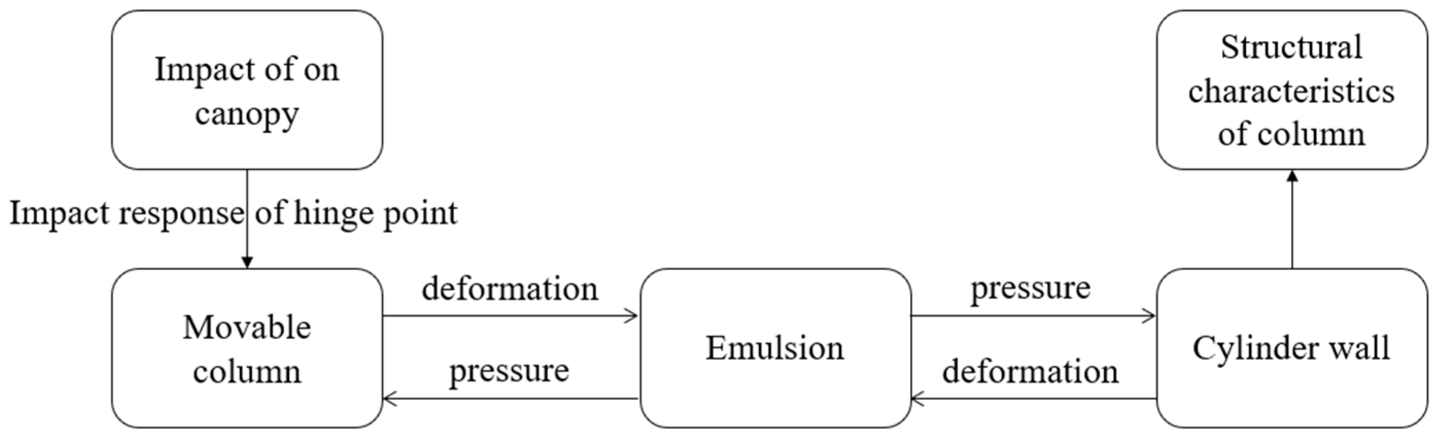
4.1. Fluid-Structure Interaction Model of the Column

In fact, when the canopy is subjected to the impact load, the liquid pressure in the cylinder of the column will change, which will affect the cylinder wall and the movable column. At the same time, the deformation of the cylinder wall and the movable column will also affect the change of the liquid in the cylinder. Therefore, based on the fluid–structure interaction theory, the fluid–structure interaction response of the column under the impact load is analyzed. The interaction process of the column is shown in Figure 9.
Due to the frequent data exchange between the fluid and the structure, the calculation is large in the fluid–structure interaction analysis. Therefore, in the case of less influence on the result data, the column is simplified, ignoring the weld and chamfer structure. At the same time, the column has an axisymmetric structure, and half of the model is selected for fluid–structure interaction analysis. The column and the guide sleeve materials are selected as 27SiMn, and the fluid medium is the emulsion with the water content of 95%. The structural size parameters are shown in Table 2. The fluid domain and solid domain are segmented to improve the mesh quality, and the hexahedral mesh is used to ensure the calculation accuracy and reduce the calculation amount. The fluid–structure interaction model of the column is shown in Figure 10.
In Figure 10a, since the pressure and volume changes of the liquid cannot be ignored, the fluid domain is defined as compressible fluid. The coupling surface between the fluid domain and the solid domain should satisfy one-to-one correspondence. In the dynamic mesh setting, using the method of Remeshing and Smoothing mesh updating, the dynamic mesh area is selected as the fluid-solid coupling surface and defined as system coupling. In Figure 10b, the one-level guide sleeve and the two-level guide sleeve are connected with the corresponding cylinder body by a thread in the actual situation, but the thread is not created in the column modeling. Therefore, the contact type between the guide sleeve and the cylinder body is defined as binding contact, and the other positions are positioned as friction contact. The column hinge force is applied at the hinge hole of the movable column, and the full constraint is defined at the bottom of the one-level cylinder. The data connection between the fluid domain and the solid domain is established in the System Coupling module, and the convergence of the two is judged by the trend of the residual curve. After the fluid–structure interaction simulation is completed, the Result module is used to analyze the dynamic characteristics of the column under impact load.

4.2. Dynamic Characteristics of the Column Solid Domain

It can be seen from Figure 5 that when the impact load acts at the position (2, 8), the impact response of the hinge point of the column is the most intense. Therefore, the canopy is selected to be under normal load and the impact load acts at the position (2, 8) for comparative analysis. For the following comparative analysis, it is defined that the normal load of the canopy is the condition (a), and the impact load of the canopy is the condition (b). Through the fluid–structure interaction simulation of the column, the stress distribution of the column solid domain under condition (a) is shown in Figure 11, and the stress distribution of the column solid domain under condition (b) is shown in Figure 12, where the stress is von Mises stress and the unit is Pa.
On the whole, the stress distribution of the column solid domain is the same under the two conditions. The stress values of the one-level cylinder and the two-level cylinder show a downward trend of gradual increase. Due to the direct effect of the hinge force, the stress concentration exists at the hinge joint of the movable column, and the stress distribution of the movable column from top to bottom is relatively uniform. However, the stress of each component is different under different conditions, and the maximum stress values are less than the yield strength limit of the material, which is in a safe state.
It can be seen from Figure 12 that in condition (b), the analysis of reference [30,31] also supports this result, the stress values of the movable column and the two-level guide sleeve are significantly increased, and the maximum stress point of the two-level cylinder is transferred to the bottom of the cylinder, and the stress value of area A in the two-level cylinder is significantly increased. However, the one-level cylinder and its guide sleeve stress change little. This is because the amplitude of the impact load on the canopy is small, the external force on the column has not yet reached the initial pressure of the one-level cylinder, and the column is in the passive support stage, resulting in only the two-level cylinder being greatly affected by the impact load. Combined with the analysis of the guide sleeve stress and reference [32], due to the impact load, the pressure of the guide sleeve increases, especially the stress of the two-level guide sleeve increases obviously. Therefore, when the canopy is subjected to the impact load, the two-level cylinder will first appear in impact response. To ensure the supporting capacity of the column, the compressive and wear resistance of the inner surface of the two-level guide sleeve should be strengthened, and the bottom and wall of the two-level cylinder should be thickened to prevent cylinder expansion.
It can be seen from Figure 11 and Figure 12 that in conditions (a) and (b), the column is in the passive support stage, the two-level cylinder is compressed, and the one-level cylinder remains unchanged. To analyze the amount of liquid compression in the cylinder, the displacement of the movable column under two conditions is used to react. The displacement curve of the movable column is shown in Figure 13.
It can be seen from Figure 13 that the displacement of the movable column can be divided into three stages. In stage I, the displacement of the movable column changes little and is in an oscillating state. This is because the external force of the column in the initial state is less than the initial pressure of the two-level cylinder, and the liquid in the cylinder will not be compressed. In stage II, the displacement change of the movable column shows an increasing trend of gradual attenuation of fluctuation. This is because the external force of the column exceeds the initial pressure of the two-level cylinder, and the liquid in the cylinder begins to be compressed, resulting in the continuous increase of the liquid pressure in the cylinder, and then the force on the movable column is increasing, so that the displacement fluctuation of the movable column is continuously attenuated. In stage III, the displacement state of the column tends to be stable in condition (a) because there is no impact load in condition (a), and the maximum displacement is 8.66 mm. When the canopy is subjected to the impact load, it can be seen from the third stage of the condition (b) that the displacement of the movable column will increase significantly. With the continuous effect of the impact load, the displacement fluctuation of the movable column decreases gradually, and the maximum displacement is 11.85 mm. This is because the external force on the column suddenly increases, the pressure balance of the liquid in the cylinder is broken, the displacement of the movable column is mutated, and the liquid in the cylinder is compressed, resulting in the continuous increase of the liquid pressure in the cylinder and gradually tending to balance. Therefore, when the canopy is subjected to the impact load, the movable column will appear obvious displacement, resulting in increased the liquid pressure in the cylinder, thereby increasing the force on the cylinder wall. To reduce the occurrence of cylinder expansion, the wall thickness of the cylinder should be appropriately increased, and the safety valve should be checked regularly to ensure that the safety valve can work normally and avoid the excessive pressure of the liquid in the cylinder.

4.3. Dynamic Characteristics of the Column Fluid Domain

It can be seen from Figure 13 that due to the effect of the impact load, the movable column will appear an obvious shrinkage phenomenon, so that the liquid in the cylinder is continuously compressed, resulting in a continuous increase of the liquid pressure. To intuitively see the impact load on the column fluid domain pressure, the column fluid domain pressure changes in condition (a) and condition (b) are compared. The pressure distribution of the one-level cylinder fluid domain is shown in Figure 14, and the pressure distribution of the two-level cylinder fluid domain is shown in Figure 15.
It can be seen from Figure 14 that the pressure in the fluid domain of the one-level cylinder is in a stepped distribution, and the pressure value increases gradually from the fluid–structure interaction to the bottom of the cylinder. When the canopy is subjected to the impact load, the pressure in the fluid domain of the one-level cylinder fluctuates. As the impact load continues, the pressure value increases, but the pressure difference in the fluid domain of the one-level cylinder before and after the impact is only 0.09 MPa. Therefore, when the impact load amplitude of the canopy is small, the pressure change in the fluid domain of the one-level cylinder is gentle, and the safety factor of the one-level cylinder is high.
It can be seen from Figure 15 that the pressure in the fluid domain of the two-level cylinder is also in a stepped distribution, and its pressure value is significantly higher than that in the fluid domain of the one-level cylinder. When the canopy is subjected to the impact load, the two-level cylinder pressure continues to increase, and the pressure difference before and after the impact is 5.6 Mpa. This is because the fluid domain of the two-level cylinder is directly in contact with the movable column. When the movable column is retracted by an external force, the pressure balance of the liquid in the two-level cylinder is broken, and the liquid in the cylinder is compressed, resulting in a continuous increase of the pressure in the cylinder. Therefore, when the canopy is subjected to the impact load, the pressure in the two-level cylinder will increase significantly, and the pressure on the cylinder wall will also increase. Therefore, the structural performance of the two-level cylinder should be more considered in the column design, and the wall thickness of the two-level cylinder can be appropriately increased if necessary.
When the canopy is subjected to the impact load, the fluid domain of the two-level cylinder will be compressed, and the flow state of the fluid domain will change. To intuitively see the impact load on the flow velocity in the fluid domain of the two-level cylinder, the symmetry plane of the two-level cylinder is selected, and the streamline distribution in the fluid domain of the two-level cylinder in the condition (a) and condition (b) is compared, as shown in Figure 16.
It can be seen from Figure 16 that in working condition (a), the flow velocity in the fluid domain of the two-level cylinder shows a layered distribution, and the flow velocity decreases gradually from top to bottom. The analysis of reference [19] also supports this result. The overall flow velocity is small, and there is a small eddy current on both sides of the bottom of the two-level cylinder. In condition (b), the flow velocity increases significantly in the early stage of impact. This is because the pressure balance of the liquid is broken and the liquid in the cylinder is compressed, resulting in a sharp flow of liquid in the cylinder. With the continuous effect of the impact load, the streamlines at the bottom of the two-level cylinder gradually gather, forming a sparse situation on both sides of the close middle, and a large eddy current will appear on both sides of the bottom. This is because under the impact load, the rapid flow of liquid in the cylinder, so that the liquid and the bottom of the cylinder produce a violent collision, while the cylinder space is compressed, liquid scattered around, resulting in a vortex on both sides of the bottom of the cylinder. At the end of the impact, the streamline gradually tends to be flat, and the flow velocity change is relatively stable. This is because the liquid pressure in the cylinder gradually tends to balance, and the flow state gradually becomes stable. Therefore, when the canopy is subjected to the impact load, the flow state in the fluid domain of the two-level cylinder will change, the liquid velocity will continue to increase, and the bottom of the cylinder will be greatly collided.

5. Conclusions

To reduce the impact failure of the hydraulic support and reveal the impact response of the canopy hinge point and the flow field response of the column under the impact load, the impact dynamic model of the hydraulic support and the fluid–structure interaction model of the column are established. The influence of the impact load position on the impact response of the canopy hinge point is analyzed, and the impact response characteristics of the column flow field are discussed. The following conclusions are obtained:
(1)
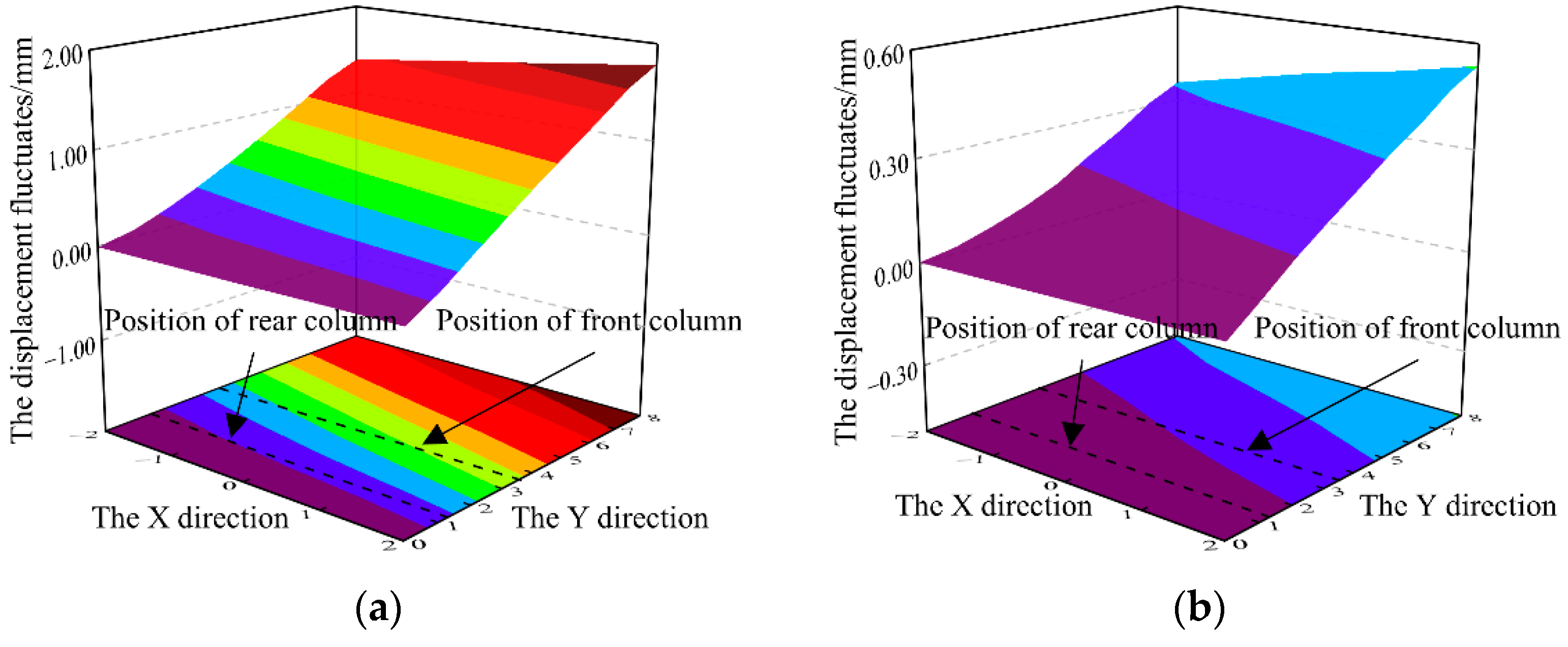
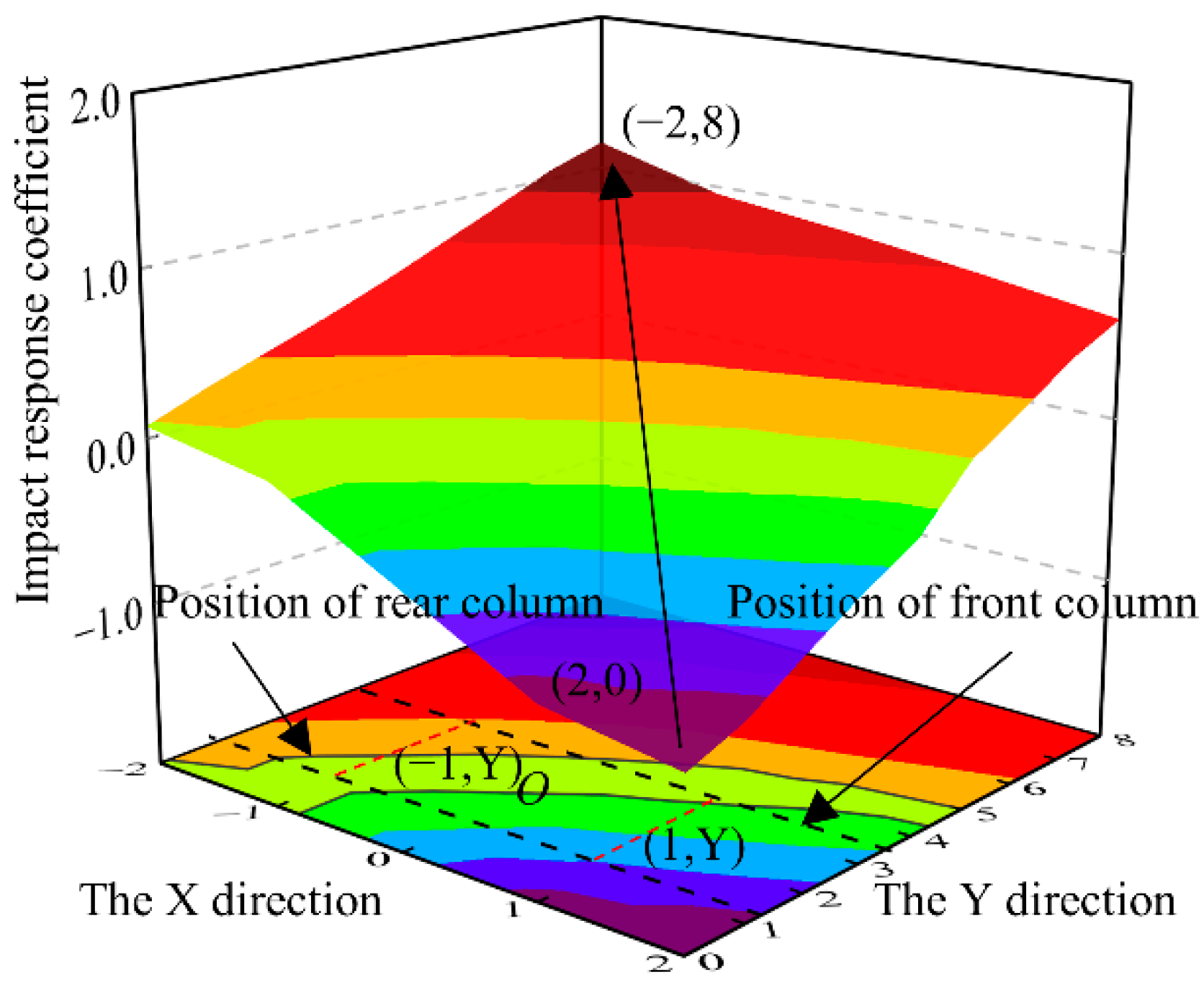
When the impact load acts at the front end of the canopy, the impact response of the hinge point of the canopy is large, and the pin shaft with higher yield strength should be selected to avoid the fracture failure of the pin shaft. When the impact load acts between the front column action line and the rear column action line, the impact response of the canopy hinge point is small, and it has good impact adaptability.
(2)
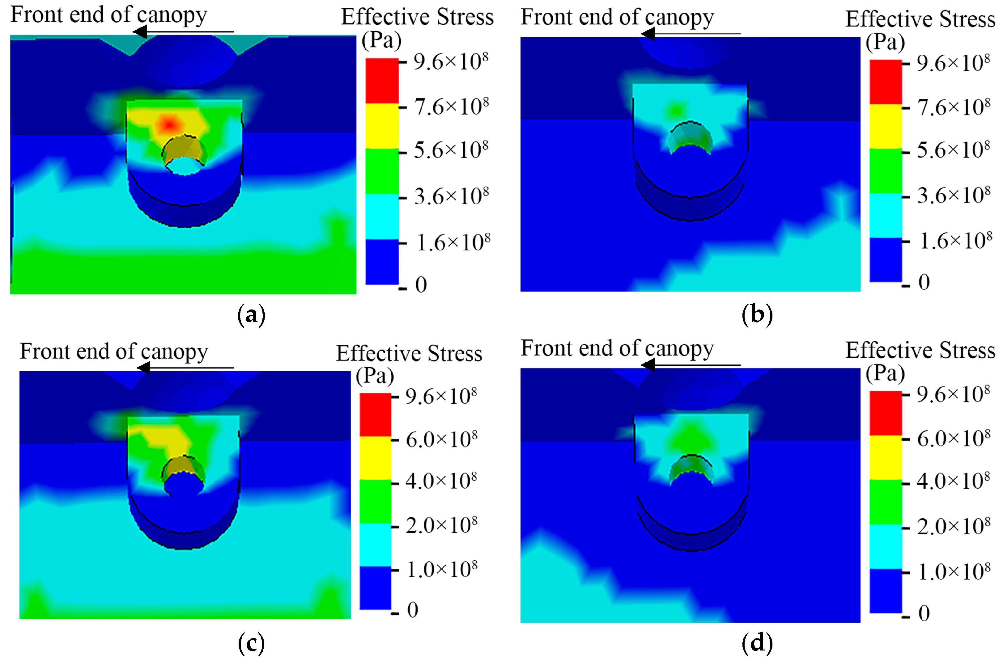
For the column hinge point, the impact response of the front column hinge point is more intense, and it is prone to impact failure above the front column hinge hole. Therefore, the front column hinge hole should be strengthened. For the hinge point of the caving shield, when the impact load changes along the width of the canopy, it shows obviously the eccentric load effect, which should ensure the uniform force of the canopy. Therefore, in the process of hydraulic support optimization, the adaptability of each hinge point under different working conditions should be fully considered.
(3)
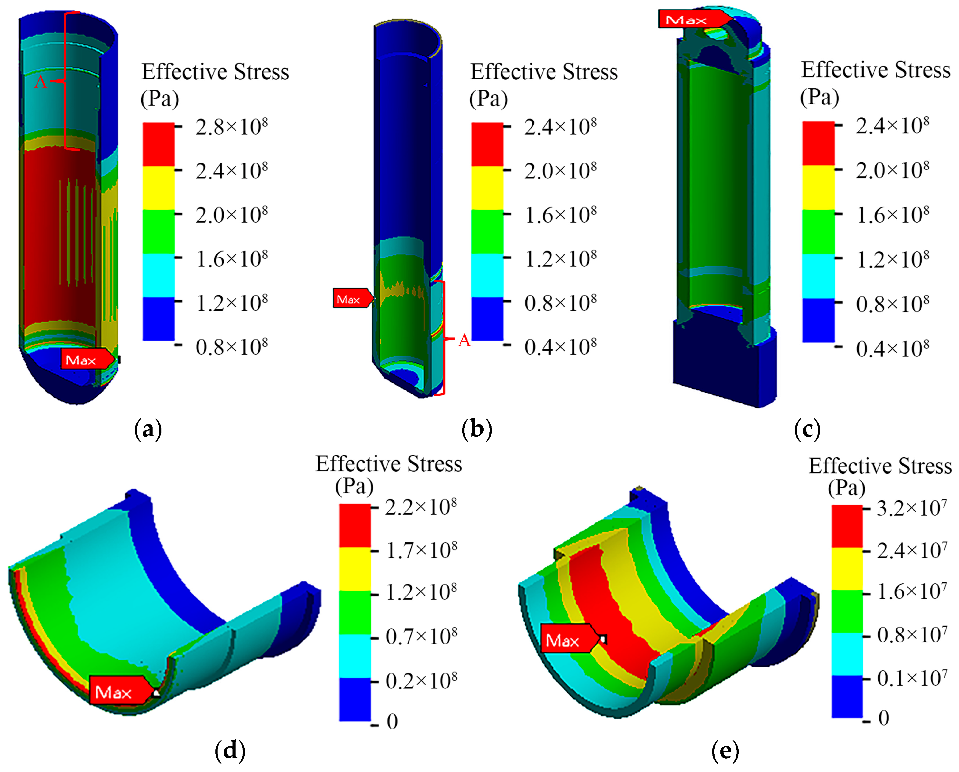
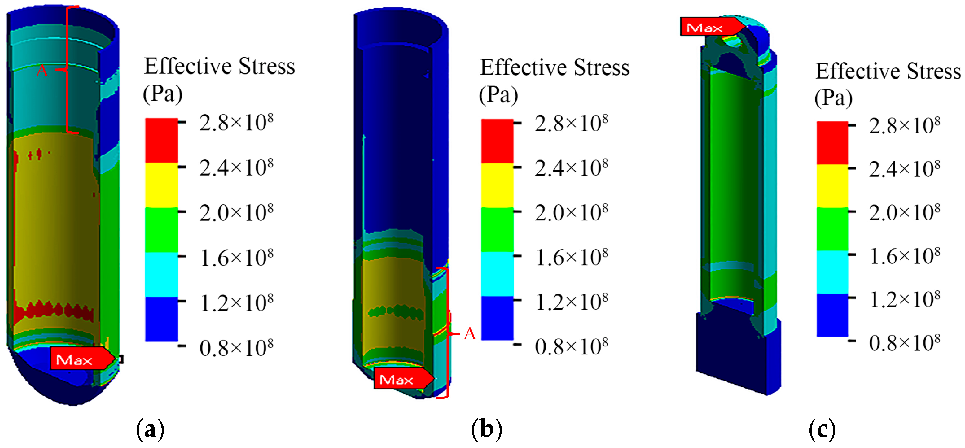
Under the impact load, the stress concentration area of the column is at the bottom of the column, so when designing the structure of the column, it should strengthen the optimization design of the bottom of the column. The stress value of the two-level guide sleeve increases significantly, and the compressive and wear resistance of the inner surface of the two-level guide sleeve should strengthen.
(4)
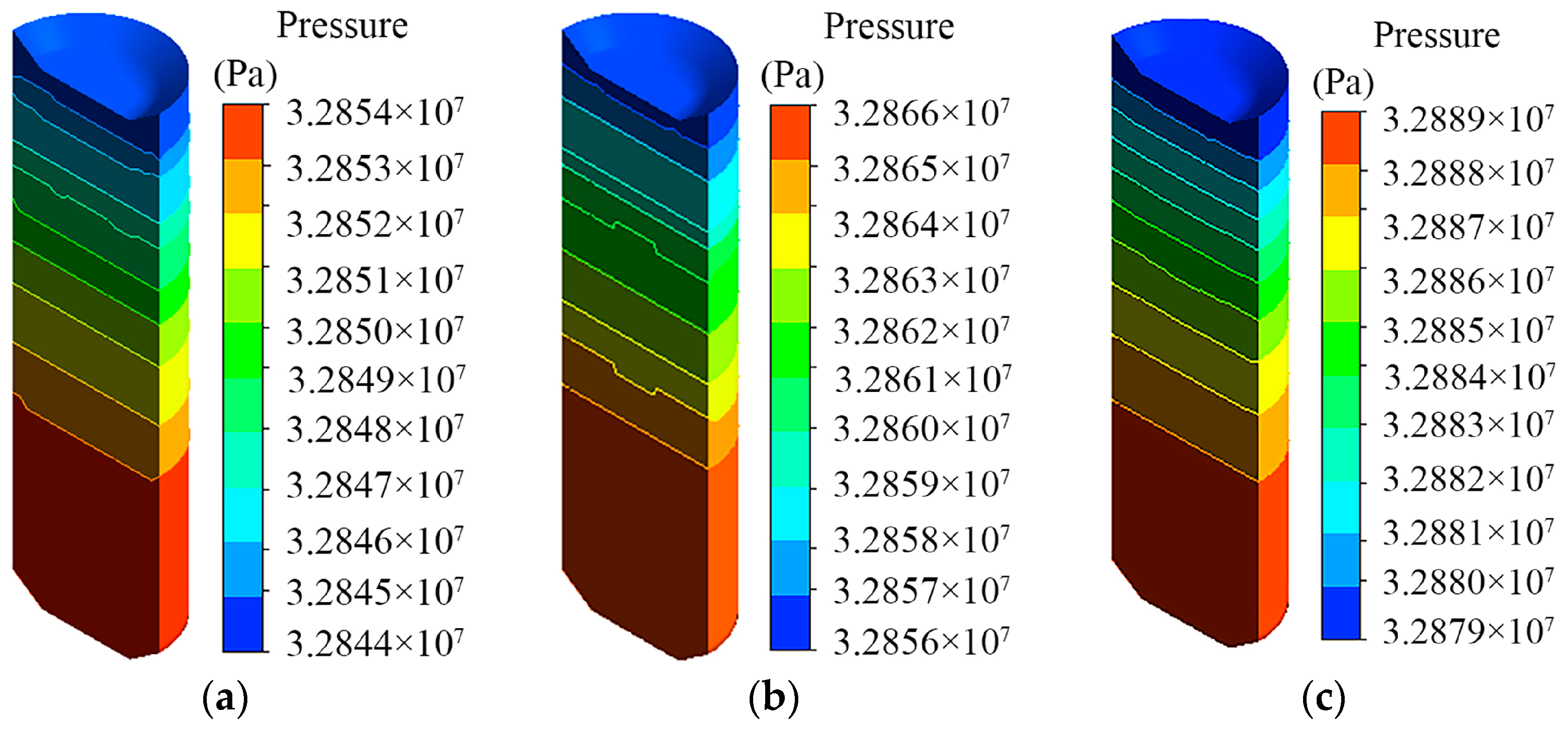
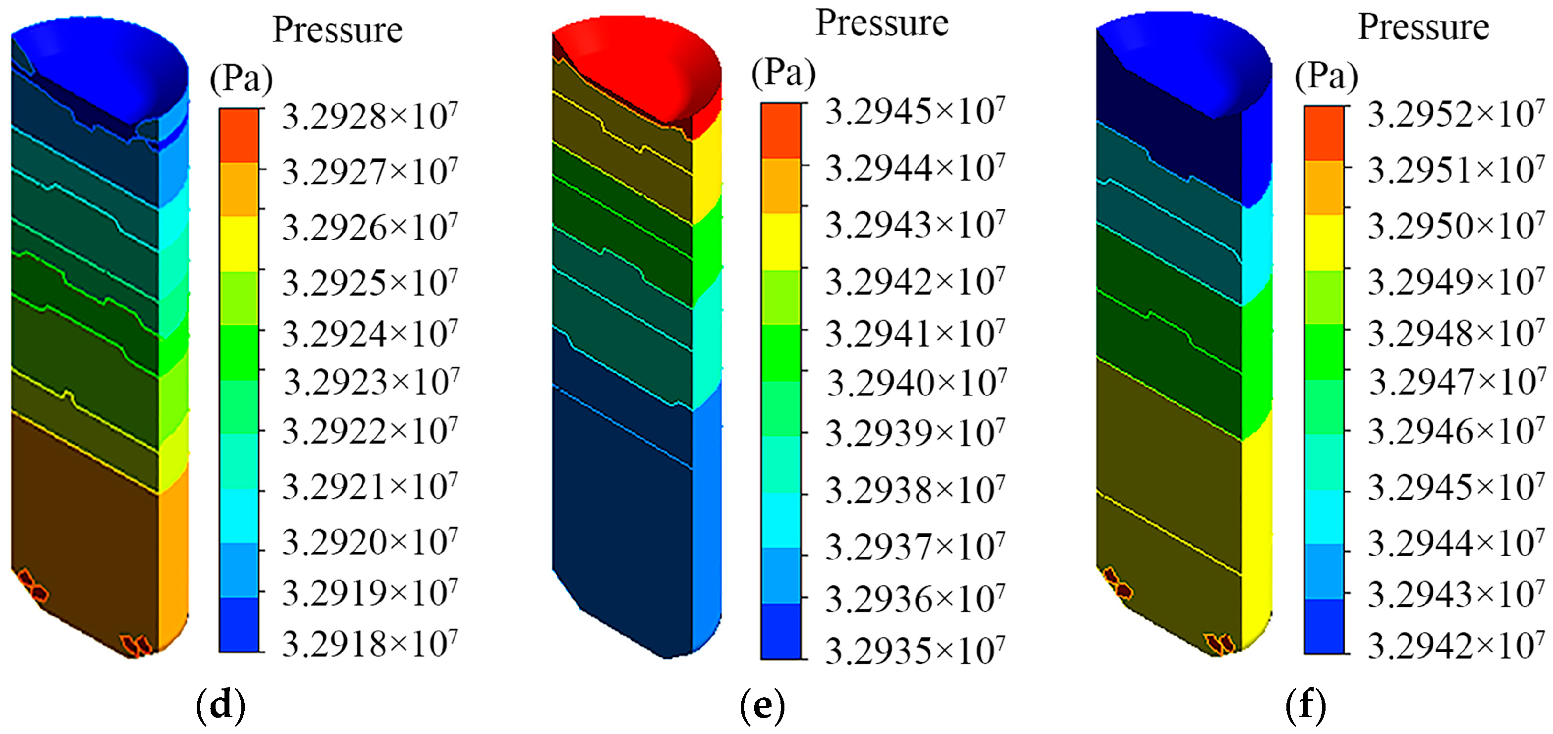
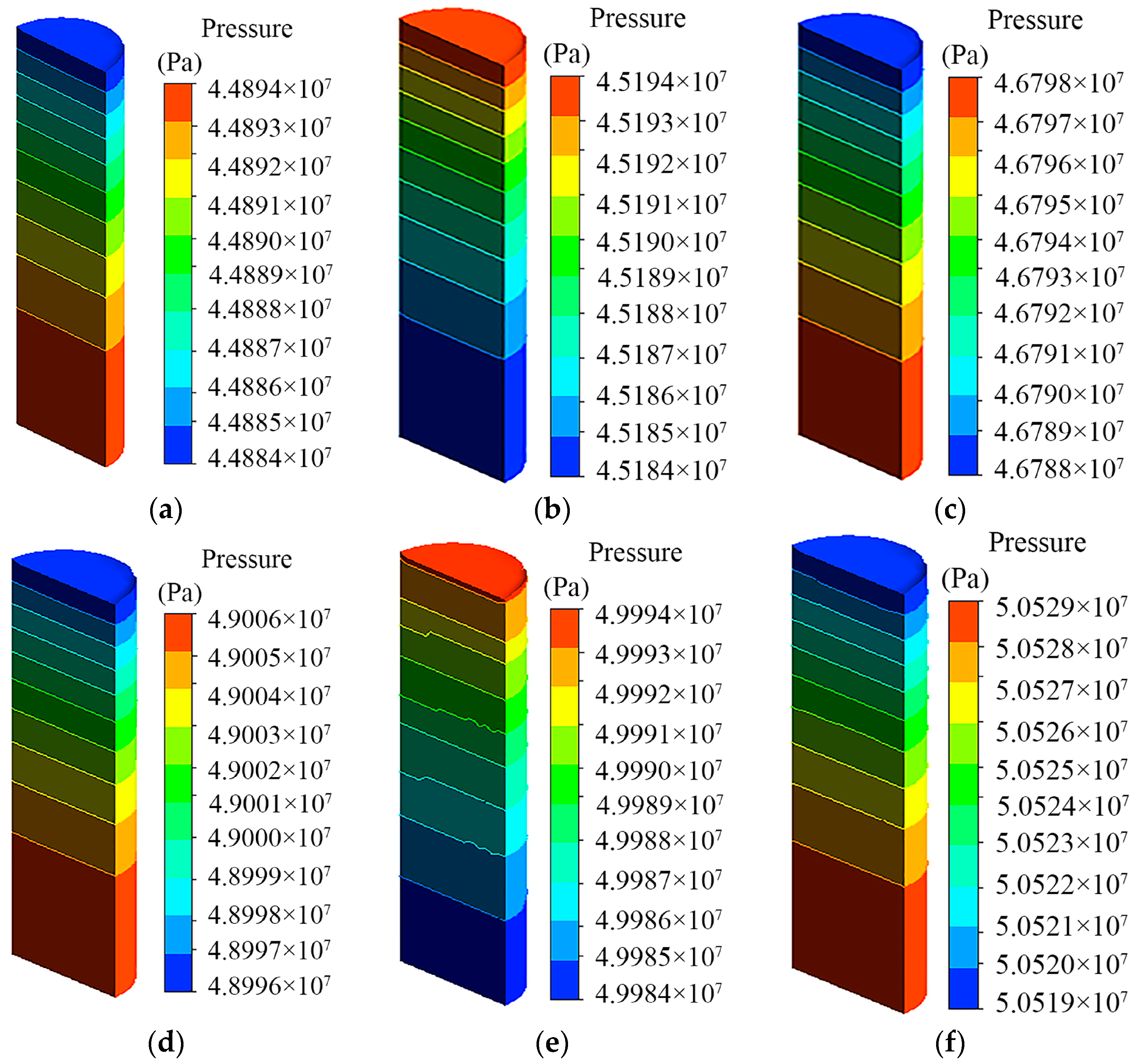
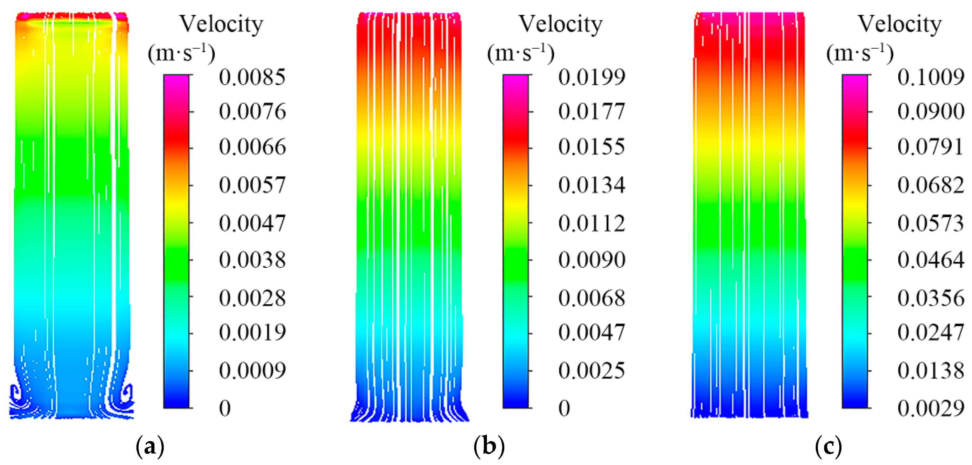
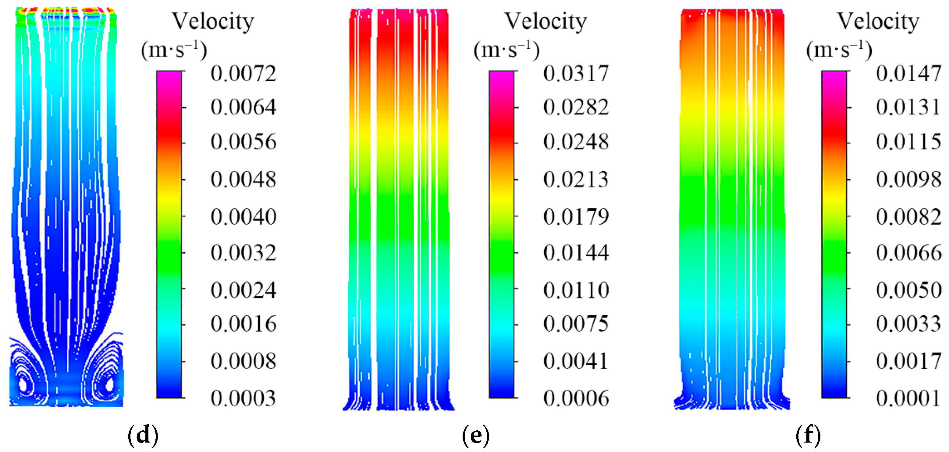
Due to the impact load, the pressure and flow rate of the two-level cylinder liquid will increase significantly. In the middle of the shock, the streamline in the two-level cylinder will be sparse on both sides of the middle close, and a large eddy current will appear on both sides of the bottom of the cylinder. Therefore, the influence of liquid cannot be ignored in the design of column structure.
The results provide references for exploring the response characteristics of the hydraulic support under the impact load and provide references for structural optimization of the anti-impact hydraulic support and strength design of the column. The influence of the floor is not considered in this study, so the coupling model of the hydraulic support including the floor can be considered in further research.

Author Contributions

Conceptualization, Q.Z. and Z.L.; methodology, Q.Z.; software, J.W.; validation, Z.L., D.M. and L.W.; formal analysis, J.W.; investigation, Z.L.; data curation, Z.L. and J.W.; writing—original draft preparation, Z.L.; writing—review and editing, Z.L.; visualization, Z.L.; supervision, Q.Z.; project administration, L.W.; funding acquisition, Q.Z. All authors have read and agreed to the published version of the manuscript.

Funding

This research was funded by the National Natural Science Foundation of China (Grant No. 51974170), the Key Research and Development of Shandong Province (Grant No. 2019SDZY01), and the Natural Science Foundation of Shandong Province (Grant No. ZR2019MEE067).

Institutional Review Board Statement

Not applicable.

Informed Consent Statement

Not applicable.

Data Availability Statement

Data were curated by the authors and are available upon request.

Conflicts of Interest

The authors declare no conflict of interest.

References

  1. Meng, Z.S.; Zhang, J.M.; Xie, Y.Y.; Lu, Z.G.; Zeng, Q.L. Analysis of the Force Response of a Double-Canopy Hydraulic Support under Impact Loads. Int. J. Simul. Model. 2021, 20, 766–777. [Google Scholar] [CrossRef]
  2. Wang, G.F.; Pang, Y.H.; Li, M.Z.; Ma, Y.; Liu, X.H. Hydraulic support and coal wall coupling relationship in ultra large height mining face. J. China Coal Soc. 2017, 42, 518–526. [Google Scholar] [CrossRef]
  3. Verma, A.K.; Deb, D. Numerical Analysis of an Interaction between Hydraulic-Powered Support and Surrounding Rock Strata. Int. J. Geomech. 2013, 13, 181–192. [Google Scholar] [CrossRef]
  4. Xu, Y.J.; Wang, G.F.; Ren, H.W. Theory of coupling relationship between surrounding rocks and powered support. J. China Coal Soc. 2015, 40, 2528–2533. [Google Scholar] [CrossRef]
  5. Lin, J.Z.; Yang, T.R.; Ni, K.X.; Han, C.Y.; Ma, H.; Gao, A.; Xiao, C.L. Effects of boundary conditions on stress distribution of hydraulic support: A simulation and experimental study. Adv. Mech. Eng. 2021, 13, 16878140211001194. [Google Scholar] [CrossRef]
  6. Zhai, G.D.; Yang, X.; Lu, X.H.; Ji, R.J.; Hu, W.Y. Finite Element Analysis of Canopy Column Socket and Column Hinge Joint of Hydraulic Support. Coal Mine Mach. 2021, 42, 64–66. [Google Scholar] [CrossRef]
  7. Zeng, X.T.; Meng, G.Y.Z.; Heng, K. Force Transmission Analysis of Sliding Block-Type Hydraulic Support under Impact Loads. Int. J. Simul. Model. 2019, 18, 100–111. [Google Scholar] [CrossRef]
  8. Wang, D.L.; Zeng, X.T.; Wang, G.F.; Li, R. Adaptability Analysis of Four-Leg Hydraulic Support with Large Mining Height under Impact Dynamic Load. Shock Vib. 2022, 2022, 2168871. [Google Scholar] [CrossRef]
  9. Ren, H.W.; Zhang, D.S.; Gong, S.X.; Zhou, K.; Xi, C.Y.; He, M.; Li, T.J. Dynamic impact experiment and response characteristics analysis for 1:2 reduced-scale model of hydraulic support. Int. J. Min. Sci. Technol. 2021, 31, 347–356. [Google Scholar] [CrossRef]
  10. Szurgacz, D.; Brodny, J. Adapting the Powered Roof Support to Diverse Mining and Geological Conditions. Energies. 2020, 13, 405. [Google Scholar] [CrossRef] [Green Version]
  11. Li, T.D.; Wang, J.R.; Zhang, K.; Zhang, C.H. Mechanical analysis of the structure of longwall mining hydraulic support. Sci. Prog. 2020, 103, 0036850420936479. [Google Scholar] [CrossRef] [PubMed]
  12. Yang, Z.K.; Sun, Z.Y.; Jiang, S.B.; Mao, Q.H.; Liu, P.; Xu, C.Z. Structural Analysis on Impact-Mechanical Properties of Ultra-High Hydraulic Support. Int. J. Simul. Model. 2020, 19, 17–28. [Google Scholar] [CrossRef]
  13. Zeng, Q.L.; Meng, Z.S.; Wan, L.R.; Wang, C.L. Analysis on Force Transmission Characteristics of Two-Legged Shield Support under Impact Loading. Shock Vib. 2018, 2018, 3854684. [Google Scholar] [CrossRef] [Green Version]
  14. Liang, L.C.; Tian, J.J.; Zheng, H.; Jiao, S.J. A study on force transmission in a hydraulic support under impact loading on its canopy beam. J. China Coal Soc. 2015, 40, 2522–2527. [Google Scholar] [CrossRef]
  15. Liu, Y.Z.; Shi, W.; Wang, W.H.; Li, X.; Qi, S.; Wang, B. Dynamic Analysis of Monopile-Type Offshore Wind Turbine Under Sea Ice Coupling With Fluid-Structure Interaction. Front. Mar. Sci. 2022, 9. [Google Scholar] [CrossRef]
  16. Liang, Z.J.; Guo, C.Y.; Wang, C.S. The Connection between flow pattern evolution and vibration in 90-degree pipeline: Bidirectional fluid-structure interaction. Energy Sci. Eng. 2021, 10, 308–323. [Google Scholar] [CrossRef]
  17. Wang, Y.F.; Wang, J.; He, Z.L.; Sun, J.W.; Wang, T.; Liu, C.H. Investigation on Dynamic Characteristics of the Reed Valve in Compressors Based on Fluid-Structure Interaction Method. Appl. Sci. 2021, 11, 3946. [Google Scholar] [CrossRef]
  18. Guo, Q.; Zhou, J.X.; Guan, X.L. Fluid–structure interaction in Z-shaped pipe with different supports. Acta Mech. Sin. 2020, 36, 513–523. [Google Scholar] [CrossRef]
  19. Guo, W.J.; Lu, C.Y.; Yan, X.L.; Wen, X.L.; Wang, H.F. On Transient Flow Field of Asymmetric Hydraulic Cylinder at Start-up. Sci. Technol. Eng. 2020, 20, 4338–4344. [Google Scholar]
  20. Qu, W.; Zhang, H.L.; Li, W.; Sun, W.Q.; Zhao, L.N.; Ning, H.H. Influence of Support Stiffness on Dynamic Characteristics of the Hydraulic Pipe Subjected to Basic Vibration. Shock Vib. 2018, 2018, 4035725. [Google Scholar] [CrossRef]
  21. Szurgacz, D.; Brodny, J. Analysis of the Influence of Dynamic Load on the Work Parameters of a Powered Roof Support’s Hydraulic Leg. Sustainability 2019, 11, 2570. [Google Scholar] [CrossRef] [Green Version]
  22. Szurgacz, D. Dynamic Analysis for the Hydraulic Leg Power of a Powered Roof Support. Energies 2021, 14, 5715. [Google Scholar] [CrossRef]
  23. Xu, W. Study on Load Characteristics of Hydraulic Support Column under Impact Load. Coal Mine Mach. 2021, 42, 63–66. [Google Scholar] [CrossRef]
  24. Sui, X.H.; Liu, C.; Su, X.; He, J. Performance Analysis of Cylinder Body of Telescopic Cylinder Based on Fluid-solid Coupling. Coal Mine Mach. 2015, 36, 113–115. [Google Scholar] [CrossRef]
  25. Liu, X.K.; Zhao, Z.H.; Zhao, Y. Study on Dynamic Features of Leg Applied to Hydraulic Powered Support Under Bumping Load. Coal Sci. Technol. 2012, 40, 66–70. [Google Scholar] [CrossRef]
  26. Tomski, L.; Uzny, S. A hydraulic cylinder subjected to Euler’s load in aspect of the stability and free vibrations taking into account discrete elastic elements. Arch. Civ. Mech. Eng. 2011, 11, 769–785. [Google Scholar] [CrossRef]
  27. Liang, L.C.; Ren, H.W.; Zheng, H. Analysis on mechanical-hydraulic coupling rigidity characteristics of hydraulic powered support. Coal Sci. Technol. 2018, 46, 141–147. [Google Scholar] [CrossRef]
  28. Feng, H.; Du, Q.G.; Huang, Y.X.; Chi, Y.B. Modeling Study on Stiffness Characteristics of Hydraulic Cylinder under Multi-Factors. Stroj. Vestn.-J. Mech. Eng. 2017, 63, 447–456. [Google Scholar] [CrossRef] [Green Version]
  29. Jiang, W.; Luo, X.; Chen, X.D. Influence of structural flexibility on the nonlinear stiffness of hydraulic system. Adv. Mech. Eng. 2016, 8, 1687814016663806. [Google Scholar] [CrossRef] [Green Version]
  30. Li, Z.G.; Chen, Y.M.; Zhong, D.H.; Zhang, K.; Huang, L.S.; Liu, Y.; Li, Y.X. Fatigue Analysis of Hydraulic Support Column Based on Fluid-solid Coupling. Coal Mine Mach. 2022, 43, 72–74. [Google Scholar] [CrossRef]
  31. Świątek, J.; Janoszek, T.; Cichy, T.; Stoiński, K. Computational Fluid Dynamics Simulations for Investigation of the Damage Causes in Safety Elements of Powered Roof Supports—A Case Study. Energies 2021, 14, 1027. [Google Scholar] [CrossRef]
  32. Zhang, R.; Jiang, F.; Yang, J.; Hu, T.W.; Wang, W.Q. Fluid-structure Coupling Analysis of Hydraulic Cylinder Based on Dynamic Mesh Technology. China Mech. Eng. 2017, 28, 156–162. [Google Scholar]
Figure 1. Dynamic model of hydraulic support.
Energies 15 04638 g001
Figure 2. Equivalent replacement of column and spring damping model.
Energies 15 04638 g002
Figure 3. Axial force-deformation curve of spring.
Energies 15 04638 g003
Figure 4. Location of the impact load.
Energies 15 04638 g004
Figure 5. (a) Impact response coefficient of the hinge point of the front column. (b) Impact response coefficient of the hinge point of the rear column.
Energies 15 04638 g005
Figure 6. (a) Vertical displacement fluctuation of the hinge point of the front column. (b) Vertical displacement fluctuation of the hinge point of the rear column.
Energies 15 04638 g006
Figure 7. (a) Stress distribution of the hinged hole of the front column under impact load. (b) Stress distribution of the hinged hole of the rear column under impact load. (c) Stress distribution of the hinged hole of the front column under normal load. (d) Stress distribution of the hinged hole of the rear column under normal load.
Energies 15 04638 g007
Figure 8. Impact response coefficient of the hinge point of the caving shield.
Energies 15 04638 g008
Figure 9. Fluid-structure interaction process of the column.
Energies 15 04638 g009
Figure 10. (a) Mesh of the column fluid domain. (b) Mesh of the column solid domain.
Energies 15 04638 g010
Figure 11. (a) Stress distribution of the one-level cylinder under condition (a). (b) Stress distribution of the two-level cylinder under condition (a). (c) Stress distribution of the movable column under condition (a). (d) Stress distribution of the hinged hole of the one-level guide sleeve under condition (a). (e) Stress distribution of the two-level guide sleeve under condition (a).
Energies 15 04638 g011
Figure 12. (a) Stress distribution of the one-level cylinder under condition (b). (b) Stress distribution of the two-level cylinder under condition (b). (c) Stress distribution of the movable column under condition (b). (d) Stress distribution of the hinged hole of the one-level guide sleeve under condition (b). (e) Stress distribution of the two-level guide sleeve under condition (b).
Energies 15 04638 g012aEnergies 15 04638 g012b
Figure 13. Displacement curve of the movable column.
Energies 15 04638 g013
Figure 14. (a) Pressure distribution in the fluid domain of the one-level cylinder under condition (a). (b) Pressure distribution in the fluid domain of the one-level cylinder under impact 0.01 s. (c) Pressure distribution in the fluid domain of the one-level cylinder under impact 0.02 s. (d) Pressure distribution in the fluid domain of the one-level cylinder under impact 0.03 s. (e) Pressure distribution in the fluid domain of the one-level cylinder under impact 0.04 s. (f) Pressure distribution in the fluid domain of the one-level cylinder under impact 0.05 s.
Energies 15 04638 g014aEnergies 15 04638 g014b
Figure 15. (a) Pressure distribution in the fluid domain of the two-level cylinder under condition (a). (b) Pressure distribution in the fluid domain of the two-level cylinder under impact 0.01 s. (c) Pressure distribution in the fluid domain of the two-level cylinder under impact 0.02 s. (d) Pressure distribution in the fluid domain of the two-level cylinder under impact 0.03 s. (e) Pressure distribution in the fluid domain of the two-level cylinder under impact 0.04 s. (f) Pressure distribution in the fluid domain of the two-level cylinder under impact 0.05 s.
Energies 15 04638 g015
Figure 16. (a) Streamline distribution in the fluid domain of the two-level cylinder under condition (a). (b) Streamline distribution in the fluid domain of the two-level cylinder under impact 0.01 s. (c) Streamline distribution in the fluid domain of the two-level cylinder under impact 0.02 s. (d) Streamline distribution in the fluid domain of the two-level cylinder under impact 0.03 s. (e) Streamline distribution in the fluid domain of the two-level cylinder under impact 0.04 s. (f) Streamline distribution in the fluid domain of the two-level cylinder under impact 0.05 s.
Energies 15 04638 g016aEnergies 15 04638 g016b
Table 1. Material model parameters of steel plate.
D e n s i t y   k g / m 3 Y o u n g s   M o d u l u s   P a P o i s s o n s   R a t i o Y i e l d   S t r e s s   P a
7830 2.07 × 10 11 0.3 9.6 × 10 8
Table 2. Dimension parameters of column structure.
ColumnExternal Diameter/mmInternal Diameter/mmEmulsion Length/mm
front columnone-level cylinder4404001280
two-level cylinder3802901298
rear columnone-level cylinder4404001280
two-level cylinder3802901265
Table 3. Equivalent stiffness of columns in different stages.
ColumnFirst Stage(N/m)Second Stage(N/m)Third Stage(N/m)
front column 9.367 × 10 7 5.977 × 10 7
rear column 9.597 × 10 7 6.070 × 10 7
Publisher’s Note: MDPI stays neutral with regard to jurisdictional claims in published maps and institutional affiliations.

