
Dynamic Propagation and Shear Stress Disturbance of Multiple Hydraulic Fractures: Numerical Cases Study via Multi-Well Hydrofracturing Model with Varying Adjacent Spacings


Abstract
:1. Introduction
2. Combined Finite Element–Discrete Element Method Considering Thermal-Hydro-Mechanical Coupling
- (1)
- Solid deformation
- (2)
- Fluid flow
- (3)
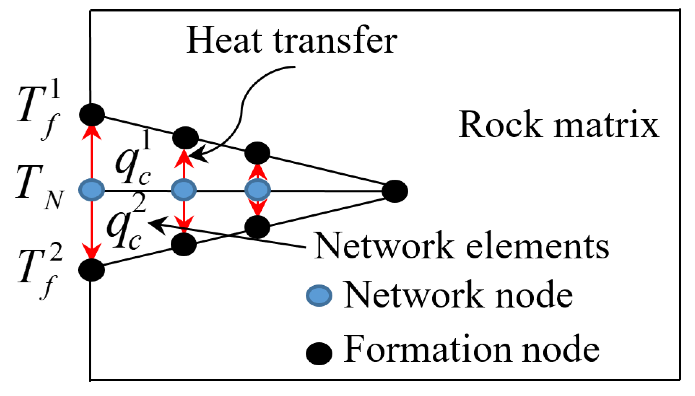
- Heat transfer
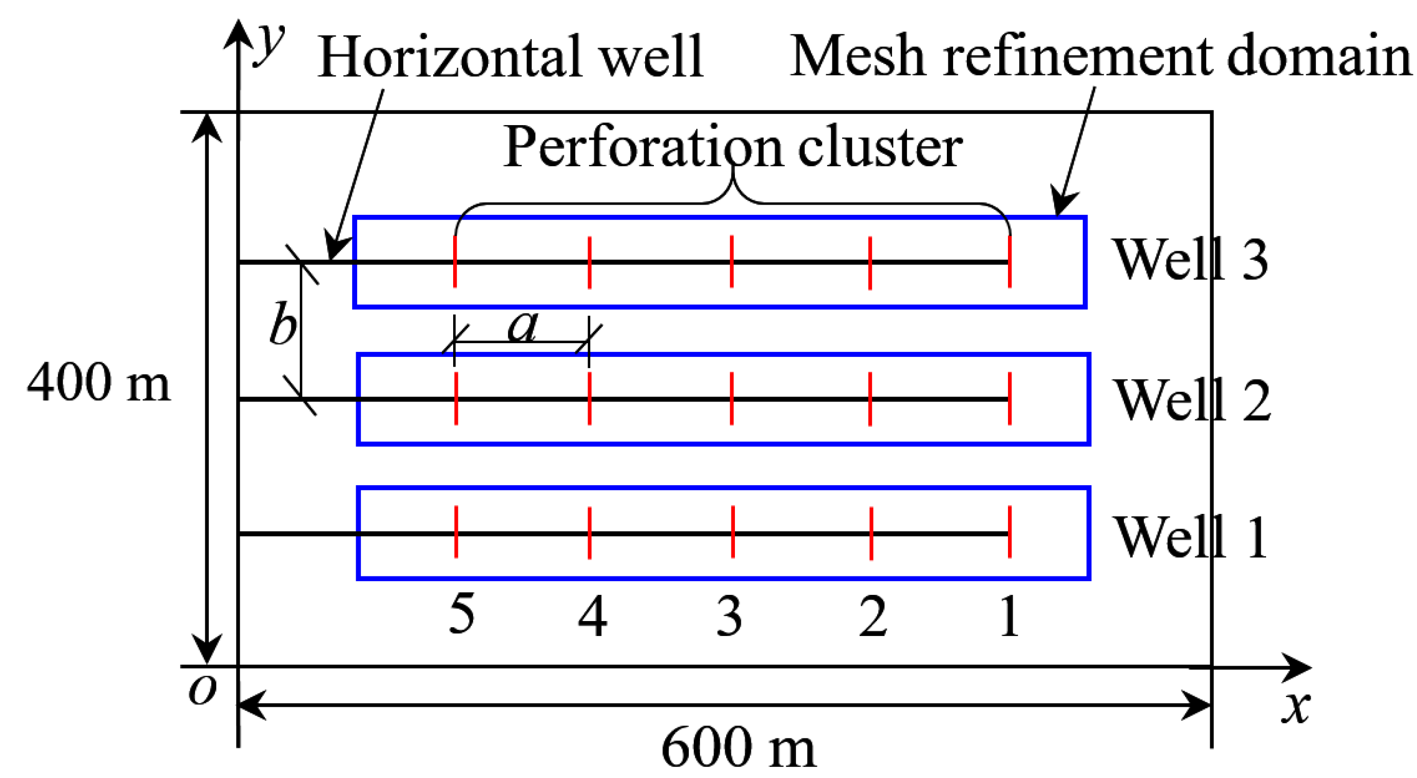
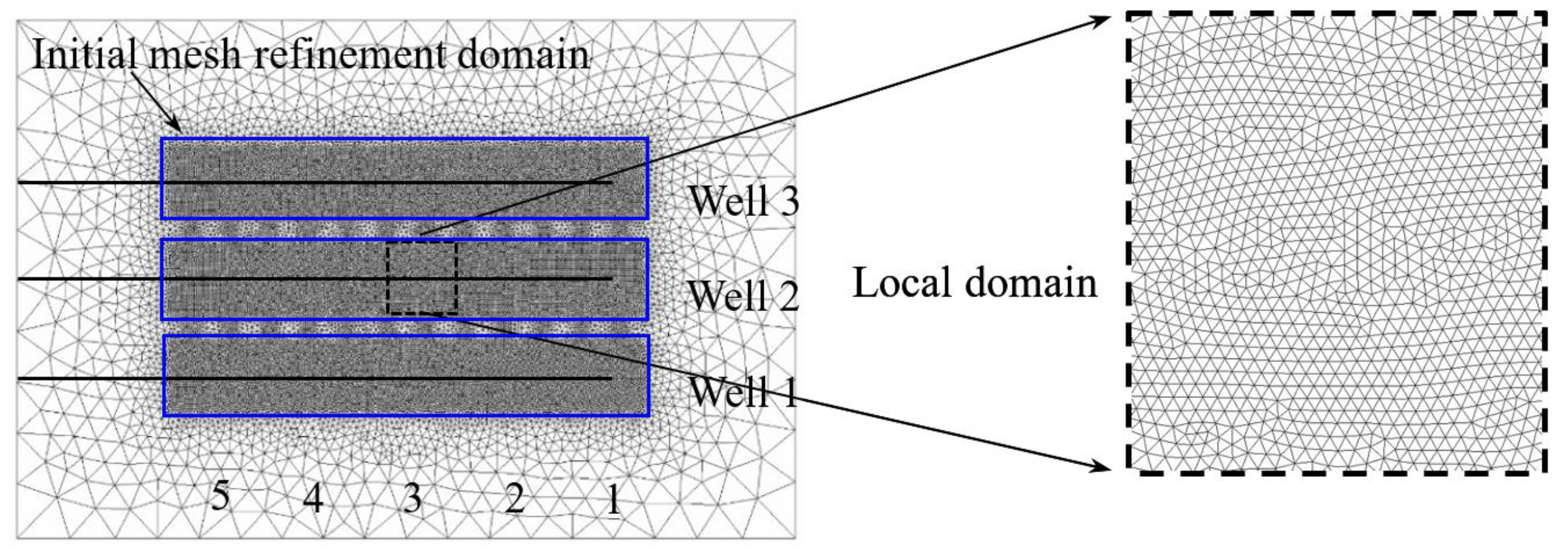
3. Numerical Models and Cases of Multiple Horizontal Wells
4. Results and Discussions
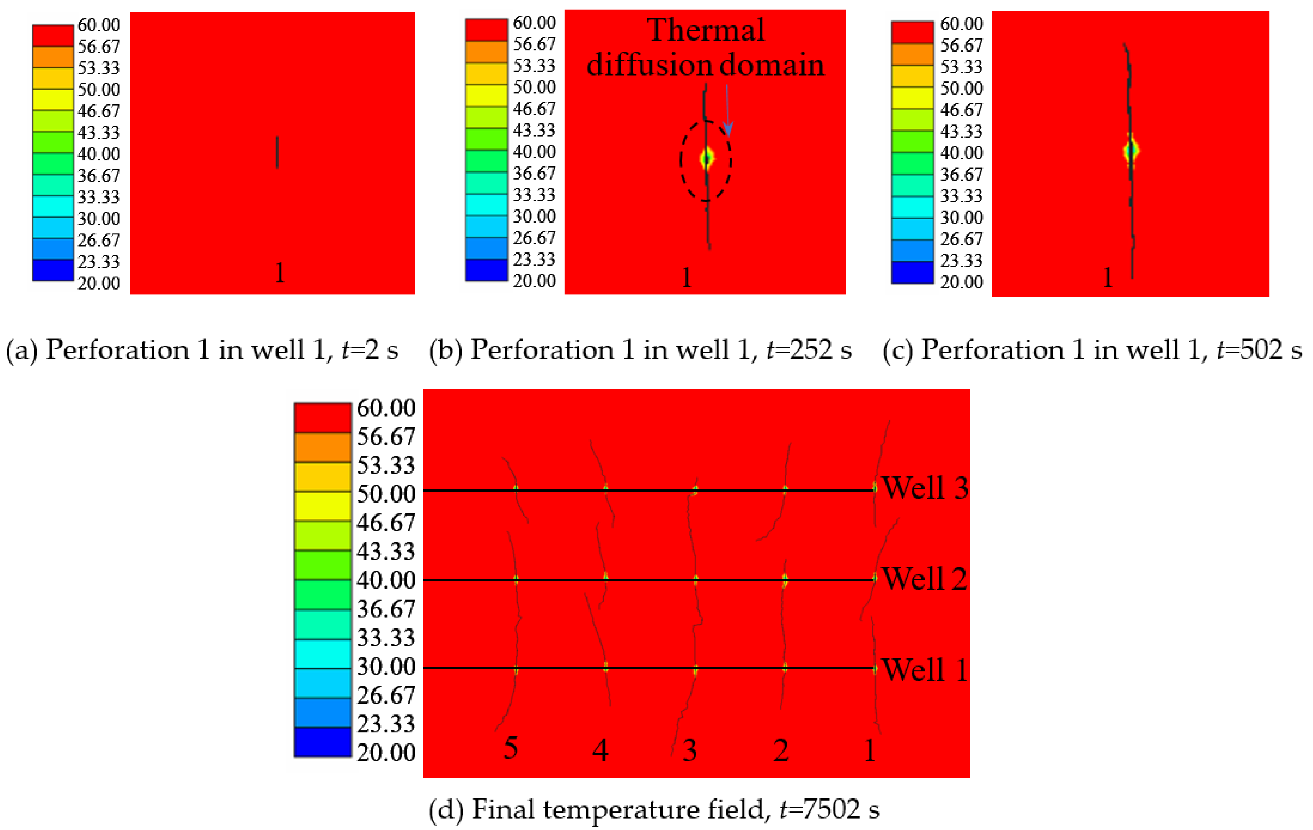
4.1. Thermal Diffusion in Fracture Propagation Process
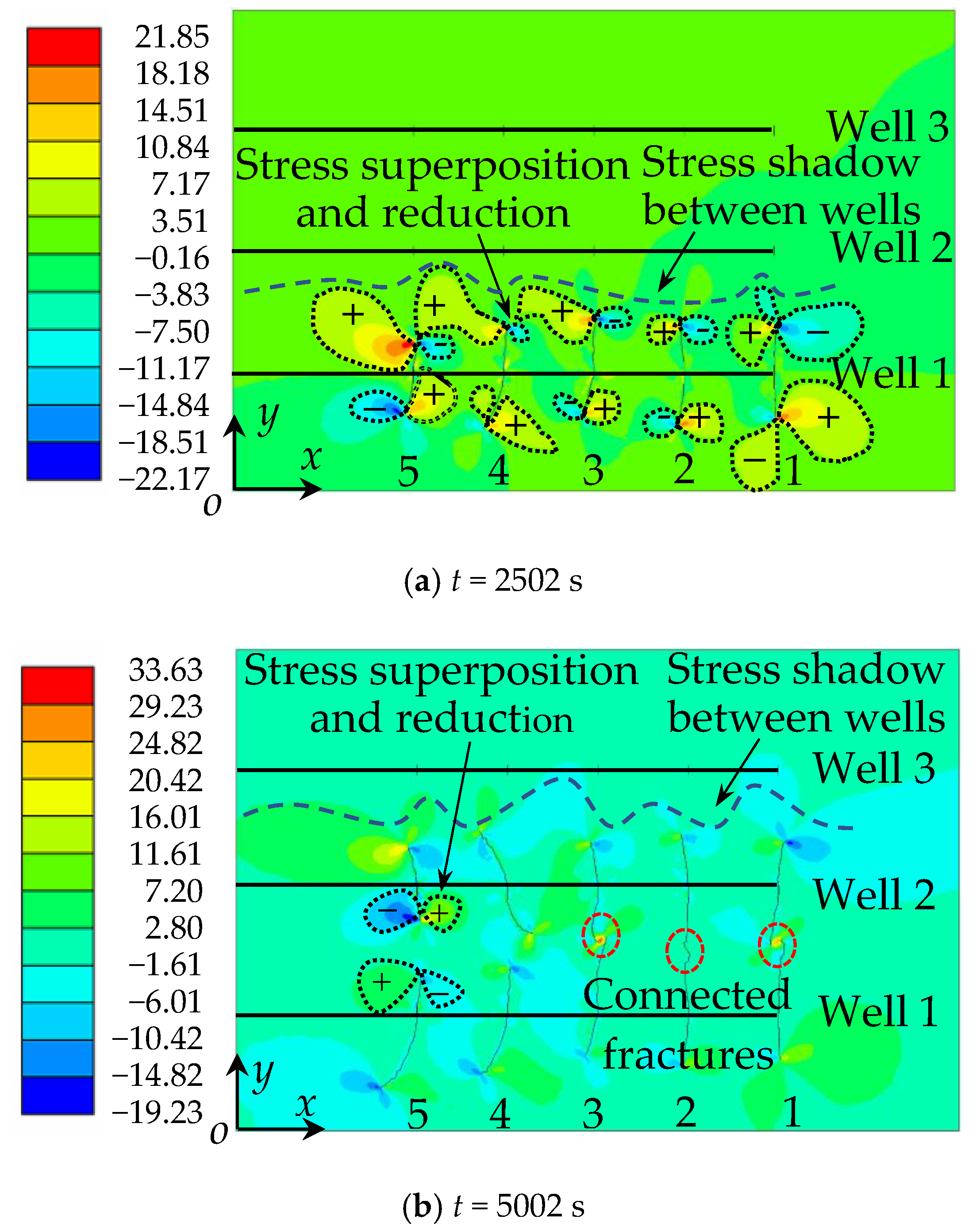
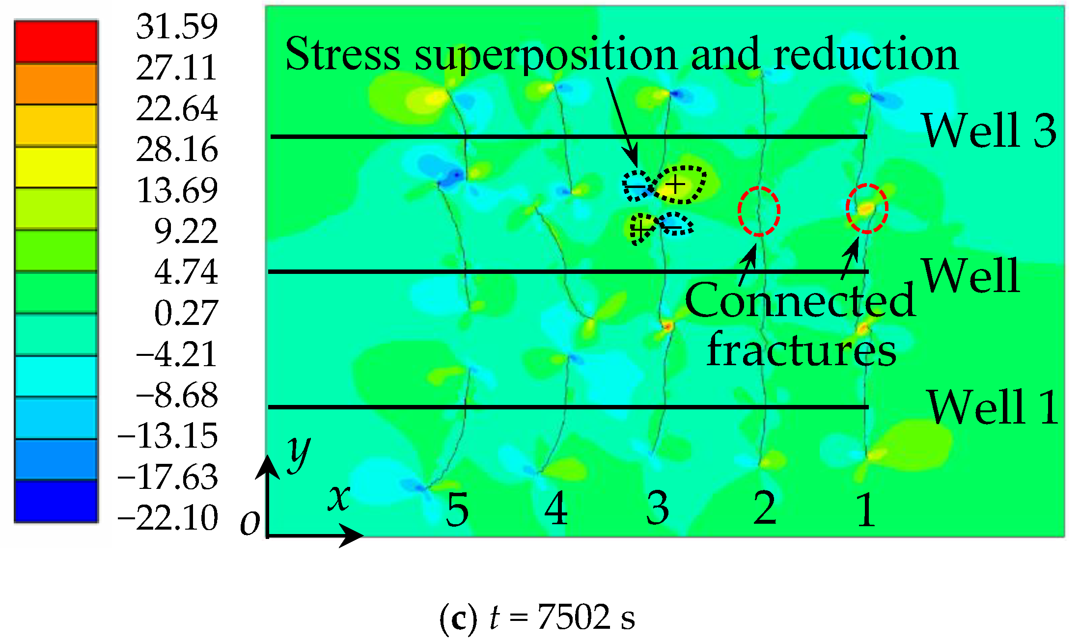
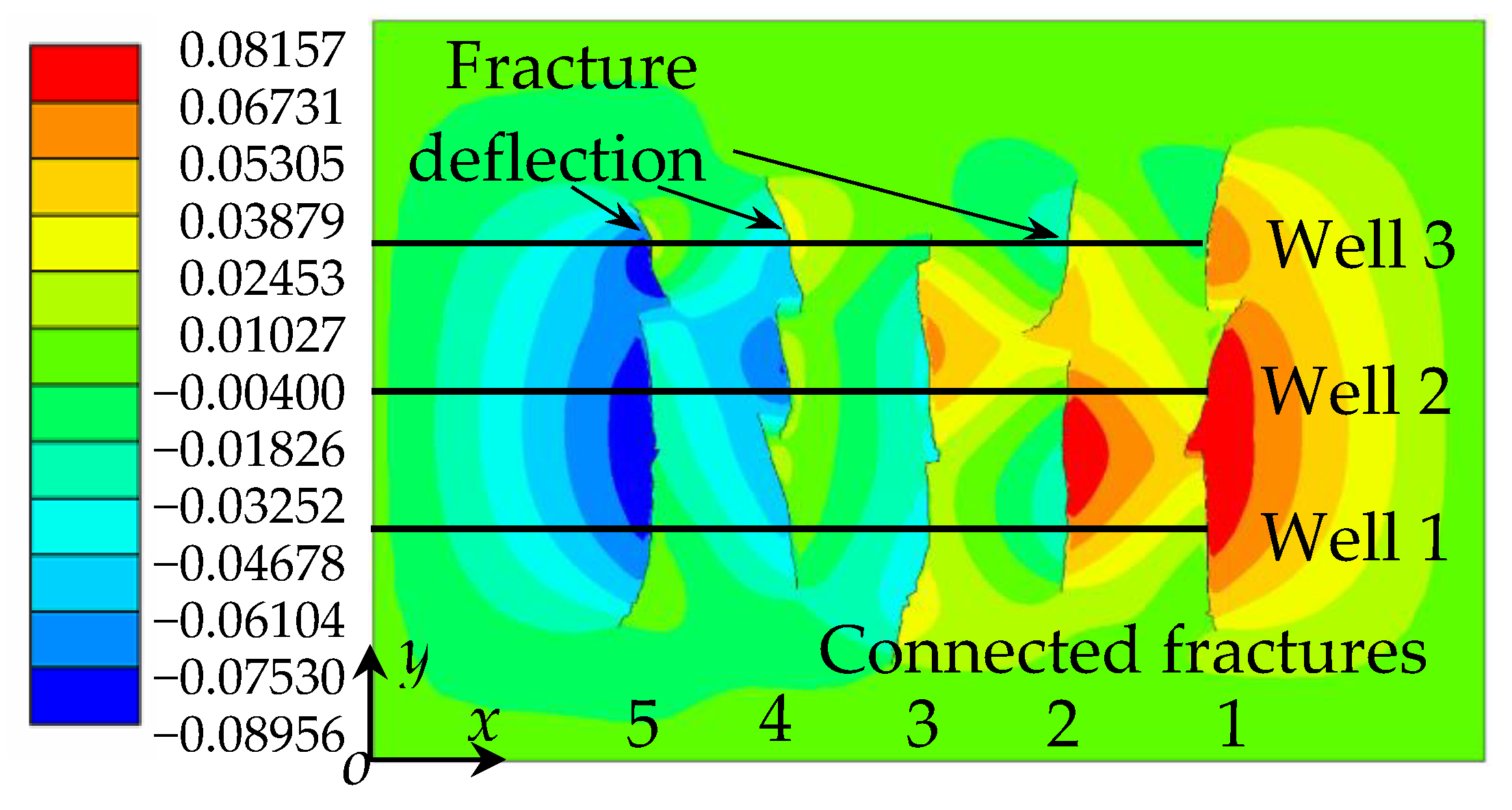
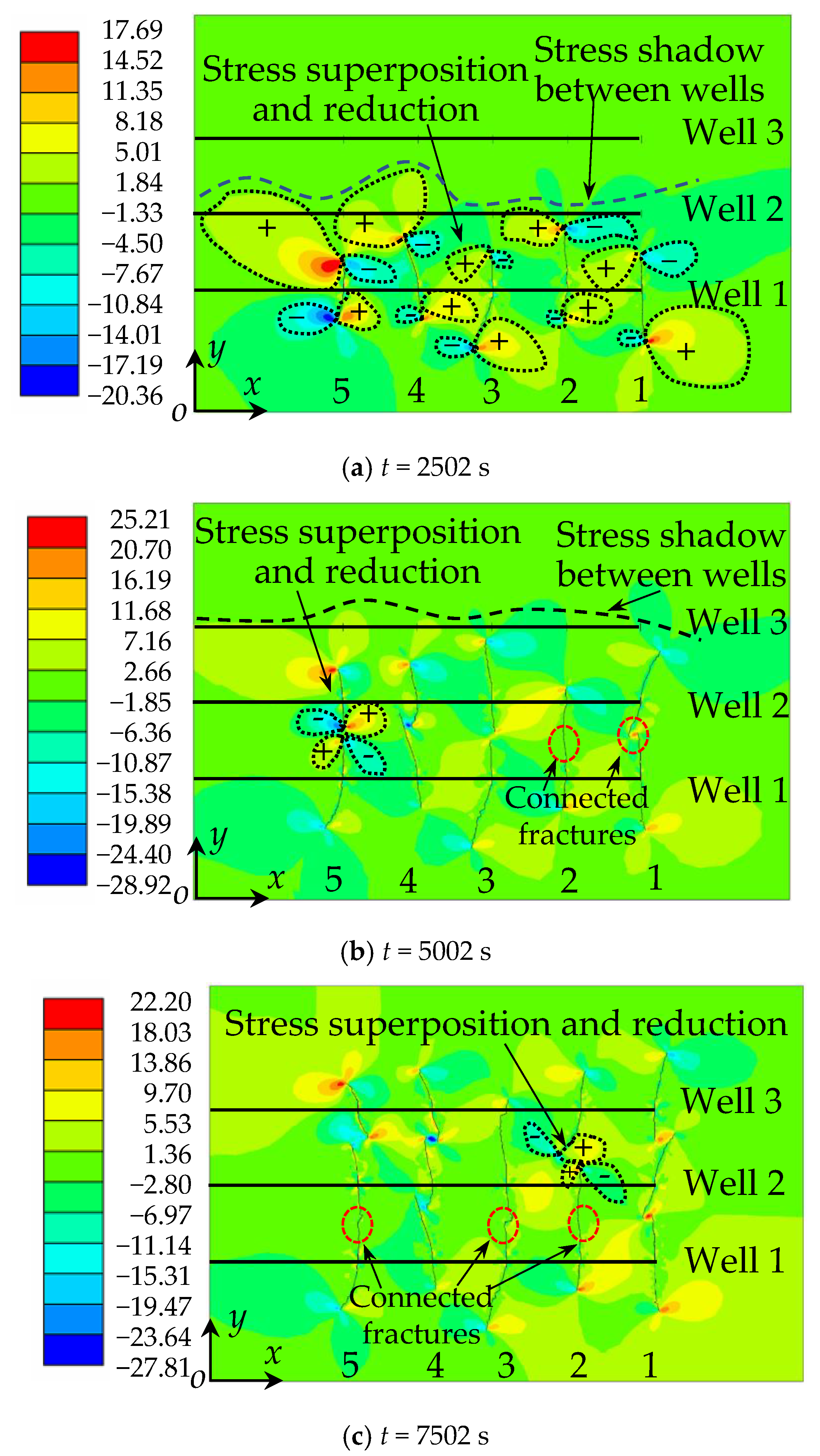
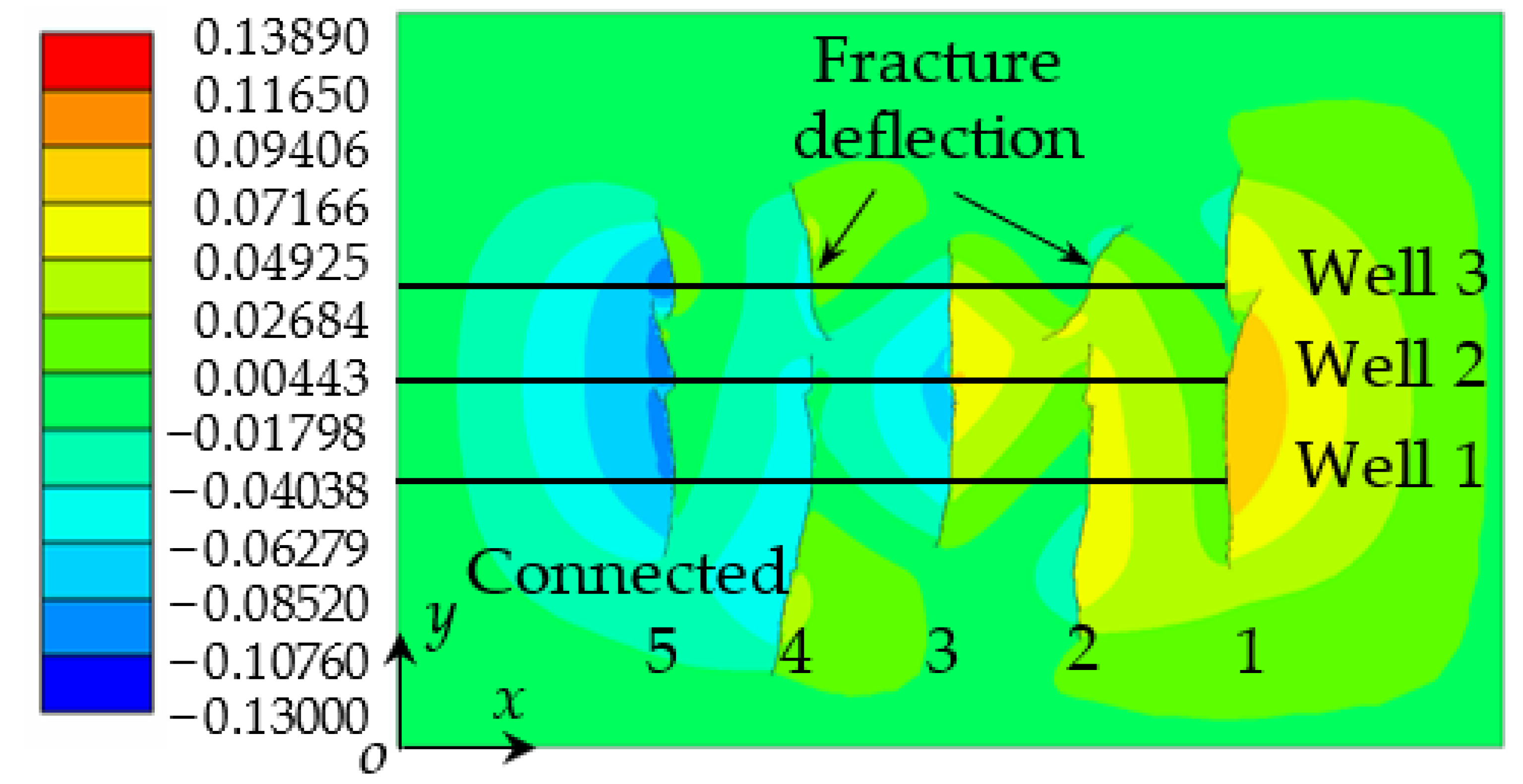
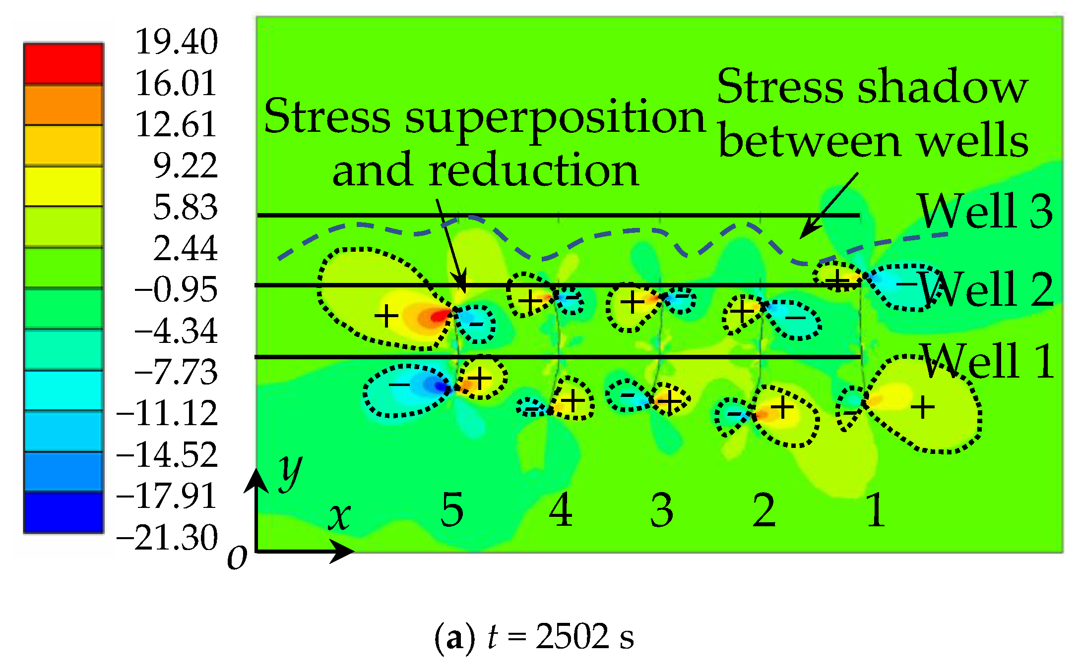
4.2. Fracture Network Propagation and Shear Stress Shadows
4.2.1. Case I: Well Spacing b = 100 m
4.2.2. Case II: Well Spacing b = 75 m
4.2.3. Case III: Well Spacing b = 50 m
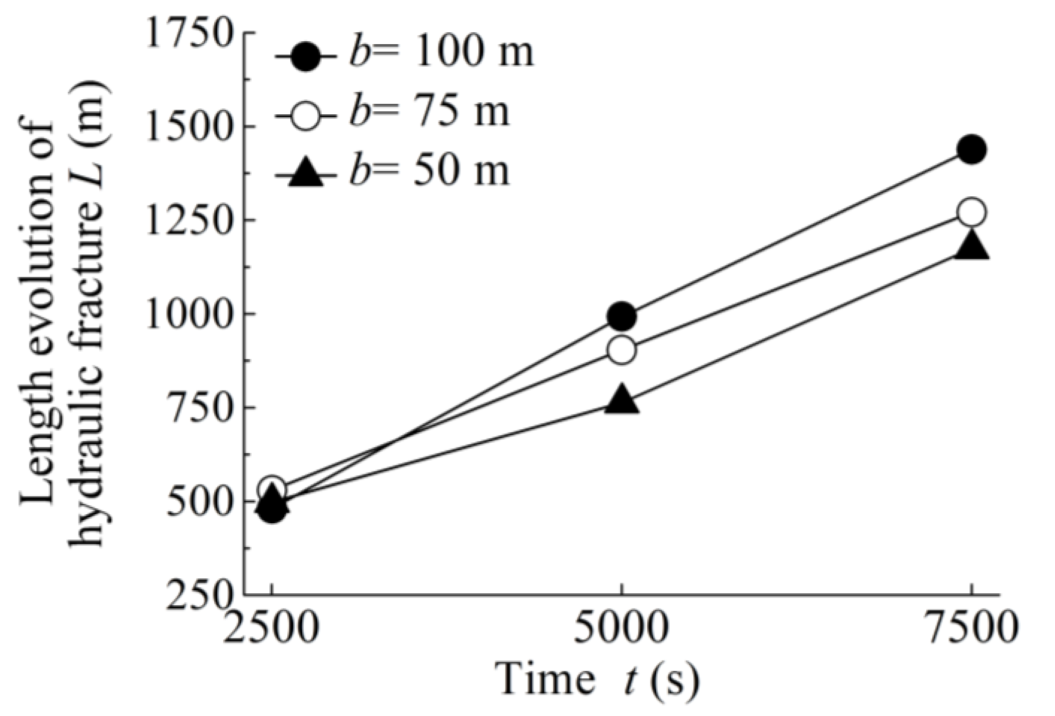
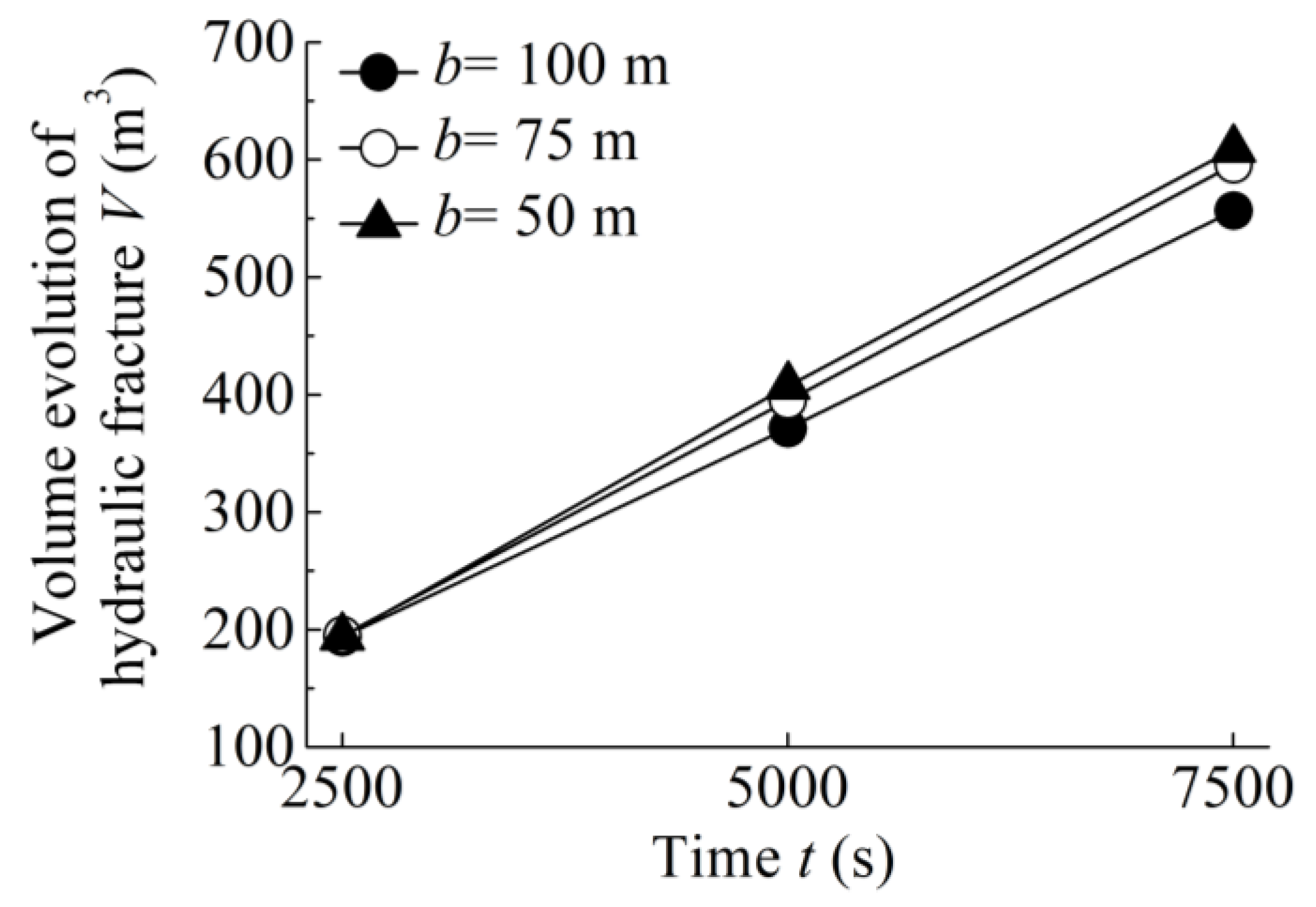
4.3. Quantitative Analysis of Fracture Length and Volume
5. Conclusions
- In multi-well hydrofracturing, the stress around the fracture interferes with adjacent fractures in adjacent wells. The shear stress fields around the fractures of horizontal wells are superimposed, and the fractures are deflected to the side with the larger shear stress; multi-well hydrofracturing will lead to fracture connectivity between wells;
- Varying well spacing will affect the unstable propagation of hydraulic fractures. With the decrease of well spacing, the disturbance of the stress field and the stress shadow area between wells gradually increase, the number of connected fractures also increases, the propagation length of the connected fractures gradually decreases and the unconnected fractures deflect. The degree of deflection increases and well spacing becomes an important factor affecting fracture propagation in multi-well hydrofracturing;
- In the quantitative analysis of the length and volume of fracture networks, the total length of hydraulic fractures decreases with the decrease of well spacing, and the total volume of hydraulic fractures increases with the decrease of well spacing. When the well spacing is set to 75 m under the field conditions in this study, a larger total length and volume of fracture propagation can be obtained.
Author Contributions
Funding
Institutional Review Board Statement
Informed Consent Statement
Data Availability Statement
Acknowledgments
Conflicts of Interest
References
- Wang, T.; Tian, S.; Zhang, W.; Ren, W.; Li, G. Production model of a fractured horizontal well in shale gas reservoirs. Energy Fuels 2020, 35, 493–500. [Google Scholar] [CrossRef]
- Olson, J.E.; Taleghani, A.D. Modeling simultaneous growth of multiple hydraulic fractures and their interaction with natural fractures. In Proceedings of the SPE Hydraulic Fracturing Technology Conference, The Woodlands, TX, USA, 19–21 January 2009. [Google Scholar] [CrossRef]
- Bunger, A.P.; Jeffrey, R.G.; Kear, J.; Zhang, X.; Morgan, M. Experimental investigation of the interaction among closely spaced hydraulic fractures. In Proceedings of the 45th U.S. Rock Mechanics/Geomechanics Symposium, San Francisco, CA, USA, 26–29 June 2011. [Google Scholar] [CrossRef]
- Bunger, A.P.; Zhang, X.; Jeffrey, R.G. Parameters affecting the interaction among closely spaced hydraulic fractures. SPE J. 2012, 17, 292–306. [Google Scholar] [CrossRef]
- He, Q.Y.; Suorineni, F.T.; Ma, T.H.; Oh, J. Effect of discontinuity stress shadows on hydraulic fracture re-orientation. Int. J. Rock Mech. Min. 2017, 91, 179–194. [Google Scholar] [CrossRef]
- Manriquez, A.L. Stress behavior in the near fracture region between adjacent horizontal wells during multistage fracturing using a coupled stress-displacement to hydraulic diffusivity model. J. Petrol. Sci. Eng. 2018, 162, 822–834. [Google Scholar] [CrossRef]
- Noii, N.; Fan, M.; Wick, T.; Jin, Y. A quasi-monolithic phase-field description for orthotropic anisotropic fracture with adaptive mesh refinement and primal–dual active set method. Eng. Fract. Mech. 2021, 258, 108060. [Google Scholar] [CrossRef]
- Xia, L.; Yvonnet, J.; Ghabezloo, S. Phase field modeling of hydraulic fracturing with interfacial damage in highly heterogeneous fluid-saturated porous media. Eng. Fract. Mech. 2017, 186, 158–180. [Google Scholar] [CrossRef] [Green Version]
- Roussel, N.P.; Sharma, M.M. Optimizing fracture spacing and sequencing in horizontal-well fracturing. SPE Prod. Oper. 2011, 26, 173–184. [Google Scholar] [CrossRef]
- Nagel, N.; Zhang, F.; Sanchez-Nagel, M.; Lee, B.; Agharazi, A. Stress shadow evaluations for completion design in unconventional plays. In Proceedings of the SPE Unconventional Resources Conference Canada, Calgary, AB, Canada, 5–7 November 2013. [Google Scholar] [CrossRef]
- Manchanda, R.; Sharma, M.M. Impact of completion design on fracture complexity in horizontal shale wells. SPE Drill. Completion 2014, 29, 78–87. [Google Scholar] [CrossRef]
- Wu, K.; Olson, J.E. Simultaneous multifracture treatments: Fully coupled fluid flow and fracture mechanics for horizontal wells. SPE J. 2015, 20, 337–346. [Google Scholar] [CrossRef]
- Bai, T.; Pollard, D.D.; Gao, H. Explanation for fracture spacing in layered materials. Nature 2000, 403, 753–756. [Google Scholar] [CrossRef]
- Warpinski, N.R. Analytic crack solutions for tilt fields around hydraulic fractures. J. Geophys. Res.-Solid Earth 2020, 105, 23463–23478. [Google Scholar] [CrossRef] [Green Version]
- Sobhaniaragh, B.; Mansur, W.J.; Peters, F.C. The role of stress interference in hydraulic fracturing of horizontal wells. Int. J. Coal Sci. Technol. 2018, 106, 153–164. [Google Scholar] [CrossRef]
- Lu, C.; Guo, J.C.; Liu, Y.X.; Yin, J.; Deng, Y.; Lu, Q.L.; Zhao, X. Perforation spacing optimization for multi-stage hydraulic fracturing in Xujiahe formation: A tight sandstone formation in Sichuan Basin of China. Environ. Earth Sci. 2015, 73, 5843–5854. [Google Scholar] [CrossRef]
- Tian, W.; Li, P.; Dong, Y.; Lu, Z.; Lu, D. Numerical simulation of sequential, alternate and modified zipper hydraulic fracturing in horizontal wells using XFEM. J. Petrol. Sci. Eng. 2019, 183, 106251. [Google Scholar] [CrossRef]
- Wang, Y.; Li, X.; Wang, J.B.; Zheng, B.; Zhang, B.; Zhao, Z.H. Numerical modeling of stress shadow effect on hydraulic fracturing. Nat. Gas Geosci. 2015, 26, 1941–1950. [Google Scholar]
- Ghazal, I.; Michael, G.; Leonardo, C.; Christine, B.; Daniel, M.; Fu, P. Fully 3D hydraulic fracturing model: Optimizing sequence fracture stimulation in horizontal wells. In Proceedings of the 49th U.S. Rock Mechanics/Geomechanics Symposium, San Francisco, CA, USA, 28 June–1 July 2015; p. ARMA-2015-119. [Google Scholar]
- Kumar, D.; Ghassemi, A. A three-dimensional analysis of simultaneous and sequential fracturing of horizontal wells. J. Petrol. Sci. Eng. 2016, 146, 1006–1025. [Google Scholar] [CrossRef]
- Ju, Y.; Li, Y.; Wang, Y.L.; Yang, Y. Stress shadow effects and microseismic events during hydrofracturing of multiple vertical wells in tight reservoirs: A three-dimensional numerical model. J. Nat. Gas Sci. Eng. 2020, 84, 103684. [Google Scholar] [CrossRef]
- Wong, S.W.; Geilikman, M.; Xu, G. Interaction of multiple hydraulic fractures in horizontal wells. In Proceedings of the SPE Unconventional Gas Conference and Exhibition, Muscat, Oman, 28–30 January 2013. [Google Scholar] [CrossRef] [Green Version]
- Segatto, M.; Colombo, I. Use of reservoir simulation to help gas shale reservoir estimation. In Proceedings of the International Petroleum Technology Conference (IPTC’11), Bangkok, Thailand, 15–17 November 2011. [Google Scholar] [CrossRef]
- Liu, X.; Rasouli, V.; Guo, T.; Qu, Z.; Sun, Y.; Damjanac, B. Numerical simulation of stress shadow in multiple cluster hydraulic fracturing in horizontal wells based on lattice modelling. Eng. Fract. Mech. 2020, 238, 107278. [Google Scholar] [CrossRef]
- Li, S.; Zhang, D. A fully coupled model for hydraulic-fracture growth during multiwell-fracturing treatments: Enhancing fracture complexity. SPE Prod. Oper. 2018, 33, 235–250. [Google Scholar] [CrossRef]
- He, Y.; Yang, Z.; Li, X.; Song, R. Numerical simulation study on three-dimensional fracture propagation of synchronous fracturing. Energy Sci. Eng. 2020, 8, 944–958. [Google Scholar] [CrossRef] [Green Version]
- Duan, K.; Li, Y.C.; Yang, W.D. Discrete element method simulation of the growth and efficiency of multiple hydraulic fractures simultaneously-induced from two horizontal wells. Geomech. Geophys. Geo. 2021, 7, 3. [Google Scholar] [CrossRef]
- Wu, K.; Wu, B.; Yu, W. Mechanism analysis of well interference in unconventional reservoirs: Insights from fracture-geometry simulation between two horizontal wells. SPE Prod. Oper. 2018, 33, 12–20. [Google Scholar] [CrossRef]
- Jo, H. Optimizing fracture spacing to induce complex fractures in a hydraulically fractured horizontal wellbore. In Proceedings of the SPE Americas Unconventional Resources Conference, Pittsburgh, PA, USA, 5–7 June 2012. [Google Scholar] [CrossRef]
- Manchanda, R.; Sharma, M.M. Time-delayed fracturing: A new strategy in multi-stage, multi-well pad fracturing. In Proceedings of the SPE Annual Technical Conference and Exhibition, New Orleans, LA, USA, 30 September–2 October 2013. [Google Scholar] [CrossRef]
- Wu, K.; Olson, J.E. Numerical investigation of complex hydraulic-fracture development in naturally fractured reservoirs. SPE Prod. Oper. 2016, 31, 300–309. [Google Scholar] [CrossRef]
- Tsang, C.F.; Stephansson, O.; Hudson, J.A. A discussion of thermos-hydro-mechanical (THM) processes associated with nuclear waste repositories. Int. J. Rock Mech. Min. 2000, 37, 397–402. [Google Scholar] [CrossRef]
- Rutqvist, J.; Barr, D.; Datta, R.; Gens, A.; Millard, A.; Olivella, S.; Tsang, C.F.; Tsang, Y. Coupled thermal–hydrological–mechanical analyses of the Yucca Mountain Drift Scale Test—Comparison of field measurements to predictions of four different numerical models. Int. J. Rock Mech. Min. 2005, 42, 680–697. [Google Scholar] [CrossRef] [Green Version]
- Wang, Y.; Ju, Y.; Chen, J.; Song, J. Adaptive finite element–discrete element analysis for the multistage supercritical CO2 fracturing and microseismic modelling of horizontal wells in tight reservoirs considering pre-existing fractures and thermal-hydro-mechanical coupling. J. Nat. Gas Sci. Eng. 2019, 61, 251–269. [Google Scholar] [CrossRef]
- Wang, Y.; Ju, Y.; Yang, Y. Adaptive finite element-discrete element analysis for microseismic modelling of hydraulic fracture propagation of perforation in horizontal well considering pre-existing fractures. Shock Vib. 2018, 2018, 1–14. [Google Scholar] [CrossRef]
- Wang, Y.L. Adaptive finite element–discrete element analysis for stratal movement and microseismic behaviours induced by multistage propagation of three-dimensional multiple hydraulic fractures. Eng. Comput. 2020, 38, 2781–2809. [Google Scholar] [CrossRef]
- Wang, Y.L.; Liu, X.G. Stress-dependent unstable dynamic propagation of three-dimensional multiple hydraulic fractures with improved fracturing sequences in heterogeneous reservoirs: Numerical cases study via poroelastic effective medium model. Energy Fuels 2021, 35, 18543–18562. [Google Scholar] [CrossRef]
- Inui, S.; Ishida, T.; Nagaya, Y.; Nara, Y.; Chen, Y.; Chen, Q. AE monitoring of hydraulic fracturing experiments in granite blocks using supercritical CO2, water and viscous oil. In Proceedings of the 48th U.S. Rock Mechanics/Geomechanics Symposium, Minneapolis, MN, USA, 1–4 June 2014; p. ARMA-2014-7163. [Google Scholar]
- Wang, Y.; Ju, Y.; Zhang, H.; Gong, S.; Song, J.; Li, Y.; Chen, J. Adaptive finite element–discrete element analysis for the stress shadow effects and fracture interaction behaviours in three-dimensional multistage hydrofracturing considering varying perforation cluster spaces and fracturing scenarios of horizontal wells. Rock Mech. Rock Eng. 2021, 54, 1815–1839. [Google Scholar] [CrossRef]


| Case | a (m) | b (m) | Fracturing Fluid Temperature (°C) | Rock Matrix Temperature (°C) |
|---|---|---|---|---|
| I | 75 | 100 | 20 | 60 |
| II | 75 | 75 | 20 | 60 |
| III | 75 | 50 | 20 | 60 |
| Parameters | Value |
|---|---|
| (MPa) | 40 |
| (MPa) | 44 |
| Fluid injection rate Q (m3/s) | 0.5 |
| Pore pressure (MPa) | 10 |
| 0.75 | |
| Elastic modulus E (GPa) | 31 |
| 0.22 | |
| Penetration k (nD) | 50 |
| 0.05 | |
| ) | 1.67 × 10⁻³ |
| (MPa) | 2000 |
| (MPa) | 5.26 |
| ) | 165 |
| b (m) | Time t (s) | Fracture Length L (m) | Fracture Volume V (m3) |
|---|---|---|---|
| 100 | Stage 1 (t = 2502 s) | 480.76 | 193.58 |
| 75 | 529.62 | 195.12 | |
| 50 | 498.00 | 193.73 | |
| 100 | Stage 2 (t = 5002 s) | 992.45 | 371.39 |
| 75 | 903.94 | 395.10 | |
| 50 | 763.11 | 407.22 | |
| 100 | Stage 3 (t = 7502 s) | 1438.69 | 556.38 |
| 75 | 1271.25 | 595.70 | |
| 50 | 1174.75 | 608.84 |
Publisher’s Note: MDPI stays neutral with regard to jurisdictional claims in published maps and institutional affiliations. |
© 2022 by the authors. Licensee MDPI, Basel, Switzerland. This article is an open access article distributed under the terms and conditions of the Creative Commons Attribution (CC BY) license (https://creativecommons.org/licenses/by/4.0/).
Share and Cite
Wang, Y.; Liu, N. Dynamic Propagation and Shear Stress Disturbance of Multiple Hydraulic Fractures: Numerical Cases Study via Multi-Well Hydrofracturing Model with Varying Adjacent Spacings. Energies 2022, 15, 4621. https://doi.org/10.3390/en15134621
Wang Y, Liu N. Dynamic Propagation and Shear Stress Disturbance of Multiple Hydraulic Fractures: Numerical Cases Study via Multi-Well Hydrofracturing Model with Varying Adjacent Spacings. Energies. 2022; 15(13):4621. https://doi.org/10.3390/en15134621
Chicago/Turabian StyleWang, Yongliang, and Nana Liu. 2022. "Dynamic Propagation and Shear Stress Disturbance of Multiple Hydraulic Fractures: Numerical Cases Study via Multi-Well Hydrofracturing Model with Varying Adjacent Spacings" Energies 15, no. 13: 4621. https://doi.org/10.3390/en15134621
APA StyleWang, Y., & Liu, N. (2022). Dynamic Propagation and Shear Stress Disturbance of Multiple Hydraulic Fractures: Numerical Cases Study via Multi-Well Hydrofracturing Model with Varying Adjacent Spacings. Energies, 15(13), 4621. https://doi.org/10.3390/en15134621