
Design of Cement–Slag Concrete Composition for 3D Printing


Abstract
:1. Introduction
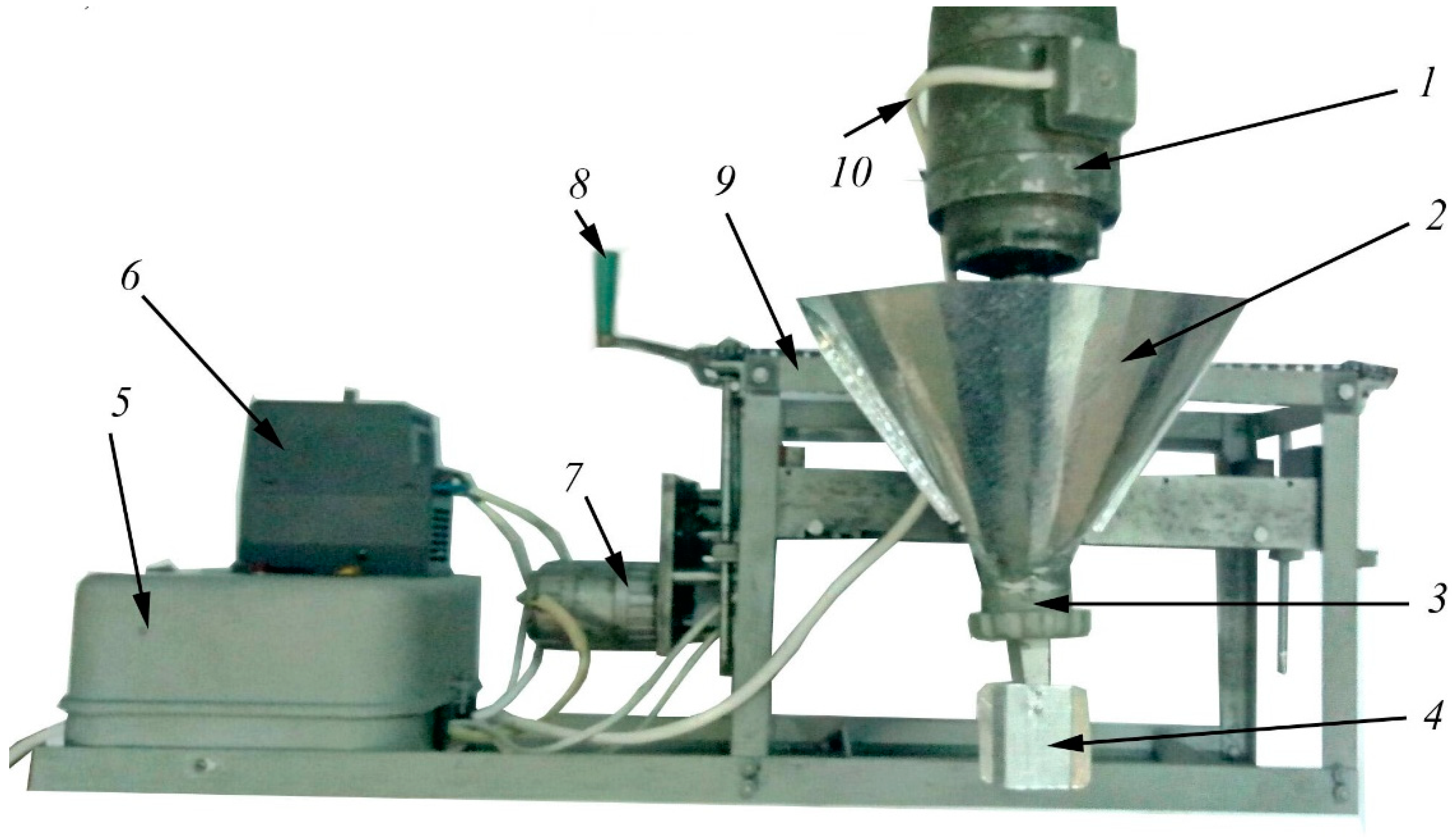
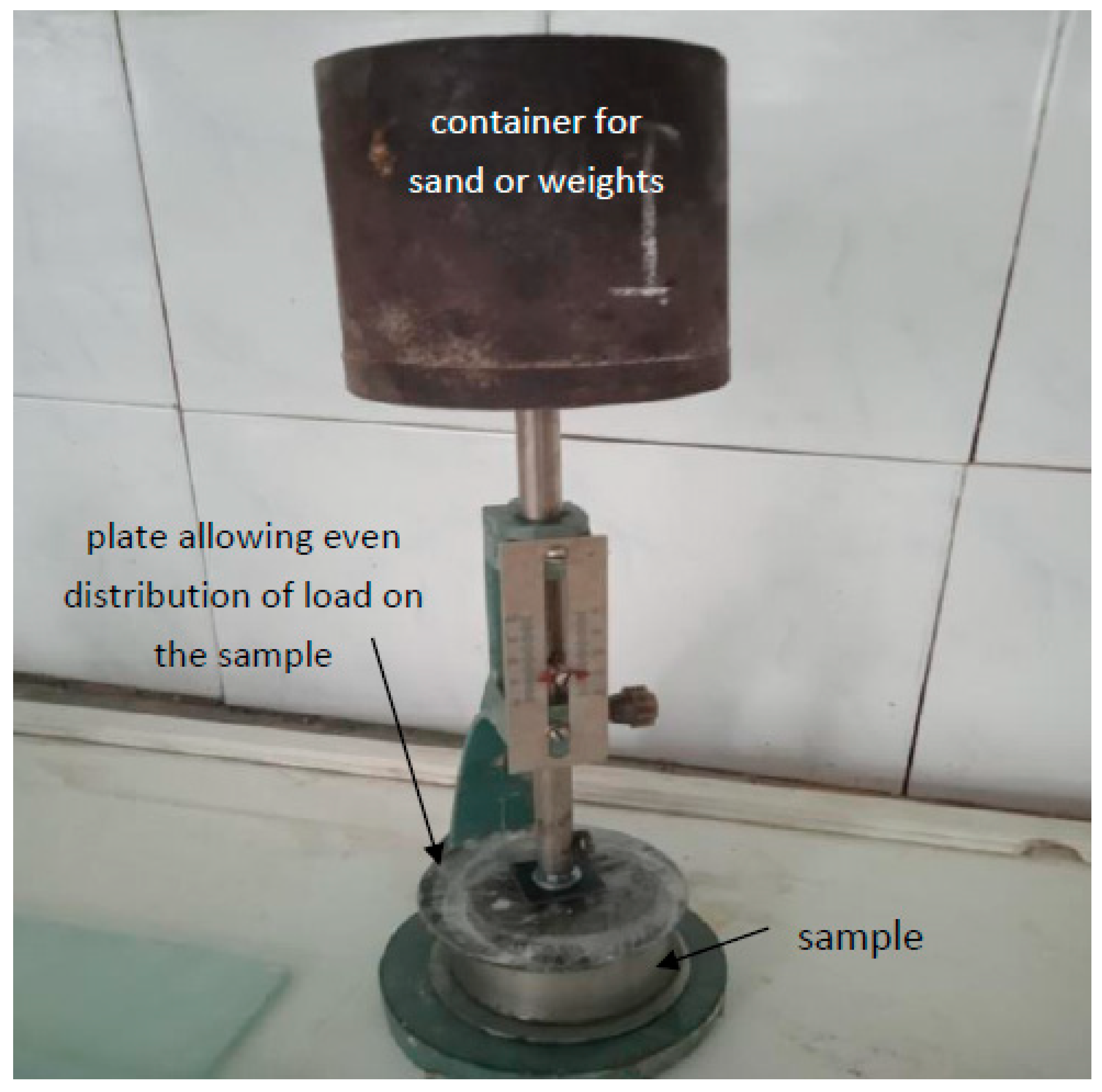
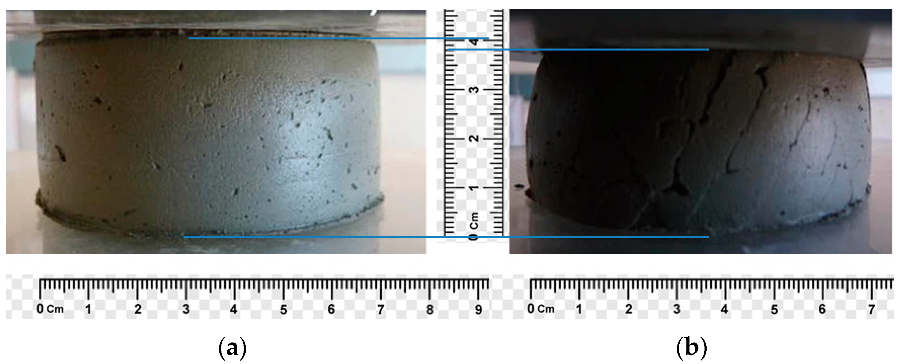
2. Materials and Methods of Research
3. Results and Discussion
| Setting time | HA > Bnd > GBFS |
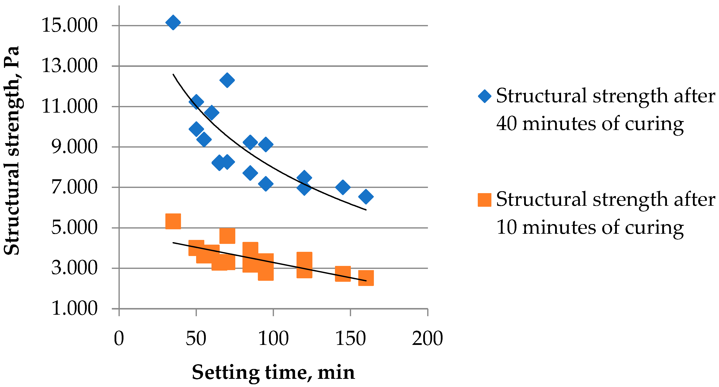
| Structural strength after 10 min of curing | Bnd > HA > GBFS |
| Structural strength after 25 min of curing | HA > Bnd > GBFS |
| Structural strength after 40 min of curing | HA > Bnd > GBFS |
| Compressive strength at the age of 3 days | Bnd > GBFS > HA |
| Splitting tensile strength at the age of 28 days | Bnd > GBFS >> HA |
| Compressive strength at the age of 28 days | Bnd > GBFS >> HA |
P2 ≥ f (x1, x2, …, xn);
…
Pm ≥ f (x1, x2, …, xn)
- Ctcm, Ctcem, CtGBFS, CtAd, CtS—cost of the concrete mixture, cement, blast-furnace granulated slag, chemical additives and sand, respectively, USD/kg;
- Cem, GBFS, Ad, S—amount of cement, slag, chemical additives and sand, kg/m3;
- P1…Pm—specified quality indicators of the mixture and concrete based on it;
- x1…xn—factors of the mixture composition considered in the models;
- a, b—limits on the possible values of the factors.
Example
- Using experimental–statistical models (1)–(7) and substituting values of normalized parameters into them, the functions of restrictions (9) are obtained:
- 2.
- In Equation (8), substitute the value of the cost of the components of the mixture, and set the limit values of the factors: from −1 to 1 (in coded form).
- 3.
- Using the “Search for a solution” software application, determine the values of the factors that satisfy the accepted constraints of the problem, and minimize the total cost of the mixture:x1 = 0.62; x2 = 0; x3 = 0.9.
- 4.
- Values of the factors in natural form are determined by Equation (10):Bnd = 0.9x3 + 100 = 0.9 × 100 + 400 = 490 kg/m3
GBFS = 0.62x1 + 10 = 0.62 × (−10) + 40 = 33.8%
HA = 0x2 + 1 = 0 × 0 + 1 = 1%
GBFS = 490 × 0.338 = 166 kg/m3
Cem = 490 − 166 = 324 kg/m3
HA = 0.01 × 490 = 4.9 kg/m3
SP = 490 × 0.003 = 1.47 kg/m3
- 5.
- Sand consumption from Equation (11):
- 6.
- The value of the minimum possible cost of 1 m3 of mixture without taking into account the cost of water (found by iterating with the program application “Search for a solution”):Ctcm = 0.28 × 324 + 0.02 × 166 + 4.9 × 2 + 1.47 × 3.2 + 1580 × 0.01 = 124.35$
4. Conclusions
- A set of mathematical models describing the effect of composition factors on the most important properties of fine-grained concrete mixture and concrete on cement–slag binder in the presence of hardening accelerator additive was obtained by using mathematical planning of experiments.
- As a result of the analysis of the obtained models, the nature and quantitative estimates of the mutual influence of concrete composition factors on the studied properties were established. Composition factors were ranked depending on the intensity of their influence.
- The relationships between structural strength and setting time, as well as various strength indicators of concrete produced on a 3D printer, were established for different values of mixture composition factors.
- The use of a binder containing 30…40% of ground-granulated blast-furnace slag and of hardening accelerator–sodium sulfate in the amount of 1…2% by weight of the binder allows obtaining mixtures suitable for 3D printing.
- The increased content of hardening accelerator–Na2SO4 leads to an increase in the compressive strength and splitting of concrete, as well as structural strength. An increase in the slag content of more than 40% is accompanied by a slight increase in the water consumption of the mixture to ensure the required extrusion possibility and a decrease in strength.
- Using mathematical programming implemented by Microsoft Excel and its “Search for a solution” application, the possibility of solving the problem of designing optimal compositions of construction mixtures used by a 3D printer was shown, based on the complex of experimental and statistical models.
Author Contributions
Funding
Data Availability Statement
Conflicts of Interest
References
- Perrot, A.; Rangeard, D.; Courtaille, E. 3D printing of earth-based materials: Processing aspects. Constr. Build. Mater. 2018, 172, 670–676. [Google Scholar] [CrossRef]
- Kaszynska, M.; Hoffmann, M.; Skibicki, S.; Zielinski, A.; Technan, M.; Olczyk, N.; Wroblewski, T. Evaluation of suitability for 3D printing of high performance concretes. In Proceedings of the MATBUD’2018—8th Scientific-Technical Conference on Material Problems in Civil Engineering, Szczecin, Poland, 15 June 2018; Volume 163. [Google Scholar] [CrossRef]
- Ali, M.H.; Issayev, G.; Shehab, E.; Sarfraz, S. A critical review of 3D printing and digital manufacturing in construction engineering. Rapid Prototyp. J. 2022. [Google Scholar] [CrossRef]
- Xu, T.; Shen, W.; Lin, X.; Xie, Y.M. Additively manufactured thermoplastic polyurethane (TPU) mold for concrete casting of complex structure. Rapid Prototyp. J. 2022. [Google Scholar] [CrossRef]
- Khorasani, M.; Ghasemi, A.; Rolfe, B.; Gibson, I. Additive manufacturing a powerful tool for the aerospace industry. Rapid Prototyp. J. 2022, 28, 87–100. [Google Scholar] [CrossRef]
- Le, T.T.; Austin, S.A.; Lim, S.; Buswell, R.A.; Gibb, A.G.F.; Thorne, T. Hardened properties of high-performance printing concrete. Cem. Concr. Res. 2012, 42, 558–566. [Google Scholar] [CrossRef] [Green Version]
- Inozemtcev, A.S.; Korolev, E.V.; Duong, T.Q. Analiz suschestvuyuschikh tekhnologicheskikh resheniy 3D-pechati v stroitel’stve [Analysis of existing technological solutions of 3D-printing in construction]. Vestn. MGSU 2018, 13, 863–876. [Google Scholar] [CrossRef]
- Perrot, A. (Ed.) 3D Printing of Concrete: State of the Art and Challenges of the Digital Construction Revolution, 1st ed.; John Wiley & Sons Inc.: Hoboken, NJ, USA, 2019; 176p. [Google Scholar]
- Ibrahim, M. Estimating the sustainability returns of recycling construction waste from building projects. Sustain. Cities Soc. 2016, 23, 78–93. [Google Scholar] [CrossRef]
- Hager, I.; Golonka, A.; Putanowicz, R. 3D printing of buildings and building components as the future of sustainable construction. Procedia Eng. 2016, 151, 292–299. [Google Scholar] [CrossRef] [Green Version]
- Chen, L.; He, Y.; Yang, Y.; Niu, S.; Ren, H. The research status and development trend of additive manufacturing technology. Int. J. Adv. Manuf. Technol. 2017, 89, 3651–3660. [Google Scholar] [CrossRef]
- Secrieru, E.; Khodor, J.; Schrofl, C.; Mechtcherine, V. Formation of lubricating layer and flow type during pumping of cement-based materials. Constr. Build. Mater. 2018, 178, 507–517. [Google Scholar] [CrossRef]
- Ma, G.; Buswell, R.; Leal da Silva, W.R.; Wang, L.; Xu, J.; Jones, S.Z. Technology readiness: A global snapshot of 3D concrete printing and the frontiers for development. Cem. Concr. Res. 2022, 156, 106774. [Google Scholar] [CrossRef]
- Ilcan, H.; Sahin, O.; Kul, A.; Yildirim, G.; Sahmaran, M. Rheological properties and compressive strength of construction and demolition waste-based geopolymer mortars for 3D-Printing. Constr. Build. Mater. 2022, 328, 127114. [Google Scholar] [CrossRef]
- Bolte, G.; Zajac, M.; Skocek, J.; Haha, M.B. Development of composite cements characterized by low environmental footprint. J. Clean. Prod. 2019, 226, 503–514. [Google Scholar] [CrossRef]
- Miller, S.A.; John, V.M.; Pacca, S.A.; Horvath, A. Carbon dioxide reduction potential in the global cement industry by 2050. Cem. Concr. Res. 2018, 114, 115–124. [Google Scholar] [CrossRef]
- Sanjuán, M.Á.; Estévez, E.; Argiz, C. Carbon Dioxide Absorption by Blast-Furnace Slag Mortars in Function of the Curing Intensity. Energies 2019, 12, 2346. [Google Scholar] [CrossRef] [Green Version]
- Gruyaert, E.; Heede, P.; Belie, N. Carbonation of slag concrete: Effect of the cement replacement level and curing on the carbonation coefficient—Effect of carbonation on the pore structure. Cem. Concr. Compos. 2013, 35, 39–48. [Google Scholar] [CrossRef]
- Dvorkin, L.; Dvorkin, O.; Ribakov, Y. Mathematical Experiments Planning in Concrete Technology; Nova Science Publishers: New York, NY, USA, 2011; 173p. [Google Scholar]
- Dvorkin, L.; Bordiuzhenko, O.; Zhitkovsky, V.; Marchuk, V. Mathematical modeling of steel fiber reinforced concrete properties and selecting its effective composition. IOP Conf. Ser. Mater. Sci. Eng. 2019, 708, 012085. [Google Scholar] [CrossRef]


| No. | Developer | Materials | Density, kg/m3 | Strength MPa | Technology Benefits | Technology Disadvantages | |
|---|---|---|---|---|---|---|---|
| In Splitting | In Compression | ||||||
| 1 | Win Sun (China) | Cement–sand mixture with demolition waste, fiberglass and special additives | 2000–2200 | 8.2 | 34.5 | Used products of processing building materials, micro-reinforcement | Requires large production areas and maintenance personnel, the presence of non-functional formwork |
| 2 | AMT-SPETSAVIA (Russia) | High-strength cement–sandy fiber reinforced | 2200–2350 | – | oт 30 | Micro-reinforcement, material variability | The presence of non-functional formwork, uneven vertical surface |
| 3 | Stroy Bot (3D Printer) | Geopolymer concrete with puzzolan admixtures | 2100–2250 | – | – | Use of local raw materials for concrete mixtures | Uneven vertical surface |
| 4 | Bet-Abram (Slovenia) | Shotcrete with sand (0–4 mm) and gravel (4–8 mm) aggregates | 2300–2350 | – | – | The presence of anti-shrink additives | Non-functional formwork |
| 5 | Contour Crafting Corp. (USA) | Cement mortar for formwork, concrete for structures | 2250 | – | 45–50 | Leveled vertical surface, reinforcement | Low strength between layers |
| 6 | Apis Cor (Russia) | Fine-grained fiber reinforced concrete | 2050 | – | 27.4 | Micro-reinforcement | Uneven vertical surface, height limit 3.3 m |
| 7 | Loughborough University (Geat Britain) | Cement concrete | 2250–2350 | 12–13 | 100–110 | High strength, reinforcement structures. | Uneven vertical surface |
| 8 | CyBe Construction (The Netherlands) | Cement concrete | 2200 | 6 | 45 | Leveled vertical surface, fast setting and hardening of layers. | Unsynchronized mix feed and printer head movement |
| 9 | Batiprint 3D (France) | Polyurethane formwork filled with concrete | 30 | – | 0.16 | The formwork performs a heat-insulating function | Uncontrolled geometric parameters of structures, uneven vertical surface that needs protection from external influences |
| 10 | MIT Media Lab (USA) | Polyurethane formwork filled with concrete | – | – | – | The mobility of the extruder, the formwork performs the thermal insulation function of structures | |
| 11 | DUS Architects (The Netherlands) | Recycled plastic for formwork, lightweight concrete | – | – | – | Used secondary raw materials | The duration of the formwork manufacturing process |
| Name Material | L.O.I. | Oxide Content, % | ||||||||
|---|---|---|---|---|---|---|---|---|---|---|
| SiO2 | Al2O3 | Fe2O3 | CaO | MgO | SO3 | K2O | Na2O | TiO2 | ||
| Clinker | - | 21.80 | 5.32 | 4.11 | 66.80 | 0.95 | 0.63 | 0.54 | 0.42 | - |
| Blast-furnace slag | 0.59 | 39.51 | 6.47 | 0.14 | 47.19 | 3.12 | 1.76 | - | 0.25 | |
| Technological Factors | Levels of Variation | Variation Interval | |||
|---|---|---|---|---|---|
| natural view | coded view | −1 | 0 | +1 | data |
| Content of granulated blast furnace slag in the binder mixture (GBFS), % | X1 | 50 | 40 | 30 | −10 |
| Na2SO4 hardening accelerator additive content (HA), % of the binder mass | X2 | 0 | 1 | 2 | 1 |
| Cement–slag binder content, kg/m3, (Bnd) | X3 | 300 | 400 | 500 | 100 |
| No. | Setting Time, min | Structural Strength after Mixing and Hardening, Pa | Tensile Splitting Strength, MPa | Compressive Strength, MPa | ||||
|---|---|---|---|---|---|---|---|---|
| 10 min | 25 min | 40 min | 3 days | 28 days | 3 days | 28 days | ||
| 1 | 35 | 5320 | 8513 | 15,160 | 6.6 | 9.3 | 19.7 | 32.7 |
| 2 | 60 | 3780 | 5679 | 10,700 | 4.5 | 6.7 | 10.8 | 21.2 |
| 3 | 85 | 3916 | 5482 | 9225 | 5.7 | 8.1 | 16.9 | 27.6 |
| 4 | 145 | 2730 | 4096 | 7000 | 3.9 | 6.1 | 7.8 | 19.5 |
| 5 | 70 | 4600 | 6916 | 12,300 | 4.9 | 6.6 | 13.8 | 19.4 |
| 6 | 95 | 3356 | 5034 | 9125 | 4.1 | 5 | 8.8 | 13.4 |
| 7 | 120 | 3426 | 5139 | 7480 | 4.4 | 6.1 | 13.1 | 17.1 |
| 8 | 160 | 2521 | 3781 | 6545 | 3.5 | 4.8 | 7.8 | 9.4 |
| 9 | 55 | 3637 | 5455 | 9375 | 4.3 | 7.7 | 12.9 | 21.7 |
| 10 | 85 | 3177 | 4765 | 7710 | 3.6 | 5.1 | 10.6 | 16.4 |
| 11 | 50 | 4020 | 6030 | 11,230 | 4.7 | 6.5 | 12 | 20.5 |
| 12 | 120 | 2900 | 4350 | 6970 | 4.0 | 6.5 | 12.7 | 18.5 |
| 13 | 50 | 4002 | 6003 | 9880 | 6.3 | 8.7 | 17.8 | 28.5 |
| 14 | 95 | 2782 | 4173 | 7180 | 4.2 | 5.2 | 9.4 | 13.0 |
| 15 | 65 | 3275 | 4913 | 8240 | 5.0 | 7.2 | 10.9 | 21.7 |
| 16 | 70 | 3300 | 4950 | 8260 | 4.7 | 6.9 | 10.6 | 21.4 |
| 17 | 65 | 3310 | 4965 | 8200 | 4.9 | 7.1 | 10.8 | 21.6 |
| Parameters Studied | Mathematical Models | |
|---|---|---|
| Setting time, min | T = 66.4 − 15.0x1 − 32.0x2 − 19.5x3 + 4.1x12 + 19.1x22 + 6.6x32 − 2.5x1x2 − 2.5x1x3 + 6.3x2x3 | (1) |
| Structural strength after 10 min of curing, Pa | P10m = 3295 + 230x1 + 558x2 + 610x3 + 124x12 + 177x22 + + 108x32 + 55x1x2 +72x1x3 + 87x2x3 | (2) |
| Structural strength after 25 min of curing, Pa | P25m = 4938 + 359x1 +932x2 + 193x3 +273x12 + 171x22 x32 +∙198x1x2 ∙ +123x1x3 + 247x2x3 | (3) |
| Structural strength after 40 min of curing, Pa | P40m = 8258 + 830x1 + 2130x2 + 1350x3 + 296x12 + 853x22 + 283x32 + 280x1x2 + 322x1x3 + 560x2x3 | (4) |
| Compressive strength at the age of 3 days, MPa | f3cm = 11.66 + 1.4x1 + 0.68x2 + 3.67x3 − 0.54x12 + 0.06x22 + 1.31x32 + 0.51x1x2 + 0.96x1x3 − 0.06x2x3 | (5) |
| Splitting tensile strength at the age of 28 days, MPa | f28tn = 6.89 + 1.03x1 + 0.25x2 + 1.1x3 − 0.328x12 − 0.228x22 + + 0.222x32 + 0.138x1x2 + 0.213x1x3 + 0.113x2x3 | (6) |
| Compressive strength at the age of 28 days, MPa | f28cm = 20.74 + 4.7x1 + 1.51x2 + 4.88x3 − 1.01x12 − − 0.56x22 + 0.69x32 + 0.06x1x2 + 0.74x1x3 + 0.21x2x3 | (7) |
Publisher’s Note: MDPI stays neutral with regard to jurisdictional claims in published maps and institutional affiliations. |
© 2022 by the authors. Licensee MDPI, Basel, Switzerland. This article is an open access article distributed under the terms and conditions of the Creative Commons Attribution (CC BY) license (https://creativecommons.org/licenses/by/4.0/).
Share and Cite
Dvorkin, L.; Marchuk, V.; Hager, I.; Maroszek, M. Design of Cement–Slag Concrete Composition for 3D Printing. Energies 2022, 15, 4610. https://doi.org/10.3390/en15134610
Dvorkin L, Marchuk V, Hager I, Maroszek M. Design of Cement–Slag Concrete Composition for 3D Printing. Energies. 2022; 15(13):4610. https://doi.org/10.3390/en15134610
Chicago/Turabian StyleDvorkin, Leonid, Vitaliy Marchuk, Izabela Hager, and Marcin Maroszek. 2022. "Design of Cement–Slag Concrete Composition for 3D Printing" Energies 15, no. 13: 4610. https://doi.org/10.3390/en15134610
APA StyleDvorkin, L., Marchuk, V., Hager, I., & Maroszek, M. (2022). Design of Cement–Slag Concrete Composition for 3D Printing. Energies, 15(13), 4610. https://doi.org/10.3390/en15134610