Abstract
This work investigated the influence of the reaction time and catalyst-to-residual fat ratio by catalytic upgrading from pyrolysis vapors of residual fat at 400 °C and 1.0 atmosphere, on the yields of reaction products, physicochemical properties (density, kinematic viscosity, and acid value) and chemical composition of bio-oils, over a catalyst fixed-bed reactor of activated carbon pellets impregnated with 10.0 M NaOH, in semi-pilot scale. The experiments were carried out at 400 °C and 1.0 atmosphere, using a process schema consisting of a thermal cracking reactor of 2.0 L coupled to a catalyst fixed-bed reactor of 53 mL, without catalyst and using 5.0%, 7.5%, and 10.0% (wt.) activated carbon pellets impregnated with 10.0 M NaOH, in batch mode. Results show yields of bio-oil decreasing with increasing catalyst-to-tallow ratio. The GC-MS of liquid reaction products identified the presence of hydrocarbons (alkanes, alkenes, ring-containing alkanes, ring-containing alkenes, and aromatics) and oxygenates (carboxylic acids, ketones, esters, alcohols, and aldehydes). For all the pyrolysis and catalytic cracking experiments, the hydrocarbon selectivity in bio-oil increases with increasing reaction time, while those of oxygenates decrease, reaching concentrations of hydrocarbons up to 95.35% (area).
1. Introduction
In recent years, catalytic upgrading of lipid-base pyrolysis vapors over a catalyst fixed bed has been applied as an alternative process to deoxygenate bio-oils volatiles and produce liquid mixtures rich in hydrocarbons with superior transport and physicochemical properties, and the literature reports several studies on the subject [1,2,3,4,5,6,7,8,9,10,11,12,13].
Most studies on catalytic upgrade focused on the pyrolysis vapors of lipid-base materials including microalgae such as Chlorella vulgaris [1], Chromolaena odorata [2], Jatropha waste [3,4,5,6], soap stock [2,7,8], waste cooking oil [9,10], cottonseed oil dregs [11], tallow kernel oil [12], and castor seed oil [13].
The pyrolysis vapors of lipid-base materials chemically upgraded over catalyst supports including Ni/Y-zeolite [1], HZSM-5 [2,6,7,8,10], metal oxide (Ce, Pd, Ru, Ni) impregnated activated carbon [3], oxide-base catalysts [4,5,13], including aluminum (Al2O3, CeO2/Al2O3, Pd/CeO2/Al2O3, Ru/CeO2/Al2O3, Ni/CeO2/Al2O3), zirconia (ZrO2, CeO2/ZrO2, Pd/CeO2/ZrO2, Ru/CeO2/ZrO2, Ni/CeO2/ZrO2) and titania based catalysts (TiO2-R, TiO2-A, CeO2/TiO2-R, CeO2/TiO2-A ZrO2/TiO2, Pd/CeO2/TiO2-R, Ru/CeO2/TiO2-R, Ni/CeO2/TiO2-R, Pd/CeO2/TiO2-A, Ru/CeO2/TiO2-A, Ni/CeO2/TiO2-A) [4], CaO [5,13], ZnO [13], and kaolin [13], MCM-41 [8,12], HZSM-5/MCM-41 [8], metal oxide (Ca, Ce, Zr, Ni, Co) impregnated HZSM-5 (CaO/HZSM-5, CeO2/HZSM-5, ZrO2/HZSM-5, NiO/HZSM-5, CoO/HZSM-5) [9], metal impregnated (Co, Ni) HZSM-5 (Co/HZSM-5, Ni/HZSM-5), and Mo-Ni supported on γ-Al2O3 (α-Al2O3, γ-Al2O3, Mo-Co/γ-Al2O3, and Mo-Ni/γ-Al2O).
All the studies on catalytic upgrade of pyrolysis vapors from lipid-base materials focused on deoxygenation of bio-oil [1,2,3,4,5,6,7,8,9,10,11,12,13], but emphasis has also been given on the conversion of BTEXN (Benzene, Toluene, Ethyl-benzene, Xylene, Naphthalene) [3,6,9], as well as reaction mechanism/pathway [3,10,11,12]. The catalytic upgrade of pyrolysis volatiles has been carried out by flash pyrolysis/analytical pyrolysis (Py–GC/MS) [3,4,6], as well as by vacuum pyrolysis [7,9,11,12], in drop-tube/downdraft reactors [2,7,8,9,12], fixed-bed reactors [1,2,5,7,8,9,11,12,13], and fluidized-bed reactors [10]. The catalytic upgrade of pyrolysis vapors was performed at analytical [3,4,6], micro [1,11], and laboratory scales [2,5,7,8,9,10,12,13]. The catalytic upgrade processes operated in batch [1,3,4,6,13], and continuous mode [2,5,7,8,9,10,11,12], and only a few studies operated as a two-stage reactor, that is, using a process schema consisting of a thermal cracking reactor coupled to a catalyst fixed-bed reactor [2,7,8,9,12,13].
The reaction products by the catalytic upgrade of pyrolysis bio-oils from lipid-base materials [1,2,3,4,5,6,7,8,9,10,11,12,13], include gaseous and liquid fuels, water, aqueous acid phase, and coke [2,6,7,8,9,10,12,13].
The investigated physicochemical properties by the catalytic upgrade of pyrolysis bio-oils includes kinematic viscosity [13], high heating value [4,7,8,11,13], cloud point [13], acidity [11], water content [1,4,7,8,10,13], and pH [13].
The pyrolysis bio-oils are composed by alkanes, alkenes, ring-containing alkanes, ring-containing alkenes, cyclo-alkanes, cyclo-alkenes, and aromatics [1,2,3,4,5,6,7,8,9,10,11,12,13], and oxygenates including carboxylic acids, aldehydes, ketones, fatty alcohols, phenols, amines, amides, ethers, and esters [1,2,3,4,5,6,7,8,9,10,11,12,13].
Beyond the operating mode (batch, continuous), type of pyrolysis process (flash pyrolysis/analytical pyrolysis, flash pyrolysis, and vacuum pyrolysis), type of reactors (drop-tube reactors, downdraft, fixed-bed reactors, and fluidized-bed reactors), as well as process schema (two-stage reactor), other process parameters that may affect the yields and chemical composition of bio-oil by catalytic upgrade of pyrolysis vapors are temperature [1,2,7,8,12], catalyst-to-biomass [1,2,3,4,6,7,8,12,13], characteristics of feed materials [1,2,3,4,5,6,7,8,9,10,11,12,13], weight hour space velocity [7], and the process scale including analytical [3,4,6], micro [1,11], and laboratory [2,5,7,8,9,10,12,13].
Activated carbon has been used as a catalyst support [14,15,16,17,18], because of high surface area and acid sites that can promote cracking of molecules and other types of reactions (aromatization, isomerization and polymerization). It was used as support for metal catalysts and impregnation methods are described in the literature [14,15,16,17,18]. It is known that basic oxides can catalyze the cracking of triglycerides, but most studies focused on liquid-phase catalyzed reactions.
Despite some studies focusing the effect of the catalyst-to-biomass ratio on the yield and chemical composition of bio-oil by catalytic upgrade of pyrolysis vapors in micro [1] and laboratory scales [2,7,8,12,13], to date, no systematic study has investigated the effect of catalyst-to-biomass ratio on the yield, chemical composition and physicochemical properties (density, kinematic viscosity, and acidity) of bio-oil pyrolysis in semi-pilot scale (intermediary scale between lab and pilot scale, comprising of equipment similar to industrial equipment but with smaller capacity than pilot scale), using a two-stage reactor schema, as well as the influence reaction time on hydrocarbons and oxygenates composition and physicochemical properties of bio-oil pyrolysis using activated carbon pellets impregnated with 10.0 M NaOH. The effect of the catalyst-to-biomass ratio on the yield and chemical composition of bio-oil pyrolysis by catalytic upgrade of pyrolysis vapors [6,12,13] is summarized as follows.
Vichaphund et al. [6] investigated the influence of the catalyst-to-biomass ratio on the yield and chemical composition of bio-oil organic phase by the catalytic upgrading of Jatropha waste pyrolysis vapors over Co- and Ni-impregnated HZSM-5, nanocrystalline HZSM-5, using flash pyrolysis/analytical pyrolysis (Py-CG/MS). The experiments were carried out at 500 °C, 30 s, using HZSM-5, Co/HZSM-5, and Ni/HZSM-5, and catalyst-to-biomass ratios of 1.0, 5.0, and 10.0. The experiments show for all the catalysts that the yield of bio-oil organic phase decreases with increasing catalyst-to-biomass ratios. The GC-MS analysis show that hydrocarbons content (aliphatic, aromatics) increases drastically with increasing catalyst-to-biomass ratios, varying between 30.43% and 96.3% (area.%) for HZSM-5, between 31.96% and 95.33% (area.%) for Co/HZSM-5, and between 34.76% and 97.55% (area.%) for Ni/HZSM-5. The highest yield of bio-oil organic phase was obtained with Ni/HZSM-5, a catalyst-to-biomass ratio of 1:1, being approximately to 53.0% (wt.). The Py-GC-MS analysis identified hydrocarbons (aliphatic and aromatic) and oxygenates (esters, ethers, sugars, phenols, ketones, alcohols, and carboxylic acids).
Yu et al. [12] investigated the effect of the catalyst-to-Tallow kernel oil ratio and process temperature on the yield and chemical composition of bio-oil by the catalytic upgrading of vapors from Tallow kernel oil pyrolysis over SiC foam-MCM41, using a quartz annular tube placed inside a series of two microwave ovens, whereas the vapors produced by pyrolysis in the first oven flows into the second microwave oven containing the fixed bed of catalysts. The pyrolysis reactor temperatures were 450, 500, 550, 600, and 650 °C, while the catalyst bed reactor temperatures were 200, 250, 300, 350 and 400 °C, with catalyst-to-Tallow kernel oil ratios of 1:2, 2:1, 3:2, 1:1, and 2:3. For the experiments maintaining a constant catalyst-to-tallow kernel oil ratio of 1:2, catalyst bed temperature of 350 °C, and varying the pyrolysis temperature between 450 and 650 °C, the yield of bio-oil decreases as the temperature increases. In addition, the concentration of hydrocarbons increases from 53.18% to 93.20% (area) between 450 and 600 °C, while that of oxygenates decreases from 46.82% to 6.80% (area). For the experiments maintaining a constant catalyst-to-tallow kernel oil ratio of 1:2, pyrolysis temperature of 600 °C, and varying the catalyst bed temperature between 200 and 400 °C, the yield of bio-oil increases as the temperature increases. In addition, the concentration of hydrocarbons increases slightly from 89.14% to 93.20% (area) between 200 and 350 °C, while that of oxygenates decreases from 10.76% to 6.80% (area). For the experiments maintaining a constant pyrolysis temperature of 600 °C, catalyst bed temperature of 350 °C, and varying the catalyst-to-Tallow kernel oil ratio between 2:1 and 2:3, the yield of bio-oil decreases as the catalyst-to-Tallow kernel oil ratio increases. It was also observed that the catalyst-to-Tallow kernel oil ratio had no effect on the hydrocarbon selectivity. The highest bio-oil yield of 72.77 ± 0.93% (wt.) was obtained with the pyrolysis reactor at 450 °C, catalyst bed at 350 °C, and catalyst-to-Tallow kernel oil ratio of 1:2. The GC-MS analysis of bio-oils identified the presence of alkanes, olefins, aromatics, esters, carboxylic acids, ketones, and alcohols.
Koul et al. [13] investigated the effect of catalyst-to-biomass ratio on the yield of bio-oil organic phase by the catalytic upgrading of vapors from castor seed oil pyrolysis over different catalysts (Kaolin, CaO, ZnO), using a fixed-bed reactor in a two-stage reactor schema in laboratory scale. In addition, for the experiments giving the highest yields, the physicochemical properties including pH and kinematic viscosity were determined. The fixed-bed pyrolysis reactor (φid = 6 cm, H = 21 cm, VReactor = 593.7 mL), containing the castor seed oil (40 g), is separated 2.0 cm from the catalyst bed using glass wool in between. The experiments were carried out at 550 °C, a heating rate of 25 °C/min, using 5%, 10%, 15%, and 20% (wt.) catalyst. The results show that the highest bio-oil yields were obtained using 15% (wt.) Kaolin, 15% (wt.) CaO, and 10% (wt.) ZnO. The highest bio-oil yields were 64.9%, 66.4%, and 65.8% (wt.) using Kaolin, CaO and ZnO, showing pH values of 8.36, 9.25 and 8.32, while the measured kinematic viscosity values were 39.0, 8.3 and 28.0 (mm2/s), respectively. The FT-IR analysis identified the presence of hydrocarbons (alkanes, alkenes, and alkynes), as well as oxygenates (acids, aldehydes, ketones, esters, and amines). The GC-MS analysis of bio-oils obtained by catalytic upgrading of castor seed pyrolytic vapors using 15% (wt.) Kaolin, 15% (wt.) CaO, and 10% (wt.) ZnO identified the presence of aromatics, esters, amines, acids, alkanes, amides, alkenes, alcohols, ethers, as well as non-identified compounds, showing hydrocarbons contents (aromatics, alkanes, alkenes) of 21.92% (area.%), 12.43% (area.%), and 37.49% (area.%), respectively.
The work aims to investigate systematically the effect of the catalyst-to-Tallow kernel oil ratio (0.0, 0.05, 0.075, 0.100) and reaction time (50, 60, 70, 80, 90, 100 and 120 min), by catalytic upgrading of pyrolysis vapors of residual fat at 400 °C and 1.0 atmosphere, on the yield, physicochemical properties (density, kinematic viscosity, and acid value) and chemical composition of hydrocarbons and oxygenates (of bio-oils), over a catalyst fixed-bed reactor containing 0.0%, 5.0%, 7.5%, and 10.0% (wt.) activated carbon pellets impregnated with 10.0 M NaOH, in semi-pilot scale, using a process schema consisting of a two-stage reactor, where the first stage is a pyrolysis reactor of 2.0 L coupled to the second-stage, a catalyst fixed-bed reactor of 53 mL, in batch mode.
2. Materials and Methods
2.1. Methodology
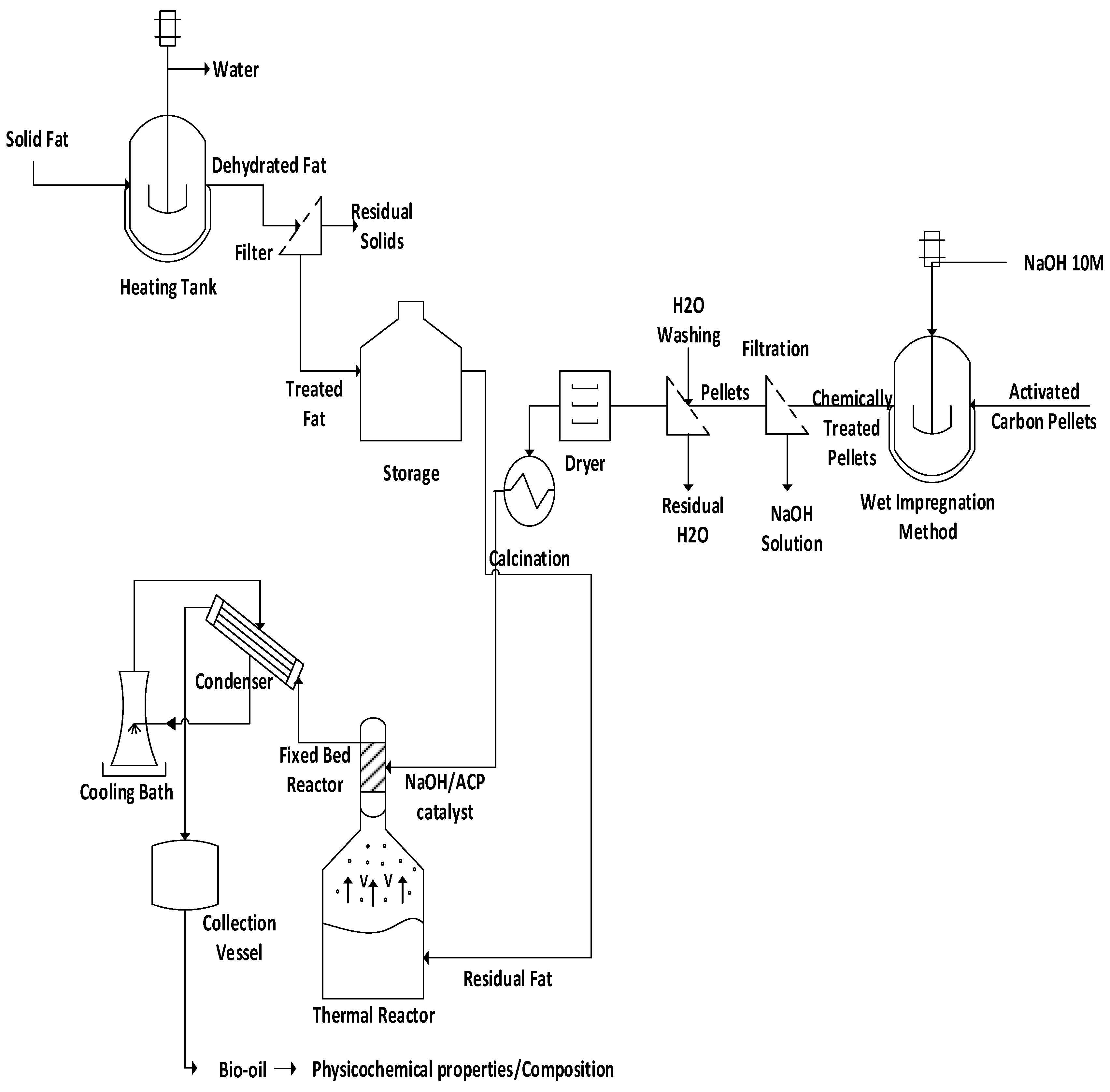
The process flowsheet illustrated in Figure 1 summarizes the applied methodology, described in a logical sequence of ideas, methods, and procedures to produce liquid mixtures rich in hydrocarbons by catalytic upgrading of residual fat pyrolysis vapors/volatiles at 400 °C and 1.0 atm, over a catalyst fixed-bed reactor, using activated carbon pellets impregnated with sodium hydroxide, in semi-pilot scale. Initially, the residual fat is collected. Afterwards, it is subjected to pre-treatment (filtration) and separation processes (evaporation, dehydration). The activated carbon pellets impregnated with NaOH. Afterwards, the impregnated carbon pellets were washed with deionized water and submitted to drying followed by thermal activation. The experiments were carried out using a two-stage process schema consisting of a pyrolysis reactor and a catalyst fixed-bed reactor. The effect of catalyst-to-residual fat and reaction time were analyzed. The physical-chemistry (density, kinematic viscosity, and acidity) properties and composition of hydrocarbons and oxygenates were determined.
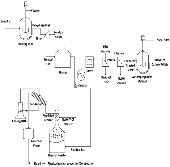
Figure 1.
Process flowsheet by catalytic upgrading of residual fat vapors at 400 °C, 1.0 atm, 0.0%, 5.0%, 7.5%, and 10.0% (wt.) of activated carbon pellets impregnated with 10.0 M NaOH, using a catalyst fixed-bed reactor, in semi-pilot scale.
2.2. Materials
The residual fat was collected from a system of grease traps at University Restaurant of UFPA, or more specifically, of one grease trap responsible for collecting fat from the cooking process of meats used in meal preparation. This trap is segregated from other traps responsible for collecting effluent of dish washing and is composed mainly of triglycerides and fatty acids. The fat was collected when the trap was full and due for cleaning. As the restaurant does not have a large menu and the grease trap collects all fat rendered over a period of one month due to frequency of cleaning the grease traps, fat composition should be relatively constant and adequate as a waste fat model.
The residual fat was submitted to pre-processing (heating, homogenization) and separation processes (dehydration, sieving), as described elsewhere [19,20,21]. By the pre-processing, the fat was subjected to heating and mechanical agitation in order to evaporate the excess moisture and homogenize the lipid-base mixture. Afterwards, the liquified fat material was sieved to remove suspended and undesired solid materials, as described synthetically in flowsheet of Figure 1. The residual fat after pre-processing is illustrated in Figure 2.
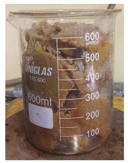
Figure 2.
Pre-treated residual fat used as feed material by catalytic upgrading of residual fat vapors at 400 °C, 1.0 atm, 0.0%, 5.0%, 7.5%, and 10.0% (wt.) activated carbon pellets impregnated with 10.0 M NaOH, using a catalyst fixed-bed reactor, in semi-pilot scale.
2.3. Chemical Activation of Commercial Activated Carbon Pellets
The pellets of activated carbon (General Carbon Co., Paterson, NJ, USA, GC C-40), chemically activated/impregnated with 10.0 M NaOH, were used as catalysts. The specifications of commercial activated carbon pellets are described in Table 1.

Table 1.
Specifications of activated carbon GC C-40.
Wet Impregnation, Drying, and Calcination
The activated carbon pellets were chemically impregnated by the wet impregnation method using a 10.0 M NaOH solution. As the wet impregnation method depends upon the diffusion of chemical precursor to internal pores of pellets, a high concentration solution of NaOH was used to obtain better diffusion rates to internal pores and effectively reach active sites on pellets. In addition, using a concentrated solution allows for a high mass ratio of NaOH to carbon pellets, ensuring that all sites could be populated by NaOH. As the wet impregnation was performed with whole pellets rather than with powdered ones, it was thought that higher concentration of NaOH would be able to produce better results as far as diffusion was concerned.
The chemical impregnation of activated carbon pellets takes place in several steps, as illustrated in Figure 1. In this sense, a more detailed description of each pre-treatment step (wet impregnation, drying, and calcination) should be highlighted for a better understanding as follows. First, 500 g of activated carbon pellets were placed in contact with 320 g of a 10.0 M NaOH solution for 4.0 h at 30 °C. Afterwards, the solution was drained using a filter. Then, the moist impregnated pellets washed with deionized water, to remove the excess NaOH, and the procedure repeated until stable pH value of 10.0 was achieved. Afterwards, the pellets were subjected to drying using an oven (Model Bio SEA—40 L) for a period of 12 h, at a temperature of 105 °C, to remove the excess water. Finally, the activated carbon pellets impregnated with NaOH were calcined at 600 °C for 03 h using a muffle (Model Bio SEA—40 L). A total of 04 batches were carried out. The commercial activated carbon before and after impregnation with sodium hydroxide is shown in Figure 3.
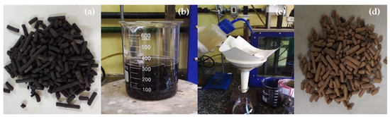
Figure 3.
Activated carbon pellets impregnated with a 10.0 M NaOH solution (activated carbon pellets (a); wet impregnation (b); water washing (c); activated carbon pellets impregnated with NaOH (d)).
2.4. Characterization of Residual Fat
Density of fat was measured with a 5 mL glass pycnometer, calibrated with distilled water, according to official method AOCS Cc 10c-95. Kinematic viscosity was determined at 40.0 °C on a temperature-controlled bath and Cannon-Fenske viscosimeter (Ø = 50) according to official method ASTM D 2515. Acid value was determined dissolving 2.0 g of fat into 125 mL of a 50/50 (%wt./wt.) toluene/isopropanol combined solvent and titrated with a standard solution of 0.1 N KOH, using phenolphthalein as acid-base indicator, according to AOCS Cd3d-63 [19,20,21,22,23].
2.5. Experimental Apparatus and Procedures
2.5.1. Experimental Apparatus
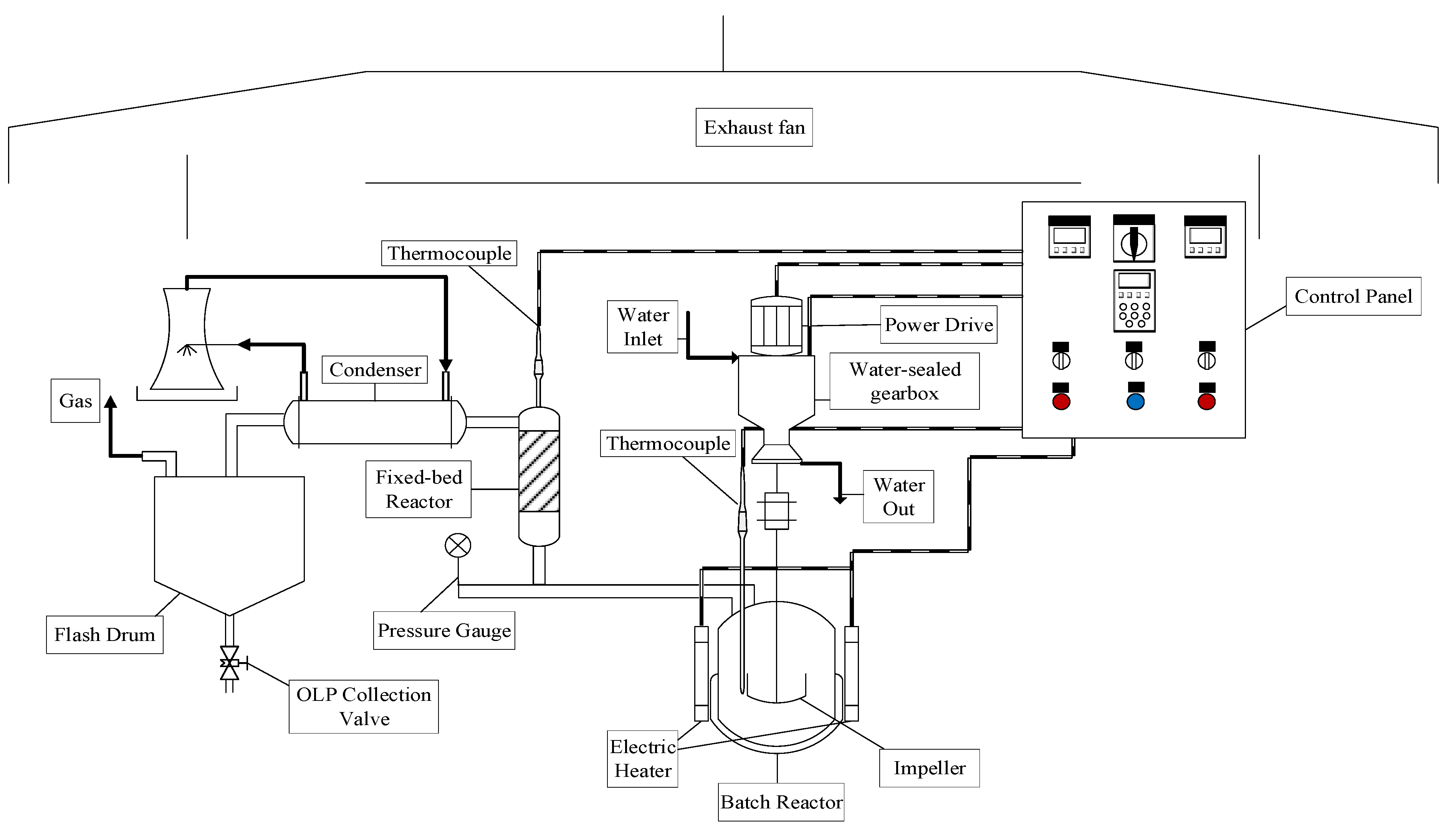
The thermal catalytic cracking unit with a fixed-bed reactor in semi-pilot scale, depicted in Figure 4, described in detail elsewhere [20]. By the thermal catalytic cracking experiments, at the output of pyrolysis/batch reactor (R-1), a second AISI 304 stainless steel fixed-bed reactor (R-2) is coupled. The fixed-bed reactor (R-2) of cylindrical geometry has 30 cm height and 15 mm internal diameter (V(R-2) = 53 mL). A spiral-shaped electrical resistance, with 1.5 kW, was inserted around the reactor (R-2). A glass wool thermal blanket was used as a thermal insulator in order to avoid energy loss to the environment. A type K sheathed thermocouple (550 °C) is placed inside the reactor (R-2) for measuring its temperature. Figure 5 shows the schematic diagram of bench scale catalytic cracking unit with a fixed bed (R-2).
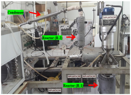
Figure 4.
Thermal catalytic cracking unit with a pyrolysis reactor (R-1) and a fixed-bed reactor (R-2) in bench scale.
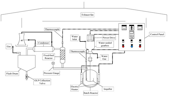
Figure 5.
Schematic diagram of bench scale stainless steel catalytic cracking reactor with a pyrolysis/batch reactor and a fixed-bed reactor.
2.5.2. Experimental Procedures
Pyrolysis
By the thermal cracking (pyrolysis) of residual fat, the residual fat was weighed (1000 g) using an electronic balance (São Paulo, Brazil, Mars, AL500). Afterwards, the residual fat is added within the stirred tank reactor (R-1), whereas pyrolysis takes place. After sealing the reactor, the experimental apparatus has been set up. Then, the cooling system is turned on and the water temperature was set at 10 °C. Afterwards, the programming step is carried out, thus making it possible to set the desired operating parameters, including heating rate (10 °C/min), cracking temperature (400 °C) and the mechanical impeller speed (100 rpm). After the experiment starts, the operational parameters (heating rate, cracking temperature, and mechanical impeller speed) were recorded every 10 min. By each thermal cracking experiment, 03-04 (three/four) samples were withdrawn along with the reaction time in order to study and/or investigate the reaction kinetics of organic liquid products. In addition, the non-condensable gases were burned at the exit of the gas pipeline line (gas flare). The mass of solid-phase products (coke) was collected and weighed, and the mass of gas was computed by difference. The liquid-phase products were submitted to pre-treatments of decantation to remove water and filtration. Then, organic liquid products were characterized for density, kinematic viscosity, refractive index, and acid value.
Thermal Catalytic Cracking
By the thermal catalytic cracking experiments, the activated carbon pellets impregnated with 10.0 M NaOH were placed inside the fixed-bed reactor (R-2). Afterwards, the reactor (R-2) was vertically coupled between the reactor (R-1) and the condenser, as shown in Figure 4. Then, the desired operating parameters are set up, including the heating rate (10 °C/min), cracking temperatures (400 °C) of both reactors (R-1) and (R-2), as well as the mechanical impeller speed (100 rpm). Furthermore, the temperature of fixed-bed reactor (R-2) was set up approximately 10 °C/20 °C higher than that of reactor (R-1), in order to avoid condensation of ascending vapors produced inside the reactor (R-1) through the porous structure of pellets catalyst and between the void volume of fixed-bed reactor (R-2). That is, thermal cracking of residual fat takes place in reactor (R-1), producing an ascending vapor phase (gas-phase reaction products) that flows through the porous structure of pellets catalyst and between the void volume of fixed-bed reactor, whereas a heterogeneous gas-solid reaction takes place in catalyst fixed bed (R-2). The thermal catalytic cracking experiments carried out with 5.0%, 7.5%, and 10.0% (wt.) chemically activated carbon pellets inside the fixed-bed reactor (R-2). By each thermal catalytic cracking experiment, 03-04 (three/four) samples were withdrawn along with the reaction time in order to study and/or investigate the reaction kinetics of organic liquid products. In addition, the non-condensable gases were burned at the exit of the gas pipeline line (gas flare). The mass of solid-phase products (coke) was collected and weighed, and the mass of gas computed by difference. The liquid-phase products were submitted to pre-treatments of decantation to remove water and filtration. Then, organic liquid products were physicochemically characterized for density, kinematic viscosity, refractive index, and acid value.
2.6. Physicochemical and Chemical Composition of Bio-Oil
2.6.1. Physicochemical Characterization of Bio-Oil and Aqueous Phase
Density of bio-oil was measured with a 5 mL glass pycnometer, calibrated with distilled water, according to official method AOCS Cc 10c-95. Kinematic viscosity was determined at 40.0 °C on a temperature-controlled bath and Cannon-Fenske viscosimeter (Ø = 50) according to official method ASTM D 2515. Acid value was determined by dissolving 0.2 g of bio-oil into 50 mL of a 50/50 (%wt./wt.) toluene/isopropanol combined solvent and titrated with a standard solution of 0.1 N KOH, using phenolphthalein as acid-base indicator, adapted from AOCS Cd3d-63 [19,20,21,22,23].
2.6.2. Chemical Composition of Bio-Oil and Aqueous Phase
The chemical composition of bio-oil and aqueous phase were determined by GC-MS and the equipment and procedure described in detail by Castro et al. [17]. The concentrations were expressed in area, as no internal standard was injected for comparison of the peak areas.
2.7. Characterization of Activated Carbon Pellets
2.7.1. SEM and EDX Analysis
The morphological characterization of activated carbon pellets impregnated with 10.0 M NaOH was performed by scanning electron microscopy using a microscope (Tescan GmbH, Czech Republic, Model: Vega 3). Magnification used were 338×, 838×, 1.67k×, 3.33k×, 5.00k×, 6.67k× with HV 15.0 KV. The samples were covered with a thin layer of gold using a Sputter Coater (Leica Biosystems, Nußloch, Germany, Model: Balzers SCD 050). Elemental analysis and mapping were carried out by energy-dispersive X-ray spectroscopy (Oxford instruments, Abingdon, UK, Model: Aztec 4.3).
2.7.2. XRD Analysis
The crystalline characterization of activated carbon pellets impregnated with 10.0 M NaOH was performed by X-ray diffraction using a diffractometer (Rigaku, Tokyo, Japan, Model: MiniFlex600) at the Laboratory of Structural Characterization (FEMAT/UNIFESSPA) and the equipment specifications described as follows: generator (maximum power: 600 W; tube voltage: 40 kV; tube current: 15 mA; X-ray tube: Cu), optics (fixed divergence, scattering and receiving slit; filter; Kβ sheet; monochromator: graphite; soller slit: 5.0°), goniometer (model: vertical; radius: 150 mm; scanning range: −3 A; 145° (2θ); scanning speed: 0.01 to 100°/min (2θ); accuracy: ±0.02°) and detector (high-speed silicone tape).
2.8. Mass Balances of Catalytic Cracking of Vapor-Phase Products
By performing a steady state global mass balance within the control volume consisting of reactors R-1 and R-2 yields Equation (1). The weight of feed, solid and bio-oil determined utilizing an analytical scale.
The process performance evaluated by computing the yields of bio-oil, solid (coke), and gas defined by Equations (2) and (3), and the yield of gas by difference, using Equation (4).
3. Results
3.1. Characterization of Catalyst
3.1.1. SEM Analysis
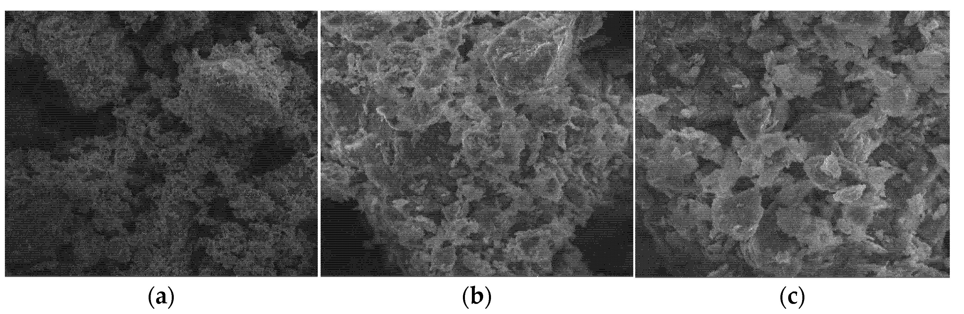
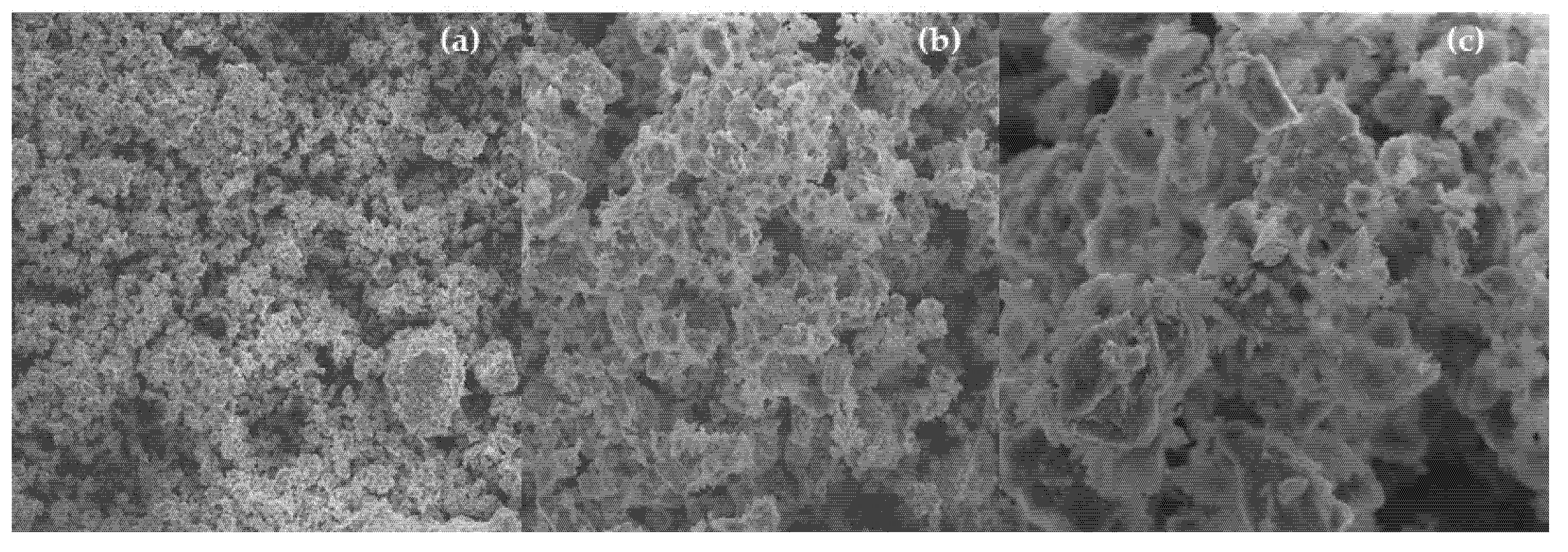
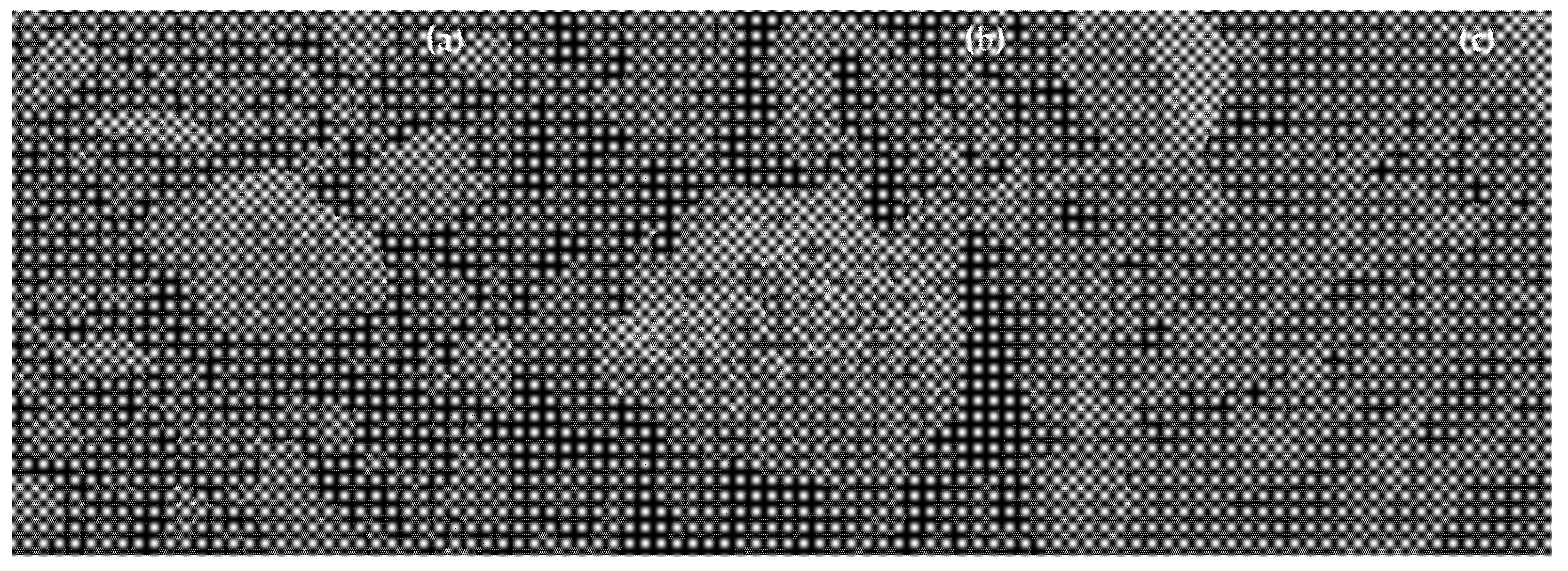
The microscopies of activated carbon pellets (General Carbon Co., GC C-40) depicted in Figure 6c show its highly porous structure, those being the SEM images according to those reported by Thakur et al. [24]. After calcination of activated carbon pellets impregnated with 10.0 M NaOH, SEM images show the appearance of cavities with sizes between 4.0 and 10.0 μm, as shown in Figure 7c, proving that high concentrated NaOH solutions has caused a great change on the activated carbon pellets morphology and texture. The SEM images of activated carbon pellets impregnated with 10.0 M NaOH after upgrading of residual fat pyrolysis vapors at 400 °C, 1.0 atmosphere, using a semi-pilot scale two-stage reactor of 2.0 L, illustrate that the porous cavities were filled with molecules of carbon due to gas–solid reactions on the surface and porous structure of activated carbon pellets, as shown in Figure 8c, corroborated in Table 2, as coke deposits may be formed on the surface of catalysts by polymerization of aromatics present in the pyrolysis vapors or formed during reaction on the gas–solid interface [25]. In fact, activated carbon pellets impregnated with 10.0 M NaOH after upgrade of residual fat pyrolysis vapors became black due to the carbonization that takes place inside the pores within the solid surface. According to Santillan-Jimenez and Crocker [26], by the catalytic deoxygenation of fatty acids into hydrocarbons via decarboxylation and/or decarbonylation, CO2 is formed by decarboxylation, while H2O and CO are formed by decarbonylation, being those compounds released into the gaseous phase.

Figure 6.
SEM of activated carbon pellets (MAG: 838× (a); MAG: 3.33 k× (b); MAG: 6.67 k× (c)).
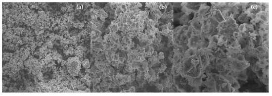
Figure 7.
SEM of activated carbon pellets impregnated with 10.0 M NaOH (MAG: 338× (a); MAG: 1.67 k× (b); MAG: 5.00 k× (c)).

Figure 8.
SEM of activated carbon pellets after catalytic upgrading of residual fat pyrolysis vapors at 400 °C, 1.0 atm, with 5.0% (wt.) activated carbon pellets impregnated with 10.0 M NaOH, in batch mode, using a semi-pilot scale reactor of 2.0 L (MAG: 838× (a); MAG: 3.33 k× (b); MAG: 6.67 k× (c)).
Table 2.
Percentages in mass and atomic mass of activated carbon pellets, activated carbon pellets impregnated with 10.0 M NaOH after calcination at 600 °C and 03 h, and activated carbon pellets impregnated with 10.0 M NaOH after upgrading of residual fat pyrolysis vapors at 400 °C, 1.0 atmosphere, using a semi-pilot scale two-stage reactor of 2.0 L.
3.1.2. EDX Analysis
Table 2 shows the results of elemental analysis performed by energy-dispersive X-ray spectroscopy at a point for activated carbon pellets, activated carbon pellets impregnated with 10.0 M NaOH after calcination at 600 °C, and activated carbon pellets impregnated with 10.0 M NaOH after upgrading of residual fat pyrolysis vapors at 400 °C, 1.0 atmosphere, using a semi-pilot scale two-stage reactor of 2.0 L. The impregnation of activated carbon pellets with sodium hydroxide had little effect on the elemental analysis, except on the elemental analysis of Silicium (Si) and Sodium (Na). The mass (wt.%) of Silicium (Si) decreases after impregnation with a 10.0 M NaOH, in accordance with to the results reported by Fertani-Gmati et al. [27], as silicates dissolve in NaOH [SiO2 + 6(NaOH)H2O(L) → (Si4O11Na6)H2O(L) + 3H2O]. In addition, the impregnation of activated carbon pellets with NaOH caused an increase on the mass (wt.%) of Sodium (Na), as shown in Table 2. After upgrading of residual fat pyrolysis vapors at 400 °C, 1.0 atmosphere, over a catalyst fixed-bed reactor packed with activated carbon chemically activated with 10.0 M NaOH, using a semi-pilot scale two-stage reactor of 2.0 L, one observes an increase on the mass (wt.%) of carbon probably due not only to the adsorption of carbon molecules within the pores of the catalyst surface, but also to formation of coke deposits on the surface of catalysts by polymerization of aromatics present in the pyrolysis vapors or formed during reaction on the gas–solid interface [25], as gas–solid reactions take place.
3.1.3. XRD Analysis
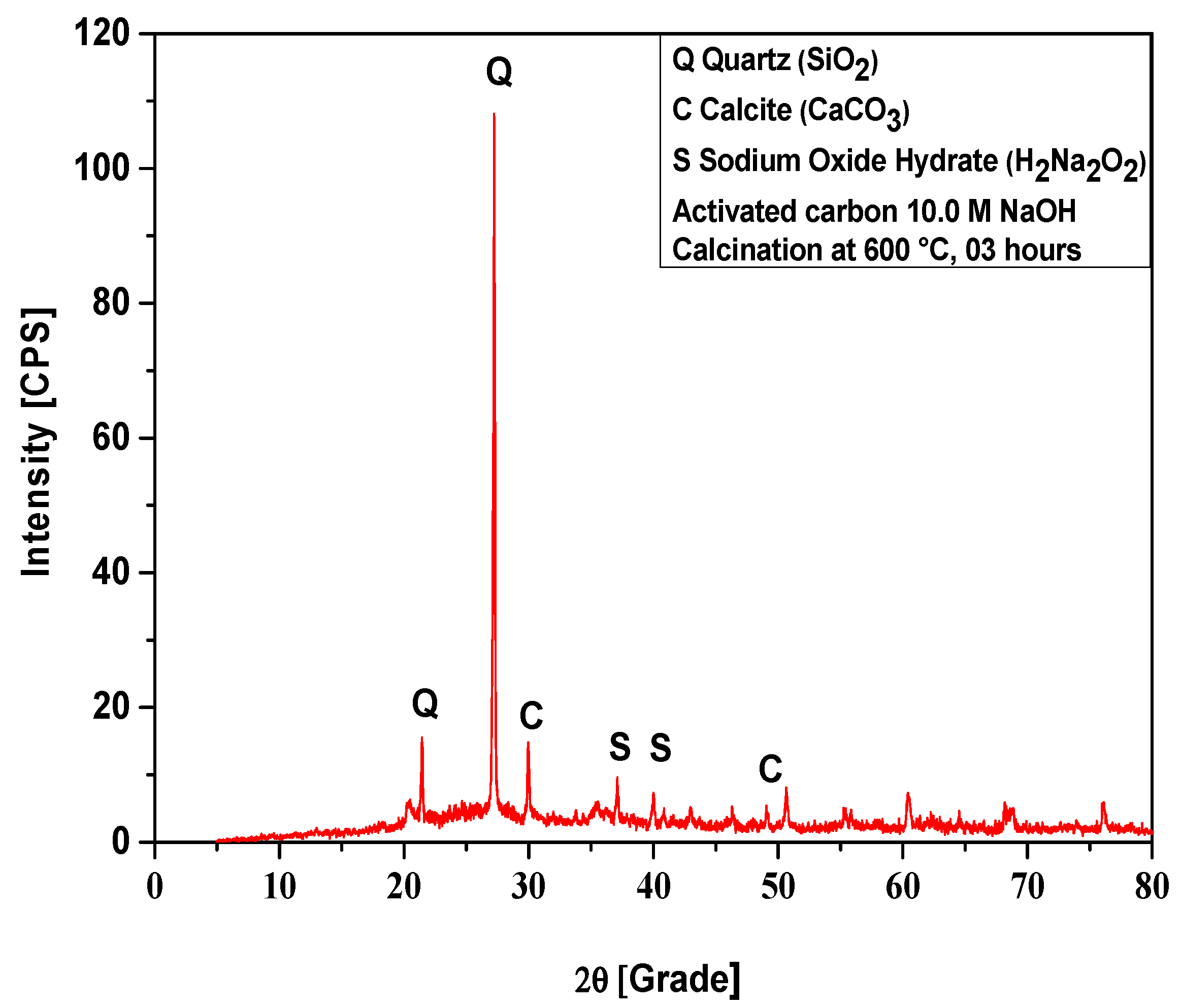
The XRD of activated carbon pellets impregnated with 10.0 M NaOH after calcination at 600 °C, 3 h, is shown in Figure 9. The diffractogram shows the presence of 3 (three) crystalline phases, Quartz (SiO2), Calcite (CaCO3), and Sodium Oxide Hydrate (H2Na2O2). For the crystalline phase Quartz, the XRD identified the presence of two peaks, one of high intensity, observed on the position 2θ: 26.6 (100%) and another of low intensity on the position 2θ: 20.8 (21.6%). The phase Calcite (CaCO3) of Rhombohedral structure was observed in two peaks, one of high intensity, observed on the position 2θ: 29.4 (100%), and another of low intensity, on the position 2θ: 48.6 (19.1%). The phase Sodium Oxide Hydrate has been observed in two peaks of intensity on the position 2θ: 37.1 and 2θ: 40.8, showing that impregnation of activated carbon pellets with NaOH was effective.

Figure 9.
XRD of activated carbon pellets impregnated with 10.0 M NaOH after calcination at 600 °C, 3 h.
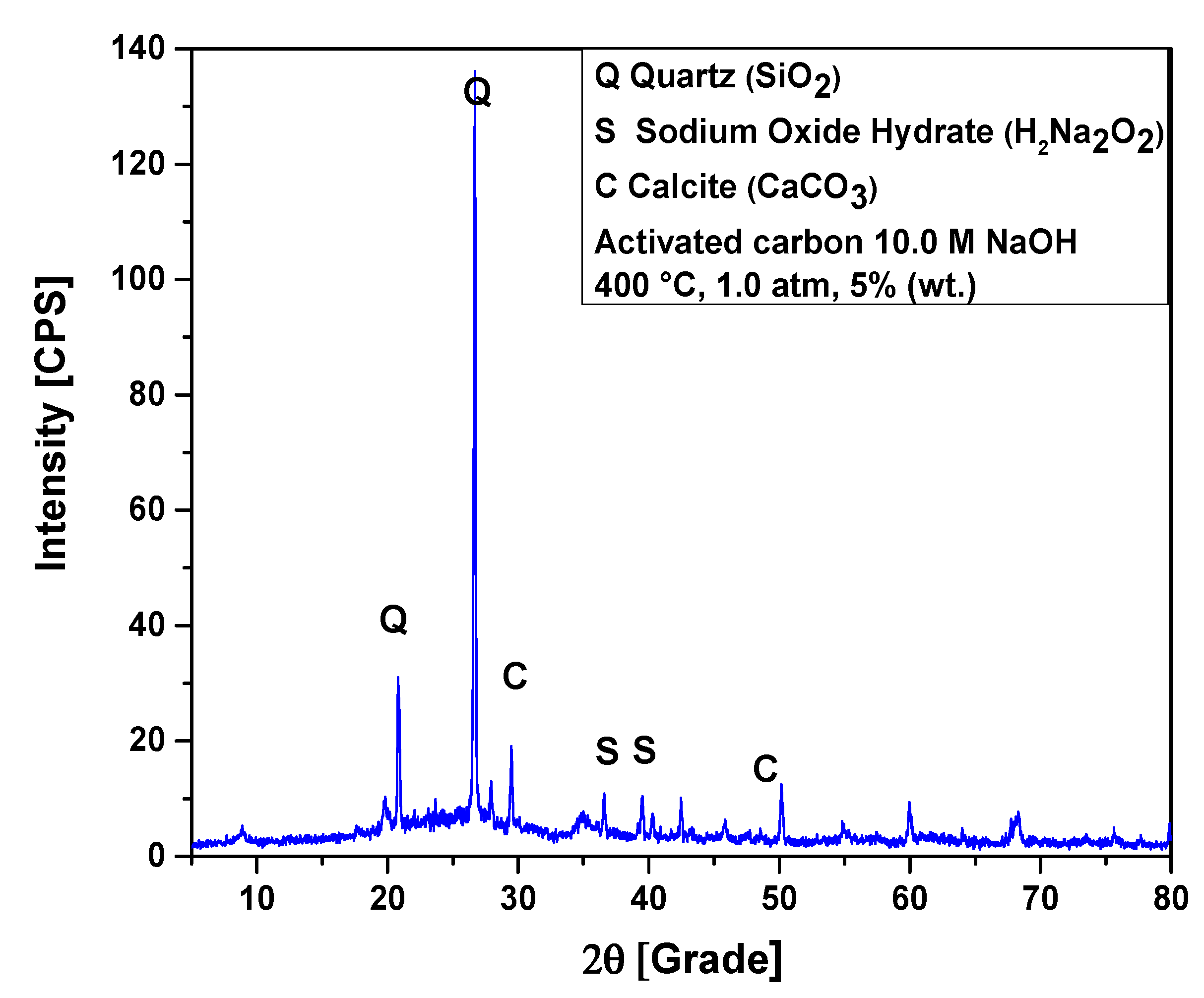
The XRD of activated carbon pellets impregnated with 10.0 M NaOH after the upgrading of residual fat pyrolysis vapors at 400 °C, 1.0 atmosphere, 5.0% (wt.) activated carbon pellets impregnated with 10.0 M NaOH, using a catalyst fixed-bed reactor, in a semi-pilot scale two-stage reactor of 2.0 L, is shown in Figure 10. The diffractogram shows the presence of three crystalline phases, Quartz (SiO2), Calcite (CaCO3), and Sodium Oxide Hydrate (H2Na2O2). The XRD identified the presence of two peaks, one of high intensity, observed on the position 2θ: 26.6 (100%) and another of low intensity on the position 2θ: 20.8 (21.6%), associated with the crystalline phase Quartz (SiO2). The peaks associated with Sodium Oxide Hydrate (H2Na2O2) were observed on the position 2θ: 37.1 and 2θ: 40.8. The phase Calcite (CaCO3) of Rhombohedral structure was observed in two peaks, one of high intensity, observed on the position 2θ: 29.4 (100%) and another of low intensity on the position 2θ: 48.6 (19.1%).
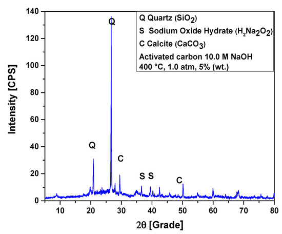
Figure 10.
XRD of activated carbon pellets impregnated with 10.0 M NaOH after the upgrading of residual fat pyrolysis vapors at 400 °C, 1.0 atmosphere, 5.0% (wt.) activated carbon pellets impregnated with 10.0 M NaOH, using a catalyst fixed-bed reactor, in a semi-pilot scale two-stage reactor of 2.0 L.
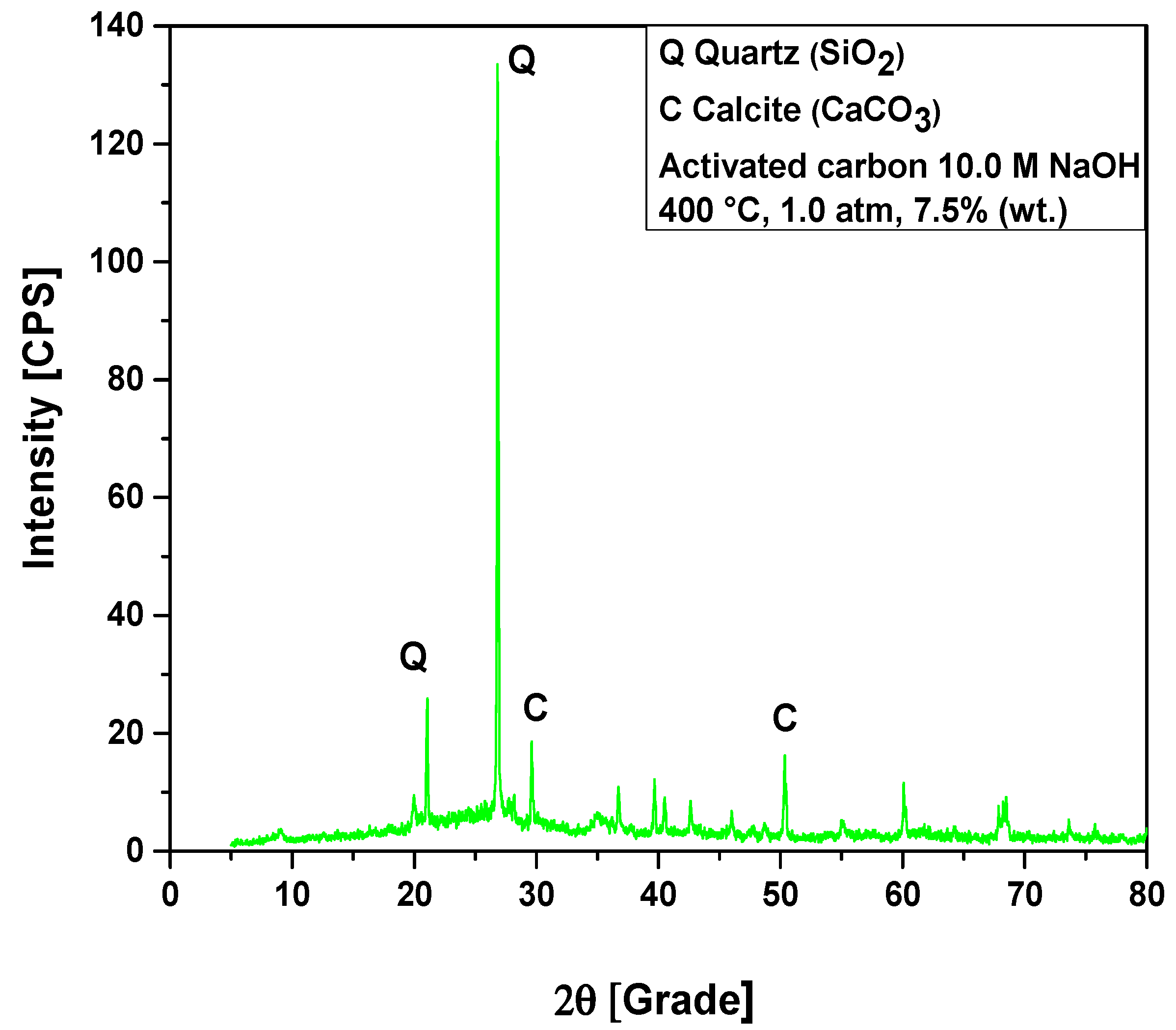
The XRD of activated carbon pellets impregnated with 10.0 M NaOH after the upgrading of residual fat pyrolysis vapors at 400 °C, 1.0 atmosphere, 7.5% (wt.) activated carbon pellets impregnated with 10.0 M NaOH, using a catalyst fixed-bed reactor, in a semi-pilot scale two-stage reactor of 2.0 L, is shown in Figure 11. The diffractogram shows the presence of two crystalline phases, Quartz (SiO2) and Calcite (CaCO3). The XRD identified the presence of two peaks, one of high intensity, observed on the position 2θ: 26.7 (100%) and another of low intensity on the position 2θ: 20.9 (21.4%), associated with the crystalline hexagonal phase Quartz (SiO2). The phase Calcite (CaCO3) of Rhombohedral structure was observed in two peaks, one of high intensity, observed on the position 2θ: 29.6 (100%) and another of low intensity on the position 2θ: 48.7 (15.0%).
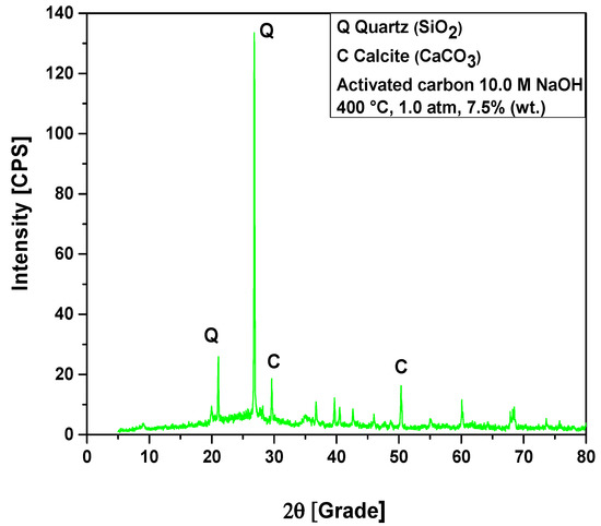
Figure 11.
XRD of activated carbon pellets impregnated with 10.0 M NaOH after the upgrading of residual fat pyrolysis vapors at 400 °C, 1.0 atmosphere, 7.5% (wt.) activated carbon pellets impregnated with 10.0 M NaOH, using a catalyst fixed-bed reactor, in a semi-pilot scale two-stage reactor of 2.0 L.
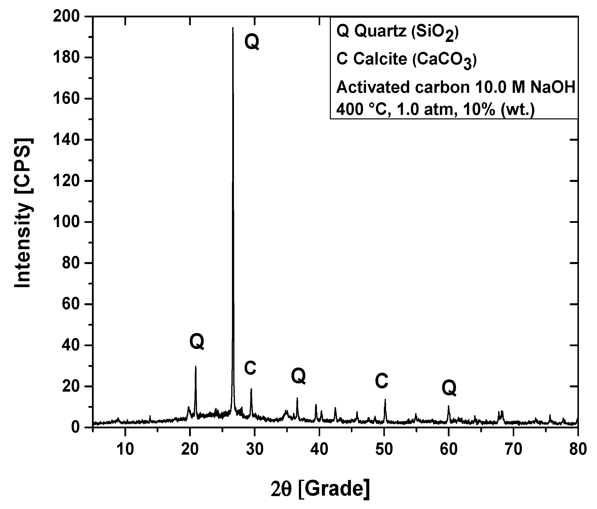
The XRD of activated carbon pellets impregnated with 10.0 M NaOH after the upgrading of residual fat pyrolysis vapors at 400 °C, 1.0 atmosphere, 10.0% (wt.) activated carbon pellets impregnated with 10.0 M NaOH, using a catalyst fixed-bed reactor, in a semi-pilot scale two-stage reactor of 2.0 L, is shown in Figure 12. The diffractogram shows the presence of two crystalline phases, Quartz (SiO2) and Calcite (CaCO3). The XRD identified the presence of two peaks, one of high intensity, observed on the position 2θ: 26.6 (100%) and another of low intensity on the position 2θ: 20.8 (21.6%), associated with the crystalline hexagonal phase Quartz (SiO2). The phase Calcite (CaCO3) of Rhombohedral structure was observed in two peaks, one of high intensity, observed on the position 2θ: 29.4 (100%) and another of low intensity on the position 2θ: 48.6 (19.1%).

Figure 12.
XRD of activated carbon pellets impregnated with 10.0 M NaOH after the upgrading of residual fat pyrolysis vapors at 400 °C, 1.0 atmosphere, 10.0% (wt.) activated carbon pellets impregnated with 10.0 M NaOH, using a catalyst fixed-bed reactor, in a semi-pilot scale two-stage reactor of 2.0 L.
3.2. Upgrading of Residual Fat Pyrolysis Vapors over Activated Carbon Pellets
3.2.1. Process Conditions, Mass Balances, and Yields of Reaction Products
Table 3 shows bio-oil yields between 30.22% and 76.41% (wt.), aqueous phase yields between 2.83% and 6.55% (wt.), solid phase yields between 4.17% and 11.18% (wt.), and gas yields between 12.87% and 55.60% (wt.). The yields of bio-oil are lower than those reported by Yu et al. [12], for the catalytic upgrade of Tallow kernel oil over SiC foam-MCM41, and by Koul et al. [13], for the catalytic upgrading of vapors from castor seed oil pyrolysis over Kaolin, CaO, and ZnO, but higher than those reported by Wang et al. [2], for catalytic upgrading of vapors from Chromolaena odorata and soybean soapstock, by Vichaphund et al. [6], for the catalytic upgrading of Jatropha waste over HZSM-5, by Wang et al. [7], for catalytic upgrading of soapstock vapors over HZSM-5, and by Wu et al. [8], for the catalytic upgrading of soapstock and straw vapors using HZSM-5 and MCM-4. The yields of bio-oil by the catalytic upgrading of lipid-base materials stays around 30.0 and 60.0% (wt.) [2,6,7,8,12,13].
Table 3.
Process parameters, mass balances, and yields of reaction products (liquids, solids, H2O, and gas) by catalytic upgrading of residual fat pyrolysis vapors at 400 °C, 1.0 atm, 0.0%, 5.0%, 7.5%, and 10.0% (wt.) activated carbon pellets impregnated with 10.0 M NaOH, using a catalyst fixed-bed reactor, in semi-pilot scale.
3.2.2. Effect of Catalyst-to-Residual Fat Ratio on the Yield of Bio-Oil
Figure 13 shows the effect of catalyst-to-biomass ration on the yields of bio-oil by the upgrading of residual fat pyrolysis vapors/volatiles at 450 °C, 1.0 atm, 0.0%, 5.0%, 7.5%, and 10.0% (wt.) activated carbon pellets impregnated with 10.0 M NaOH, using a catalyst fixed-bed reactor, in a semi-pilot scale two-stage reactor of 2.0 L, compared with similar studies in the literature [2,6,7,8,12,13].
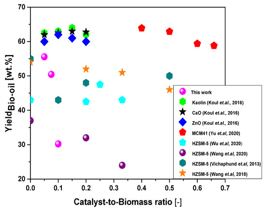
Figure 13.
Effect of catalyst-to-biomass ratio within the range 0.0–0.7 on the yield of bio-oil by the upgrading of residual fat pyrolysis vapors at 400 °C, 1.0 atmosphere, 5.0%, 7.5%, and 10.0% (wt.) activated carbon pellets impregnated with 10.0 M NaOH, using a catalyst fixed-bed reactor, in a semi-pilot scale two-stage reactor of 2.0 L, compared with similar studies in the literature [2,6,7,8,12,13].
Increasing the catalyst-to-residual fat ratio causes a decrease in the yield of bio-oil. The results are according to similar studies reported by Koul et al. [13], for the catalytic upgrading of vapors from castor seed oil pyrolysis over ZnO, between a catalyst-to-biomass ratio of 0.1 and 0.2, by Yu et al. [12], for the catalytic upgrade of Tallow kernel oil over SiC foam-MCM41, Vichaphund et al. [6], for the catalytic upgrading of Jatropha waste over HZSM-5, Wang et al. [7], for catalytic upgrading of soapstock vapors over HZSM-5, and Wang et al. [2], for catalytic upgrading of vapors from Chromolaena odorata and soybean soapstock. In all studies [2,6,7,12,13], the feed materials have a great content of lipids and most of the catalysts used were HZSM-5, except the ZnO [13]. In fact, ZnO reacts with carboxylic acids present in oils and fats, forming its corresponding carboxylates, that is, forming zinc soaps [28]. It is probably that the Sodium Oxide Hydrate (H2Na2O2), identified in the diffractogram of Figure 9, reacts with carboxylic acids present in the residual fat, forming sodium soaps. In fact, as observed by Yu et al. [12], higher catalyst-to-biomass ratios promote the formation of gas, causing an opposite effect on the yield of bio-oil [2,6,7,12,13]. According to Duan et al. [24], increasing the catalyst-to-biomass ration increases the residence time of pyrolysis vapors inside the catalyst bed, increasing the rate of catalytic cracking of vapors/volatiles, thus promoting the formation of gaseous compounds. On the contrary, the yields of gas decrease with increasing catalyst-to-biomass, which is according to the literature [12], due probably to secondary cracking of pyrolysis vapors within the catalyst bed [28,29]. Finally, it is to be expected that the type of catalyst (acid or basic), catalyst morphological and textural properties and selectivity affects the formation of liquid (bio-oil), solid (coke) and gaseous products by catalyst upgrade of pyrolysis vapors over a bed of catalyst coke [2,6,7,8,9,10,12,13]. Furthermore, the yield of reaction products and chemical composition of bio-oil are strongly dependent on process variables including reaction temperature [1,2,7,8,12], catalyst-to-biomass [1,2,3,4,6,7,8,12,13], residence time [7], and raw material composition [1,2,3,4,5,6,7,8,9,10,11,12,13].
3.2.3. Effect of Reaction Time on the Physicochemical Properties of Bio-Oil
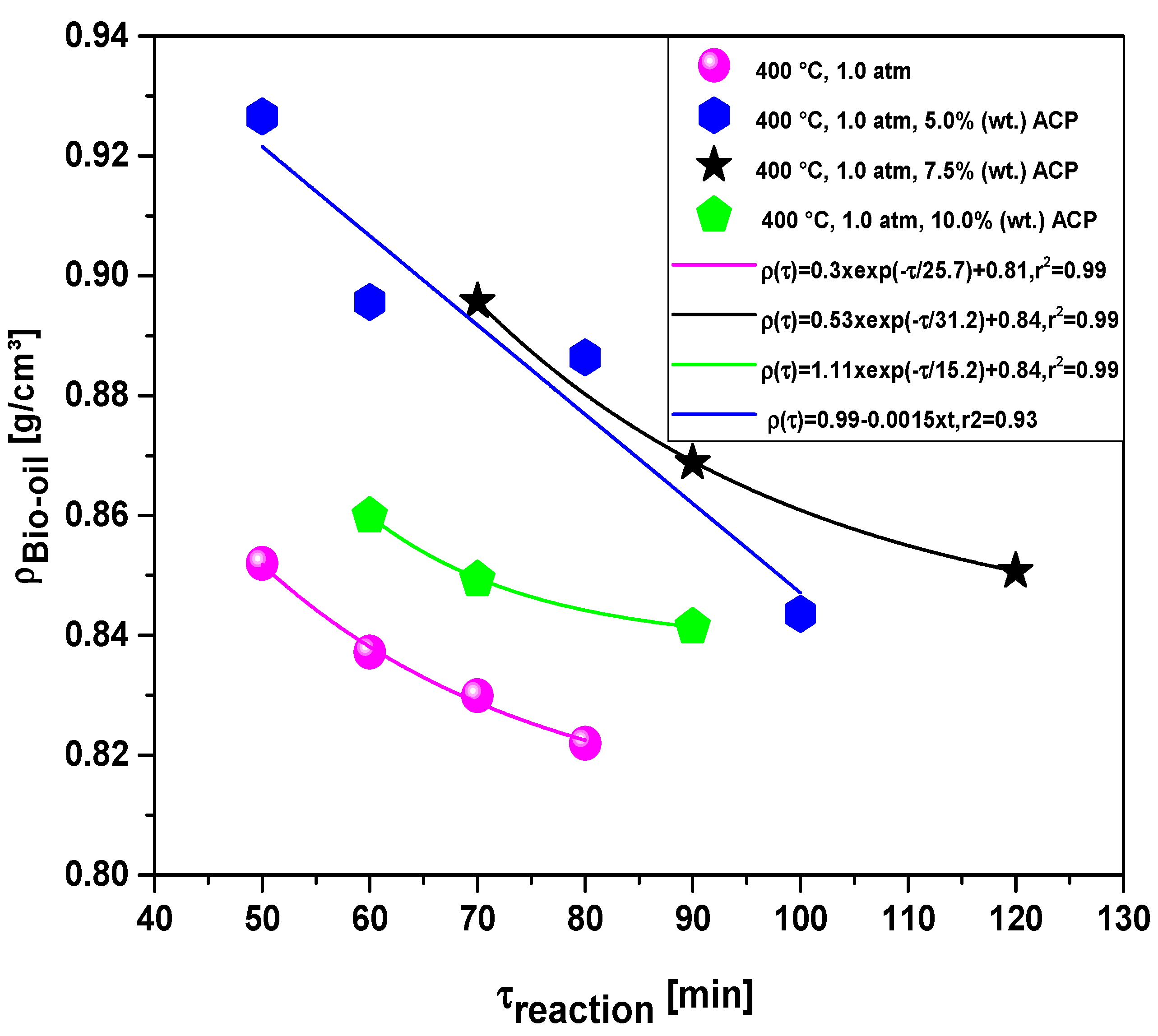
The effect of reaction time on the density, kinematic viscosity, and acidity of bio-oil by catalytic upgrading of residual fat pyrolysis vapors at 400 °C, 1.0 atm, 0.0%, 5.0%, 7.5%, and 10.0% (wt.) activated carbon pellets impregnate with 10.0 M NaOH, using a catalyst fixed-bed reactor, in a semi-pilot scale two-stage reactor of 2.0 L, is described in Table 4. The density, kinematic viscosity, and acidity of bio-oils decrease with increasing reaction time. This is because at the beginning of reaction, the primary cracking occurs, forming oxygenated compounds [14,15,16,18]. Then, in the middle to the end of the reaction, secondary cracking occurs by de-carbonylation and de-carboxylation reactions, producing hydrocarbons [14,15,16,18,30,31,32,33,34,35,36,37], and hydrocarbons have superior physicochemical properties than oxygenates, that is, lowers density, lower kinematic viscosity and lower acidity.
Table 4.
Effect of reaction time on the density, kinematic viscosity, and acidity of bio-oil by catalytic upgrading of residual fat pyrolysis vapors at 400 °C, 1.0 atm, 0.0%, 5.0%, 7.5%, and 10.0% (wt.) activated carbon pellets impregnated with 10.0 M NaOH, using a catalyst fixed-bed reactor, in a semi-pilot scale two-stage reactor of 2.0 L.
Effect of Reaction Time on the Density of Bio-Oil
The effect of reaction time on the density of bio-oil by catalytic upgrading of residual fat pyrolysis vapors at 400 °C, 1.0 atm, 0.0%, 5.0%, 7.5%, and 10.0% (wt.) of activated carbon pellets impregnated with 10.0 M NaOH, using a catalyst fixed-bed reactor, in semi-pilot scale two-stage reactor of 2.0 L, is shown in Figure 14.

Figure 14.
Effect of reaction time on the density of bio-oil by the upgrading of residual fat pyrolysis vapors at 400 °C, 1.0 atmosphere, 0.0%, 5.0%, 7.5%, and 10.0% (wt.) activated carbon pellets impregnated with 10.0 M NaOH, using a catalyst fixed-bed reactor, in a semi-pilot scale two-stage reactor of 2.0 L.
For all the experiments, the density of bio-oil decreases with reaction time. For the experiments with 0.0%, 7.5%, and 10.0% (wt.) activated carbon pellets impregnated with 10.0 M NaOH, the experimental data were correlated with a first order exponential decay model, exhibiting root-mean-square error (r2) of 0.99, while the experiment with 5.0% (wt.) activated carbon pellets impregnated with 10.0 M NaOH was correlated with a first order linear equation, exhibiting root-mean-square error (r2) of 0.93. The experiment without catalyst gives the lowers bio-oils densities, showing that a fixed bed filled with activated carbon pellets impregnated with 10.0 M NaOH promotes not only the formation of gas but also oxygenates compounds.
Effect of Reaction Time on the Viscosity of Bio-Oil
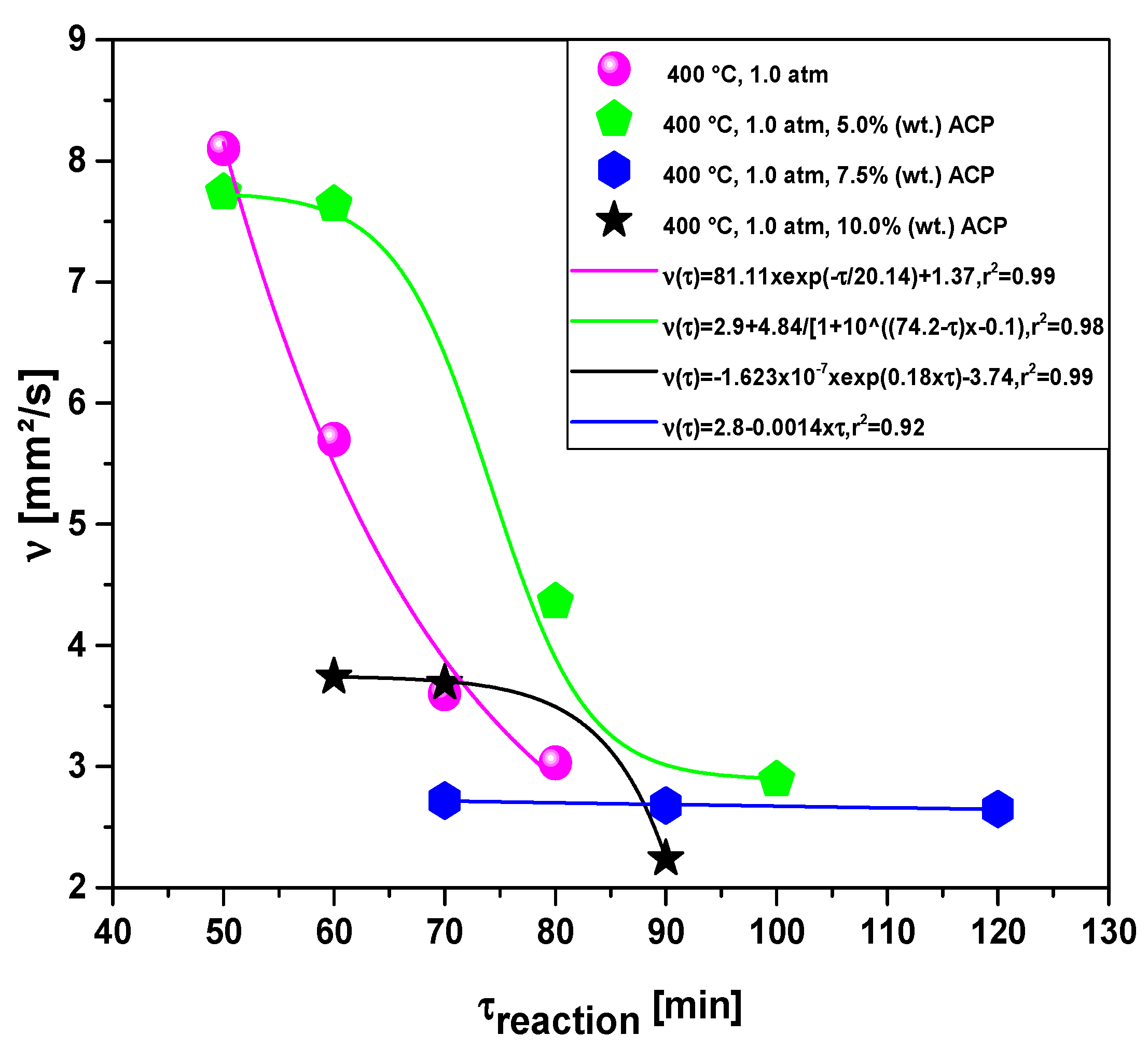
Figure 15 illustrates the effect of reaction time on the kinematic viscosity of bio-oil by catalytic upgrading of residual fat pyrolysis vapors at 400 °C, 1.0 atm, 0.0%, 5.0%, 7.5%, and 10.0% (wt.) of activated carbon pellets impregnated with 10.0 M NaOH, using a catalyst fixed-bed reactor, in semi-pilot scale two-stage reactor of 2.0 L. The kinematic viscosity of bio-oils decreases with increasing reaction time increases. The kinematic viscosity of bio-oils for the experiments without catalyst and 10.0% (wt.) activated carbon pellets impregnated with 10.0 M NaOH were correlated with a first order exponential decay and first order exponential models, respectively, exhibiting for both models, root-mean-square error (r2) of 0.99, while the experiment with 7.5% (wt.) activated carbon pellets impregnated with 10.0 M NaOH was correlated with a first order linear equation, exhibiting root-mean-square error (r2) of 0.92. For the experiment with 7.5% (wt.) activated carbon pellets impregnated with 10.0 M NaOH, the kinematic viscosity was correlated with a DoseResp (sigmoid) model, exhibiting root-mean-square error (r2) of 0.98. By DoseResp function, A1 and A2 are the bottom (initial value) and top (final value) asymptotes, respectively, where A1 is equal to 2.9 and A2 equal to 7.74. The kinematic viscosity of bio-oils decreases because at the beginning of the catalytic cracking reaction, the primary cracking occurs, forming oxygenated compounds [19,20,21,23]. Then, in the middle to the end of the reaction, secondary cracking occurs by de-carbonylation and de-carboxylation, producing hydrocarbons [19,20,21,23,30,31,32,33,34,35,36,37], and hydrocarbons have much lower viscosity than oxygenates.

Figure 15.
Effect of reaction time on the kinematic viscosity of bio-oil by the upgrading of residual fat pyrolysis vapors at 400 °C, 1.0 atmosphere, 0.0%, 5.0%, 7.5%, and 10.0% (wt.) of activated carbon pellets impregnated with 10.0 M NaOH, using a catalyst fixed-bed reactor, in a semi-pilot scale two-stage reactor of 2.0 L.
Effect of Reaction Time on the Acidity of Bio-Oil
The influence of reaction time on the density of bio-oil by catalytic upgrading of residual fat pyrolysis vapors at 450 °C, 1.0 atm, 0.0%, 5.0%, 7.5%, and 10.0% (wt.) of Red Mud pellets activated with 1.0 M HCl, using a catalyst fixed-bed reactor, in semi-pilot scale two-stage reactor of 2.0 L, is shown in Figure 16. The acidity of bio-oil, expressed by the acid value, decreases drastically with increasing reaction time. The experiments without catalyst, with 7.5% and 10.0% (wt.) activated carbon pellets impregnated with 10.0 M NaOH were correlated with a first order exponential decay model, exhibiting root-mean-square error (r2) between 0.98 and 0.99, while the experiments with 5.0% (wt.) activated carbon pellets impregnated with 10.0 M NaOH were correlated with a first order exponential model, exhibiting root-mean-square errors (r2) of 0.99. This is due to the catalytic deoxygenation of triglycerides and fatty acids molecules, the main compounds of vegetable oils and animal fats, into hydrocarbons through de-carboxylation/de-carbonylation as reported in the literature [38,39].
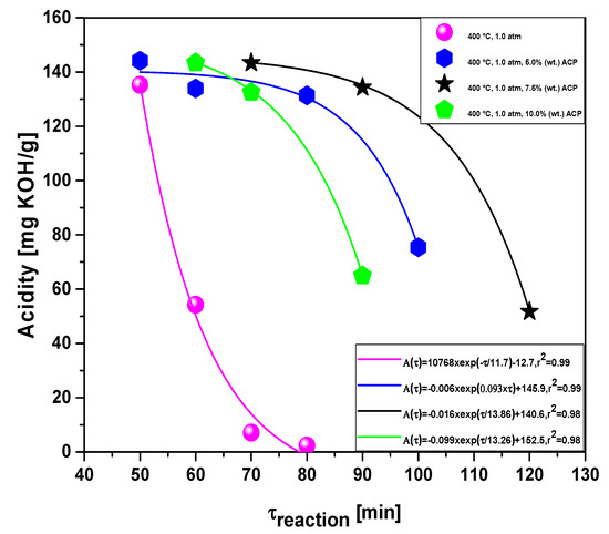
Figure 16.
Effect of reaction time on the acidity of bio-oil by the upgrading of residual fat pyrolysis vapors at 400 °C, 1.0 atmosphere, 0.0%, 5.0%, 7.5%, and 10.0% (wt.) of activated carbon pellets impregnated with 10.0 M NaOH, using a catalyst fixed-bed reactor, using a semi-pilot scale two-stage reactor of 2.0 L.
As observed in Figure 16, as soon as the first sample is withdrawn, the acid value is very high, ranging between 135.26 and 144.14 mg KOH/g, due to formation of carboxylic acids, associated with the primary cracking. Afterwards, in the middle to the end of the reaction, deoxygenation of triglycerides and fatty acids molecules occurs by means of de-carboxylation/de-carbonylation, producing mixtures rich in hydrocarbons and poor in oxygenates, particularly carboxylic acids [38,39].
3.2.4. Effect of Reaction Time on the Selectivity of Hydrocarbons and Oxygenates in Bio-Oil
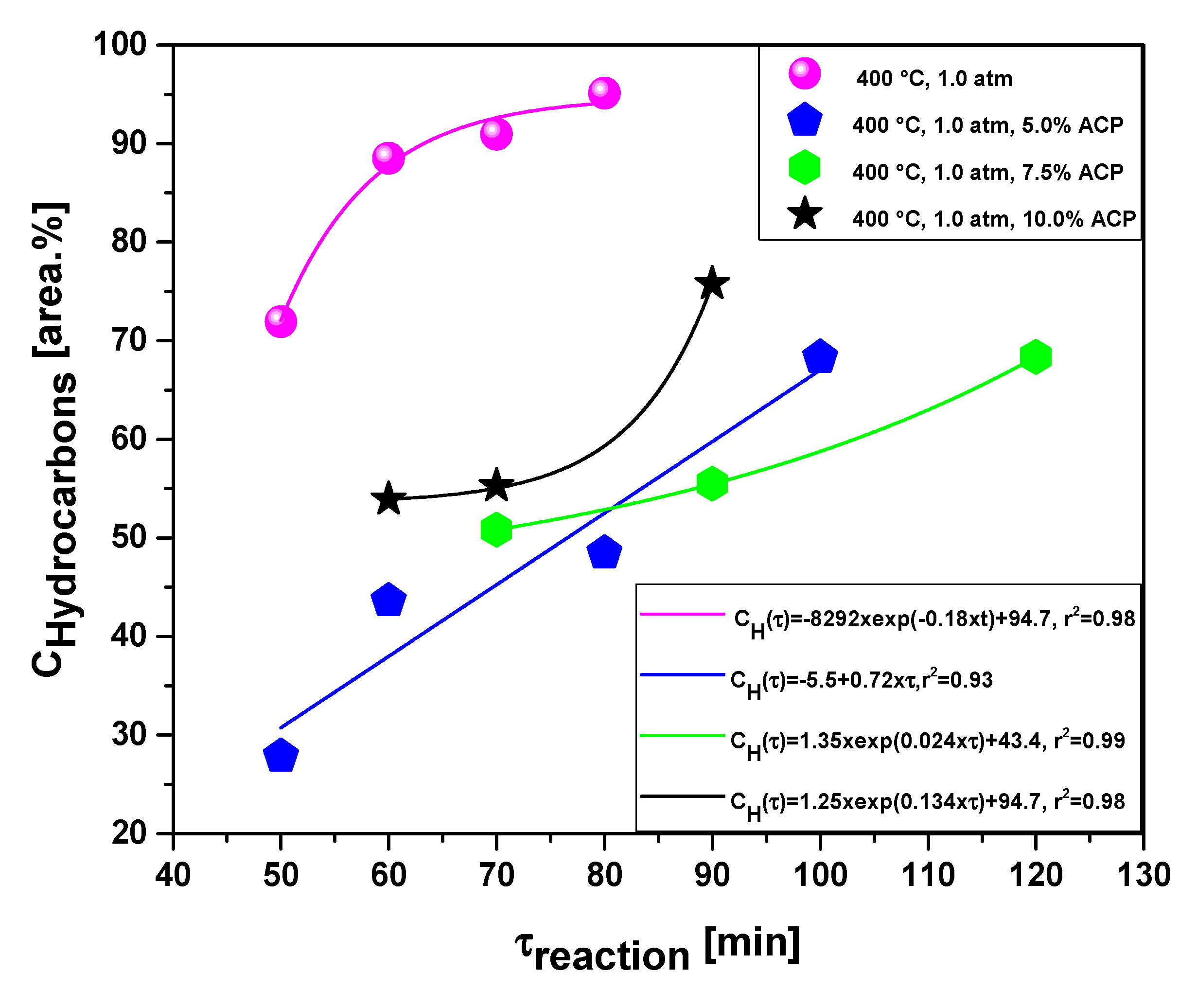
Table 5 and Figure 17 and Figure 18 illustrate the effect of reaction time on the selectivity of hydrocarbons and oxygenates in bio-oils, respectively, by the upgrading of residual fat pyrolysis vapors at 400 °C, 1.0 atmosphere, 0.0%, 5.0%, 7.5%, and 10.0% (wt.) activated carbon pellets impregnated with 10.0 M NaOH, using a catalyst fixed-bed reactor, using a semi-pilot scale two-stage reactor of 2.0 L.
Table 5.
Effect of reaction time on the concentration of bio-oil by catalytic upgrading of residual fat pyrolysis vapors at 450 °C, 1.0 atm, 0.0, 5.0, 7.5, and 10.0% (wt.) activated carbon pellets impregnated with 10.0 M NaOH, using a catalyst fixed-bed reactor, in a semi-pilot scale two-stage reactor of 2.0 L.
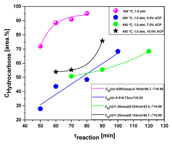
Figure 17.
Effect of reaction time on the selectivity of hydrocarbons by the upgrading of residual fat pyrolysis vapors at 400 °C, 1.0 atmosphere, 0.0%, 5.0%, 7.5%, and 10.0% (wt.) activated carbon pellets impregnated with 10.0 M NaOH, using a catalyst fixed-bed reactor, in a semi-pilot scale two-stage reactor of 2.0 L.

Figure 18.
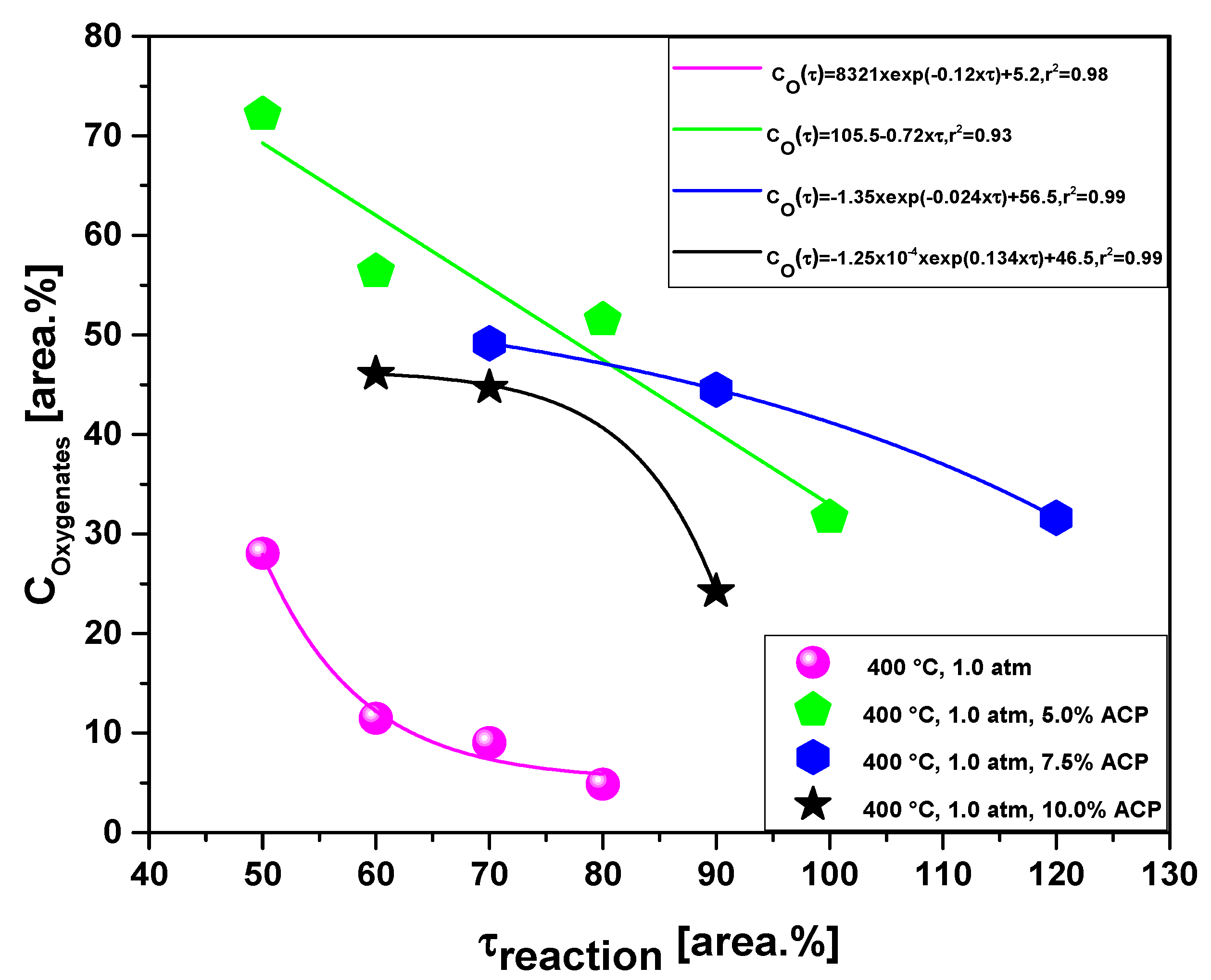
Effect of reaction time on the selectivity of oxygenates by the upgrading of residual fat pyrolysis vapors at 450 °C, 1.0 atmosphere, 0.0%, 5.0%, 7.5%, and 10.0% (wt.) activated carbon pellets impregnated with 10.0 M NaOH, using a catalyst fixed-bed reactor, using a semi-pilot scale two-stage reactor of 2.0 L.
The chemical functions (alkanes, alkenes, alkynes, ring-containing alkanes, ring-containing alkenes, aromatics, carboxylic acids, aldehydes, alcohols, and ketones), sum of peak areas, CAS numbers, and retention times of all the molecules identified in bio-oil by GC-MS by the upgrading of residual fat pyrolysis vapors at 400 °C, 1.0 atmosphere, 0.0, 5.0, 7.5, and 10.0% (wt.) activated carbon pellets impregnated with 10.0 M NaOH, during the course of reaction at 50, 60, 70, 80, 90, 100 and 120 min, using a catalyst fixed-bed reactor, in a semi-pilot scale two-stage reactor of 2.0 L, are illustrated in Supplementary Tables S1–S14.
The concentration of hydrocarbons in bio-oil increases with reaction time. The experiments without catalyst, 7.5 and 10.0% (wt.) activated carbon pellets impregnated with 10.0 M NaOH were correlated with a first order exponential model, exhibiting for all regressions, root-mean-square errors (r2) of 0.98, while the experiment with 5.0% (wt.) activated carbon pellets impregnated with 10.0 M NaOH was correlated with a first order linear equation, exhibiting root-mean-square error (r2) of 0.93. The concentration of hydrocarbons in bio-oil increases due to the catalytic deoxygenation of fatty acids molecules, by means of de-carboxylation/de-carbonylation, producing aliphatic and aromatic hydrocarbons, as reported in the literature [38,39]. The results are according to similar studies reported in the literature [1,3,4,6,8]. On the contrary, the concentration of oxygenates in bio-oil decreases with increasing reaction time. The experiments without catalyst, 7.5 and 10.0% (wt.) activated carbon pellets impregnated with 10.0 M NaOH were correlated with a first order exponential model, exhibiting for all regressions, root-mean-square errors (r2) between 0.98 and 0.99, while the experiments with 5.0% (wt.) activated carbon pellets impregnated with 10.0 M NaOH was correlated with a first order linear equation, exhibiting root-mean-square error (r2) of 0.93.
4. Conclusions
The thermal catalytic cracking of residual fat show bio-oils yields from 55.55 to 30.22 (wt.%), aqueous phase yields between 2.83 and 3.19 (wt.%), solid phase yields between 13.56 and 9.75 (wt.%), and gas yields from 27.89 to 55.60 (wt.%). The yields of bio-oil decreases from 74.41% to 30.22% (wt.) with increasing catalyst-to-Tallow kernel oil ratio, while that of gaseous phase increases from 12.87% to 55.60% (wt.). For all the thermal and thermal catalytic cracking experiments, the density, kinematic viscosity, and acid value of bio-oils decreases as the reaction time increases varying from 0.9266 to 0.8220 g/cm3, 8.10 to 2.24 mm2/s, and 144.14 to 2.37 mg KOH/g. The GC-MS of liquid reaction products identified the presence of hydrocarbons (alkanes, alkenes, ring-containing alkanes, ring-containing alkenes, and aromatics) and oxygenates (carboxylic acids, ketones, esters, alcohols, and aldehydes). For all the pyrolysis and catalytic cracking experiments, the hydrocarbon selectivity in bio-oil increases with increasing reaction time, while that of oxygenates decreases, reaching concentrations of hydrocarbons up to 95.35% (area). The best results for the physicochemical properties density, kinematic viscosity, and acid value were 0.8220 g/cm3, 3.03 mm2/s, and 2.37 mg KOH/g, respectively, with a maximum hydrocarbon concentration of 97.194% (area) and 2.806% ketones (area) were obtained at 400 °C and 1.0 atmosphere, 80 min, without catalyst. For the catalytic cracking experiments, the maximum hydrocarbon content of 75.763% (area) and 17.041% (area) carboxylic acids, 4.702% (area) ketones (area), and 2.494% (area) non-identified oxygenates was obtained at 400 °C and 1.0 atmosphere, 90 min, using a catalyst fixed-bed reactor, with 10.0% (wt.) activated carbon pellets impregnated with 10.0 M NaOH as catalyst.
The activated carbon pellets impregnated with 10.0 M NaOH were not selective to promote the deoxygenation of triglycerides and fatty acids molecules by means of de-carboxylation/de-carbonylation, as the acidity of bio-oils was high compared to the experiments without catalyst. On the other hand, as the de-carboxylation and de-carbonylation has not taken place, there was little formation of CO and CO2, and it is to be expected that the gaseous products were rich in hydrocarbons of short chain length.
Supplementary Materials
The following supporting information can be downloaded at: https://www.mdpi.com/article/10.3390/en15134587/s1. Table S1: Classes of compounds, summation of peak areas, CAS number, and retention times of chemical compounds identified by CG-MS in bio-oil by pyrolysis of residual fat at 400 °C, 1.0 atm, 50 min, using a pyrolysis reactor of 2.0 L, in semi-pilot scale. Table S2: Classes of compounds, summation of peak areas, CAS number, and retention times of chemical compounds identified by CG-MS in bio-oil by pyrolysis of residual fat at 400 °C, 1.0 atm, 60 min, using a pyrolysis reactor of 2.0 L, in semi-pilot scale. Table S3: Classes of compounds, summation of peak areas, CAS number, and retention times of chemical compounds identified by CG-MS in bio-oil by pyrolysis of residual fat at 400 °C, 1.0 atm, 70 min, using a pyrolysis reactor of 2.0 L, in semi-pilot scale. Table S4: Classes of compounds, summation of peak areas, CAS number, and retention times of chemical compounds identified by CG-MS in bio-oil by pyrolysis of residual fat at 400 °C, 1.0 atm, 80 min, using a pyrolysis reactor of 2.0 L, in semi-pilot scale. Table S5: Classes of compounds, summation of peak areas, CAS number, and retention times of chemical compounds identified by CG-MS in bio-oil by catalytic upgrading of residual fat pyrolysis vapors at 400 °C, 1.0 atm, 5.0% (wt.) activated carbon pellets impregnated with 10.0 M NaOH, 50 min, using a catalyst fixed-bed reactor, in semi-pilot scale two-stage reactor of 2.0 L. Table S6: Classes of compounds, summation of peak areas, CAS number, and retention times of chemical compounds identified by CG-MS in bio-oil by catalytic upgrading of residual fat pyrolysis vapors at 400 °C, 1.0 atm, 5.0% (wt.) activated carbon pellets impregnated with 10.0 M NaOH, 60 min, using a catalyst fixed-bed reactor, in semi-pilot scale two-stage reactor of 2.0 L. Table S7: Classes of compounds, summation of peak areas, CAS number, and retention times of chemical compounds identified by CG-MS in bio-oil by catalytic upgrading of residual fat pyrolysis vapors at 400 °C, 1.0 atm, 5.0% (wt.) activated carbon pellets impregnated with 10.0 M NaOH, 80 min, using a catalyst fixed-bed reactor, in semi-pilot scale two-stage reactor of 2.0 L. Table S8: Classes of compounds, summation of peak areas, CAS number, and retention times of chemical compounds identified by GC-MS in bio-oil by catalytic upgrading of residual fat pyrolysis vapors at 400 °C, 1.0 atm, 5.0% (wt.) activated carbon pellets impregnated with 10.0 M NaOH, 100 min, using a catalyst fixed-bed reactor, in semi-pilot scale two-stage reactor of 2.0 L. Table S9: Classes of compounds, summation of peak areas, CAS number, and retention times of chemical compounds identified by GC-MS in bio-oil by catalytic upgrading of residual fat pyrolysis vapors at 400 °C, 1.0 atm, 7.5% (wt.) activated carbon pellets impregnated with 10.0 M NaOH, 70 min, using a catalyst fixed-bed reactor, in semi-pilot scale two-stage reactor of 2.0 L. Table S10: Classes of compounds, summation of peak areas, CAS number, and retention times of chemical compounds identified by GC-MS in bio-oil by catalytic upgrading of residual fat pyrolysis vapors at 400 °C, 1.0 atm, 7.5% (wt.) activated carbon pellets impregnated with 10.0 M NaOH, 90 min, using a catalyst fixed-bed reactor, in semi-pilot scale two-stage reactor of 2.0 L. Table S11: Classes of compounds, summation of peak areas, CAS number, and retention times of chemical compounds identified by GC-MS in bio-oil by catalytic upgrading of residual fat pyrolysis vapors at 400 °C, 1.0 atm, 7.5% (wt.) activated carbon pellets impregnated with 10.0 M NaOH, 120 min, using a catalyst fixed-bed reactor, in semi-pilot scale two-stage reactor of 2.0 L. Table S12: Classes of compounds, summation of peak areas, CAS number, and retention times of chemical compounds identified by GC-MS in bio-oil by catalytic upgrading of residual fat pyrolysis vapors at 400 °C, 1.0 atm, 10.0% (wt.) activated carbon pellets impregnated with 10.0 M NaOH, 60 min, using a catalyst fixed-bed reactor, in semi-pilot scale two-stage reactor of 2.0 L. Table S13: Classes of compounds, summation of peak areas, CAS number, and retention times of chemical compounds identified by GC-MS in bio-oil by catalytic upgrading of residual fat pyrolysis vapors at 400 °C, 1.0 atm, 10.0% (wt.) activated carbon pellets impregnated with 10.0 M NaOH, 70 min, using a catalyst fixed-bed reactor, in semi-pilot scale two-stage reactor of 2.0 L. Table S14: Classes of compounds, summation of peak areas, CAS number, and retention times of chemical compounds identified by GC-MS in bio-oil by catalytic upgrading of residual fat pyrolysis vapors at 400 °C, 1.0 atm, 10.0% (wt.) activated carbon pellets impregnated with 10.0 M NaOH, 90 min, using a catalyst fixed-bed reactor, in semi-pilot scale two-stage reactor of 2.0 L.
Author Contributions
The individual contributions of all the co-authors are provided as follows: L.P.B. contributed with formal analysis and writing original draft preparation, investigation and methodology; C.C.F. contributed with investigation and methodology; A.F.d.F.C. contributed with investigation and methodology; H.J.d.S.R. contributed with investigation and methodology; W.G.d.S. contributed with chemical analysis; L.M.P. contributed with chemical analysis; A.M.P. contributed with chemical analysis; N.L.M. contributed with chemical analysis; F.P.d.C.A. contributed with chemical analysis; S.A.P.d.M. contributed with chemical analysis and formal analysis; D.A.R.d.C. contributed with investigation, methodology and chemical analysis; M.C.S. contributed with formal analysis, investigation and methodology; N.M.M. contributed with contributed with resources, chemical analysis; S.D.J. contributed with resources, chemical analysis; L.E.P.B. with co-supervision, and resources; N.T.M. contributed with supervision, conceptualization, and data curation. All authors have read and agreed to the published version of the manuscript.
Funding
This research received no external funding.
Institutional Review Board Statement
Not applicable.
Informed Consent Statement
Not applicable.
Acknowledgments
I would like to acknowledge and dedicate this research in memory to Hélio da Silva Almeida, who used to work at the Faculty of Sanitary and Environmental Engineering/UFPa, and passed away on 13 March 2021. His contagious joy, dedication, intelligence, honesty, seriousness, and kindness will always be remembered in our hearts.
Conflicts of Interest
The authors declare no conflict of interest.
References
- Zainan, N.H.; Srivatsa, S.C.; Fanghua, L.; Bhattacharya, S. Quality of bio-oil from catalytic pyrolysis of microalgae Chlorella vulgaris. Fuel 2018, 223, 12–19. [Google Scholar] [CrossRef]
- Wang, Y.; Wu, Q.; Duan, D.; Ruan, R.; Liu, Y.; Dai, L.; Zhou, Y.; Zhao, Y.; Zhang, S.; Zeng, Z.; et al. Ex-Situ Catalytic Upgrading of Vapors from Fast Microwave-Assisted Co-Pyrolysis of Chromolaena Odorata and Soybean Soapstock. Bioresour. Technol. 2018, 261, 306–312. [Google Scholar] [CrossRef]
- Kaewpengkrow, P.; Atong, D.; Sricharoenchaikul, V. Selective Catalytic Fast Pyrolysis of Jatropha Curcas Residue with Metal Oxide Impregnated Activated Carbon for Upgrading Bio-Oil. Int. J. Hydrogen Energy 2017, 42, 18397–18409. [Google Scholar] [CrossRef]
- Kaewpengkrow, P.; Atong, D.; Sricharoenchaikul, V. Catalytic Upgrading of Pyrolysis Vapors from Jatropha Wastes Using Alumina, Zirconia and Titania Based Catalysts. Bioresour. Technol. 2014, 163, 262–269. [Google Scholar] [CrossRef] [PubMed] [Green Version]
- Yi, L.; Liu, H.; Li, M.; Man, G.; Yao, H. Prevention of CaO Deactivation Using Organic Calcium Precursor during Multicyclic Catalytic Upgrading of Bio-Oil. Fuel 2020, 271, 117692. [Google Scholar] [CrossRef]
- Vichaphund, S.; Aht-ong, D.; Sricharoenchaikul, V.; Atong, D. Catalytic Upgrading Pyrolysis Vapors of Jatropha Waste Using Metal Promoted ZSM-5 Catalysts: An Analytical PY-GC/MS. Renew. Energy 2014, 65, 70–77. [Google Scholar] [CrossRef] [Green Version]
- Wang, Y.; Wu, Q.; Yang, S.; Yang, Q.; Wu, J.; Ma, Z.; Jiang, L.; Yu, Z.; Dai, L.; Liu, Y.; et al. Microwave-Assisted Catalytic Fast Pyrolysis Coupled with Microwave-Absorbent of Soapstock for Bio-Oil in a Downdraft Reactor. Energy Convers. Manag. 2019, 185, 11–20. [Google Scholar] [CrossRef]
- Wu, Q.; Wang, Y.; Jiang, L.; Yang, Q.; Ke, L.; Peng, Y.; Yang, S.; Dai, L.; Liu, Y.; Ruan, R. Microwave-Assisted Catalytic Upgrading of Co-Pyrolysis Vapor Using HZSM-5 and MCM-41 for Bio-Oil Production: Co-Feeding of Soapstock and Straw in a Downdraft Reactor. Bioresour. Technol. 2020, 299, 122611. [Google Scholar] [CrossRef]
- Wu, Q.; Wang, Y.; Peng, Y.; Ke, L.; Yang, Q.; Jiang, L.; Dai, L.; Liu, Y.; Ruan, R.; Xia, D.; et al. Microwave-Assisted Pyrolysis of Waste Cooking Oil for Hydrocarbon Bio-Oil over Metal Oxides and HZSM-5 Catalysts. Energy Convers. Manag. 2020, 220, 113124. [Google Scholar] [CrossRef]
- Ma, W.; Liu, B.; Zhang, R.; Gu, T.; Ji, X.; Zhong, L.; Chen, G.; Ma, L.; Cheng, Z.; Li, X. Co-Upgrading of Raw Bio-Oil with Kitchen Waste Oil through Fluid Catalytic Cracking (FCC). Appl. Energy 2018, 217, 233–240. [Google Scholar] [CrossRef]
- Melo, J.A.; de Sá, M.S.; Moral, A.; Bimbela, F.; Gandía, L.M.; Wisniewski, A. Renewable Hydrocarbon Production from Waste Cottonseed Oil Pyrolysis and Catalytic Upgrading of Vapors with Mo-Co and Mo-Ni Catalysts Supported on γ-Al2O3. Nanomaterials 2021, 11, 1659. [Google Scholar] [CrossRef] [PubMed]
- Yu, Z.; Jiang, L.; Wang, Y.; Li, Y.; Ke, L.; Yang, Q.; Peng, Y.; Xu, J.; Dai, L.; Wu, Q.; et al. Catalytic Pyrolysis of Woody Oil over SiC Foam-MCM41 Catalyst for Aromatic-Rich Bio-Oil Production in a Dual Microwave System. J. Clean. Prod. 2020, 255, 120179. [Google Scholar] [CrossRef]
- Koul, M.; Shadangi, K.P.; Mohanty, K. Effect of Catalytic Vapour Cracking on Fuel Properties and Composition of Castor Seed Pyrolytic Oil. J. Anal. Appl. Pyrolysis 2016, 120, 103–109. [Google Scholar] [CrossRef]
- Morgan, T.; Grubb, D.; Santillan-Jimenez, E.; Crocker, M. Conversion of Triglycerides to Hydrocarbons Over Supported Metal Catalysts. Top. Catal. 2010, 53, 820–829. [Google Scholar] [CrossRef]
- Tani, H.; Hasegawa, T.; Shimouchi, M.; Asami, K.; Fujimoto, K. Selective Catalytic Decarboxy-Cracking of Triglyceride to Middle-Distillate Hydrocarbon. Catal. Today 2011, 164, 410–414. [Google Scholar] [CrossRef]
- Wu, J.; Shi, J.; Fu, J.; Leidl, J.A.; Hou, Z.; Lu, X. Catalytic Decarboxylation of Fatty Acids to Aviation Fuels over Nickel Supported on Activated Carbon. Sci. Rep. 2016, 6, 27820. [Google Scholar] [CrossRef] [PubMed] [Green Version]
- Asikin-Mijan, N.; Ooi, J.M.; AbdulKareem-Alsultan, G.; Lee, H.V.; Mastuli, M.S.; Mansir, N.; Alharthi, F.A.; Alghamdi, A.A.; Taufiq-Yap, Y.H. Free-H2 Deoxygenation of Jatropha Curcas Oil into Cleaner Diesel-Grade Biofuel over Coconut Residue-Derived Activated Carbon Catalyst. J. Clean. Prod. 2020, 249, 119381. [Google Scholar] [CrossRef]
- Altalhi, A.A.; Mohammed, E.A.; Morsy, S.S.M.; Negm, N.A.; Farag, A.A. Catalyzed Production of Different Grade Biofuels Using Metal Ions Modified Activated Carbon of Cellulosic Wastes. Fuel 2021, 295, 120646. [Google Scholar] [CrossRef]
- Da Silva Almeida, H.; Corrêa, O.A.; Eid, J.G.; Ribeiro, H.J.; de Castro, D.A.R.; Pereira, M.S.; Pereira, L.M.; de Andrade Mâncio, A.; Santos, M.C.; da Silva Souza, J.A.; et al. Production of Biofuels by Thermal Catalytic Cracking of Scum from Grease Traps in Pilot Scale. J. Anal. Appl. Pyrolysis 2016, 118, 20–33. [Google Scholar] [CrossRef]
- Da Silva Almeida, H.; Corrêa, O.A.; Eid, J.G.; Ribeiro, H.J.; de Castro, D.A.R.; Pereira, M.S.; Pereira, L.M.; de Andrade Aâncio, A.; Santos, M.C.; da Mota, S.A.; et al. Performance of Thermochemical Conversion of Fat, Oils, and Grease into Kerosene-like Hydrocarbons in Different Production Scales. J. Anal. Appl. Pyrolysis 2016, 120, 126–143. [Google Scholar] [CrossRef]
- Da Silva Almeida, H.; Corrêa, O.A.; Ferreira, C.C.; Ribeiro, H.J.; de Castro, D.A.R.; Pereira, M.S.; de Andrade Mâncio, A.; Santos, M.C.; da Mota, S.A.P.; da Silva Souza, J.A.; et al. Diesel-like Hydrocarbon Fuels by Catalytic Cracking of Fat, Oils, and Grease (FOG) from Grease Traps. J. Energy Inst. 2017, 90, 337–354. [Google Scholar] [CrossRef]
- Rocha de Castro, D.; da Silva Ribeiro, H.; Hamoy Guerreiro, L.; Pinto Bernar, L.; Jonatan Bremer, S.; Costa Santo, M.; da Silva Almeida, H.; Duvoisin, S.; Pizarro Borges, L.; Teixeira Machado, N. Production of Fuel-Like Fractions by Fractional Distillation of Bio-Oil from Açaí (Euterpe Oleracea Mart.) Seeds Pyrolysis. Energies 2021, 14, 3713. [Google Scholar] [CrossRef]
- Da Mota, S.A.P.; Mancio, A.A.; Lhamas, D.E.L.; de Abreu, D.H.; da Silva, M.S.; dos Santos, W.G.; de Castro, D.A.R.; de Oliveira, R.M.; Araújo, M.E.; Borges, L.E.P.; et al. Production of Green Diesel by Thermal Catalytic Cracking of Crude Palm Oil (Elaeis Guineensis Jacq) in a Pilot Plant. J. Anal. Appl. Pyrolysis 2014, 110, 1–11. [Google Scholar] [CrossRef]
- Thakur, A.K.; Sathyamurthy, R.; Velraj, R.; Lynch, I.; Saidur, R.; Pandey, A.K.; Sharshir, S.W.; Ma, Z.; GaneshKumar, P.; Kabeel, A.E. Sea-Water Desalination Using a Desalting Unit Integrated with a Parabolic Trough Collector and Activated Carbon Pellets as Energy Storage Medium. Desalination 2021, 516, 115217. [Google Scholar] [CrossRef]
- Appleby, W.G.; Gibson, J.W.; Good, G.M. Coke Formation in Catalytic Cracking. Ind. Eng. Chem. Process. Des. Dev. 1962, 1, 102–110. [Google Scholar] [CrossRef]
- Santillan-Jimenez, E.; Crocker, M. Catalytic Deoxygenation of Fatty Acids and Their Derivatives to Hydrocarbon Fuels via Decarboxylation/Decarbonylation. J. Chem. Technol. Biotechnol. 2012, 87, 1041–1050. [Google Scholar] [CrossRef]
- Fertani-Gmati, M.; Brahim, K.; Khattech, I.; Jemal, M. Thermochemistry and Kinetics of Silica Dissolution in NaOH Solutions: Effect of the Alkali Concentration. Thermochim. Acta 2014, 594, 58–67. [Google Scholar] [CrossRef]
- Beerse, M.; Keune, K.; Iedema, P.; Woutersen, S.; Hermans, J. Evolution of Zinc Carboxylate Species in Oil Paint Ionomers. ACS Appl. Polym. Mater. 2020, 2, 5674–5685. [Google Scholar] [CrossRef]
- Duan, D.; Wang, Y.; Dai, L.; Ruan, R.; Zhao, Y.; Fan, L.; Tayier, M.; Liu, Y. Ex-Situ Catalytic Co-Pyrolysis of Lignin and Polypropylene to Upgrade Bio-Oil Quality by Microwave Heating. Bioresour. Technol. 2017, 241, 207–213. [Google Scholar] [CrossRef]
- Serrão, A.C.M.; Silva, C.M.S.; da Costa Assunção, F.P.; da Silva Ribeiro, H.J.; Santos, M.C.; da Silva Almeida, H.; Junior, S.D.; Borges, L.E.P.; de Castro, D.A.R.; Machado, N.T. Análise do processo de pirólise de sementes de açaí (euterpe oleracea, mart): Influência da temperatura no rendimento dos produtos de reação e nas propriedades físico-químicas do bio-óleo / process analysis of pyrolise of açaí (euterpe oleracea, mart) see. Braz. J. Dev. 2021, 7, 18200–18220. [Google Scholar] [CrossRef]
- Mota, S.A.P.; Mancio, A.A.; Santanna, J.S.; de Jesus Pantoja Gama, V.; Machado, N.T. Influence of the Reaction Time on the Quality (Physical-Chemical Properties) of Biofuels Obtained through Catalytic Cracking of Crude Palm Oil. Sci. Plena 2021, 17, 6. [Google Scholar] [CrossRef]
- Valois, F.P.; Cardoso, A.R.B.; da Costa França Neto, R.; Pereira, L.M.; Lhamas, D.E.L.; da Mota, S.A.P.; da Silva Almeida, H.; Borges, L.E.P.; Machado, N.T.; Santos, M.C. Craqueamento Termo-Catalítico Da Borra de Neutralização Do Óleo de Palma Utilizando-Se CaCO3 Como Catalisador / Thermal Catalytic Cracking of Soap Phase Residue of Neutralization Process of Palm Oil Using CaCO3 as Catalyst. Braz. J. Dev. 2021, 7, 59461–59481. [Google Scholar] [CrossRef]
- Oliveira, R.M.; Rodrigues, E.C.; Cardoso, D.N.P.; Santos, W.G.; Machado, N.T. Thermocatalytic Cracking of Fat from Fat Boxes with Activated Red Mud. Braz. J. Dev. 2020, 6, 19876–19887. [Google Scholar] [CrossRef]
- Pereira, L.M.; Machado, N.T.; da Silva Almeida, H.; da Costa Assunção, F.P.; dos Santos Rosa Junior, L. Caracterização de Biocarvão via Craqueamento Térmico Catalítico a Partir Do Blend Do Lodo de Esgoto e Gordura Residual Em Escala Piloto. Braz. J. Dev. 2020, 6, 1502–1509. [Google Scholar] [CrossRef]
- Mancio, A.A.; da Mota, S.A.P.; Ferreira, C.C.; Carvalho, T.U.S.; Neto, O.S.; Zamian, J.R.; Araújo, M.E.; Borges, L.E.P.; Machado, N.T. Separation and Characterization of Biofuels in the Jet Fuel and Diesel Fuel Ranges by Fractional Distillation of Organic Liquid Products. Fuel 2018, 215, 212–225. [Google Scholar] [CrossRef]
- Mâncio, A.A.; da Costa, K.M.B.; Ferreira, C.C.; Santos, M.C.; Lhamas, D.E.L.; da Mota, S.A.P.; Leão, R.A.; de Souza, R.O.M.A.; Araújo, M.E.; Borges, L.E.P.; et al. Process Analysis of Physicochemical Properties and Chemical Composition of Organic Liquid Products Obtained by Thermochemical Conversion of Palm Oil. J. Anal. Appl. Pyrolysis 2017, 123, 284–295. [Google Scholar] [CrossRef]
- Santos, M.C.; Lourenço, R.M.; de Abreu, D.H.; Pereira, A.M.; de Castro, D.A.R.; Pereira, M.S.; Almeida, H.S.; Mâncio, A.A.; Lhamas, D.E.L.; da Mota, S.A.P.; et al. Gasoline-like Hydrocarbons by Catalytic Cracking of Soap Phase Residue of Neutralization Process of Palm Oil (Elaeis Guineensis Jacq). J. Taiwan Inst. Chem. Eng. 2017, 71, 106–119. [Google Scholar] [CrossRef]
- Santillan-Jimenez, E.; Morgan, T.; Lacny, J.; Mohapatra, S.; Crocker, M. Catalytic Deoxygenation of Triglycerides and Fatty Acids to Hydrocarbons over Carbon-Supported Nickel. Fuel 2013, 103, 1010–1017. [Google Scholar] [CrossRef]
- Chen, H.; Wu, Y.; Qi, S.; Chen, Y.; Yang, M. Deoxygenation of Octanoic Acid Catalyzed by Hollow Spherical Ni/ZrO2. Appl. Catal. A Gen. 2017, 529, 79–90. [Google Scholar] [CrossRef]


Publisher’s Note: MDPI stays neutral with regard to jurisdictional claims in published maps and institutional affiliations. |
© 2022 by the authors. Licensee MDPI, Basel, Switzerland. This article is an open access article distributed under the terms and conditions of the Creative Commons Attribution (CC BY) license (https://creativecommons.org/licenses/by/4.0/).