Article

Comparative Simulation Analysis of Selected Medium and High Voltage Surge Protection Devices

by
Michał Borecki
1,* and
Yevhen Kharchenko
2
1
Institute of Theory of Electrical Engineering, Warsaw University of Technology, Koszykowa 75, 00-662 Warszawa, Poland
2
Lviv University of Technology, Nadbystrzycka 38D, 20-618 Lublin, Poland
*
Author to whom correspondence should be addressed.
Energies 2022, 15(12), 4326; https://doi.org/10.3390/en15124326
Submission received: 4 May 2022 / Revised: 25 May 2022 / Accepted: 8 June 2022 / Published: 13 June 2022

Abstract

:
The aim of the article is to present and analyze the processes occurring as a result of installing a long flashover arrester (LFA) and a multi-chamber arrester (MCA) as overvoltage protection of power networks. The numerical models of LFA and MCA will be made in order to carry out simulations in the scope of selected structural elements of the considered overvoltage protection device. The above research is a significant supplement to the information on the selection of an effective solution for overvoltage protection.

1. Introduction and Principle of Operation of Selected Surge Protection Devices

Power grids are an important element that ensures reliable operation production. To ensure the reliability of the power grid, various overvoltage protection measures are used [1].
In the absence of overvoltage protection measures installed on overhead lines, each lightning strike in such a line may fail [2,3]. Due to changing climatic conditions, selected power grids fail depending on their location, as a result of lightning strikes in more than half of the cases [4].
To reduce or eliminate emergency cases as a result of lightning strikes in the network power, various overvoltage protection devices are used [5,6]. At the same time, new solutions are implemented in the field of overvoltage protection [7].
The criterion for the use of a certain type of surge protection device is primarily value. The value of the device depends on the materials from which the device is made, their characteristics, service life, inspection frequency, etc. [8].
In addition to the existing solutions, there are also new surge protection devices, such as MCA or LFA [9,10,11,12,13], among others.
Researching the field of new devices and various conditions for carrying out these tests requires the standardization or clarification of the already known results [14]. For the sake of the generality of the available data and the characteristics of the device, the discussed analysis will be a valuable supplement in the context of specifying the details of the functioning of the new overvoltage protection devices [15,16,17].
Listed in [18,19,20], the devices used to protect overhead lines against the effects of lightning discharges, could now be safely considered as the most widespread and developmental. However, none of them is characterized by absolute perfection, which, after all, is not available, but on the basis of the analysis of their features, one can identify those that attract attention due to their effectiveness, competitiveness, and modifiability. There are several types of new devices that are used in power networks. First, their short description is presented, and then a comparison of the possibilities of their application is presented.
The most important effect of a long flashover arrester (Figure 1) is taking over the discharge from the insulator surface to its own surface. This situation occurs due to the fact that the voltage-time characteristics of the LFA are below the voltage-time characteristics of the protected isolator. Due to the much lower dielectric strength than the strength of the insulator, the discharge develops avalanche.
In addition, a modification of the above solution was created in order to connect a given type of device from two sides to the cable. LFA, on the other hand, is one of the most widespread solutions that is based on the development of sliding discharges.
There are several types of devices whose operating principle is similar [20].
Of course, there are various ways to analyze the effectiveness of overvoltage protection [21,22,23,24]; the article focuses on the simulation analysis of selected devices.
The inner diameter of the of the arrester type isolated tube should be larger than the diameter of the conduit to allow the tube to move along the phase conductor. As a result of the reinforcement of the wire insulation on the section where the pipe is installed, the reliability of the line is increased. In the event of an overvoltage, at the beginning there is a jump on the insulator, and then the discharge slides over the surface of the insulated tube, which is attached to the insulator; then, along the channel, the current flows to the ground. Due to the very long length of the discharge channel, the jump does not transform into an arc and the line continues to operate without shutdowns.
In the case of the arrester insulator, the main goal is to provide a very long way to develop a discharge along the spiral electrode, which is installed on the insulator bowls. Electrodes are installed in the top and bottom of this system. In the case of applying a sufficiently large surge voltage to the insulator, a spark in the spark gap occurs and the discharge of the discharge to the electrode. In the spark, the current flows from the upper part of the electrode through the channel along the electrode in the form of a spiral to the bottom part of the electrode. The presence of an electrode that has the same potential with the insulator base leads to an increase in the electric field at the end of the discharge channel. Thanks to this, we obtain better conditions for sliding development along the surface of the insulator, and not a shorter route, through the air. Due to the very long length of the spiral electrode, which favors the creation of a long discharge channel, the discharge does not transform into an arc and the line continues to operate without shutdowns.
The modified version of this type of arrester is the multi-chamber arrester. The detailed operation of this device has been described in [25].
The module type of LFA consists of three modules. These modules are connected to a metal line clamp and terminal grounded by internal spark gaps. Thanks to this, a different speed of discharge development is ensured. First, there is a jump of the extreme modules and then the middle module. The result is a long discharge channel that creates one long hop channel.
The arrester is highly effective in protecting the line against direct lightning strikes. For this purpose, it must be installed on all phases on each pole of the protected section of the overhead line. Providing a low resistance to grounding is a common feature of all devices of this type. A low resistance should be achieved on several poles when approaching an overhead line to a power substation. The remaining poles do not have to be specially grounded. In the case of protection against direct lightning strikes, only selected parts of the line should be followed by a different rule. On all poles, we must install modular spark gaps for each phase of the protected fragment, whereas the extreme poles of this fragment must be earthed, ensuring minimum resistance values below 10 Ohms. In the case when such values cannot be achieved, one should strive to minimize the resistance of the earthing of the column to several extreme pillars of the protected part of the line.
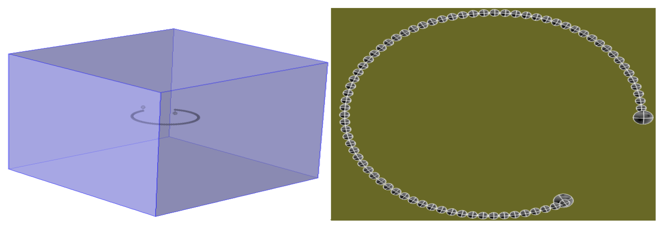
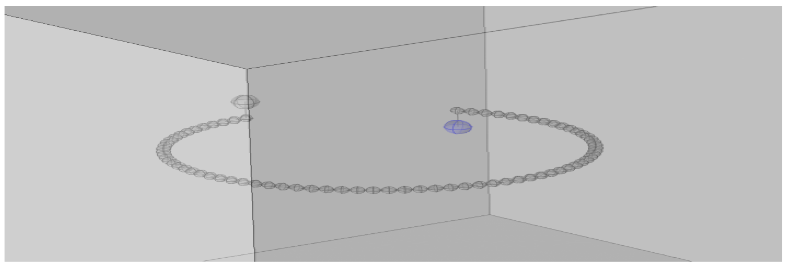
The principle of operation of the above-mentioned arrester was taken into account in the following types of overvoltage protection devices for higher voltages, such as MCA (Figure 2 and Figure 3) and the MCA arrester insulator.
The properties of the installed overvoltage protection device and the method and place of its installation require a very thorough analysis, because it depends on the parameters of the overhead line, the types of poles on which it is installed, and the resistance of the ground. In the case of very high values of the earthing resistance of the pole, it is necessary to install a spark gap for all phases. In the case of grounding resistance, which is at the level of 10 to 100 Ohm, the spark gaps are installed on the upper and lower phase, whereas for the pole resistance below 10 Ohm, the installation location depends on additional parameters, such as the presence of a lightning conductor on the line. For minimum values of pole ground resistance, when the line is equipped with a lightning conductor, there is no need to install sparks, but for resistance, which is between 5 and 10 Ohm, the lower phase of the line must be equipped with a spark gap. In the case of a line that is not equipped with a lightning conductor, the situation is different: for the minimum resistances, only the upper phase of the line should be equipped, and for the higher resistances, the upper and lower phase should be equipped.
This type of arrester is a basic device that is used to protect 110 kV and 220 kV networks. The operating principle of this device is also used in medium voltage networks. That is why this type was chosen for detailed analysis and comparison with LFA.

2. Materials and Methods

A numerical model of two types of spark gaps (LFA and MCA) consists of the most important elements that have been developed (Figure 1), which helps to compare the obtained results in the laboratory with simulations made in the COMSOL Multiphysics environment. These models will be useful during further work on the possible improvement of the surge protection method.
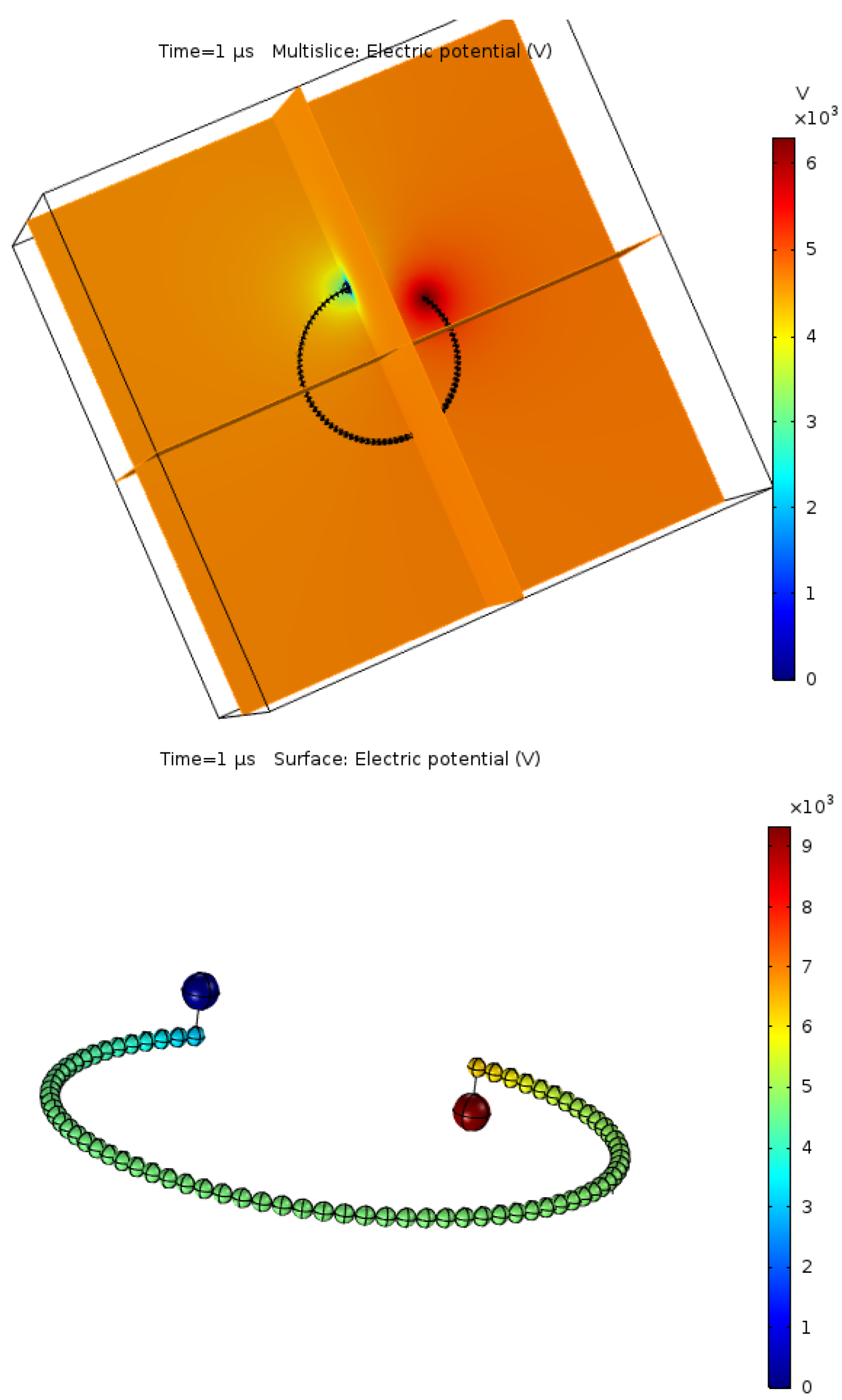
The above-mentioned models include the most important structural elements that ensure the proper functioning of the device. For these models (Figure 4), a standard lightning impulse voltage of 1.2/50 µs (normalized) was applied, whose shape was based on the following Equation (1).
u ( t ) = A 0 ( e a t e b t ) ,
where A 0 is the reference amplitude, which is 1.037264 j U ; a and b are the constant damping of the normalized lightning impulse function, which amount to 14,659 s 1 and 2,468,000 s 1 , respectively.
As a result of applying a voltage shock to the considered MCA model, as it is shown in (Figure 4 and Figure 5), we will analyze the electric field intensity level. Simulations were carried out in dynamic mode, and the results are presented for selected time segments from the time the potential was applied.

3. Results

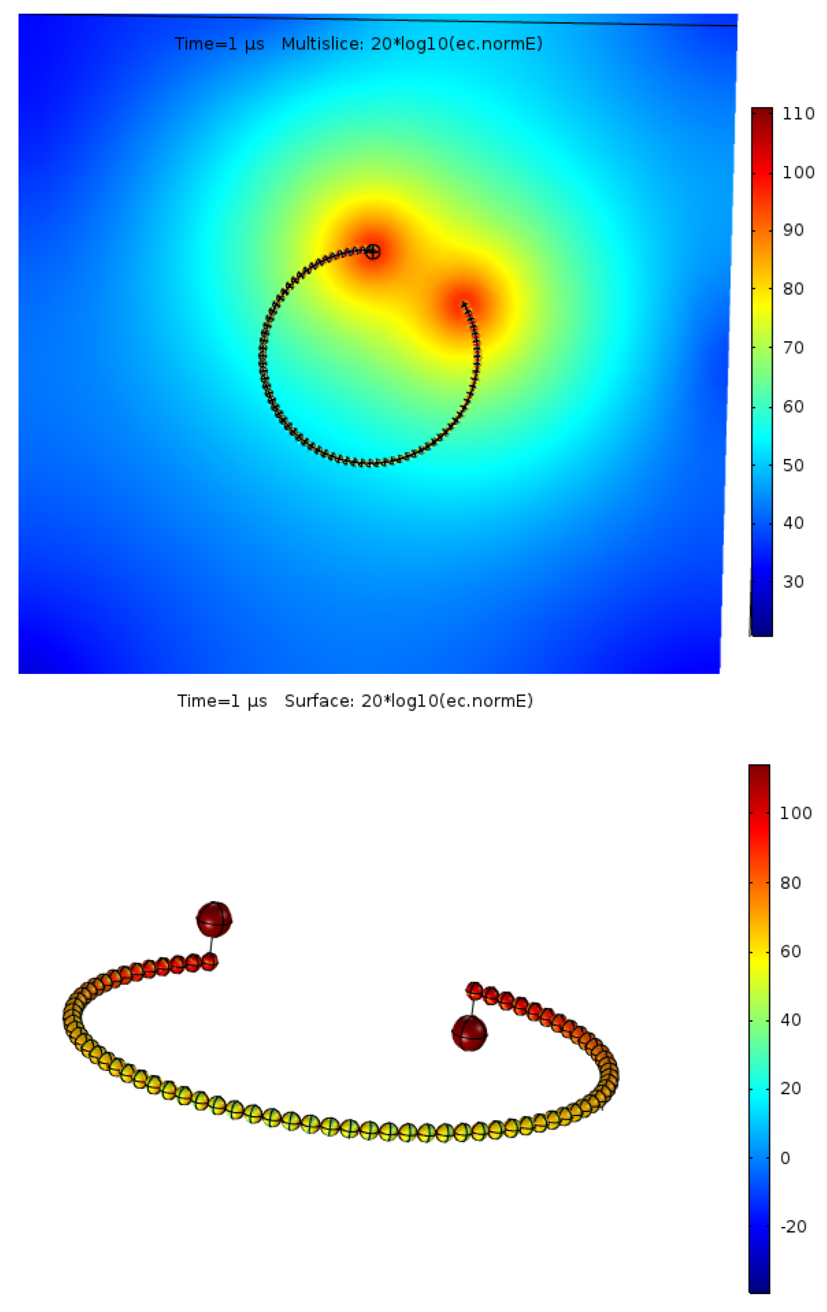
Due to the simplification of the model, the intensity of the electric field in the case of the MCA device is presented at the final stage of the discharge (Figure 6).
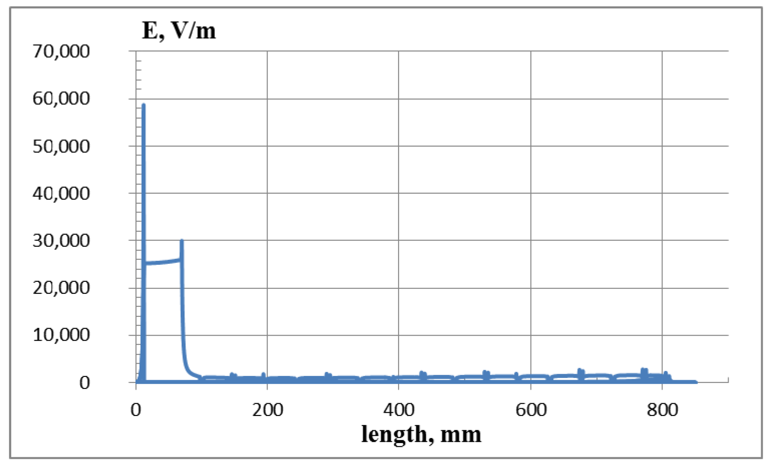
As can be seen from Figure 6, where the intensity level is presented on the MCA device for different time intervals, the maximum values of the electric field intensity are on the level of 100 kV/m to 500 kV/m (Figure 7).
Comparing these results with the results obtained for the simplified LFA (Figure 8), it can be concluded that the intensity on the considered MCA construction elements is much greater than on the LFA electrodes. The maximum values that we have obtained for a simplified loop model of a multi-electrode spark gap are at the level of E = 55 kV/m, which is less than for the MCA. This is due to the structural peculiarities of the chamber system, which differ from LFA with a small number of electrodes placed on the LFA polyethylene surface.
Results of the analysis of the electric field intensity on the electrodes, which are placed on the considered devices, in the case of MCA gave results in the range of 50–100 kV/m (Figure 6). In the case of LFA, it is a comparable level (Figure 8 and Figure 9).
The comparison of the electric field strength distribution in both considered devices shows that for the MCA, values were much more different than for the LFA. For both of them, the highest E value occurred in the surroundings of the electrode with applied high potential.
An exemplary course of the LFA discharge is shown in Figure 9.

4. Discussion

Analyzing the above information, it should be noted that due to its construction, the LFA may not be used in 110 kV grids, because its task is to ensure the development of sliding discharges that do not convert into arcs. However, in the case of 110 kV lines, it would require much longer devices and no present construction solutions for such devices could be found in practice. Therefore, these devices are effective for medium voltage networks. The MCA device, which is able to withstand arcing and which controls the discharge process in a much better way through a higher level of intensity, will provide an effective overvoltage protection of the 110 kV grid.
The use of numerical modeling seems to be a good way to streamline the development of the surge protection device design based on both phenomena: the gliding surface discharges and dividing the main gap into many smaller gaps spread over greater distances. Both methods can cut off the overvoltage pulse and discharge its energy to the ground without an electric arc. For this reason, both the LFA and the MCA can be thought of as non-follow current (NFC) devices, even though each is a type of surge protection device (SPD). Numerical modeling even fits the transients. With some simplification, it is possible to observe the distribution of the electric field in exact time steps even inside the structure of the modeled object, which in fact is not possible without the influence of the measuring device. Further simulations with different adapted conditions or design changes can be a useful tool in the design phase of new SPD concepts.

5. Conclusions

The conducted research allowed for the development of simplified numerical models of LFA and MCA surge protection devices.
The conducted analysis of tests and simulations shows that the devices discussed in the article have comparable properties, whereas due to the specificity of the structure and differences in the method of operation, LFA requires MV and MCA networks in high voltage networks.
The distributions of electric potential and electric field strength obtained from numerical simulations prove the presumptive principles of operation of these devices. In the case of MCA and LFA, it can be seen that the electrodes located along the discussed devices play a key role in the development of the discharge.
At the same time, the intensity on these electrodes is at the level of 2 kV/m for MCA and LFA. The differentiation occurs in the nature of the discharge course—in the case of LFA, the maximum electric field strength occurs on the electrodes of the device, and in the case of MCA, the value of the field strength is comparable along the entire length of the device, excluding the initial and final parts of the device.
The MCA design has the added advantage of being able to greatly enhance the arc cutting processes by using arc quenching chambers between spherical electrodes. There is no such solution in LFA, so the application of the standard LFA structure may be difficult in HV lines with rated voltage above 110 kV.
This article was written as part of an internal grant, “Testing of selected means of protection of overhead lines against atmospheric surges”, from the Warsaw University of Technology supporting scientific activities in the discipline of Automation, Electronics and Electrical Engineering.

Author Contributions

Data curation, M.B.; Formal analysis, M.B.; Funding acquisition, M.B.; Investigation, M.B.; Methodology, M.B.; Project administration, M.B.; Resources, M.B.; Software, M.B.; Supervision, M.B.; Validation, M.B. and Y.K.; Visualization, M.B.; Writing—original draft, M.B. All authors have read and agreed to the published version of the manuscript.

Funding

This research received no external funding.

Institutional Review Board Statement

Not applicable.

Informed Consent Statement

Not applicable.

Data Availability Statement

Not applicable.

Conflicts of Interest

The authors declare no conflict of interest.

References

  1. Ohtaka, T.; Iwata, M.; Tanaka, S.; Goda, Y. Development of an EMTP simulation model of arcing horns interrupting fault current. IEEE Trans. Power Deliv. 2010, 25, 2017–2024. [Google Scholar] [CrossRef]
  2. Hemapala, K.; Gnana Swathika, O.; Dharmadasa, K. Techno-economic feasibility of lightning protection of overhead transmission line with multi-chamber insulator arrestors. Dev. Eng. 2018, 3, 100–116. [Google Scholar] [CrossRef]
  3. Qiao, X.; Zhang, Z.; Jiang, X.; Sundararajan, R.; Ma, X.; Li, X. AC failure voltage of iced and contaminated composite insulators in different natural environments. Int. J. Electr. Power Energy Syst. 2020, 120, 105993. [Google Scholar] [CrossRef]
  4. He, J.; Wang, X.; Yu, Z.; Zeng, R. Statistical analysis on lightning performance of transmission lines in several regions of China. IEEE Trans. Power Deliv. 2015, 30, 1543–1551. [Google Scholar] [CrossRef]
  5. Meng, P.; Yuan, C.; Xu, H.; Wan, S.; Xie, Q.; He, J.; Zhao, H.; Hu, J.; He, J. Improving the protective effect of surge arresters by optimizing the electrical property of ZnO varistors. Electr. Power Syst. Res. 2020, 178, 106041. [Google Scholar] [CrossRef]
  6. Wang, J.; Wang, S.; Cai, L.; Lu, D.; Li, Q.; Zhou, M.; Fan, Y. Observation of induced voltage at the terminal of 10 kV distribution line by nearby triggered lightning. IEEE Trans. Power Deliv. 2020, 35, 1968–1976. [Google Scholar] [CrossRef]
  7. Gu, S.; Wan, S.; Wang, J.; Chen, J.; Li, T. Development and application of ±500 kV DC transmission line arrester in China power grid. IEEE Trans. Power Deliv. 2018, 33, 209–217. [Google Scholar] [CrossRef]
  8. Jiang, Z.; Wu, W.; Wang, B.; Xie, P.; Li, H.; Lin, F. Design and test of 500-kV lightning protection insulator. IEEE Access 2019, 7, 135957–135963. [Google Scholar] [CrossRef]
  9. Wang, B.; Lu, J.; Fang, Z.; Jiang, Z.; Hu, J. Development of anti-thunder composite insulator for distribution line. IEEJ Trans. Electr. Electron. Eng. 2019, 15, 100–107. [Google Scholar] [CrossRef]
  10. Podporkin, G.V.; Sivaev, A.D. Lightning protection of distribution lines by long flashover arresters (LFA). IEEE Trans. Power Deliv. 1998, 13, 814–823. [Google Scholar] [CrossRef]
  11. Borecki, M.; Sobolewski, K. An elimination method for an emergency situation in Gas-insulated switchgear in power grids. IEEE Trans. Power Deliv. 2021, 36, 3724–3732. [Google Scholar] [CrossRef]
  12. Wang, J.F.; Wu, D. Development of an arc-extinguishing lightning protection gap for 35 kV overhead power lines. IET Gen. Transm. Distrib. 2017, 11, 2897–2901. [Google Scholar] [CrossRef]
  13. Hoduń, P.; Borecki, M. Reliability Assessment of MV Power Connections. Energies 2021, 14, 6965. [Google Scholar] [CrossRef]
  14. Qiao, X.; Zhang, Z.; Sundararajan, R.; Jiang, X.; Hu, J.; Fang, Z. The failure arc paths of the novel device combining an arrester and an insulator under different pollution levels. Int. J. Electr. Power Energy Syst. 2021, 125, 106549. [Google Scholar] [CrossRef]
  15. Zhang, Z.; Qiao, X.; Zhang, Y.; Tian, L.; Zhang, D.; Jiang, X. AC flashover performance of different shed configurations of composite insulators under fan-shaped non-uniform pollution. IET High Volt. 2018, 3, 199–206. [Google Scholar] [CrossRef]
  16. He, L.; Gorur, R.S. Source strength impact analysis on polymer insulator flashover under contaminated conditions and a comparison with porcelain. IEEE Trans. Dielectr. Electr. Insul. 2016, 23, 2189–2195. [Google Scholar] [CrossRef]
  17. Qiao, X.; Zhang, Z.; Jiang, X.; Li, X.; He, Y. A new evaluation method of aging properties for silicon rubber material based on microscopic images. IEEE Access 2019, 7, 15162–15169. [Google Scholar] [CrossRef]
  18. PN-EN IEC 60099-8:2018-04; Ograniczniki przepięć. Część 8: Ograniczniki przepięć z tlenków metali z zewnętrznymi iskiernikami szeregowymi (EGLA) do napowietrznych przesyłowych i rozdzielczych linii napięcia przemiennego w sieciach powyżej 1 kV. Available online: https://sklep.pkn.pl/pn-en-iec-60099-8-2018-04e.html (accessed on 7 June 2022).
  19. Podporkin, G.V.; Pilshchikov, V.E.; Sivaev, A.D. On the use of surge arresters for lightning protection of 6–10 kV overhead lines. Cable-News 2009, 23–27. [Google Scholar]
  20. Chalilow, F.H. Protection of 6–35 kV Networks from Surges; Energoatomizdat: St. Petersburg, Russia, 2002; 260p. [Google Scholar]
  21. Borecki, M.; Ciuba, M.; Kharchenko, Y.; Khanas, Y. Main aspects influencing the evaluation of atmospheric overvoltages in high-voltage networks. Bull. Pol. Acad. Sci. Tech. Sci. 2021, 69, e135838. [Google Scholar]
  22. Borecki, M. Risk level analysis in the selected (initial) stage of the project life cycle. Manag. Prod. Eng. Rev. 2020, 11, 104–112. [Google Scholar]
  23. Borecki, M. A Proposed new approach for the assessment of selected operating conditions of the high voltage cable line. Energies 2020, 13, 5275. [Google Scholar] [CrossRef]
  24. Borecki, M.; Ciuba, M.; Kharchenko, Y.; Khanas, Y. Substation reliability evaluation in the context of the stability prediction of power grids. Bull. Pol. Acad. Sci. Tech. Sci. 2020, 68, 769–776. [Google Scholar]
  25. Podporkin, G.V.; En’kin, E.Y.; Pil’shchikov, V.E. The Development of Multichamber Arresters. Russ. Electr. Eng. 2013, 84, 1–5. [Google Scholar] [CrossRef]
Figure 1. 2D model of fragment of a long flashover arrester.
Energies 15 04326 g001
Figure 2. A simplified 3D model of a multi-chambered spark gap.
Energies 15 04326 g002
Figure 3. Voltage application point (potential) in a 3D model of MCA.
Energies 15 04326 g003
Figure 4. Distribution of potential in a simplified 3D model of MCA for time t = 1 µs.
Energies 15 04326 g004
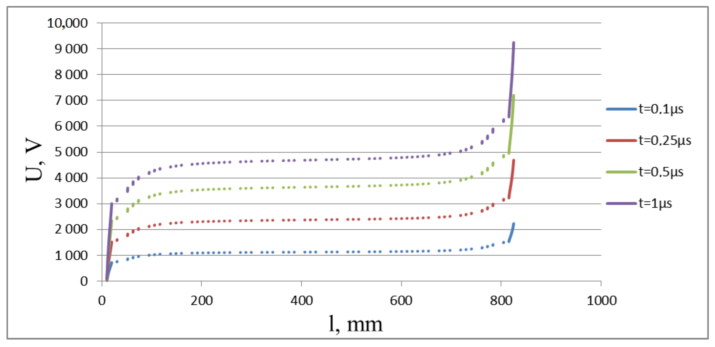
Figure 5. Potential distribution along MCA gaps between electrodes.
Energies 15 04326 g005
Figure 6. The distribution of the electric field intensity in a simplified 3D model of MCA for time t = 1 µs.
Energies 15 04326 g006
Figure 7. Plots of electric field intensity along the MCA structure.
Energies 15 04326 g007
Figure 8. Plots of electric field intensity on the LFA surface.
Energies 15 04326 g008
Figure 9. Development of slip in the 2D LFA model.
Energies 15 04326 g009
Publisher’s Note: MDPI stays neutral with regard to jurisdictional claims in published maps and institutional affiliations.