Abstract
To acquire a satisfying cutting effect during medium-length hole blasting driving of rock tunnels, an improved wedge cutting blasting method with supplementary blasting of the center holes was proposed. Initially, the cavity forming mechanism of the improved cutting method was analyzed theoretically. The results suggested that cutting hole blasting could realize the ejection of rock within the range from free face to critical cutting depth, and hence reduce the restraining force of the center hole blasting, and the supplementary blasting of the center holes could further accomplish the expulsion of the residuary rock. Subsequently, simulation of the improved cutting method was implemented to exhibit the stress wave evolution and reveal the stress field distribution. The simulation results indicated that cutting hole blasting could cause the preliminary failure of the residuary rock, and center hole blasting could strengthen the stress field intensity in 1.8–2.5 m in order to aggravate the destruction of the residuary rock. Hence, the residuary rock could be broken into small fragments that were easy to expel out. Finally, a field application experiment was conducted in a coal mine rock tunnel. Using the improved wedge cutting method instead of the conventional wedge cutting method, the full-face blasting driving efficiency was obviously enhanced and the overall blasting driving expense was significantly reduced, which forcefully confirmed the engineering usefulness of the improved wedge cutting method in the medium-length hole blasting driving of rock tunnels.
1. Introduction
To date, the drilling and blasting method still occupies a dominant position in coal mine underground tunnel driving because of its salient features of convenient operation, strong adaptability, and economical investment, despite the continuous development of mechanical excavators [1,2,3,4]. During the blasting driving of rock tunnels, the main function of cutting blasting is creating an extra free face and rock bulking space for subsequent blasting procedures. Therefore, the selection and design of the cutting blasting method is the key to determining the overall blasting driving efficiency of coal mine rock tunnels [5,6,7,8]. According to the hole layout, the common cutting blasting methods are broadly categorized into parallel-hole and inclined-hole cutting blasting methods, and wedge cutting blasting is the most frequently employed among various inclined-hole cutting methods. Engineering practices prove that the prominent defects of parallel-hole cutting blasting are many cutting holes, high explosive consumption, and a small cavity size [9,10]. Conversely, the conspicuous advantages of the wedge cutting method are few cutting holes, low explosive consumption, and large cavity size [11,12]. Therefore, the wedge cutting method has been the most extensively used cutting blasting method in the full-face blasting driving of coal mine rock tunnels.
Recently, numerous experts and scholars have executed a great deal of research on wedge cutting blasting and have obtained fruitful academic achievements. For instance, based on full consideration of the failure modes of different cavity surfaces, Dai and Du [13] proposed a computing method of wedge cutting parameters, and further discussed the influences of rock hardness and explosive performance on the design of cutting parameters. According to the difference between blasting stress wave and detonation gas, Wang et al. [14] divided the cavity forming process into the rock damage stage and rock throwing stage, and investigated the cavity forming mechanism by using a simplified mechanical model. To investigate the influence of cutting hole angle symmetry on the wedge cutting results, Liang et al. [15] performed similar simulation experiments to analyze the cutting effect from the aspects of cavity size and blasting hole utilization, and concluded that the symmetrical arrangement of cutting hole angles would be conducive to the full utilization of blasting energy. Through laboratory model tests, Pu et al. [16] obtained the factors affecting the wedge cutting effect, and further computed and sequenced the gray relational grade of these factors. Then, they found that the cutting hole angle was the primary factor affecting the cutting blasting results, with a high gray relational grade of 2.39. Yang et al. [17] concretely investigated the effect of the cutting hole angle on the cutting cavity size and rock fragment size based on the model test data, and obtained the optimal cutting hole angle that could be used to guide the design of the cutting parameters. Because of the rapidity and complexity of the blasting process, the experimental research has some deficiencies such as a huge expense, long period, and low accuracy, and the theoretical calculation can only solve some simplified problems [18,19]. With the fast progress and development of computer numerical technology, the numerical technique has become a practicable means to study the cutting blasting mechanisms of rock tunnels. For example, using the nonlinear analysis platform LS-DYNA, Xie et al. [20] simulated the damage development process of cutting blasting under different crustal stress, and further optimized the design of cutting blasting in deep rock. Hu et al. [21] obtained the cutting cavity extension by introducing the rock damage criterion into the LS-DYNA, and thus demonstrated the effectiveness of wedge cutting blasting in the blasting driving of mine rock tunnels. Cheng et al. [22] also simulated the stress wave propagation of wedge cutting blasting under different explosive diameters, and further analyzed the influence of the explosive diameter on stress distribution features and cutting cavity formation. According to the above review, the current research mainly focuses on the blasting mechanism, charge parameters, and hole parameters of the conventional wedge cutting method.
Currently, the increasing demand for coal energy resources has put forward higher requirements for the driving speed of coal mine rock tunnels. However, the blasting diving efficiency of coal mine rock tunnels in China is always at a low speed of 75 m/month, which cannot maintain the balance between mining and driving and seriously restricts the productivity of underground coal mines. Accordingly, traditional shallow hole blasting with a hole depth of less than 1.8 m has become inopportune, and the medium-length hole blasting with a hole depth of more than 2.0 m has turned into an inevitable and judicious choice [23,24]. However, the restraining force from the surrounding rock will considerably increase with the hole depth. Because of the low power of the permitted explosives for coal mine, the powerful restraining force will inevitably deteriorate the cutting blasting effect; that is, only a small extra free face and insufficient rock bulking space can be created after cutting blasting [25], which will lead to small cyclical footage and low blasting hole utilization in the subsequent blasting driving procedures.
Consequently, in the present paper, an improved wedge cutting blasting method with supplementary blasting of the center holes was proposed to achieve a good cutting blasting effect in the medium-length hole blasting diving of coal mine rock tunnels. Initially, the cavity forming mechanism for the improved cutting method was analyzed theoretically. Subsequently, a numerical analysis was performed to display the evolution process of the stress wave and to reveal the distribution characteristics of the stress field. Ultimately, field application experiment was conducted in a coal mine rock tunnel to examine the engineering usefulness of the improved wedge cutting method.
2. Theoretical Analysis of Cavity Forming Mechanism
2.1. Analysis of Restraining Force
Existing research results have indicated that the restraining force from the surrounding rock would increase with the hole depth (or cutting depth) during single-face blasting such as cutting blasting. However, because of the limitations of research methods and test means, it is extremely difficult to evaluate the restraining force quantitatively and accurately. Previous studies [26,27] have pointed out that the increasing rate of the restraining force could increase with the hole depth during single-hole charge blasting. Therefore, with reference to their research achievements, the conventional wedge cutting blasting was equivalent to single-hole charge blasting, and the variation curve of the restraining force with the cutting depth was plotted and is shown in Figure 1. Here, the curve A0A1A2A3 corresponds to the change law of the restraining force for conventional wedge cutting blasting, and H2 and F2 represent the critical cutting depth and the critical restraining force, respectively. The interpretation of H2 and F2 is that if the actual cutting depth is less than or equal to the critical cutting depth H2, the cavity forming force can always overcome the actual restraining force lower than or equal to the critical restraining force F2, and then the rock in the cutting cavity can be completely ejected.
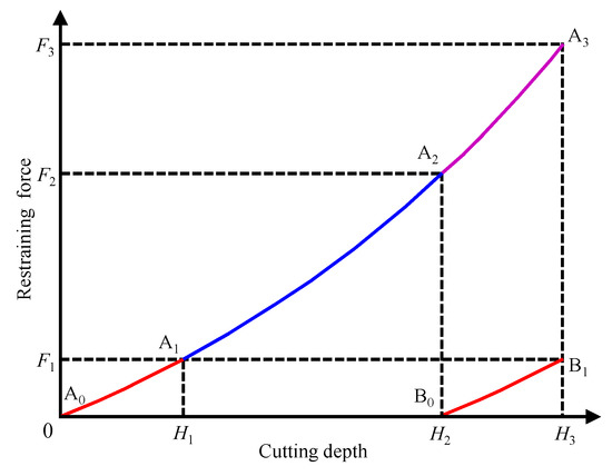
Figure 1.
Variation curve of the restraining force with cutting depth.
As indicated in Figure 1, during conventional wedge cutting blasting, the restraining force would gradually increase with the cutting depth along the curve A0A1A2A3. Because the design cutting depth H3 was greater than the critical cutting depth H2, the restraining force was always higher than the critical restraining force F2 in the range of H2–H3. Therefore, the rock in the range of 0–H2 could be thrown out, while the rock within the range of H2–H3 could be stuck in the cutting cavity. Eventually, only a small extra free face and insufficient rock bulking space could be provided for the subsequent blasting procedures, which would exert a detrimental effect on the overall driving efficiency.
Subsequently, it was assumed that supplementary blasting was performed at the bottom of the cutting cavity. As the rock in the range of 0–H2 had been fully ejected, a new free face could be formed at the cutting depth of H2, which would lead to a redistribution of the restraining force in the range of H2–H3. The restraining force would return to zero at a cutting depth of H2 and would continue to increase along the curve B0B1 in the range of H2–H3, and curve B0B1 was consistent with the curve A0A1, as illustrated in Figure 1. The residuary cutting depth in the range of H2–H3 was equal to H1, and H1 was less than the critical cutting depth H2, which means that the maximum restraining force during supplementary blasting was equal to F1, and F1 was lower than the critical restraining force F2. Therefore, the residuary rock within the range of H2–H3 could be completely ejected after the supplementary blasting. Eventually, a large extra free face and sufficient rock bulking space could be provided for the subsequent blasting procedures, which would have a beneficial effect on the overall blasting tunneling efficiency.
2.2. Improved Cutting Method and Cavity Forming Process
Based on the analysis of the restraining force, an improved wedge cutting blasting method with supplementary blasting of the center holes could be developed. As illustrated in Figure 2, similar to the conventional wedge cutting method, cutting holes were symmetrically fixed on the left and right sides of the heading face, and the angle between the cutting holes and the heading face was within the range of 75–85°. Most of the explosives required for cutting blasting were filled in the cutting holes and were detonated by the first-stage detonators. Different from the conventional wedge cutting method, the center holes perpendicular to the heading face were arranged in the middle area of the heading face, and its depth was the same as the vertical depth of the cutting holes. A small amount of explosives were loaded at the bottom of the center holes and detonated by the second-stage detonators. The forming procedure of the cutting cavity is shown in Figure 3.
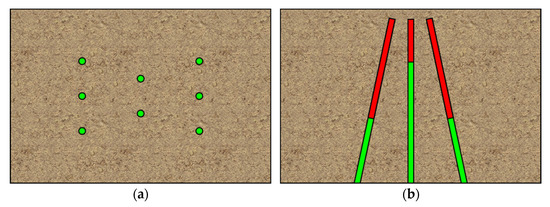
Figure 2.
Hole layout of the improved wedge cutting method: (a) front view and (b) top view.
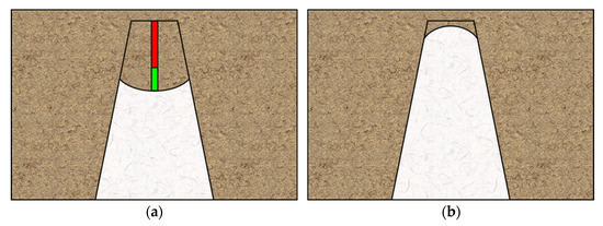
Figure 3.
Cavity forming procedure: (a) cutting hole blasting and (b) center hole blasting.
After early blasting of the cutting holes, the rock in the range from the free face to the critical cutting depth formed rock fragments under the intensive blasting load, and then these rock fragments were ejected out from the cutting cavity under the push action of the detonation gas. During the medium-length hole blasting, the rock at the bottom of the cutting cavity could not be thrown out under the powerful restraining force from the surrounding rock, but it would be preliminarily destroyed by the blasting stress wave from the cutting holes. Furthermore, a new free face could be created to reduce the restraining force of the center hole blasting. The cavity created by the cutting hole blasting is shown in Figure 3a. After supplementary blasting of the center holes, because of the preliminary destruction and new free face caused by the early blasting of the cutting holes, the residuary rock easily formed rock fragments under the blasting stress wave of the center holes, and then these rock fragments could be ejected almost completely under the push action of the detonation gas. The cavity generated by the center hole blasting is presented in Figure 3b.
Compared with the conventional wedge cutting method, the process of cutting blasting was changed from a one-step blasting pattern to a two-step blasting pattern. The early blasting of the cutting holes and the supplementary blasting of the center holes were viewed as the first step blasting and second step blasting, respectively. For the first step, early blasting of the cutting holes could accomplish most of the cavity forming task and could reduce the restraining force of the center hole blasting. For the second step, supplementary blasting of the center holes could complete the rest of the cavity forming task to achieve a satisfying cutting effect.
3. Numerical Simulation and Analysis
3.1. Numerical Model Descriptions
A three-dimensional numerical model with dimensions of 4000 mm × 3000 mm × 3000 mm (length × width × height) was erected using an eight-node solid element SOLID164 in ANSYS/LS-DYNA, as shown in Figure 4. Two center holes perpendicular to the free face were arranged on the middle area of the heading face, and the space, depth, and charge length of the center holes were 400, 2500, and 660 mm, respectively. Six wedge cutting holes were symmetrically arranged on the left and right sides of the heading face; the angle between cutting holes and heading face was 77.5°; and the space, top space, bottom space, vertical depth, and charge length of the cutting holes were 400, 1500, 400, 2500, and 1320 mm, respectively. In addition, 40 mm diameter holes and 35 mm diameter explosive sticks were adopted in all of the blasting holes. The geometrical parameters of the numerical model were taken from the blasting parameters of the later field application experiments.
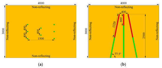
Figure 4.
Numerical calculation model (unit: mm): (a) front view and (b) vertical view.
In this simulation, a reverse initiation pattern was performed at all of the blasting holes, and the cutting holes and center holes were initiated at 0 and 1000 µs, respectively. Through several tentative simulations, the time interval of 1000 µs ensured that the peak stresses induced by the cutting holes and the center holes were independent of each other. Setting the initiation points and initiation times was completed using the keyword *INITIAL_DETONATION. To effectively avoid the negative influence of stress wave reflection from the artificial boundary on the precision of the calculation results, non-reflecting boundaries were exerted into the rock model surfaces, except for the heading face [28,29,30]. In addition, the convergence tests of the mesh size were implemented before the formal simulation. During the tests, the number of elements continued to increase until the peak stress difference at the same stress monitoring point between two consecutive tests was less than 5% [31,32,33]. The meshing of the rock model is shown in Figure 5.
Figure 5.
Meshing of the rock model.
3.2. Algorithms and Material Models
In ANSYS/LSDYNA, the algorithms used to describe the continuous media mainly include Euler, Lagrange, and ALE (Arbitrary−Lagrange−Euler) [34,35], and the latter two algorithms were used in this study. The Lagrange algorithm is more effective for the description of solid media [36,37]; thus, it was adopted to simulate the rock and stemming. The ALE algorithm is well suited to describing the fluid media [38]; thus, it was used to simulate the explosive and air. Furthermore, the transfer problem of mechanical information between the fluid and solid media was solved by defining the fluid−structure interaction algorithm.
It is well known that the determination of the blasting load is very important for simulating the blasting process. To achieve high accuracy, the *MAT_HIGH_EXPLOSIVE_BURN material model was adopted for the explosive, and the detonation pressure resulting from the release of explosive energy was described by the JWL state equation [39,40,41]. As for the other materials included in this study, the *MAT_NULL material model and linear polynomial state equation were selected for the air [42]. The dynamic response of brittle materials subjected to high energy explosive loads is a complex rate-dependent process [43]; thus, the *MAT_PLASTIC_KINEMATIC material model considering the rate dependence was adopted to simulate the rock [44,45,46]. Moreover, the nonlinear deformation process of stemming was described by the *MAT_SOIL_AND_FORM material model. In this study, except for the mechanical parameters of the rock that were tested and obtained through laboratory tests, the main parameters of the other three materials were selected from the existing literature [47,48,49]. The main constitutive parameters of the above four materials are given in Table 1, Table 2, Table 3 and Table 4.

Table 1.
Main constitutive parameters of the explosive.
Table 2.
Main constitutive parameters of air.
Table 3.
Main constitutive parameters of rock.
Table 4.
Main constitutive parameters of stemming.
3.3. Simulation Results and Discussions
3.3.1. Dynamic Evolution of Stress Wave
The keyword file containing the above model and material information was submitted to the solver LS-DYNA. Then, the rock model was partitioned along the horizontal symmetric plane by the post-processing software LS-PREPOST to clearly present the dynamic evolution process of the stress wave. The dynamic developments of the stress wave after the charge detonation in cutting holes and center holes are presented in Figure 6 and Figure 7, respectively.
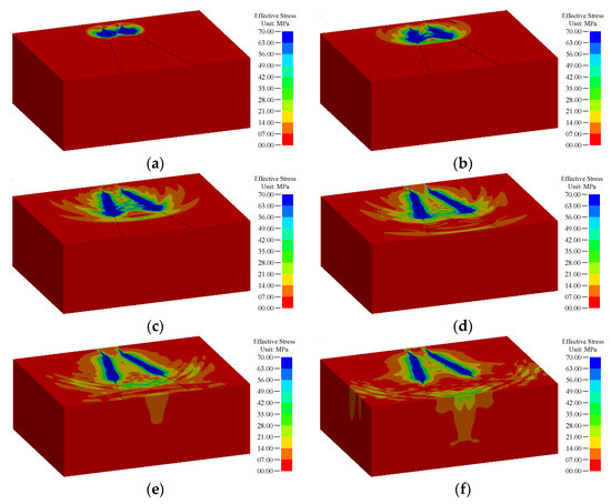
Figure 6.
Dynamic evolution process of stress wave after charge detonation in cutting holes: (a) 080 µs, (b) 160 µs, (c) 320 µs, (d) 470 µs, (e) 600 µs, and (f) 800 µs.
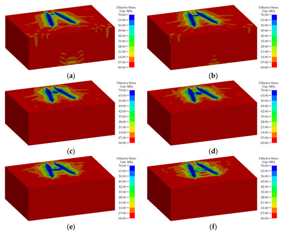
Figure 7.
Dynamic evolution process of stress wave after charge detonation in center holes: (a) 1050 µs, (b) 1100 µs, (c) 1150 µs, (d) 1200 µs, (e) 1250 µs, and (f) 1300 µs.
As illustrated in Figure 6, when the explosive was detonated in the cutting holes, a huge amount of chemical energy was released in order to induce the stress wave. With the rapid detonation reaction of the explosive in the cutting holes, the induced blasting stress wave propagated towards the heading face. Subsequently, the stress waves derived from the cutting holes were superimposed on each other in the middle zone of the blasting model, which would promote the destruction of rock in the cutting cavity. At 320 µs, the detonation transmission of the explosive in each of the cutting holes was completed. However, the blasting stress wave continued to propagate to the heading face and was reflected as the tensile stress wave after reaching the heading face. Because of the low tensile strength of various brittle materials such as rock, the tensile stress wave would cause great tensile damage to the rock close to the heading face [50]. After that, the forward-propagation compression wave met the backward-propagation tensile wave to form a complex stress environment, which would increase the damage level of the rock in the cutting cavity. The above stress wave evolution after the charge detonation of cutting holes was basically in accordance with the relevant numerical simulation results of the conventional wedge cutting method [22].
As shown in Figure 7, when the explosive located in the center holes was detonated at 1000 µs, a large amount of chemical energy was also released to generate the stress wave. With the rapid detonation reaction of the explosive in the center holes, the generated blasting stress wave propagated towards the heading face along the center hole in a circular wave front, and was superimposed with the stress wave remaining from the cutting holes to aggravate the destruction of the rock at the bottom of the cutting cavity. At 1150 µs, the detonation transmission of the explosive in each center hole was completed, and the blasting stress wave still continued to propagate towards the heading face.
From Figure 6 and Figure 7, the rock in the cutting cavity could be subjected to the blasting stress waves from the cutting holes and the center holes successively. Owing to the deficiency of the numerical simulation, the throwing process of the rock could not be obtained. However, in fact, after the cutting hole blasting, the rock in the range from the free face to critical cutting depth could be thrown out and would not be subjected to the stress wave of the center holes. In contrast, because of the powerful restraining force, the residuary rock in the range from the critical cutting depth to the design cutting depth could not be expelled in practice. Therefore, only the residuary rock would be subjected to the stress waves generated by the cutting holes and the center holes successively.
3.3.2. Distribution Features of Stress Field
In order to intuitively study the specific influence of center hole blasting on the distribution features of the stress field in the cutting cavity, a monitoring line perpendicular to the heading face was set in the middle of the rock numerical model. A monitoring point was fixed every 0.1 m on the monitoring line, and there were 26 stress monitoring points in the design cutting depth range of 0–2.5 m. Then, the stress−time curves of these stress monitoring points were output, and that of the typical stress monitoring points at cutting depths of 0.7, 1.3, 1.9, and 2.4 m are presented in Figure 8.
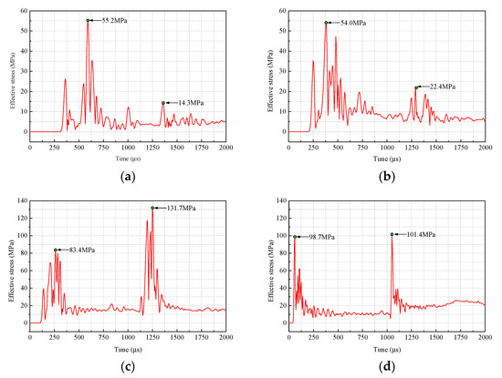
Figure 8.
Stress−time curves of typical stress monitoring points: (a) 0.7 m, (b) 1.3 m, (c) 1.9 m, and (d) 2.5 m.
As shown in Figure 8, under the blasting stress waves caused by the cutting holes and the center holes, two peak stresses appeared successively on the stress−time curve of each stress monitoring point. Nevertheless, after early blasting of the cutting holes, the rock in the range from the free face to critical cutting depth could be thrown out and would not be subjected to the stress wave of the center holes, and the rock in the range from the critical cutting depth to the design cutting depth could not be expelled and would be subjected to two stress waves from the cutting holes and the center holes. Therefore, the second peak stress did not exist at the stress monitoring points in the range from the free face to critical cutting depth, and the first and second peak stresses actually existed at the stress monitoring points in the range from the critical cutting depth to the design cutting depth.
According to the subsequent field application experiment, an average cyclical footage of 1.79 m could be acquired using the conventional wedge cutting method, and the critical cutting depth was conservatively estimated to be about 1.8 m. Accordingly, after early blasting of the cutting holes, the rock in the range of 0–1.8 m was ejected out and would not be affected by the stress wave of the center holes, while the rock in the range of 1.8–2.5 m was confined in the cutting cavity and would be subjected to two stress waves from the cutting holes and the center holes. This also means that the second peak stress did not exist in 0–1.8 m, while both the first and second peak stresses existed within 1.8–2.5 m.
Both the first and second peak stresses were extracted to draw the variation curve of the peak stress with the cutting depth, as shown in Figure 9. It could be observed that the first peak stress substantially increased with the cutting depth and reached a maximum value of 102.9 MPa at 2.2 m. The second peak stress increased initially and decreased afterwards, and reached a maximum value of 149.0 MPa at 2.0 m. Nevertheless, because the rock within 0–1.8 m was not subjected to the stress wave of the center holes, only the range of 1.8–2.5 m was taken for further contrastive analysis.
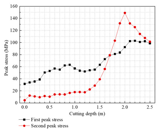
Figure 9.
Variation curve of the peak stress with the cutting depth.
From Figure 9, in the range of 1.8–2.5 m, the first peak stresses were greater than the compressive strength of the rock. Although the residuary rock was stuck at the bottom of the cutting cavity as a result of the powerful restraining force after the cutting hole blasting, it would be preliminarily destroyed by the stress wave produced by the cutting holes, thus reducing the difficulty of the center hole blasting. Also in this range, the second peak stress was always greater than the first peak stress. The maximum values of the first peak stresses and second peak stresses were 102.9 and 149.0 MPa, respectively, and the latter was 1.45 times that of the former. The average values of the first peak stresses and the second peak stresses were 95.5 and 119.7 MPa, respectively, and the latter was 1.25 times of the former. It was believed that the stress field intensity in the range of 1.8–2.5 m could be obviously increased after center hole blasting, which was conductive to aggravating the destruction of the residuary rock. Consequently, under the successive action of two stress waves, the residuary rock could be broken into small fragments that were easy to throw out, thus forming a cutting cavity in line with the design size.
4. Field Application Experiment
4.1. Project Overview
To investigate the engineering effectiveness of the improved wedge cutting method with supplementary blasting of the center holes, the conventional wedge cutting method and improved wedge cutting method were applied into blasting driving in the same coal mine rock tunnel. The same rock tunnel could minimize the harmful influence of geological conditions on the reliability of test results as much as possible. The rock tunnel was located in the Pansan Coal mine, Huainan, China, which adopted a straight wall arch section, with a height of 3.65 m, a width of 4.7 m, and an area of 14.79 m2. The rock strata that the tunnel passed through were sandstone, with a compressive strength of 78.1 MPa and a tensile strength of 6.4 MPa.
4.2. Design of Blasting Scheme
In the field application experiment, two types of drill bits with diameters of 40 mm and 32 mm were selected for the drilling operations. The permitted water-gel explosive for coal mine, including two specifications, 35 mm × 330 mm × 350 g (diameter × length × weight) and 29 mm × 430 mm × 310 g, were used as the blasting material. The center holes and cutting holes employed Φ 40 mm (Φ represents the diameter) blasting holes and Φ 35 mm explosive sticks, and Φ 32 mm blasting holes and Φ 29 mm explosive sticks were used for the other holes. In addition, the coal mine permitted electric detonator with five delay stages was adopted as the detonation device.
Prior to the research and development of the improved wedge cutting method, the conventional wedge cutting method had been adopted in blasting site for a long time. Therefore, the blasting design using the conventional wedge cutting method was regarded as the original scheme, and that using the improved wedge cutting method was considered as the optimized scheme. Then, the blasting parameters of the original and optimized schemes are provided in Table 5 and Table 6, and the blasting hole layouts of the original and optimized schemes are indicated in Figure 10 and Figure 11.
Table 5.
Blasting parameters of the original scheme.
Table 6.
Blasting parameters of the optimized scheme.
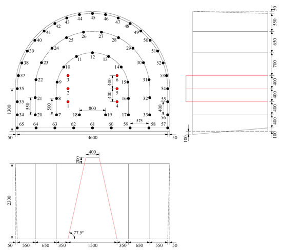
Figure 10.
Blasting hole layout of the original scheme (unit: mm).
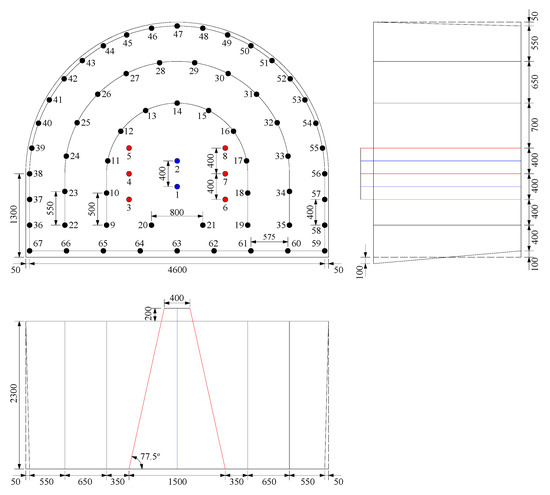
Figure 11.
Blasting hole layout of the optimized scheme (unit: mm).
4.3. Experimental Results
During the field experiment, because of the limitation of measuring means, it was very difficult to detect and evaluate the cutting effect separately without affecting the whole engineering schedule. Accordingly, the cutting blasting effect could usually be indirectly reflected by the final blasting results, such as the cyclical footage, blasting hole utilization, specific explosive consumption, and specific detonator consumption. The statistical data of the final blasting results under the two blasting schemes are shown in Table 7 and Table 8.
Table 7.
Statistical data of the final blasting results for the original scheme.
Table 8.
Statistical data of the final blasting results for the optimized scheme.
As shown in Table 7, when the conventional wedge cutting method was employed for full-face control blasting, the average values of the cyclical footage, blasting hole utilization, specific explosive consumption, and specific detonator consumption were 1.79 m, 77.8%, 2.12 kg·m−3, and 2.46 PCS·m−3, respectively. As indicated in Table 8, when the improved wedge cutting blasting method was adopted for full-face blasting driving, the average values of cyclical footage, blasting hole utilization, specific explosive consumption, and specific detonator consumption were 2.19 m, 95.2%, 1.78 kg·m−3, and 2.07 PCS·m−3, respectively. Compared with the conventional wedge cutting method, the improved wedge cutting method increased the average cyclical footage and average blasting hole utilization by 0.40 m and 17.4%, and reduced the average specific explosive consumption and average specific detonator consumption by 0.34 kg·m−3 and 0.39 PCS·m−3, respectively. The improvement in overall blasting driving efficiency and the reduction in overall blasting driving expense indirectly indicated that the improved wedge cutting method could achieve a satisfying cutting effect and had well engineering applicability in the medium-length hole blasting driving of rock tunnels.
5. Conclusions
- (1)
- The theoretical analysis indicated that the rock in the range from the free face to critical cutting depth could be ejected out after the cutting hole blasting, which reduced the restraining force of the center hole blasting, and then the center hole blasting could further complete the expulsion of residuary rock to achieve a satisfying cutting effect.
- (2)
- The numerical simulation visually presented the dynamic evolution of the stress wave for the improved wedge cutting method. In 1.8–2.5 m, the residuary rock suffered from the stress waves generated by the cutting holes and the center holes successively. The stress field with a low intensity induced by the cutting hole blasting could cause the preliminary failure of the residuary rock, and the stress field with a high intensity generated by the center hole blasting could aggravate the destruction of the residuary rock, which was conductive to breaking the residuary rock into small fragments that were easily thrown out, hence forming a cutting cavity meeting the design size.
- (3)
- In comparison with the conventional wedge cutting method, the improved wedge cutting method attained an increase in the average cyclical footage of 0.40 m and the blasting hole utilization of 17.4%, and a decrease in the average specific explosive consumption of 0.34 kg·m−3 and the average specific detonator consumption of 0.39 PCS·m−3, which convincingly validated the engineering applicability of the improved wedge cutting method in the rock tunnel blasting driving.
Author Contributions
Conceptualization, B.C. and Q.Z.; methodology, B.C.; validation, B.C., H.W. and Q.Z.; formal analysis, B.C. and Q.Z.; investigation, B.C., H.W., Q.Z., M.W., P.G. and N.L.; data curation, Q.Z.; writing—original draft preparation, B.C.; writing—review and editing, B.C. All authors have read and agreed to the published version of the manuscript.
Funding
This study was funded by the National Natural Science Foundation of China (nos. 51374012 and 51404010).
Institutional Review Board Statement
Not applicable.
Informed Consent Statement
Not applicable.
Data Availability Statement
The data used to support the findings of this study are included within the article.
Conflicts of Interest
The authors declare no conflict of interest.
References
- Zare, S.; Bruland, A.; Rostami, J. Evaluating D&B and TBM tunnelling using NTNU prediction models. Tunn. Undergr. Space Technol. 2016, 59, 55–64. [Google Scholar]
- Costamagna, E.; Oggeri, C.; Segarra, P.; Castedo, R.; Navarro, J. Assessment of contour profile quality in D&B tunnelling. Tunn. Undergr. Space Technol. 2018, 75, 67–80. [Google Scholar]
- Ji, L.; Zhou, C.B.; Lu, S.W.; Jiang, N.; Li, H.B. Modeling study of cumulative damage effects and safety criterion of surrounding rock under multiple full-face blasting of a large cross-section tunnel. Int. J. Rock Mech. Min. Sci. 2021, 147, 104882. [Google Scholar] [CrossRef]
- Chandrakar, S.; Paul, P.S.; Sawmliana, C. Influence of void ratio on “Blast Pull” for different confinement factors of development headings in underground metalliferous mines. Tunn. Undergr. Space Technol. 2021, 108, 103716. [Google Scholar] [CrossRef]
- Zare, S.; Bruland, A. Comparison of tunnel blast design models. Tunn. Undergr. Space Technol. 2006, 21, 533–541. [Google Scholar] [CrossRef]
- Zhao, Z.Y.; Zhang, Y.; Bao, H.R. Tunnel blasting simulations by the discontinuous deformation analysis. Int. J. Comput. Methods 2011, 8, 277–292. [Google Scholar] [CrossRef]
- Zuo, J.J.; Yang, R.S.; Xiao, C.L. Model test of empty hole cut blasting in coal mine rock drivage. J. Min. Sci. Technol. 2018, 3, 335–341. [Google Scholar]
- Zhang, H.; Li, T.C.; Wu, S.; Zhang, X.T.; Gao, W.L.; Shi, Q.P. A study of innovative cut blasting for rock roadway excavation based on numerical simulation and field tests. Tunn. Undergr. Space Technol. 2022, 119, 104233. [Google Scholar] [CrossRef]
- Cardu, M.; Seccatore, J. Quantifying the difficulty of tunneling by drilling and blasting. Tunn. Undergr. Space Technol. 2016, 60, 178–182. [Google Scholar] [CrossRef]
- Ding, Z.; Jia, J.; Li, X.; Li, J.; Li, Y.; Liao, J. Experimental study and application of medium-length hole blasting technique in coal-rock roadway. Energy Sci. Eng. 2019, 8, 1554–1566. [Google Scholar] [CrossRef]
- Shapiro, V.Y. Efficiency of cut configuration in driving tunnels with a set of deep blast holes. Sov. Min. Sci. 1989, 25, 379–386. [Google Scholar] [CrossRef]
- Zhang, Z.R.; Yang, R.S. Multi-step cutting technology and its application in rock roadways. Chin. J. Rock Mech. Eng. 2019, 38, 551–559. [Google Scholar]
- Dai, J.; Du, X.L. Research on blasting parameters of wedge-shaped cutting for rock tunnel. Min. Res. Dev. 2011, 32, 90–93. [Google Scholar]
- Wang, Z.K.; Gu, X.W.; Zhang, W.L.; Xie, Q.K.; Xu, X.C.; Wang, Q. Analysis of the cavity formation mechanism of wedge cut blasting in hard rock. Shock Vib. 2019, 2019, 1828313. [Google Scholar] [CrossRef]
- Liang, W.M.; Wang, Y.X.; Chu, H.B.; Yang, X.L. Study on effect of symmetry of wedge shaped cutting hole angle on cut blasting. Met. Mine 2009, 38, 21–24. [Google Scholar]
- Pu, C.J.; Liao, T.; Xiao, D.J.; Wang, J.Q.; Jiang, R. Grey relation analysis of influence factors on rock tunnel wedge-shaped cut blasting. Ind. Miner. Processing 2016, 45, 34–38. [Google Scholar]
- Yang, D.Q.; Wang, X.G.; Wang, Y.J.; An, H.M.; Lei, Z. Experiment and analysis of wedge cutting angle on cutting effect. Adv. Civ. Eng. 2020, 2020, 5126790. [Google Scholar] [CrossRef]
- Sazid, M.; Singh, T.N. Two-dimensional dynamic finite element simulation of rock blasting. Arab. J. Geosci. 2013, 6, 3703–3708. [Google Scholar] [CrossRef]
- Zehtab, B.; Salehi, H. Finite-element-based monte carlo simulation for sandwich panel-retrofitted unreinforced masonry walls subject to air blast. Arab. J. Sci. Eng. 2020, 45, 3479–3498. [Google Scholar] [CrossRef]
- Xie, L.X.; Lu, W.B.; Zhang, Q.B.; Jiang, Q.H.; Chen, M.; Zhao, J. Analysis of damage mechanisms and optimization of cut blasting design under high in-situ stresses. Tunn. Undergr. Space Technol. 2017, 66, 19–33. [Google Scholar] [CrossRef]
- Hu, J.H.; Yang, C.; Zhou, K.P.; Zhou, B.R.; Zhang, S.G. Temporal-spatial evolution and application of blasting cavity of single wedge cutting. J. Cent. South Univ. 2017, 48, 3309–3315. [Google Scholar]
- Cheng, B.; Wang, H.B.; Zong, Q.; Xu, Y.; Wang, M.X.; Zheng, Q.Q.; Li, C.J. A study on cut blasting with large diameter charges in hard rock roadways. Adv. Civ. Eng. 2020, 2020, 8873412. [Google Scholar] [CrossRef]
- Zong, Q.; Liu, Q.H. Application research on cutting technology of mid-deep hole blasting in coal mine rock tunnel. Blasting 2010, 27, 35–39. [Google Scholar]
- Yang, R.S.; Zhang, Z.R.; An, C.; Zheng, C.D.; Ding, C.X.; Xiao, C.L. Discussion on ultra-deep depth problem of slot hole in blasting excavation of rock roadway in coal mine. Coal Sci. Technol. 2020, 48, 10–23. [Google Scholar]
- Ding, C.X.; Yang, R.S.; Zheng, C.D.; Yang, L.Y.; He, S.L.; Feng, C. Numerical analysis of deep hole multi-stage cut blasting of vertical shaft using a continuum-based discrete element method. Arab. J. Geosci. 2021, 14, 1086. [Google Scholar] [CrossRef]
- Zong, Q. Preliminary investigations into deep-hole millisecond delay-action blasting. J. Huainan Min. Inst. 1992, 12, 18–22. [Google Scholar]
- Yang, R.S.; Zheng, C.D.; Yang, L.Y.; Zuo, J.J.; Cheng, T.L.; Ding, C.X.; Li, Q. Study of two-step parallel cutting technology for deep-hole blasting in shaft excavation. Shock Vib. 2021, 2021, 8815564. [Google Scholar] [CrossRef]
- Liu, K.; Li, Q.Y.; Wu, C.Q.; Li, X.B.; Li, J. A study of cut blasting for one-step raise excavation based on numerical simulation and field blast tests. Int. J. Rock Mech. Min. Sci. 2018, 109, 91–104. [Google Scholar] [CrossRef]
- Chen, M.; Ye, Z.W.; Lu, W.B.; Wei, D.; Yan, P. An improved method for calculating the peak explosion pressure on the borehole wall in decoupling charge blasting. Int. J. Impact Eng. 2020, 146, 103695. [Google Scholar] [CrossRef]
- Jiang, N.; Zhu, B.; He, X.; Zhou, C.B.; Luo, X.D.; Wu, T.Y. Safety assessment of buried pressurized gas pipelines subject to blasting vibrations induced by metro foundation pit excavation. Tunn. Undergr. Space Technol. 2020, 102, 103448. [Google Scholar] [CrossRef]
- Blair, D.P. The free surface influence on blast vibration. Int. J. Rock Mech. Min. Sci. 2015, 77, 182–191. [Google Scholar] [CrossRef]
- Yang, J.H.; Lu, W.B.; Li, P.; Yan, P. Evaluation of rock vibration generated in blasting excavation of deep-buried tunnels. KSCE J. Civ. Eng. 2018, 22, 2593–2608. [Google Scholar] [CrossRef]
- Hajibagherpour, A.R.; Mansouri, H.; Bahaaddini, M. Numerical modeling of the fractured zones around a blasthole. Comput. Geotech. 2020, 123, 103535. [Google Scholar] [CrossRef]
- Park, D.; Jeon, S. Reduction of blast-induced vibration in the direction of tunneling using an air-deck at the bottom of a blasthole. Int. J. Rock Mech. Min. Sci. 2010, 47, 752–761. [Google Scholar] [CrossRef]
- Kim, J.G.; Song, J.J. Abrasive water jet cutting methods for reducing blast-induced ground vibration in tunnel excavation. Int. J. Rock Mech. Min. Sci. 2015, 75, 147–158. [Google Scholar] [CrossRef]
- Jang, H.; Handel, D.; Ko, Y.; Yang, H.S.; Miedecke, J. Effects of water deck on rock blasting performance. Int. J. Rock Mech. Min. Sci. 2018, 112, 77–83. [Google Scholar] [CrossRef]
- Hu, Y.G.; Lu, W.B.; Chen, M.; Yan, P.; Yang, J.H. Comparison of blast-induced damage between presplit and smooth blasting of high rock slope. Rock Mech. Rock Eng. 2014, 47, 1307–1320. [Google Scholar] [CrossRef]
- Cheng, B.; Wang, H.B.; Zong, Q.; Xu, Y.; Wang, M.X.; Zhu, N.N. Study on the novel technique of straight hole cutting blasting with a bottom charged central hole exploded supplementally. Arab. J. Geosci. 2021, 14, 2867. [Google Scholar] [CrossRef]
- Li, H.C.; Zhang, X.T.; Li, D.; Wu, L.M.; Zhou, H.M. Numerical simulation of the effect of empty hole between adjacent blast holes in the perforation process of blasting. J. Intell. Fuzzy Syst. 2019, 37, 3137–3148. [Google Scholar] [CrossRef]
- Guo, Y.; Li, Q.; Yang, R.S.; Xu, P.; Zhao, Y.; Wang, Y. Evolution of stress field in cylindrical blasting with bottom initiation. Opt. Lasers Eng. 2020, 133, 106153. [Google Scholar] [CrossRef]
- Gao, Q.D.; Lu, W.B.; Yan, P.; Hu, H.R.; Yang, Z.W.; Chen, M. Effect of initiation location on distribution and utilization of explosion energy during rock blasting. Bull. Eng. Geol. Environ. 2019, 78, 3433–3447. [Google Scholar] [CrossRef]
- Xu, X.D.; He, M.C.; Zhu, C.; Lin, Y.; Chen, C. A new calculation model of blasting damage degree—Based on fractal and tie rod damage theory. Eng. Fract. Mech. 2019, 220, 106619. [Google Scholar] [CrossRef]
- Xia, W.J.; Lu, W.B.; Wang, G.H.; Yan, P.; Liu, D.; Leng, Z.D. Safety threshold of blasting vibration velocity in foundation excavation of Baihetan super-high arch dam. Bull. Eng. Geol. Environ. 2019, 79, 4999–5012. [Google Scholar] [CrossRef]
- Yang, R.S.; Ding, C.X.; Yang, L.Y.; Lei, Z.; Zheng, C.D. Study of decoupled charge blasting based on high-speed digital image correlation method. Tunn. Undergr. Space Technol. 2019, 83, 51–59. [Google Scholar] [CrossRef]
- Cheng, B.; Wang, H.; Zong, Q.; Xu, Y.; Wang, M.; Zheng, Q. Study of the double wedge cut technique in medium-depth hole blasting of rock roadways. Arab. J. Sci. Eng. 2021, 46, 4895–4909. [Google Scholar] [CrossRef]
- Chen, Y.; Ma, S.; Yang, Y.; Meng, N.; Bai, J.B. Application of shallow-hole blasting in improving the stability of gob-side retaining entry in deep mines: A case study. Energies 2020, 12, 3623. [Google Scholar] [CrossRef]
- Parviz, M.; Aminnejad, B.; Fiouz, A. Numerical simulation of dynamic response of water in buried pipeline under explosion. KSCE J. Civ. Eng. 2017, 21, 2798–2806. [Google Scholar] [CrossRef]
- Wang, Z.L.; Wang, H.C.; Wang, J.G.; Tian, N.C. Finite element analyses of constitutive models performance in the simulation of blast-induced rock cracks. Comput. Geotech. 2021, 135, 104172. [Google Scholar] [CrossRef]
- Liu, K.; Li, Q.Y.; Wu, C.Q.; Li, X.B.; Li, J. Optimization of spherical cartridge blasting mode in one-step raise excavation using pre-split blasting. Int. J. Rock Mech. Min. Sci. 2020, 126, 104182. [Google Scholar] [CrossRef]
- Fourney, W.L.; Dick, R.D.; Wang, X.J.; Wei, Y. Fragmentation mechanism in crater blasting. Int. J. Rock Mech. Min. Sci. Geomech. Abstr. 1993, 30, 413–429. [Google Scholar] [CrossRef]
Publisher’s Note: MDPI stays neutral with regard to jurisdictional claims in published maps and institutional affiliations. |
© 2022 by the authors. Licensee MDPI, Basel, Switzerland. This article is an open access article distributed under the terms and conditions of the Creative Commons Attribution (CC BY) license (https://creativecommons.org/licenses/by/4.0/).