Article

Thermoelectric Generators as an Alternative Energy Source in Shipboard Microgrids

1
Maritime Faculty, Istanbul Technical University, Istanbul 34940, Turkey
2
Center for Research on Microgrids, AAU Energy, 9220 Aalborg, Denmark
3
Department of Electrical and Electronic Engineering, Ankara Yıldırım Beyazıt University, Ankara 06010, Turkey
4
Department of Electrical Engineering, National Kaohsiung University of Science and Technology, Kaohsiung City 807618, Taiwan
*
Author to whom correspondence should be addressed.
Energies 2022, 15(12), 4248; https://doi.org/10.3390/en15124248
Submission received: 12 May 2022 / Revised: 4 June 2022 / Accepted: 7 June 2022 / Published: 9 June 2022

Abstract

:
In recent years, the usage potential of alternative energy sources has been gaining importance to increase the efficiency of ships within the scope of the obligations brought by international maritime regulations. The possibility of using alternative energy sources such as solar energy, wind energy, fuel cells, and waste heat recovery technologies on ships has been evaluated in the literature. Today, ships also have waste heat recovery systems as standard equipment for this purpose, and this method is suitable for thermoelectric generators that generate electricity from temperature differences on shipboards. This article aims to review the thermal technologies for the power generation of shipboards. By conducting a case study, an energy efficiency increase was obtained when functional areas were selected on a practical ship, and the effect of this efficiency increase on emissions was examined. As a result of the research, it was discovered that thermoelectric generators increased onboard energy efficiency and have significant potential for sustainability in the maritime sector.

1. Introduction

Fuel consumption in the maritime industry, similarly to other industries, is closely linked to emissions in the atmosphere, and the global shipping fleet is thought to contribute significantly to greenhouse gas emissions [1]. According to research by the US EIA, the greatest significant barrier to lowering greenhouse gas emissions is growing energy consumption, which is expected to rise by almost 50% between 2018 and 2050 [2]. Energy efficiency is a critical issue to be addressed in the maritime sector and all industries due to rising energy demand. Taking steps to save fuel and improve a ship’s energy efficiency minimises the amount of greenhouse gases emitted into the atmosphere [3].
The International Maritime Organization (IMO) placed the Ship Energy Efficiency Management Plan (SEEMP) and the Energy Efficiency Design Index (EEDI) into effect as guidelines to improve the energy efficiency of international maritime transportation and greenhouse gas emissions [4]. The EEDI is a rating system for ships built after 2013 to raise overall efficiency and lower emissions by enhancing hull design and engine operations. The Ship Energy Efficiency Management Program (SEEMP) is a term defined by the Ship Energy Efficiency Regulation for existing vessels, and its goal is to improve the ship’s energy efficiency. Operational adjustments can be implemented, such as balancing the ship’s speed, changing the route based on the state of the sea, and installing heat recovery equipment. Although it is a strategy that must be implemented based on parameters such as the ship’s type, cargo, and travel route, it aids in reducing CO2 emissions by employing specific fuel-saving techniques [5]. Another method for calculating emissions is the “Energy Efficiency Operational Indicator (EEOI)”, which was announced by the International Maritime Organization (IMO) as a method of monitoring ship fuel efficiency and exhaust emissions [6]. The fuel efficiency of a ship that is actively operating and the consequences of any changes in operation can be calculated using this method. As a result, CO2 emissions are kept under control and even reduced [7].
In the maritime industry, reducing the fuel consumed in the ship engine is a priority [8]. Many solutions exist to improve vessel energy efficiency, reduce fuel consumption, and minimize emissions including energy-saving devices, new machinery technologies, and to improve the fuel efficiency of ships in service [9]. Moreover, optimizing fuel consumption and implementing innovative solutions are also considered as viable options. These solutions can be classified as altering the design (including hull form optimization, structural optimization, lightweight construction), modernizing existing propulsion systems (exhaust gas cleaning systems (EGCS), air lubrication, waste heat recovery), using alternative marine fuels (Liquefied Natural Gas (LNG), Methanol, Ammonia) and providing alternative power sources [10,11]. The establishment of new technologies to reduce air pollution, especially from ships, results in high investment costs [12]. Besides, additional energy consumption may arise from emission reduction systems such as the Scrubber and detract from the decarbonization target [13]. Due to the resulting disadvantages, energy savings from the systems in the ship are considered. In this context, modern diesel engines that have been examined in terms of fuel efficiency, have been found to be approximately 50% efficient, while the remaining amount of energy is lost as waste heat [14]. As this energy is lost as waste heat, it could be turned into a waste-heat recovery system onboard, enhancing energy efficiency and lowering emissions. Shipboard waste-heat recovery systems are a highly efficient technology for boosting maritime transport sustainability [15]. It provides a safe working environment and can lower decarbonization targets and the maritime carbon footprint and can be easily integrated with onboard power supply systems [16]. Certain places, particularly on ships, have a high-temperature potential. The main engine exhaust temperature can range from 300–350 °C for two-stroke systems and 400–500 °C for four-stroke engines in these regions. Furthermore, the ship cooling water systems employed have an approximate temperature potential of 85 °C [17]. Because of the rising concern for environmental protection, the desire to use waste heat in diesel engines has grown, as has interest in thermoelectric technology, which investigates the relationship between temperature and electricity. Therefore, the Seebeck Effect, Peltier Effect, and Thomson Effect are all useful [5,18,19,20,21,22,23,24,25,26,27]. Thermoelectric generator (TEG) applications can facilitate energy conversion reliably and practically, and TEGs are regarded as one of the most promising energy technologies of the twenty-first century [24,28,29,30,31]. Furthermore, thermoelectricity technology is widely employed for energy generation in the automobile [32,33], space [34,35], military [36], and other industries [37,38] in countries such as Japan, Germany, the United States, South Korea, and Canada [39]. A thermoelectric power converter offers numerous advantages, including a compact structure, silent operation, reliability, and an environmentally friendly nature due to a lack of moving parts [40].
To maximize the thermoelectric value of a material, it must have a high thermopower, high electrical conductivity, low thermal conductivity and the standard parameters for thermoelectric materials. Thermoelectric generators can function with high efficiency on various surfaces on ships [41]. The main engine, auxiliary generators, boilers, and the locations where the ship’s waste heat is removed are specific surfaces that can create the temperature difference needed for Peltier to produce electrical energy [42]. The potential surfaces on which the temperature difference on the ship can exist were investigated in this study, and the alternative energy potential that might be generated with the help of a thermoelectric generator was calculated. Thermoelectric generators were proven to be an alternate energy source at the point of waste recovery onboard as a consequence of the calculations.
The main contributions of our research are as follows:
  • This paper presents a new approach to using thermoelectric generators as waste heat recovery systems on ships, and their potential usage areas to increase energy efficiency were evaluated;
  • The emission inventory of the ship was determined using the actual data of the ship’s fuel consumption;
  • The electrical energy and fuel consumption produced onboard in one year were examined;
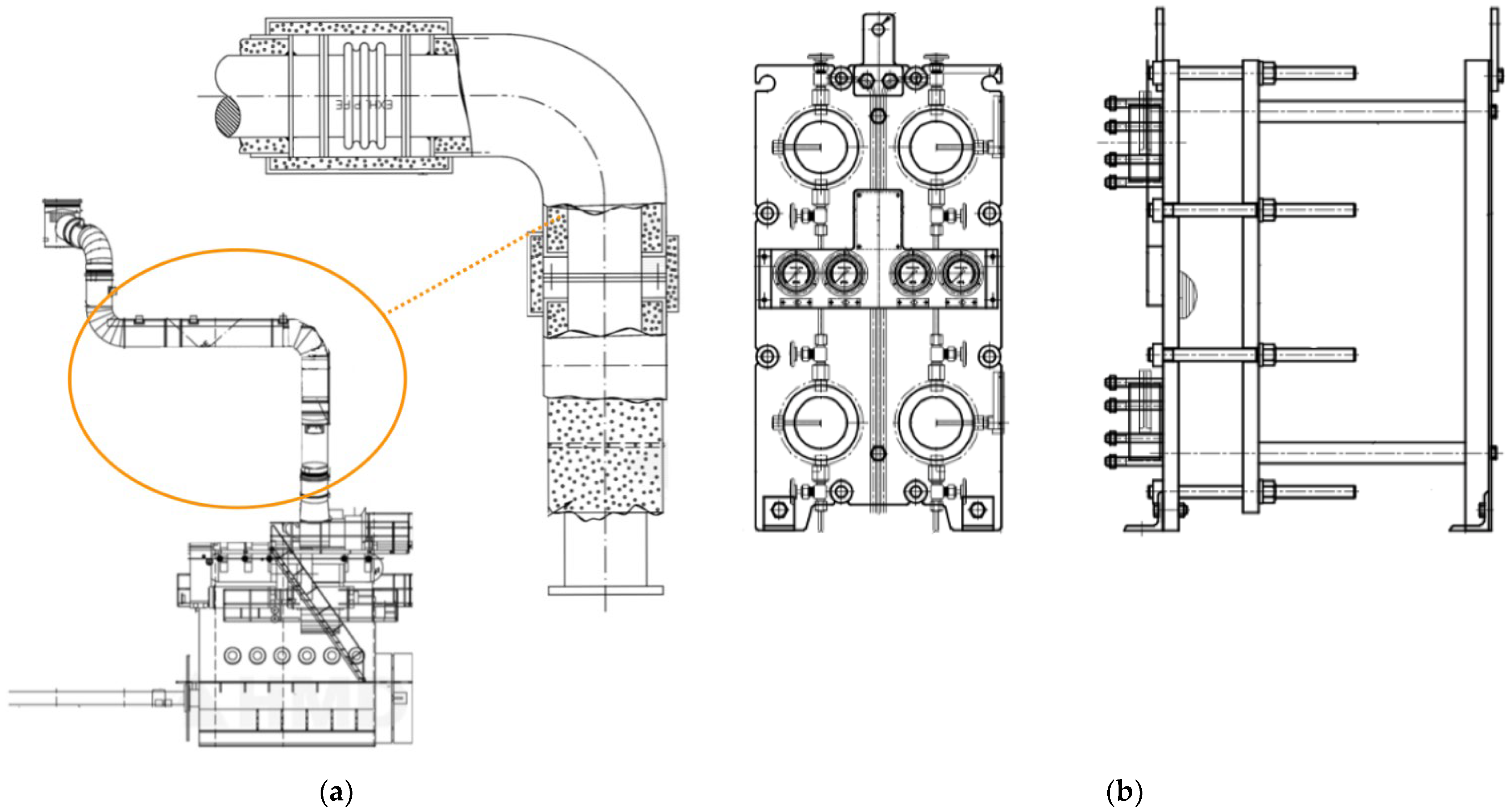
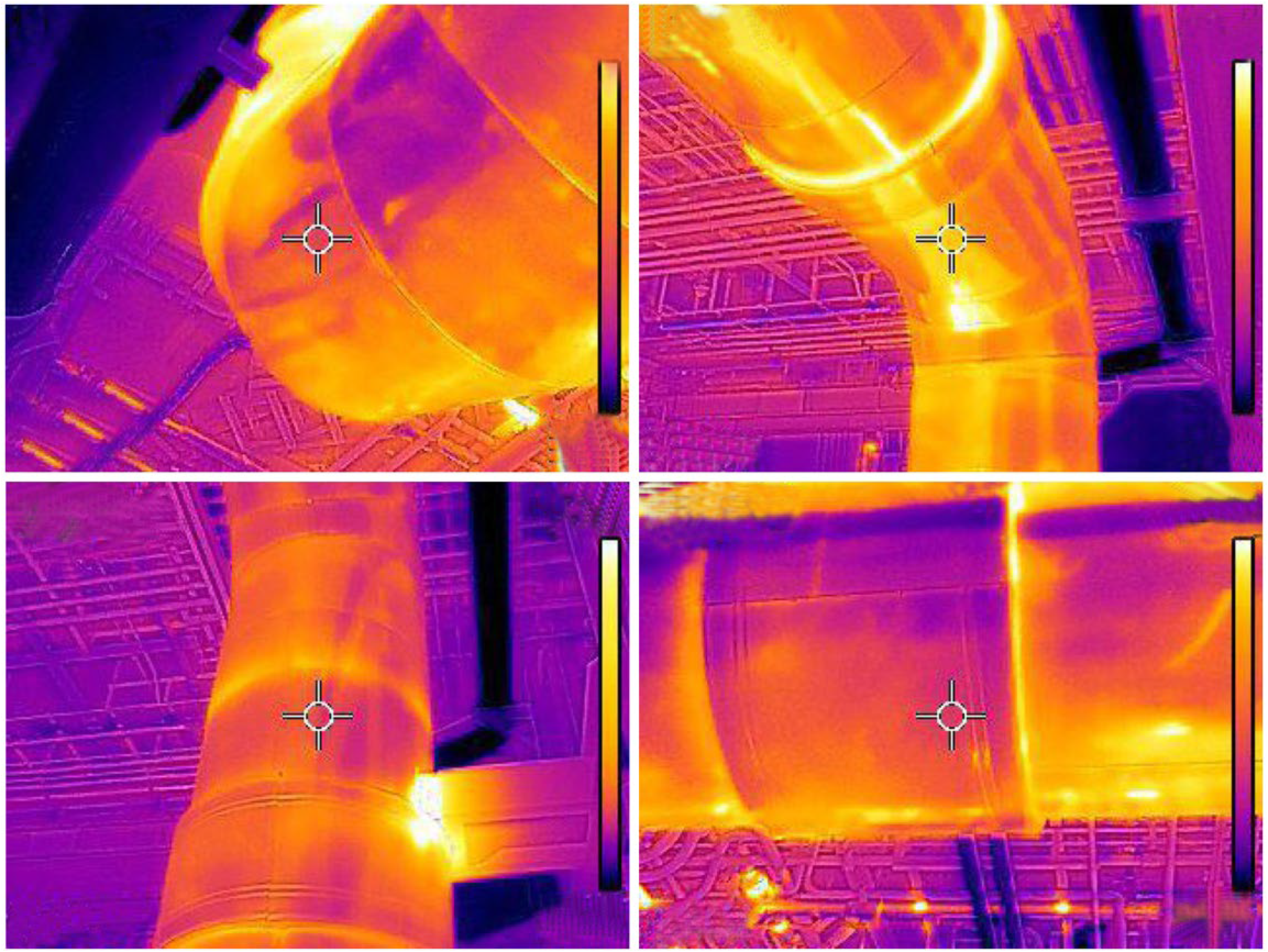
  • Effective zones with high-temperature differences were analyzed. The heatmaps were created using the real measurements of the ship’s main engine exhaust gas outlet line and jacket cooling water heat exchanger;
  • The conditions of thermoelectric generators with high heat resistance were examined in the determined zones to provide optimum results.
Within the scope of the research findings, it can be said that the use of a thermoelectric generator as an extra waste heat recovery system on ships will reduce fuel consumption and contribute to energy efficiency.
The rest of the paper is organized as follows: Thermoelectric materials and working principles are introduced in Section 2. The methodology of the article is provided in Section 3. The case study and results are presented in Section 4, and the conclusion of the study is detailed in Section 5.

2. Working Principles of Thermoelectric Materials

In the marketplace, thermoelectric materials for power generation are available as modules. These devices are usually made of solid-state materials and are composed of multiple layers [43]. Due to their structure, thermoelectric couples are constructed of semiconductor materials (n-type and p-type) connected electrically in a series while thermally connected in parallel. The transfer of electron flow to the section where the temperature is low, with the help of temperature differences, generates electrical energy in thermoelectric generators [44]. To obtain high power from thermoelectric generators, the voltage must be increased, and for this reason, it is necessary to increase the Seebeck coefficient [45]. To generate the Seebeck voltage, each element of the thermoelectric couple must have a monotype charge carrier [41]. The ZT coefficient expresses the suitability of a substance for thermoelectric energy production. The coefficient can be found using Equation (1).
Z T = σ α 2 T κ
where the specified Seebeck coefficient is α, the temperature is T, electrical conductivity is (σ) and thermal conductivity is represented by (κ). The coefficient of efficiency calculation in this system is provided in Equation (2).
η = P Q k
where P is the electrical energy used for the load, and the heat used by the hot side is expressed by Q. Here, η max is found as follows (Equation (3)):
η max = T h T c T h   1 + Z T ̅ 1 1 + Z T ̅ + T c T h
where T h and T c represent the temperatures on the hot and cool sides, respectively. The Carnot efficiency value, which appears in the equation, is generally used when calculating the efficiency of thermoelectric devices. Equation (4) shows the maximum conversion efficiency of a thermoelectric device.
η max = α p α n 2 T ̅ κ p Q p 1 / 2 + κ n Q n 1 / 2 2  
where σ represents the electrical conductivity, T is the mean temperature between the sides (hot-cold), and n and p represent the properties of thermoelectric materials. When Equations (1) and (4) are examined, a high ZT coefficient can increase the Seebeck coefficient. It is expected that such a material has high electrical conductivity and low thermal conductivity. Thermal transport is an important consideration in thermoelectricity. It is formed by phonons and charge carriers, as shown in Equation (5).
κ = κ e + κ l
where ( κ e ) represents charge carriers that allow heat to be transported, and (κl) represents the phonons that continue to move across the grids of the material [25]. The coefficient in Equation (5) increases with electrical conductivity, and it is described as follows (Equation (6)):
κ e = L σ T = n e c μ c LT
where L is the Lorentz number. As the density of the charge carrier increases, the Seebeck coefficient decreases, and it can be determined that the thermal and electrical conductivity increase. Semiconductors are generally used to produce materials with a high thermoelectric coefficient. The carrier concentration of these materials is between 1019 and 1021 cm3 [30]. Recent advances in materials science have also contributed to the development of thermoelectric modules, providing better accessibility and reducing their cost. In this way, more efficient thermoelectric couples could be produced [31].

Estimation of Ship Emission Inventory

Exhaust emissions from ships are evaluated through bottom-up and top-down methods. In the bottom-up method, AIS data describing the operational activities of marine vessels are used, and an inventory is created by estimating emissions. In the other method, the top-down method, emission estimation is performed by taking into account the fuel consumption data of the ship. In this context, the type of fuel used by the ship, cruise, maneuver, port, and anchoring time are examined and calculated separately for each ship. The formula used for the top-down method is provided in Equation (7) [46].
E trip = p ( F C   j , m , p   × E F   i , j , m , p )
where E “voyage” is a movement of a ship for commercial purposes starting from one port of call and ending at the other port and represents the emissions during the voyage (tonnes), FC is fuel consumption (tonnes), EF represents the emission factors determined for fuels (kg/tonne), i indicates emission types such as “NOX, SOX, CO2, PM (Particulate Matter)”, j is the engine type used on the ship (slow speed, medium speed, high speed), m represents the fuel type (VLSFO, HFO, MGO/MDO), and p represents the different voyage (cruise, berth, maneuver) situations. Emission factors have been generated by IMO based on fuel types and data collected in the 2020 Fourth IMO Greenhouse Gas Study. Emission factors are shown in Table 1 [47]. Very Low Sulfur Fuel Oil (VLSFO) is a blended fuel with a certain mixing ratio for the IMO 2020 Global Sulfur Cap regulation. Ref. [48] considers this mixing ratio as approximately 80% MGO and 20% HFO. Emission factors evaluated for VLSFO are evaluated according to percentage.

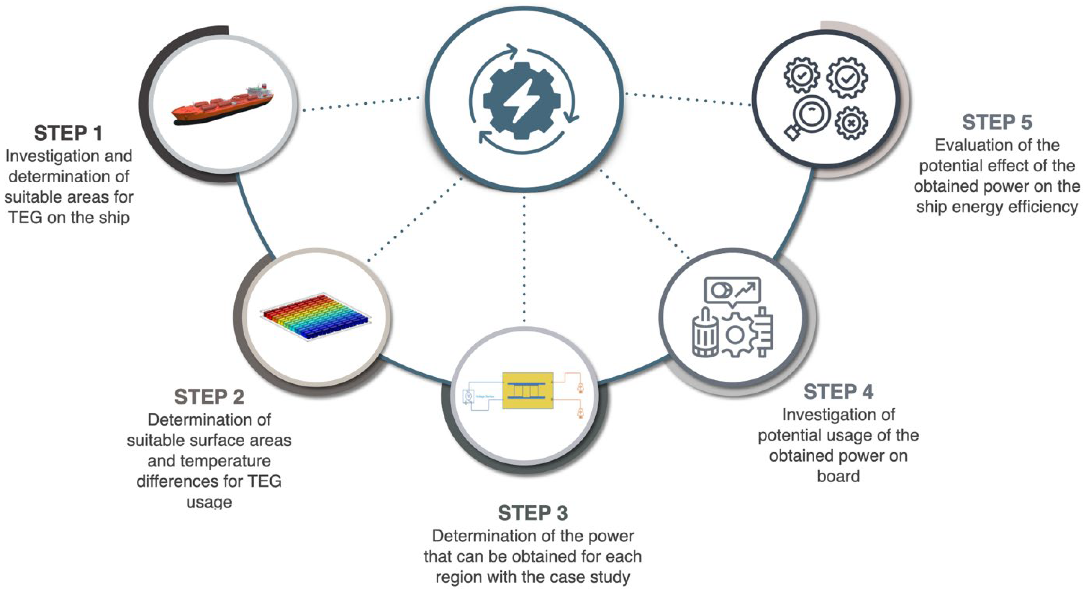
3. Methodology of the Study

Within the scope of the study, an oil/chemical tanker ship was examined, and in this context, the ship’s main engine exhaust gas outlet line and jacket cooling water heat exchanger were analyzed. The characteristics of the vessel investigated are given in Table 2. For the designed thermoelectric generator (TEG) system, a surface area of 43.5 m2 on the main engine (ME) exhaust outlet line surface and 5.0 m2 on the main engine jacket cooling water (JCW) heat exchanger surface was determined by the heat difference regions considered. Average temperatures were taken from these surface areas during a cruise performed in smooth weather conditions. The temperature differences between them and the environments in which they were located were determined. TEGs with properties that can withstand these temperatures were selected as the next step. The methodology followed in the study is outlined in Figure 1.
TEGs with suitable properties were placed on the surfaces and electrical power generation was obtained from the temperature difference based on the Peltier effect. The potential usage areas of the power recovered due to the system were investigated and its effect on energy efficiency was discussed. The TEG design for the main engine exhaust outlet line surface examined in this context is given in Figure 2a, and the design for the jacket cooling water heat exchanger surface is provided in Figure 2b.

4. Case Study and Results

To evaluate the environmental benefits of TEGs, data from the ship’s noon report were analyzed, including data on FO usage, generator loads, and temperature measurements. The data from the ship chosen for the study cover the time period of the voyage, which was between 2020 and 2021, and evaluates the effectiveness of TEGs. The yearly cumulative working hours of the main and auxiliary engines were 5193.66, 1957.22, 2186.33, and 2399.94 h, respectively. Moreover, while examining the noon report data, the average kW value of the A/Es was found to be 450 kW. In addition, Table 3 shows the specific fuel consumptions for generators based on their various loads.
According to MGO and VLSFO pricing, fuel expenses were estimated to be 726 $/MT and 613 $/MT for this time period, respectively [35]. Table 4 shows the overall quantity of fuel utilized by the ship’s main and auxiliary engines, as well as their expenditures.
Equation (6) was used to determine the inventory of emissions released into the atmosphere by the ship, with details represented in Table 5. According to the data, ship emissions in the 2020–2021 period were found as 14,534.24 tons of CO2, 271.83 tons of NOX, 41.26 tons of SOX, 8.81 tons of PM10, and 8.11 tons PM2.
The next stage of this study was to investigate high-temperature zones to install TEG systems aboard the selected ship. The surface areas and temperature differences suitable for TEG application were determined following the analysis process, as well as the surfaces on which the application could be made. The ME exhaust outlet (turbocharger exhaust outlet) line and the ME JCW heat exchanger were chosen as the ideal surfaces. The following are the average values obtained from the ship’s one-year voyage data: engine room average ambient temperature of 33 °C, ME exhaust outlet temperature od 230 °C, JCW heat exchanger hot side inlet-outlet temperatures of 90–78.6 °C, respectively cold side temperatures of 38–54 °C, and a surface temperature of 66.6 °C. The heat maps were examined during the navigation period in the case study’s assigned locations. The net locations where TEGs can produce energy were studied according to the heatmaps. Following that, these heat maps were used to calculate the power produced in the case study. The calculated power was compared to the ship’s generated electrical power. When an adequate surface area and acceptable temperature variations are provided, TEGs can act as efficient waste heat recovery devices. Trip data and equipment manuals were used to gather power statistics for various systems aboard the ship. It turns out that TEGs can meet some of these devices’ power requirements.
When examining the primary engine exhaust gas pipe shown in Figure 2a, it is clear that it has a cylindrical surface. On this surface, there are two layers of protective insulation. The temperature on the exterior surface of the primary engine exhaust gas pipe circuit without insulation was 324 °C. The temperature of the first layer of the heat isolator was measured to be around 230 °C. On the surface of the second layer of insulating material, a temperature of around 50 °C was detected. A thermal camera was used to conduct a technical investigation of the ship’s sections with temperature differences, and some instances are displayed in Figure 3.
When analyzing the drawings of the main engine exhaust gas pipe, an approximate length of 10.715 m on which TEG can be applied to the cylindrical structure can be measured. The diameter of the first insulation layer is 0.5 m. According to a rough calculation, it was determined that 13,286 TEGs can be applied to this surface. When the ME JCW heat exchanger surface, which was inspected as the other TEG application area, was examined, the optimum application area was determined to be approximately 4.5 m2. It was also calculated that 1800 TEGs can be applied to the surface of the ME JCW heat exchanger. The characteristics of the TEG to be used, obtained from the manufacturer, are given in Figure 4a. The heat map of the second surface, which is considered within the scope of the application, is given in Figure 4b.
After analyzing the heat map shown in Figure 4b and the TEG properties, it was determined that the area with approximately 1127 TEGs can generate 4.5 watts of power per TEG. The heat difference map was examined, and it was determined that 553 and 120 TEGs could produce 4.3–4.1 watts of power per TEG device, respectively, in the other heat layers that formed. Considering Figure 2 and Figure 3 and the application surface areas, the potential power for the main engine exhaust gas pipe is approximately 79,720 watts, and the potential power for the ME JCW heat exchanger surface is nearly 7941.4 watts. With the help of TEGs, it was determined that a total of 87,661 watts of power could be recovered in the examined tanker ship. As a result of the analysis, the amount of potential fuel savings that could be realized with the help of TEGs was calculated based on the annual average kW values of the generators. First of all, it was determined that there is a fuel-saving potential of approximately 77.90 tons per year with the help of the power obtained from the TEG system (Figure 2a) when the main engine exhaust gas is active for the cruise condition. When the other TEG system (Figure 2b) was examined, it was determined that its active time per year would be 8765 h, and that the generator fuel consumption value can be reduced by 13.3 tons. When the working hours were examined, it was determined that the fuel-saving values were 25.61 tons of MGO and 65.59 tons of VLSFO. Based on these values, it was found that annual fuel savings values were USD 16,102.62 for MGO and USD 40,206.32 for VLSFO. For the demonstration of the effect of the designed TEG system on the ship’s energy efficiency, the power requirement of the ship’s auxiliary machinery systems provided in Figure 5 were examined.
In light of the findings, the annual fuel consumption data were evaluated and it was determined that the total consumption value of 4553.77 tons could be reduced by approximately 2% to enhance the ship’s energy efficiency.

Cost Analysis of the System

The concept design for integrating the TEG system into the ship’s microgrid is given in Figure 6. It can be seen that the TEG system is divided into three groups and connected to the main switchboard with the help of three inverters. The reason for dividing the system into three groups is to ensure that the inverters operate under optimum voltage and power. The cost of the TEG system, the characteristics of the inverters that connect the system to the ship’s microgrid, and the annual maintenance cost of the overall design are given in Table 6.
In the design phase, TEGs were connected to the inverters in three groups in the series in sets of two hundred in order to provide the input voltage of the inverter. In order to increase the power, TEGs can be connected in parallel to these groups. Thus, the desired power can be supplied to the ship’s electrical microgrid. Including the 15% installation, cables and labour costs, an investment cost of USD 169,439 is required to install the system. The annual maintenance (1%) cost is added to this amount starting from the second year [53]. On the other hand, the system will save approximately USD 56,309 annually. From the second year on, when the maintenance cost is deducted from the savings achieved through the system, the annual savings will be USD 54,835.2. As a result of such a cost analysis, it can be predicted that the system will be able to amortize its cost at the beginning of the fourth year.

5. Conclusions

Recently, energy efficiency in the maritime sector has gained importance due to the increasing energy demand, impacts of climate change, emission regulations and limited sources. Many research and development studies related to increasing efficiency and decreasing emissions have been carried out using solar, wind energy and battery application for maritime microgrids. This study proposed a novel approach of using thermoelectric generators as waste-heat recovery systems on ships, an alternative method for decreasing fuel consumption and emissions. Moreover, the real measurements obtained in the vessel were used to determine heatmaps and emission inventory. On the other hand, a mathematical model description of thermoelectric generator systems was evaluated for the ship.
An analysis was performed utilizing the TEG system in this study to target existing waste-heat recovery in ships and evaluate its contribution to energy efficiency. TEG efficiency was determined by observing the fuel consumption and produced average electrical energy by the generators over the course of a year on the ship. Two zones on the ship where high heat efficiency can be obtained were identified, and heat maps were used to determine areas appropriate for TEG installation. Critical findings for the usage of TEGs on ships were obtained as a result of the research.
Because the heat exchanger used to cool the main engine jacket water is constantly in operation, it generates a continuous source of heat. TEGs can actively create energy throughout their lifetime because of the temperature difference in this location. The main engine exhaust outlet line, through which the exhaust gas passes, is another location that was selected because it is one of the places on the ship with a considerable difference. Electrical energy may be created with the aid of the system built when the ship’s main engine is running, and the power acquired from this region can be used to operate some of the ship’s auxiliary systems. The combined output of the two systems is around 88 kW, which is particularly useful during the ship’s voyage. With the produced power, it was found that many of the ship’s systems can be fed separately or in combination, depending on the situation. During the generation of electric power from the designed TEG system, DC converters may be necessary to store and transmit the energy to the ship microgrid. As a result, throughout the installation procedure, TEGs must be optimized for the ship’s electrical grid. During application, this circumstance causes several issues (determining the placement of dc converters, optimizing electrical circuits, etc.). Despite these drawbacks, the installation of TEG systems on the ship has the following major benefits:
  • It was determined that installing TEG systems on the ship used in the case study would result in a 2% gain in energy efficiency within a year;
  • The obtained energy efficiency would help in the reduction of exhaust emissions as well as fuel savings, therefore contributing to the marine industry’s long-term sustainability and green future goals;
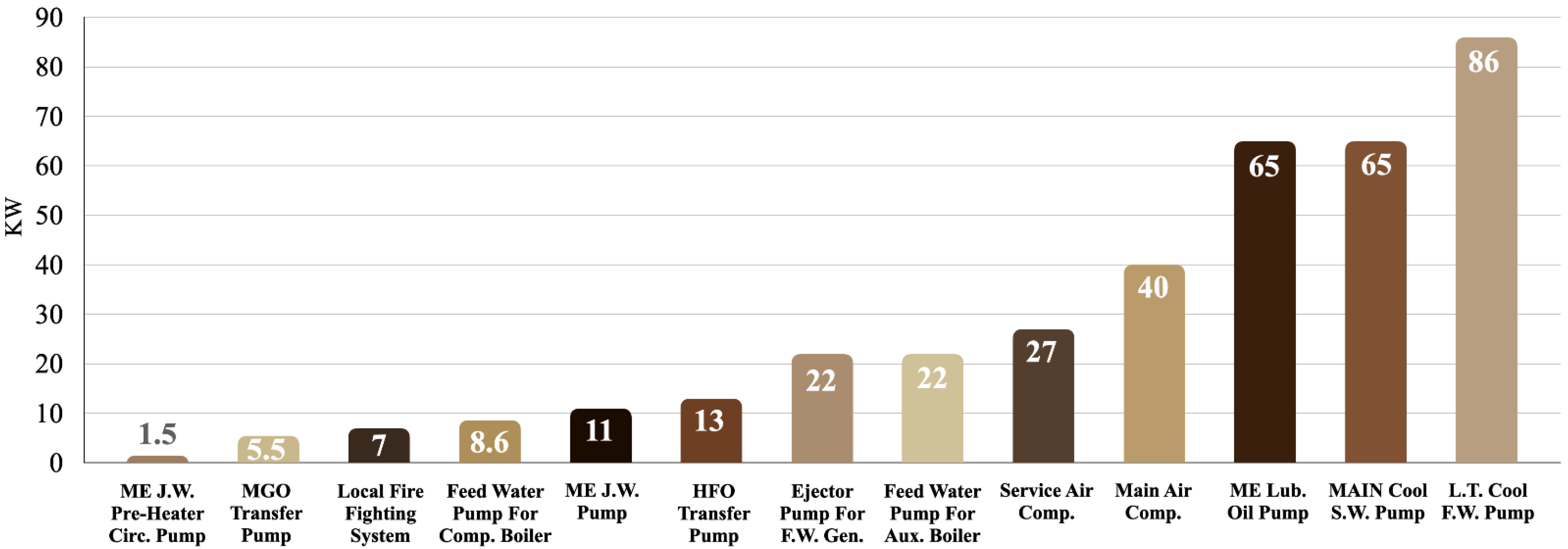
  • TEG systems can feed the main cooling seawater pump for the ship cooling system, and the main and service air compressor responsible for supplying the necessary air for the systems onboard. By increasing the ship’s energy efficiency while cruising, fuel savings can be achieved;
  • Local Fire Prevention System pumps could be kept available, independent of the ship’s energy grid, through the TEG system designed for the ME JCW heat. The simple structure and prolonged life of TEGs can make them easy to utilize throughout the ship’s commercial life.
This research focuses on the usage of waste heat recovery TEG systems in the ship’s main engine exhaust gas outlet line and jacket cooling water heat exchanger. The proposed approach can be applied to other part of ships and various ship types such as containers and cruises. Moreover, the integration of other energy-saving technologies such as wind and solar into the proposed method would increase energy efficiency. In further studies, the creation of hybrid systems, the submission of a feasibility study, and cost analysis will invite the interest of maritime industry stakeholders.

Author Contributions

T.U.: Conceptualization, Methodology, Software, Validation, Formal analysis, Writing—original draft, E.E.: Conceptualization, Methodology, Validation, Writing—review and editing, Writing—original draft, Y.A.: Supervision, Investigation, Writing—review and editing, Writing—original draft, Y.Y.: Validation, Visualization, Writing—review and editing, Y.T.: Writing—review and editing, C.-L.S.: Supervision, Writing—review and editing, J.M.G.: Supervision, Writing—review and editing. All authors have read and agreed to the published version of the manuscript.

Funding

This work was supported by The Scientific and Technological Research Council of Turkey BIDEB 2214-A International Doctoral Research Fellowship Programme reference number: 1059B142100334. The work of C.-L.S. was funded by the Ministry of Science and Technology of Taiwan under Grant MOST 107-2221-E-992-073-MY3.

Institutional Review Board Statement

Not applicable.

Informed Consent Statement

Not applicable.

Data Availability Statement

Not applicable.

Acknowledgments

The authors would like to acknowledge the support from the Scientific and Technological Research Council of Turkey BIDEB 2214-A International Doctoral Research Fellowship. The work of C.-L.S. was funded by the Ministry of Science and Technology of Taiwan under Grant MOST 107-2221-E-992-073-MY3.

Conflicts of Interest

The authors declare no conflict of interest.

References

  1. Lindstad, E.; Lagemann, B.; Rialland, A.; Gamlem, G.M.; Valland, A. Reduction of Maritime GHG Emissions and the Potential Role of E-Fuels. Transp. Res. Part D Transp. Environ. 2021, 101, 103075. [Google Scholar] [CrossRef]
  2. EIA Energy Information Administration. Choice Rev. Online 2019, 44, 44–3624. [CrossRef]
  3. Nuchturee, C.; Li, T.; Xia, H. Energy Efficiency of Integrated Electric Propulsion for Ships—A Review. Renew. Sustain. Energy Rev. 2020, 134, 110145. [Google Scholar] [CrossRef]
  4. MEPC. Annex 19: Resolution; MEPC, 2011; Volume 203, pp. 1–17. Available online: https://wwwcdn.imo.org/localresources/en/OurWork/Environment/Documents/Technical%20and%20Operational%20Measures/Resolution%20MEPC.203%2862%29.pdf (accessed on 9 May 2022).
  5. Ampah, J.D.; Yusuf, A.A.; Afrane, S.; Jin, C.; Liu, H. Reviewing Two Decades of Cleaner Alternative Marine Fuels: Towards IMO’s Decarbonization of the Maritime Transport Sector. J. Clean. Prod. 2021, 320, 128871. [Google Scholar] [CrossRef]
  6. IMO. MEPC.1/Circ.684; IMO: London, UK, 2009. [Google Scholar]
  7. IMO. Energy Efficiency Measures; IMO: London, UK, 2015; pp. 1–5. [Google Scholar]
  8. Rehmatulla, N.; Smith, T. Barriers to Energy Efficiency in Shipping: A Triangulated Approach to Investigate the Principal Agent Problem. Energy Policy 2015, 84, 44–57. [Google Scholar] [CrossRef] [Green Version]
  9. ABS. Ship Energy Efficiency Measures Advisory; ABS, 2014; p. 74. Available online: https://ww2.eagle.org/content/dam/eagle/advisories-and-debriefs/ABS_Energy_Efficiency_Advisory.pdf (accessed on 9 May 2022).
  10. Mallouppas, G.; Yfantis, E.A. Decarbonization in Shipping Industry: A Review of Research, Technology Development, and Innovation Proposals. J. Mar. Sci. Eng. 2021, 9, 415. [Google Scholar] [CrossRef]
  11. Bouman, E.A.; Lindstad, E.; Rialland, A.I.; Strømman, A.H. State-of-the-Art Technologies, Measures, and Potential for Reducing GHG Emissions from Shipping—A Review. Transp. Res. Part D Transp. Environ. 2017, 52, 408–421. [Google Scholar] [CrossRef]
  12. Olaniyi, E.O.; Atari, S.; Prause, G. Maritime Energy Contracting for Clean Shipping. Transp. Telecommun. 2018, 19, 31–44. [Google Scholar] [CrossRef] [Green Version]
  13. Karatsoli, M.; Nathanail, E. A Thorough Review of Big Data Sources and Sets Used in Transportation Research; Springer: Cham, Switzerland, 2018; Volume 36, pp. 540–550. ISBN 9783319744537. [Google Scholar]
  14. Diesel, M.A.N. Turbo, Thermo Efficiency System. 2014. Available online: https://mandieselturbo.com/docs/default-source/shopwaredocuments/efficiency-of-man-b-w-two-stroke-engines.pdf (accessed on 10 May 2022).
  15. Shu, G.; Liang, Y.; Wei, H.; Tian, H.; Zhao, J.; Liu, L. A Review of Waste Heat Recovery on Two-Stroke IC Engine Aboard Ships. Renew. Sustain. Energy Rev. 2013, 19, 385–401. [Google Scholar] [CrossRef]
  16. Lion, S.; Vlaskos, I.; Taccani, R. A Review of Emissions Reduction Technologies for Low and Medium Speed Marine Diesel Engines and Their Potential for Waste Heat Recovery. Energy Convers. Manag. 2020, 207, 112553. [Google Scholar] [CrossRef]
  17. Singh, D.V.; Pedersen, E. A Review of Waste Heat Recovery Technologies for Maritime Applications. Energy Convers. Manag. 2016, 111, 315–328. [Google Scholar] [CrossRef]
  18. Guo, X.; Zhang, H.; Wang, J.; Zhao, J.; Wang, F.; Miao, H.; Yuan, J.; Hou, S. A New Hybrid System Composed of High-Temperature Proton Exchange Fuel Cell and Two-Stage Thermoelectric Generator with Thomson Effect: Energy and Exergy Analyses. Energy 2020, 195, 117000. [Google Scholar] [CrossRef]
  19. Magwili, G.V.; Bulaong, M.L.D.; Macose, A.M.P.; Rodriguez, P.S.B. Thermos Design and Assembly for Conversion of Heat to Electrical Energy Based from the Principle of Seebeck Effect Using Thermoelectric Generator and Temperature Difference of Liquids. AIP Conf. Proc. 2018, 2045, 020057. [Google Scholar] [CrossRef]
  20. Solanki, S.S.; Chavan, A.B.; Tharwal, O.N.; Ghadi, T.M.; Sawant, S.P.; Bondre, S.S. Design and Implementation of Thermoelectric Energy Harvesting System with Thermoelectric Generator for Automobiles Battery Charging. In Proceedings of the International Conference on Inventive Communication and Computational Technologies (ICICCT), Coimbatore, India, 20–21 April 2018; pp. 131–134. [Google Scholar] [CrossRef]
  21. Wiriyasart, S.; Naphon, P. Thermal to Electrical Closed-Loop Thermoelectric Generator with Compact Heat Sink Modules. Int. J. Heat Mass Transf. 2021, 164, 120562. [Google Scholar] [CrossRef]
  22. Wang, J.; Cao, P.; Li, X.; Song, X.; Zhao, C.; Zhu, L. Experimental Study on the Influence of Peltier Effect on the Output Performance of Thermoelectric Generator and Deviation of Maximum Power Point. Energy Convers. Manag. 2019, 200, 112074. [Google Scholar] [CrossRef]
  23. Reverter, F. A Tutorial on Thermal Sensors in the 200th Anniversary of the Seebeck Effect. IEEE Sens. J. 2021, 21, 22122–22132. [Google Scholar] [CrossRef]
  24. Jouhara, H.; Żabnieńska-Góra, A.; Khordehgah, N.; Doraghi, Q.; Ahmad, L.; Norman, L.; Axcell, B.; Wrobel, L.; Dai, S. Thermoelectric Generator (TEG) Technologies and Applications. Int. J. Thermofluids 2021, 9, 100063. [Google Scholar] [CrossRef]
  25. Yusuf, A.; Bayhan, N.; Ibrahim, A.A.; Tiryaki, H.; Ballikaya, S. Geometric Optimization of Thermoelectric Generator Using Genetic Algorithm Considering Contact Resistance and Thomson Effect. Int. J. Energy Res. 2021, 45, 9382–9395. [Google Scholar] [CrossRef]
  26. Vostrikov, S.; Somov, A.; Gotovtsev, P.; Magno, M. Comprehensive Modelling Framework for a Low Temperature Gradient Thermoelectric Generator. Energy Convers. Manag. 2021, 247, 114721. [Google Scholar] [CrossRef]
  27. Li, X.; Wang, J.; Meng, Q.; Yu, D.; Huang, Z. The Influence of Peltier Effect on the Exergy of Thermoelectric Cooler-Thermoelectric Generator System and Performance Improvement of System. SSRN Electron. J. 2021, 3918962. [Google Scholar] [CrossRef]
  28. Zaferani, S.H.; Jafarian, M.; Vashaee, D.; Ghomashchi, R. Thermal Management Systems and Waste Heat Recycling by Thermoelectric Generators—An Overview. Energies 2021, 14, 5646. [Google Scholar] [CrossRef]
  29. Zoui, M.A.; Bentouba, S.; Stocholm, J.G.; Bourouis, M. A Review on Thermoelectric Generators: Progress and Applications. Energies 2020, 13, 3606. [Google Scholar] [CrossRef]
  30. Aridi, R.; Faraj, J.; Ali, S.; Lemenand, T.; Khaled, M. Thermoelectric Power Generators: State-of-the-Art, Heat Recovery Method, and Challenges. Electricity 2021, 2, 359–386. [Google Scholar] [CrossRef]
  31. Araiz, M.; Casi, Á.; Catalán, L.; Aranguren, P.; Astrain, D. Thermoelectric Generator with Passive Biphasic Thermosyphon Heat Exchanger for Waste Heat Recovery: Design and Experimentation. Energies 2021, 14, 5815. [Google Scholar] [CrossRef]
  32. Jia, X.; Fan, S.; Zhang, Z.; Wang, H. Performance Assessment of Thermoelectric Generators with Application on Aerodynamic Heat Recovery. Micromachines 2021, 12, 1399. [Google Scholar] [CrossRef]
  33. Albatati, F.; Attar, A. Analytical and Experimental Study of Thermoelectric Generator (Teg) System for Automotive Exhaust Waste Heat Recovery. Energies 2021, 14, 204. [Google Scholar] [CrossRef]
  34. Von Lukowicz, M.; Schmiel, T.; Rosenfeld, M.; Heisig, J.; Tajmar, M. Characterisation of TEGs Under Extreme Environments and Integration Efforts Onto Satellites. J. Electron. Mater. 2015, 44, 362–370. [Google Scholar] [CrossRef]
  35. Von Lukowicz, M.; Abbe, E.; Schmiel, T.; Tajmar, M. Thermoelectric Generators on Satellites—An Approach for Waste Heat Recovery in Space. Energies 2016, 9, 541. [Google Scholar] [CrossRef]
  36. Moreno, R.J.; Pollman, A.; Grbovic, D. Harvesting Waste Thermal Energy from Military Systems. Am. Soc. Mech. Eng. Power Div. Power 2018, 2, V002T12A012. [Google Scholar] [CrossRef]
  37. Dai, D.; Zhou, Y.; Liu, J. Liquid Metal Based Thermoelectric Generation System for Waste Heat Recovery. Renew. Energy 2011, 36, 3530–3536. [Google Scholar] [CrossRef]
  38. Meng, F.; Chen, L.; Xie, Z.; Ge, Y. Thermoelectric Generator with Air-Cooling Heat Recovery Device from Wastewater. Therm. Sci. Eng. Prog. 2017, 4, 106–112. [Google Scholar] [CrossRef]
  39. Chen, L.G.; Meng, F.K.; Sun, F.R. Thermodynamic Analyses and Optimization for Thermoelectric Devices: The State of the Arts. Sci. Chin. Technol. Sci. 2016, 59, 442–455. [Google Scholar] [CrossRef]
  40. Qiu, K.; Hayden, A.C.S. Development of a Thermoelectric Self-Powered Residential Heating System. J. Power Sources 2008, 180, 884–889. [Google Scholar] [CrossRef]
  41. Fernández-Yáñez, P.; Romero, V.; Armas, O.; Cerretti, G. Thermal Management of Thermoelectric Generators for Waste Energy Recovery. Appl. Therm. Eng. 2021, 196, 117291. [Google Scholar] [CrossRef]
  42. Ezgi, C.; Özbalta, N.; Girgin, I. Thermohydraulic and Thermoeconomic Performance of a Marine Heat Exchanger on a Naval Surface Ship. Appl. Therm. Eng. 2014, 64, 413–421. [Google Scholar] [CrossRef]
  43. Sifi, I.; Kaid, N.; Ameur, H.; Inc, M.; Baleanu, D.; Menni, Y.; Lorenzini, G. Comparison between the Thermoelectric Properties of New Materials: The Alloy of Iron, Vanadium, Tungsten, and Aluminum (Fe2V0.8W0.2Al) against an Oxide Such as NaCO2O4. Optik 2021, 247, 168035. [Google Scholar] [CrossRef]
  44. Tan, Q.; Chen, G.; Sun, Y.; Duan, B.; Li, G.; Zhai, P. Performance of Annular Thermoelectric Couples by Simultaneously Considering Interface Layers and Boundary Conditions. Appl. Therm. Eng. 2020, 174, 115301. [Google Scholar] [CrossRef]
  45. Aravind, B.; Hiranandani, K.; Kumar, S. Development of an Ultra-High Capacity Hydrocarbon Fuel Based Micro Thermoelectric Power Generator. Energy 2020, 206, 118099. [Google Scholar] [CrossRef]
  46. EMEP/EEA EMEP/EEA. Air Pollutant Emission Inventory Guidebook 2019. J. Chem. Inf. Model. 2019, 53, 1689–1699. [Google Scholar]
  47. IMO. Fourth IMO GHG Study 2020; International Maritime Organization: London, UK, 2020. [Google Scholar]
  48. Pavlenko, N.; Comer, B.; Zhou, Y.; Clark, N.; Rutherford, D. The Climate Implications of Using LNG as a Marine Fuel. ICCT Work. Pap. 2020-02. 2020. Available online: https://Theicct.Org/Sites/Default/Files/Publications/Climate_implications_LNG_marinefuel_01282020.Pdf (accessed on 12 May 2022).
  49. Marlow Industries. Technical Data Sheet for TG12-8 Single-Stage Thermoelectric Generator; Marlow Industries Europ: Weiterstadt, Germany, 2021; pp. 1–2. [Google Scholar]
  50. TG12-6-01L-II-VI Marlow Stock Available. The Distributor Micro-Semiconductor.Com Offer the Best Price with New Original Products. Available online: https://www.micro-semiconductor.com/products/Luminary-Micro-Texas-Instruments/SN74AHC125N (accessed on 12 May 2022).
  51. Inverter, Solar Inverter, Home Power Inverter. Available online: https://www.inverter.com/ (accessed on 12 May 2022).
  52. Väisänen, J.; Kosonen, A.; Ahola, J.; Sallinen, T.; Hannula, T. Optimal Sizing Ratio of a Solar PV Inverter for Minimizing the Levelized Cost of Electricity in Finnish Irradiation Conditions. Sol. Energy 2019, 185, 350–362. [Google Scholar] [CrossRef]
  53. Celik, A.N.T.; Muneer, P.C. Optimal Sizing and Life Cycle Assessment of Residential Photovoltaic Energy Systems with Battery Storage. Prog. Photovolt. Res. Appl. 2015, 20, 6–11. [Google Scholar] [CrossRef]
Figure 1. Methodology of the study.
Energies 15 04248 g001
Figure 2. (a) Surface area for the TEG system designed on the ME exhaust outlet line; (b) Surface for the TEG system designed on the ME JCW heat exchanger.
Energies 15 04248 g002
Figure 3. Thermal inspection of areas for the TEG applications.
Energies 15 04248 g003
Figure 4. (a) The characteristics of the TEG [36]; (b) Heat map of ME JCW heat exchanger (°C).
Energies 15 04248 g004
Figure 5. Power needs for the ship’s auxiliary machineries.
Energies 15 04248 g005
Figure 6. The conceptual design for integrating the TEG system into the ship’s microgrid.
Energies 15 04248 g006
Table 1. The emission factors.
Fuel Type N O X
(kg/tonne)
S O X
(kg/tonne)
PM10
(kg/tonne)
PM2.5
(kg/tonne)
C O 2
(kg/tonne)
HFO75.9050.837.556.943.114
MGO56.711.370.900.833.206
Table 2. Particulars of the ship.
Specifications
Type of the shipTanker
Built year2017
Length O. A. (m)183.0
Breadth (m)32.20
Deadweight (Tonnes)49,900
Main engine typeSlow speed
Main engine power (kW)8502
Aux. engine power (kW)900 × 3
Exh. Gas quantity (kg/h)58,900
Exh. Gas Avg. Temp. (°C)324
Table 3. SFOC values for aux. engines.
LOAD (%)25507585100
SFOC207193189189192
Table 4. Fuel consumption and costs between 2020–2021.
Fuel TypeME
(tonne/yr)
AE
(tonne/yr)
ME
($/yr)
AE
($/yr)
MGO841.59171.71$610,994$124,660
VLSFO3120.11420.37$1,912,626$257,685
Table 5. Exhaust Emission Inventory for ship.
EmissionME
(kg/tonne)
AE
(kg/tonne)
Total
(kg/tonne)
CO212,643.791890.4614,534.25
NOX236.6435.19271.83
SOX36.294.9741.26
PM107.721.098.81
PM2.57.101.018.11
Table 6. System installation and maintenance cost (USD).
Item NameQuantityUnit CostTotal CostUnit Specifications
TEG [49]15,0868.911134,431[50]
Inverter [51]34312.4712,938Input Voltage = 820 VDC, Output Voltage = 440 VAC, Output Power = 30 kW
Installation [52]1-22,100-
Maintenance [53]Per year1473.8/yr1473.8/yr-
Publisher’s Note: MDPI stays neutral with regard to jurisdictional claims in published maps and institutional affiliations.

