Article

Model Predictive Control for PMSM Based on Discrete Space Vector Modulation with RLS Parameter Identification

School of Automation, Hangzhou Dianzi University, Hangzhou 310018, China
*
Author to whom correspondence should be addressed.
Energies 2022, 15(11), 4041; https://doi.org/10.3390/en15114041
Submission received: 2 April 2022 / Revised: 21 May 2022 / Accepted: 30 May 2022 / Published: 31 May 2022

Abstract

:
Model Predictive Control (MPC) based on Discrete Space Vector Modulation (DSVM) has the advantages of simple mathematical model and fast dynamic response. It is widely used in permanent magnet synchronous motor (PMSM). Additionally, the control performance of DSVM-MPC is influenced by the accuracy of motor parameters and the select speed of optimal voltage vector. In order to identify motor parameters accurately, model predictive control for PMSM based on discrete space vector modulation with recursive least squares (RLS) parameter identification is proposed in this paper. Additionally, a method to preselect candidate voltage vectors is proposed to select the optimal voltage vector more quickly. The simulation model of RLS-DSVM-MPC is established to simulate the influence of different parameters on PMSM performance. The simulation results show that model predictive control for PMSM based on discrete space vector modulation with RLS parameter identification has a better control performance than that of without RLS parameter identification.

1. Introduction

Permanent magnet synchronous motor (PMSM) has the advantages of simple structure, high power density and wide speed regulation range [1]. It is widely used in industrial robots, new energy vehicles, aerospace, and other application fields, and it is of great significance to improve the control performance of PMSM [2].
Field oriented control (FOC) and direct torque control (DTC) are control methods widely used in PMSM. FOC can realize accurate control with little speed and torque ripple, but it has slow torque response because of the PI controllers [3]. Reference [4] proposes an indirect FOC method for six-phase induction motor, in which the pulse width modulation signals controls two sets of three-phase voltage source inverters, respectively. DTC has fast dynamic response, but it has disadvantages of high torque ripple and current harmonics, and its switching frequency is not constant. Reference [5] proved that the electromagnetic torque in PMSM is proportional to the angle between the stator and rotor flux linkage. In [6], space vector modulation (SVM) is applied to DTC, and through the output duty cycle of SVM, the switching frequency was able to be fixed.
In addition to FOC and DTC, model predictive control (MPC) is widely used in power converters and motor control systems, for that it has the advantages of simple structure, fast dynamic response, and accurate control in steady state [7,8]. MPC can be divided into continuous control set (CCS-MPC) and finite control set (FCS-MPC) according to the type of optimization problem. CCS-MPC calculates the desired voltage vector, and then outputs the corresponding duty cycle through the modulator, thus it has a fixed switching frequency [9]. The commonly used CCS-MPC methods are generalized predictive control (GPC) and explicit model predictive control (EMPC) [10,11]. GPC is mainly used to solves linear and unconstrained problems, while EMPC mainly solves nonlinear and constrained problems. FCS-MPC only uses the voltage vectors that actually exist in the inverter, and it does not require modulator adjustment or duty cycle calculation, so it has fast dynamic response speed and uncertain switching frequency. FCS-MPC can be divided into optimal switching vector (OSV-MPC) [12] and optimal switching sequence (OSS-MPC) [13]. OSV-MPC is currently the most widely used MPC method for power electronics applications. It uses a limited number of voltage vectors as the control set, which reduces the application difficulty of MPC. Meanwhile, OSV-MPC output only one switching sequence in a switching cycle, this led to the increased current and torque ripple. OSS-MPC takes the possible switching sequences in a switching cycle as a control set, and then uses time as an additional constraint to select the optimal switching sequence, so OSS-MPC can act like a modulator.
In recent years, FCS-MPC has been developed and successfully applied in a variety of power converters. Reference [14] proposes a general FCS model predictive torque control (MPTC) method for power converter and driver, which can be controlled easily and does not require additional modulation techniques or internal cascaded control loops. In [15], a multi-step prediction MPTC method is proposed, which can achieve prediction over a range of 150 time steps by using extrapolation and boundary methods, and the discrete-time controller of the drive system derived from physical equations is able to reduce the switching frequency by 50%. Reference [16] compares FOC with MPTC for induction motors, certified that MPTC has better control performance under transient conditions.
For the problem that traditional MPC applies only one voltage vector in switching cycle, researchers proposed an algorithm based on multi-voltage vector synthesis. Reference [17] takes the torque and flux errors as constraints, optimizes the switching sequence and duty cycle by minimizing the torque and flux linkage errors, and finally reduces the switching losses. With the development of MPC, discrete space vector modulation (DSVM) is used to increase the number of candidate voltage vectors in MPC, which can further improve the control performance of motor[18]. Different from the traditional MPC that only considers the effective voltage vector when switching, the DSVM-MPC method presynthesizes a certain number of virtual voltage vectors in one switching cycle. The optimal voltage vector that minimizes the error of constraints such as current, torque, or flux linkage is selected by the value function, and the switching state corresponding to the optimal voltage vector is applied to the three-phase inverter to achieve high-performance control of PMSM. Reference [19] proposed a DSVM-DTC method based on fuzzy logic, which divides the switching cycle into three equal parts, and uses three effective voltage vectors in each switching cycle to synthesize a new virtual voltage vector. A DSVM-MPC method with constant switching frequency and low sampling frequency is proposed in [20], where real voltage vectors are used together with newly synthesized virtual voltage vectors. In [21], a model predictive torque control method with extended control set is proposed, which can further increase the number of candidate voltage vectors and reduces torque pulsation.
However, more candidate voltage vectors bring greater computational burden and longer time to select the optimal voltage vector. To solve these problem, researchers have made a lot of efforts. Reference [22] proposes a method based on sliding mode preselection, which can reduce the number of candidate voltage vectors from 19 to 10, and can save the execution time of the entire control algorithm. Reference [23] uses the deadbeat technique to obtain the expected voltage vector, and then selects the candidate voltage vector which is closest to it. A robust deadbeat DSVM-MPC method is proposed in [24], which has high-quality current waveform and fixed switching frequency. Reference [25] proposes twenty modulated voltage space vectors with fixed duty cycle, and a preselection method is designed to filter out unreasonable voltage vectors, which can reduce the computational burden caused by the increased number of voltage space vectors. Reference [26] uses the DTC switching table to reduce the number of candidate voltage vectors, and prove that it has similar control performance to conventional MPTC. This paper also proposes a method for preselecting the candidate voltage vectors, which can reduce the number of candidate voltage vectors from 38 to 13.
DSVM can improve the control performance of MPC for PMSM, furthermore, improving the accuracy of PMSM parameters can also make contribution to it. There are mainly two kinds of parameter estimation to improve the accuracy of PMSM parameters, one offline parameter estimation and the other online [27]. Offline estimation is widely used in the machine and controller design. Reference [28] proposes an offline identification method and accurately predicts the machine parameters. However, the offline estimation cannot identify the variation of parameters in real time, especially for some parameters which are greatly influenced by operating conditions. Meanwhile, the online estimation method is primarily concerned with real-time [7]. In [29], the recursive least squares (RLS) estimator is used to estimate the incremental stator inductances online, rather than using a conventional offline look-up table. In this paper, an online parameter identification method using RLS is proposed, by which accurate PMSM parameters can be identified and updated for DSVM-MPC in real time.
The remainder of this paper is organized as following four sections. The principles of RLS-DSVM-MPC are provided in Section 2. The implementation of RLS-DSVM-MPC is given in Section 3. The results analysis from model simulation validation is provided in Section 4. Additionally, some conclusions are drawn in Section 5.

2. The Principles of RLS-DSVM-MPC

2.1. The Mathematical Model of PMSM

The PMSM voltage equation in the d-q axis is shown in Equation (1):
v d v q = R s ω e L q ω e L d R s i d i q + L d 0 0 L q p i d i q + ω e 0 ψ p m
where v d and v q are the voltage of d and q axes, respectively; L d and L q are the inductance of d and q axes, respectively; i d and i q are the stator current of d and q axes, respectively; R s is the stator resistance; ω e is the electrical angular velocity of the rotor; ψ p m is the permanent magnet flux linkage of rotor; and p represents the difference d / d t .

2.2. The Principles of MPCC

Model predictive current control (MPCC) predicts current according to the discrete mathematical model of PMSM, and uses the constraint relationship between the expected value and the predicted value to select the optimal voltage vector to reduce current harmonics and torque pulsation. In this paper, i d and i q are selected as the states to be predicted.
The PMSM discrete current equation in the dq axis [24] is shown in Equation (2):
i ^ s ( k + 1 ) = A i s ( k ) + B u s ( k ) + C
where
A = a 11 a 12 a 21 a 22 = 1 R s T s / L d L q T s ω e ( k ) / L d L d T s ω e ( k ) / L q 1 R s T s / L q B = b 11 0 0 b 22 = T s / L d 0 0 T s / L q C = 0 c p = 0 ψ p m T s ω e ( k ) / L q
i ^ s ( k + 1 ) represents the current of stator at moment k + 1 ; i s ( k ) = i d ( k ) i q ( k ) T and u s ( k ) = u d ( k ) u q ( k ) T represent the current and voltage of d and q axes at moment k , respectively; T s represents the sample time.
In the control system, there exists a delay of 2 T s in current sampling and the inverter’s conversion, and the error between the expected and actual current is used to define the cost function. The cost function is expressed as
J ( V n ) = i d ref i ^ d ( k + 2 ) 2 + λ i q ref i ^ q ( k + 2 ) 2
V opt = arg min J ( V n )
where i d ref and i q ref represent the expected current of d and q axes, respectively; λ is defined as the weighting coefficient; V n ( n = 1 , , n total ) represents the voltage vector; V opt represents the optimal voltage vector; i ^ d ( k + 2 ) and i ^ q ( k + 2 ) can be derived from Equation (2).

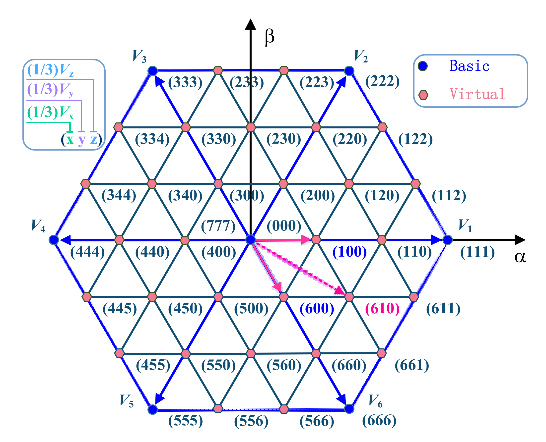
2.3. The Principles of DSVM

DSVM divides each sampling period into N segments, and uses eight basic voltage vectors to synthesize a certain number of virtual voltage vectors in each sampling period to expand the number of candidate voltage vectors. The basic voltage vectors and virtual voltage vectors are expressed as Equations (5) and (6), and the number of all the voltage vectors is expressed as Equation (7):
V b = 2 3 V dc ( S 1 + S 3 e i 2 π / 3 + S 5 e i 2 π / 3 )
v v i r = j = 1 , , N t j V j , t j = T s / N
n t o t a l = 3 N 2 + 3 N + 2
where V b { V 0 , , V 7 } represents the basic voltage vectors; S 1 , S 3 , and S 5 represent the switching signals of converter; v v i r represents the virtual voltage vectors, t j represents the work time of basic voltage vectors. n t o t a l represents the number of all the voltage vectors.
Reference [18] proposes that when the sampling period is divided into three equal parts (N = 3), the discrete space vector modulation method can significantly reduce current harmonics and torque ripple, and there are 38 voltage vectors in total (6 effective voltage vectors, 2 zero-voltage vectors, and 30 virtual voltage vectors). The distribution of each voltage vector is shown in Figure 1.
As is shown in Figure 1, ( 1 / 3 ) V b ( b = 0 , 1 , 2 , , 7 ) is the unit to synthetic virtual voltage vectors, and all voltage vectors are numbered by the value of b (the zero-voltage vector is recorded as 0). For example, if the number of the virtual voltage vector to be synthesized is (610), then the virtual voltage vector will be synthesized by the basic voltage vector V 6 , V 1 , and V 0 .
DSVM increases the number of candidate voltage vectors, but too many candidate voltage vectors make it difficult to select the optimal voltage vector from the 38 candidate voltage vectors quickly. To solve this problem, this paper proposes a preselection method based on effective voltage vector. As is shown in Figure 2, all the candidate voltage vectors are divided into six groups according to the position of every effective voltage vector, and the members of every groups are listed in Table 1. When the preselection method works, the effective voltage vectors are used to quickly determine which group the optimal voltage vector is in, and then the optimal voltage vector will be selected from the group. Though this method, the number of candidate voltage vectors when select the optimal voltage vector can be reduced from 38 to 13, which greatly release the computational burden.

2.4. Parameter Identification Using RLS

The PMSM discrete current equation in the d–q axis can also be expressed as Equation (8):
Y = Θ X
where
X = [ i d ( k 1 ) , i q ( k 1 ) , u d ( k 1 ) , u q ( k 1 ) , 1 ] T Y = i d ( k ) , i q ( k ) T Θ = A , Β , C = a 11 a 12 b 11 0 0 a 21 a 22 0 b 22 c p
In order to identify the parameter matrix Θ online, a recursive least square (RLS) method is used [2], which can be expressed as
Θ ^ ( k ) = Θ ^ ( k 1 ) + ( Y Θ ^ ( k 1 ) X ) X T P ( k )
P ( k ) = ( 1 / ζ ) P ( k 1 ) P ( k 1 ) X ( ζ + X T P ( k 1 ) X ) 1 X T P ( k 1 )
where ζ is the forgetting factor, and it represents the weight of the past data in the identification. P ( k ) represents the covariance matrix at moment k .

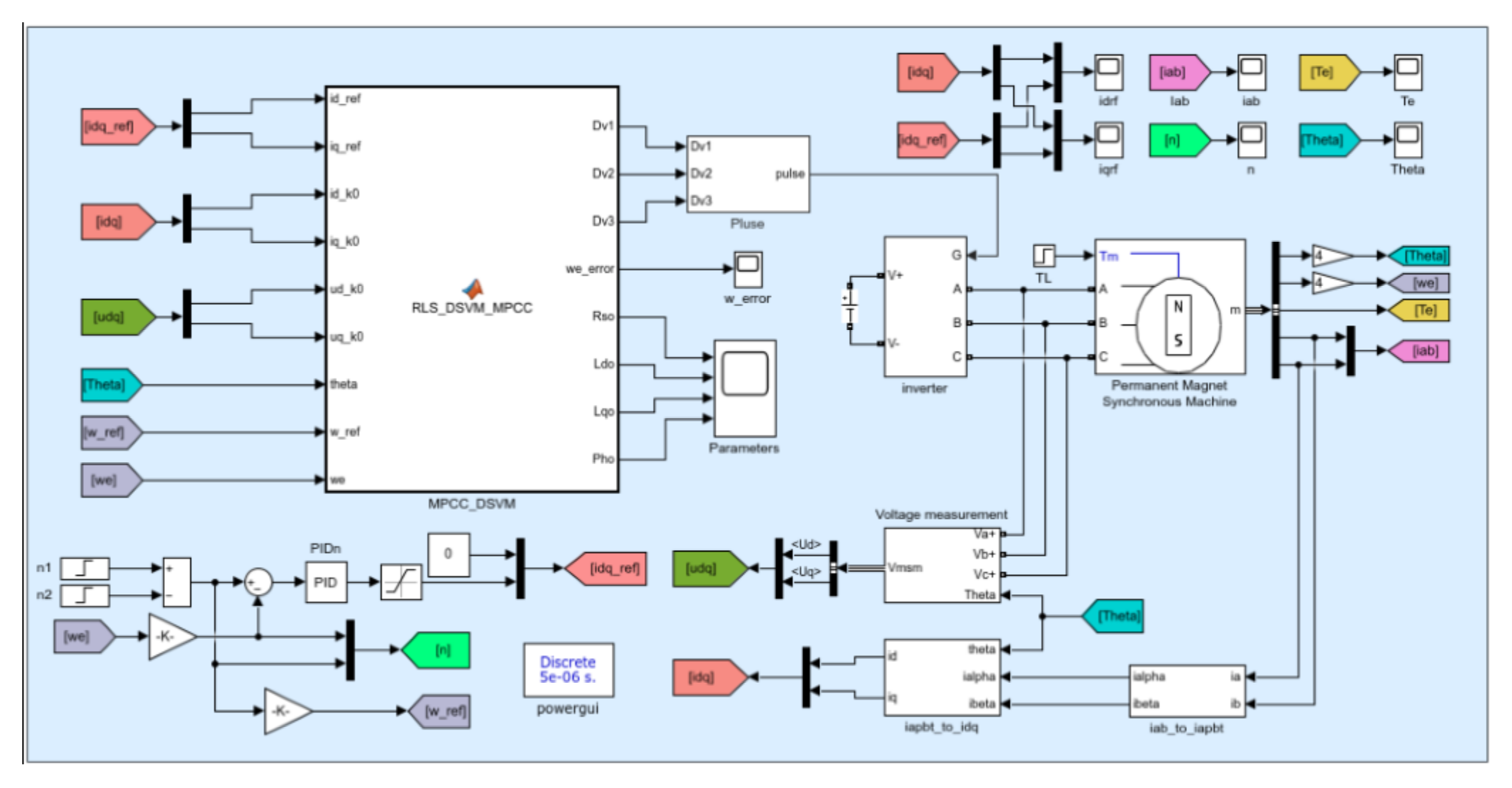
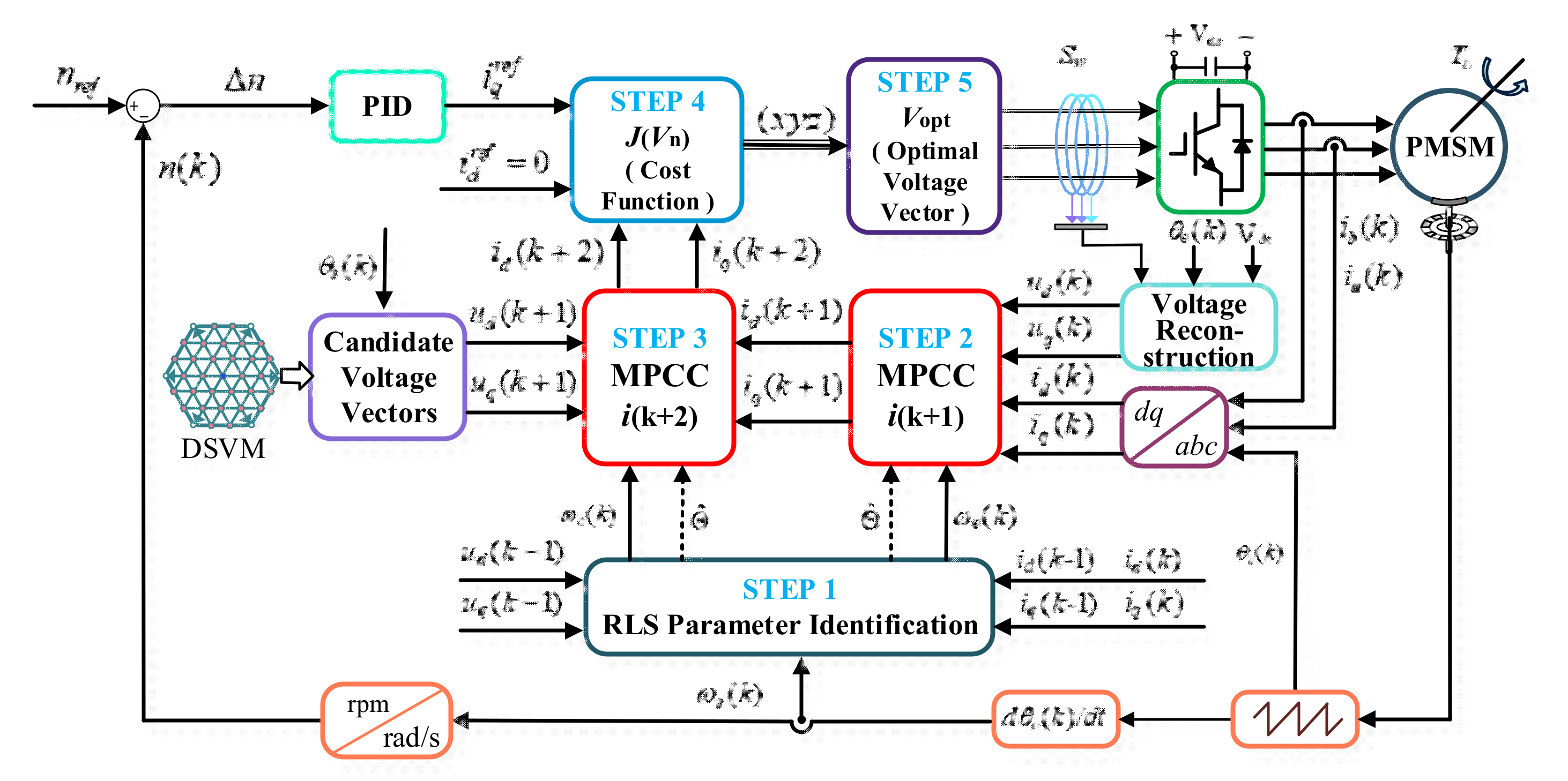
3. The Implementation of RLS-DSVM-MPC

The control structure of RLS-DSVM-MPC is shown in Figure 3, where i d = 0. The control structure includes modules, such as feedback measurement, coordinate transformation, PID regulation, RLS parameter identification, current prediction along with optimal voltage vector selection.
The workflow includes the following five steps.
Step 1: When PMSM works in steady state, then the parameter matrix Θ ^ can be derived from Equations (9) and (10) with i d ( k 1 ) , i q ( k 1 ) , u d ( k 1 ) , and u q ( k 1 ) . This step is realized in RLS parameter identification module.
Step 2: i d ( k + 1 ) and i q ( k + 1 ) can be predicted with i d ( k ) , i q ( k ) , u d ( k ) , u q ( k ) , and Θ ^ .
Step 3: i d ( k + 2 ) and i q ( k + 2 ) can be predicted with i d ( k + 1 ) , i q ( k + 1 ) , and candidate voltage vectors. Additionally, the candidate voltage vectors were synthesized in DSVM. For every candidate voltage vector, we can obtain a set of i d ( k + 2 ) and i q ( k + 2 ) , respectively. Steps 2 and 3 are achieved in current prediction module.
Step 4: Though Equation (3), the cost function J ( V n ) can be computed with i d ( k + 2 ) , i q ( k + 2 ) , i d r e f , and i q r e f .
Step 5: The optimal voltage vector V opt can be derived from Equation (4). Then, the switching state of V opt was applied on the three-phase inverter. Steps 4 and 5 are achieved in optimal voltage vector selection module.

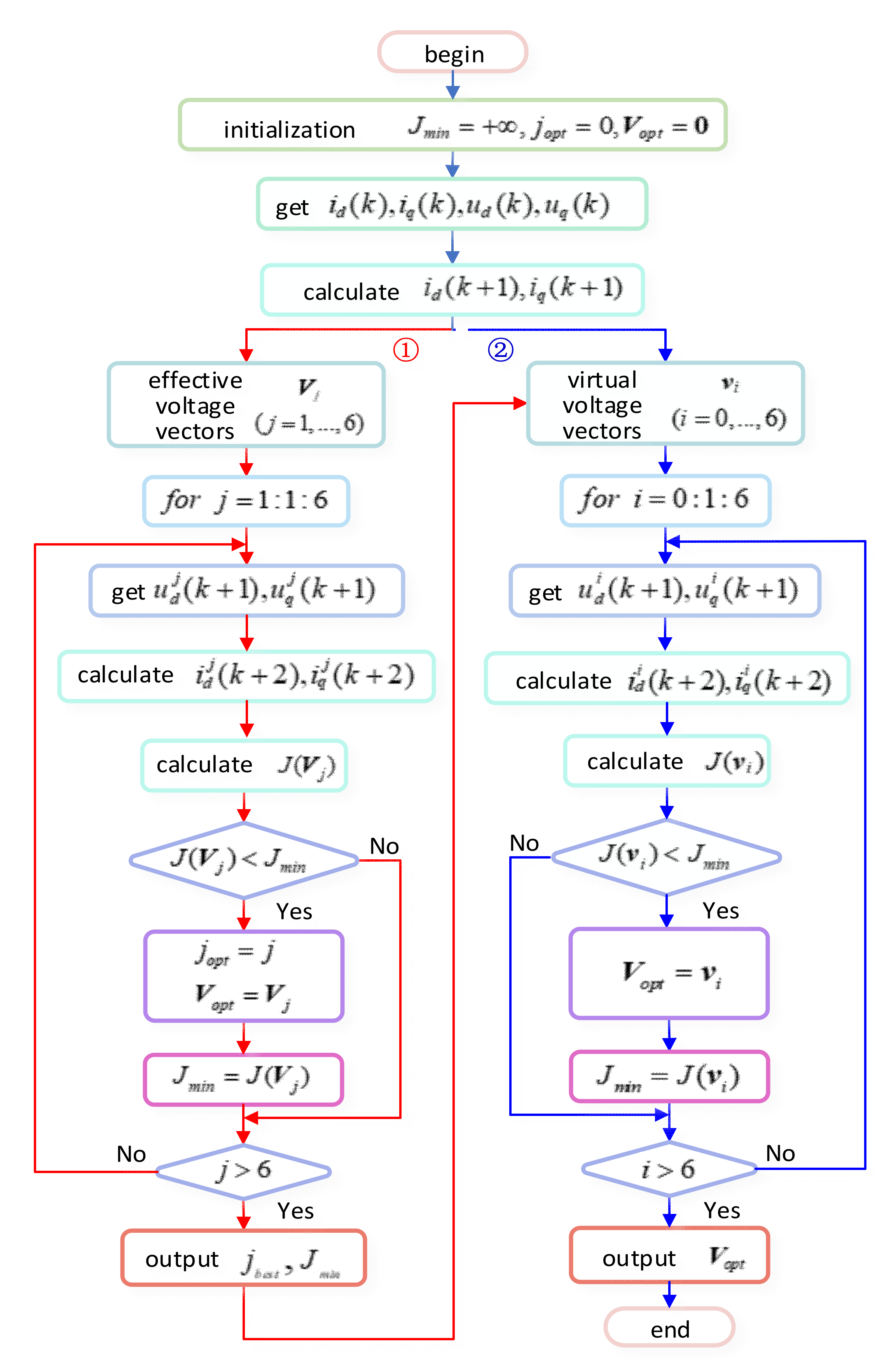
3.1. The Implementation of DSVM-MPCC Module

The procedure to select the optimal voltage vector is shown in Figure 4. In the first step, the effective voltage vectors are used to quickly determine which group the optimal voltage vector is in. Additionally, in step 2, the optimal voltage vector will be selected from the group. Though this method, the number of candidate voltage vectors when select the optimal voltage vector can be reduced from 38 to 13.

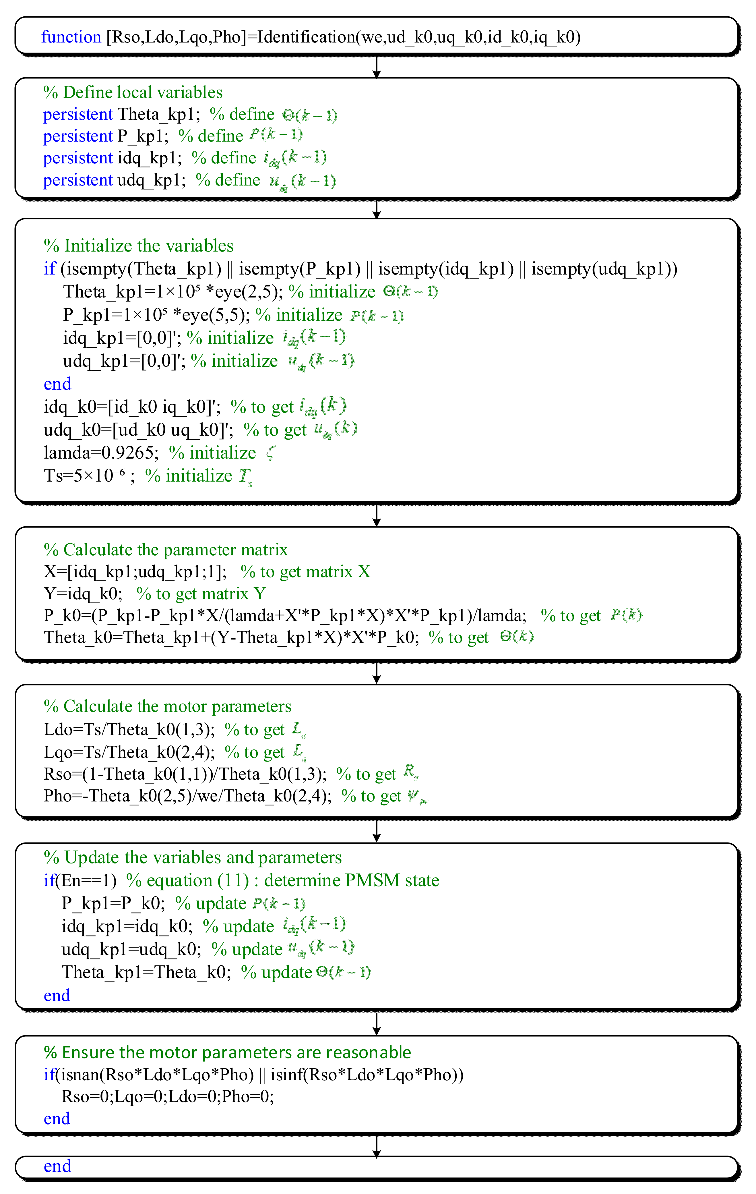
3.2. The Realization of RLS Parameter Identification

RLS parameter identification module is achieved by the function which is shown in Figure 5. In step 1, the variables are defined in the identification function; additionally, in step 2, the variables are initialized to the certain value; step 3, the parameter matrix can be derived from Equations (8)–(10); then, in step 4, the motor parameters can be calculated by the parameter matrix in step 3, referring to matrix A , B , and C ; Step 5, the variables are reinitialized by the formal value, and the function is ready to run for the next time.

3.3. The Update Conditions of RLS Parameter Identification

In this paper, the difference between actual and normal velocity is used to determine whether the PMSM has reached a steady state:
E n = 1 , ω e r e f ω e ω e r e f × 100 % υ 0 , ω e r e f ω e ω e r e f × 100 % > υ
where E n   = 1 means PMSM works in steady state, E n = 0 means PMSM works in dynamic state; ω e r e f represents the normal velocity; ω e represents the velocity; υ represents the threshold to determine the state of PMSM.
When E n   = 1, the RLS parameter identification module can update itself using the newly identified parameters. When E n   = 0, the velocity and load of PMSM change all the time, the module will not update.

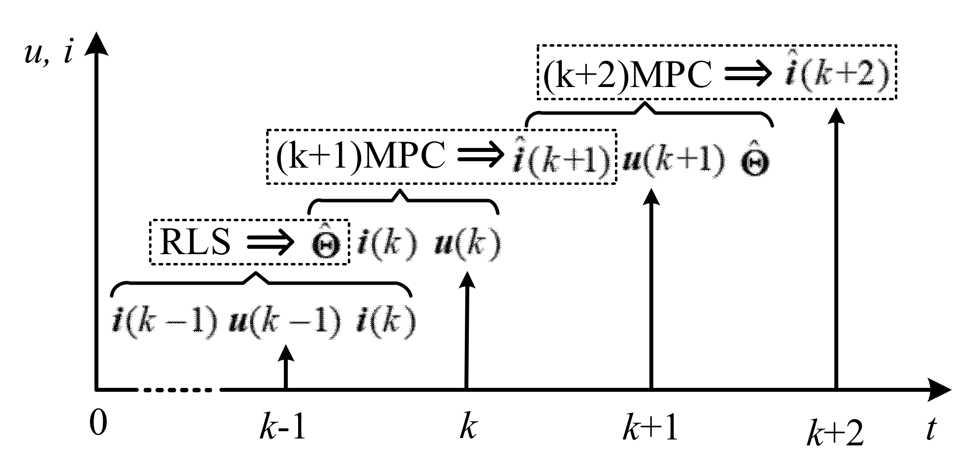
3.4. The Time Sequence of RLS Parameter Identification and MPC

The time sequence of RLS parameter identification and current prediction is shown in Figure 6. First, the parameter matrix Θ ^ was derived with i d ( k 1 ) , i q ( k 1 ) , u d ( k 1 ) , and u q ( k 1 ) . Second, i d ( k + 1 ) and i q ( k + 1 ) were predicted with i d ( k ) , i q ( k ) , u d ( k ) , u q ( k ) , and Θ ^ . Third, i d ( k + 2 ) and i q ( k + 2 ) were predicted with i d ( k + 1 ) , i q ( k + 1 ) , and candidate voltage vectors.

4. Results and Analysis of Simulation

According to the control structure of RLS-DSVM-MPC, the simulation model was built with Matlab/Simulink, and it is shown in Figure 7. The parameters of PMSM are shown in Table 2. The PID parameters are given in Table 3. The sample time T s = 5 × 10 6   s , the weighting coefficient λ = 1 , the RLS forgetting factor ζ = 0.9265 , the threshold υ = 0.02 , and the switching frequency of inverter was set to 20 kHz.
To evaluate the accuracy of the identified parameters, the average parameter error P a e r and the maximum parameter error P m e r were proposed and defined as Equations (12) and (13):
P a e r = 1 N P r e f i = 1 N ( P r e f P ^ i ) × 100 %
P m e r = max | P r e f P | P r e f × 100 %
where P represents R s , L d , L q and ψ p m ; P r e f represents the normal value of the parameters; and P ^ represents the estimated value of the parameter.

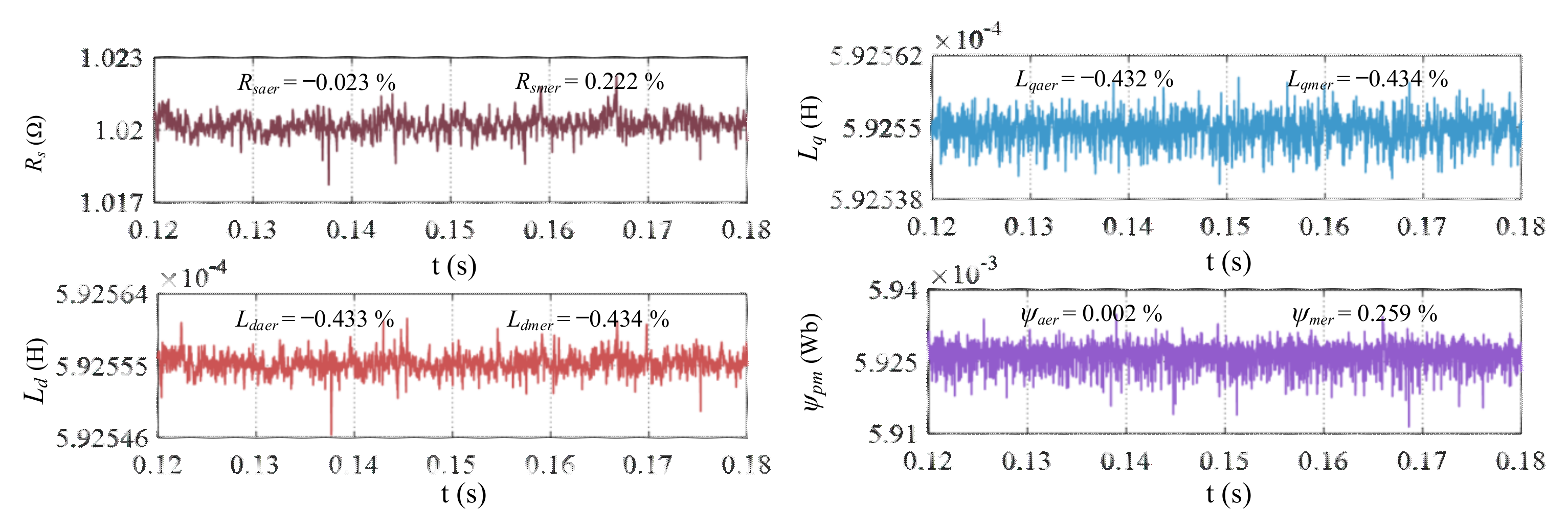
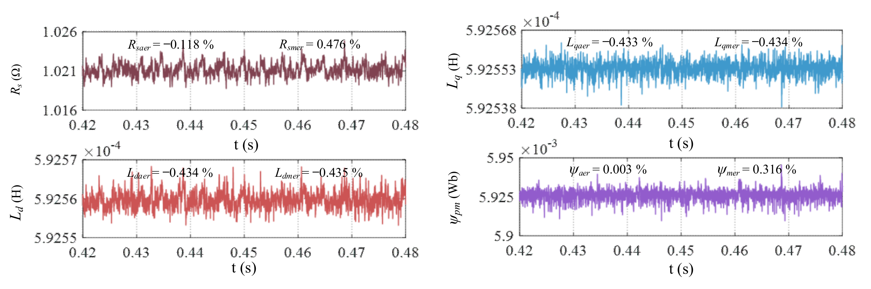
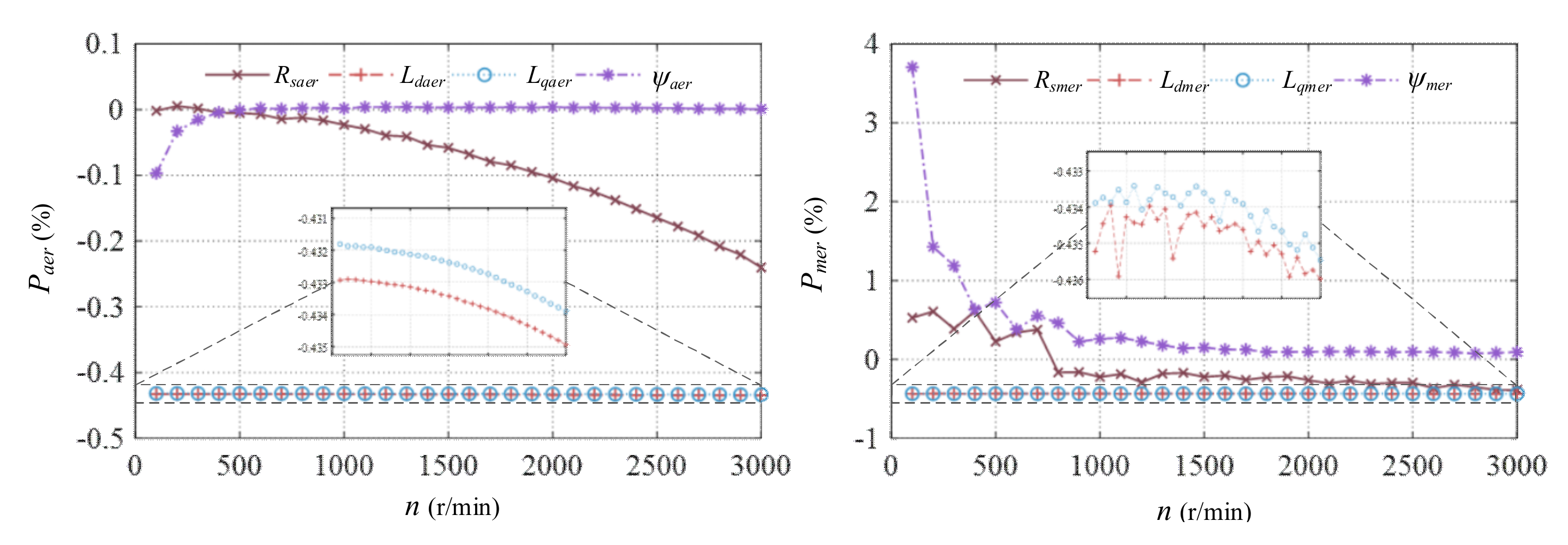
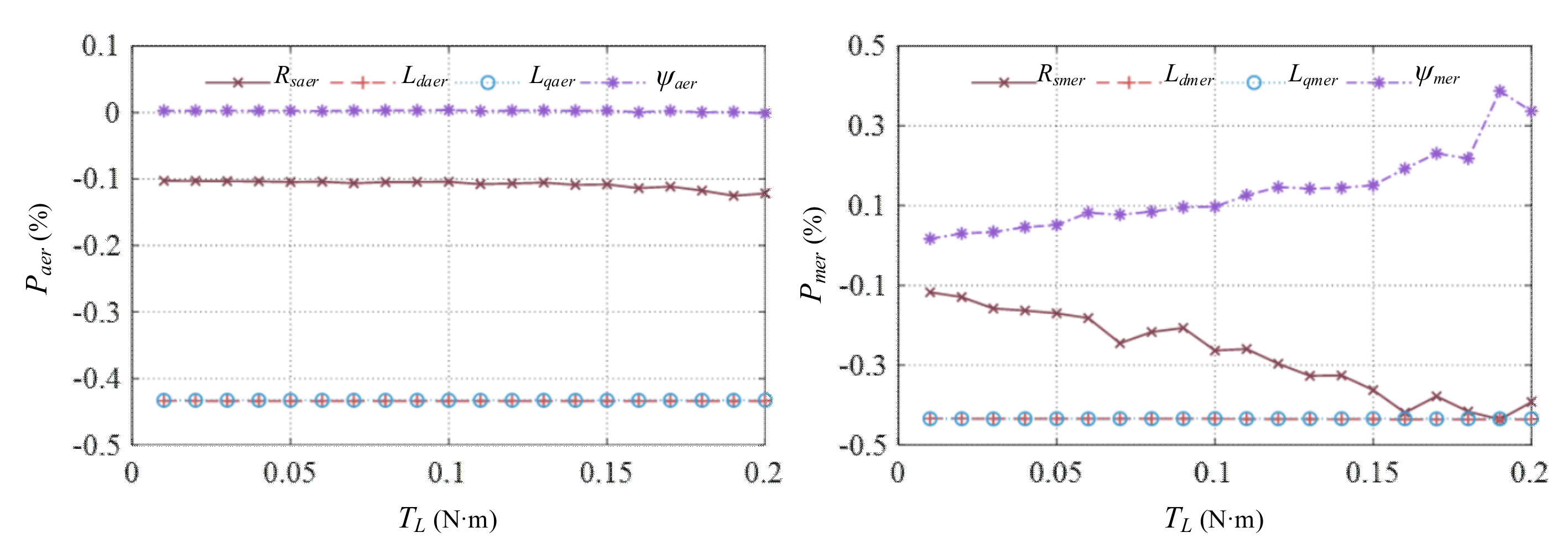
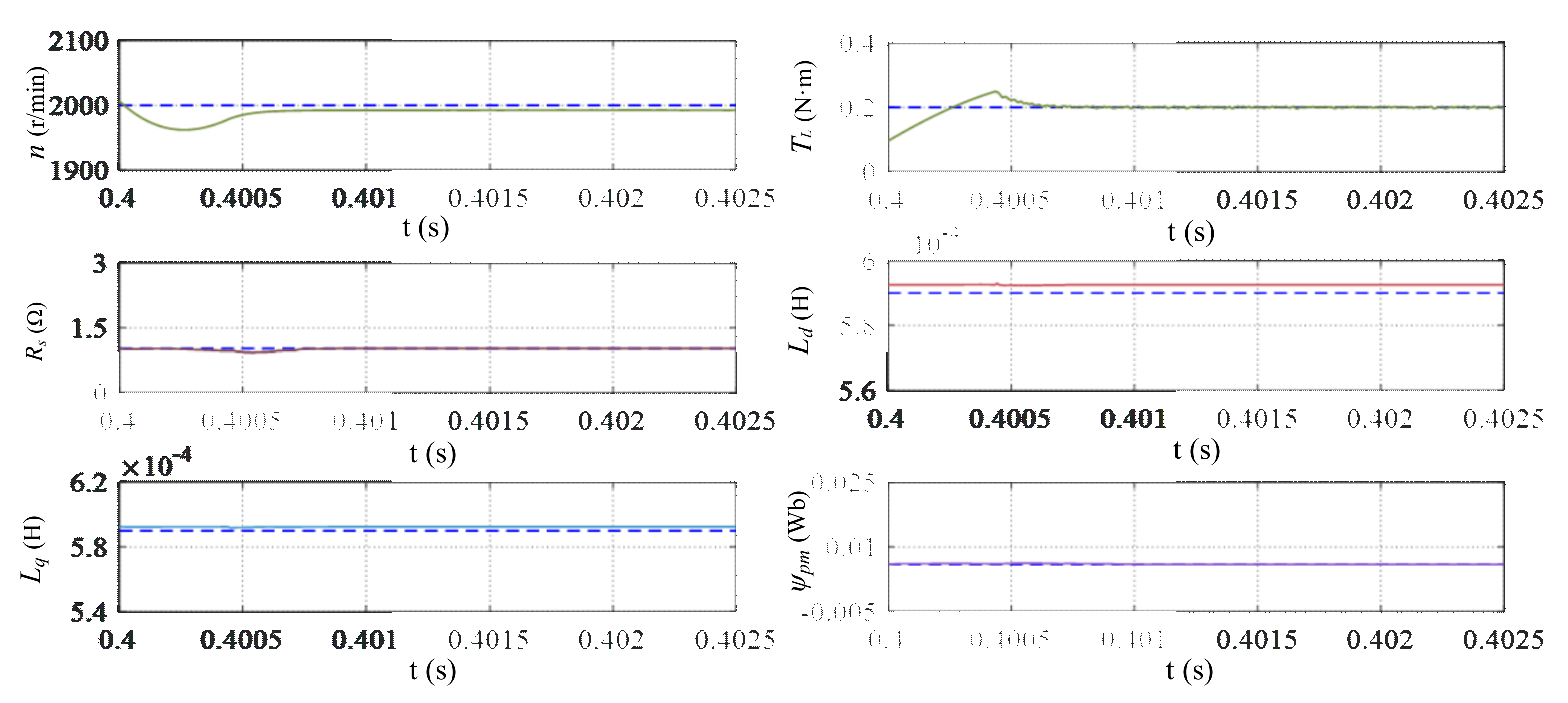
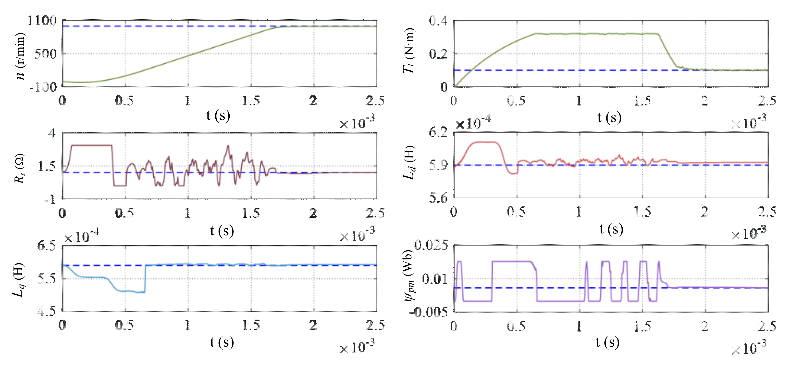
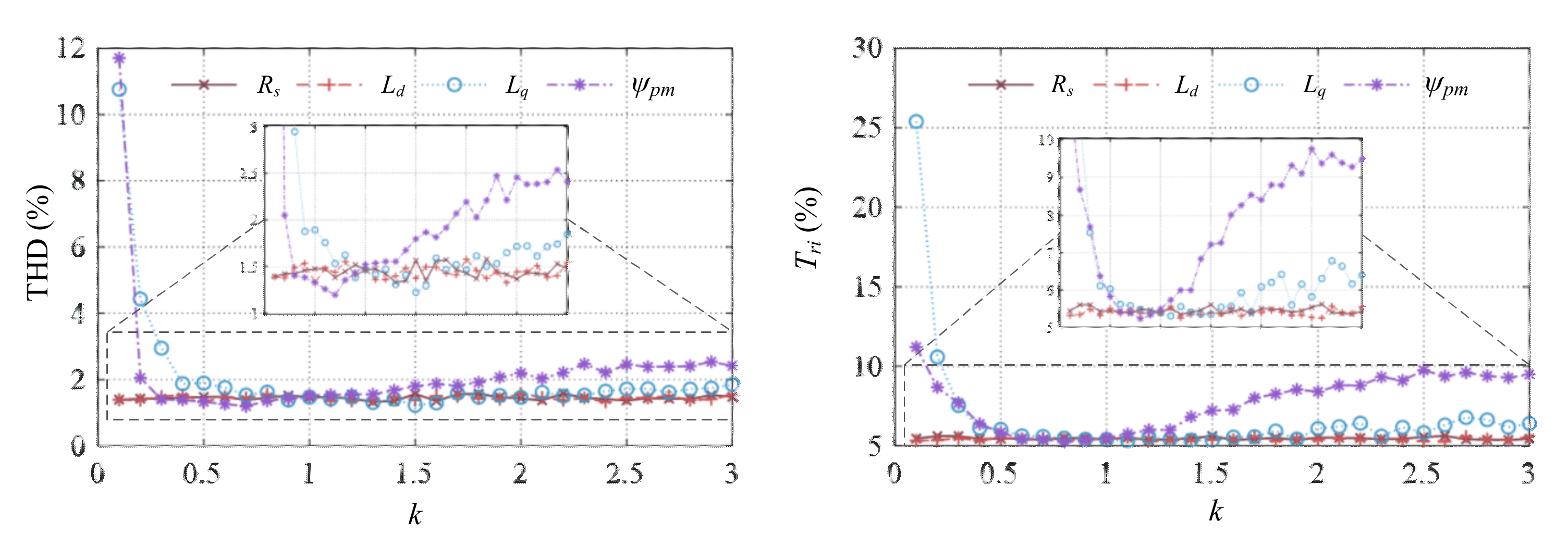
4.1. Static Accuracy of RLS-DSVM-MPC

Figure 8 and Figure 9 show results of parameter identification in the PMSM. Figure 8 shows results while the velocity n = 1000   rpm and the load T L = 0.1   N m . Figure 9 shows results while n = 2000   rpm and T L = 0.2   N m .
Comparing Figure 8 and Figure 9, we see that the identified parameters almost equal to the normal value, and all the P a e r and P m e r are less than 0.5%; but with the growth of velocity and load, the identification accuracy of R s and ψ p m change more than that of L d and L q .
In order to study the static accuracy at different velocities and loads, P a e r and P m e r at different velocities and loads were simulated, respectively. Figure 10 shows results when T L = 0.1   N m and n changed from 100   rpm to 3000   rpm by step 100   rpm , and Figure 11 shows results when n = 2000   rpm and T L changed from 0.01   N m to 0.2   N m by step 0.01   N m .
It can be seen from Figure 10 that the P a e r of R s ( R s a e r ) increases with speed, L d a e r , L d a e r , and ψ a e r are little influenced by speed; the value of R s m e r and ψ m e r are larger at low speed than at high speed, that means the parameter accuracy at high speed is higher than that at low speed. It can be seen from Figure 11 that the accuracy of parameters changes little as load increases. Comparing Figure 10 and Figure 11, we see that the identification accuracy of parameters are little affected by the load, and are greatly affected by the velocity.

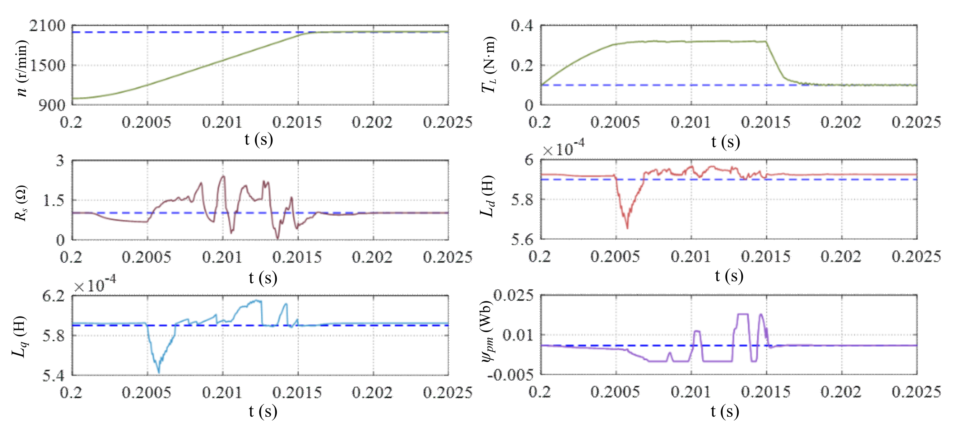
4.2. Dynamic Accuracy of RLS-DSVM-MPC

Figure 12, Figure 13 and Figure 14 show results of parameter identification in the PMSM. Figure 12 shows results when n = 2000   rpm and T L changed from 0.1   N m to 0.2   N m . Figure 13 shows results when T L = 0.1   N m and n changed from 1000   rpm to 2000   rpm . Figure 14 shows results when T L changed from 0.1   N m to 0.2   N m and n changed from 1000   rpm to 2000   rpm .
It can be seen from Figure 12 that the parameters are little affected by the changing load. Additionally, from Figure 13 we know that all the parameters are greatly influenced by the change of velocity. Comparing Figure 12, Figure 13 and Figure 14, we see that the identification of parameters are little affected by the load, and are greatly affected by the velocity. When velocity changes, the identified parameters have poor accuracy.

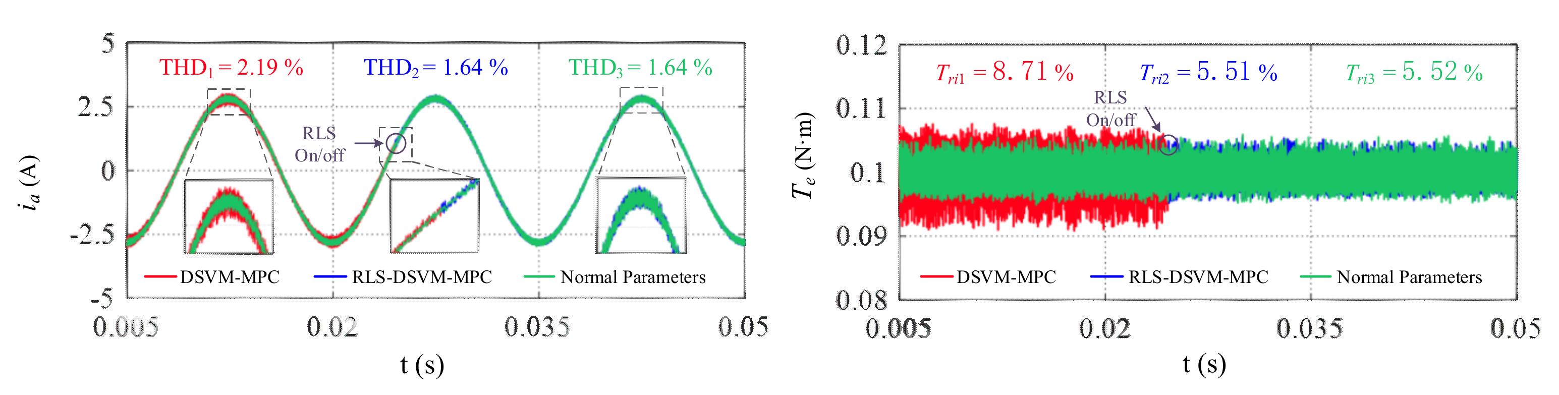
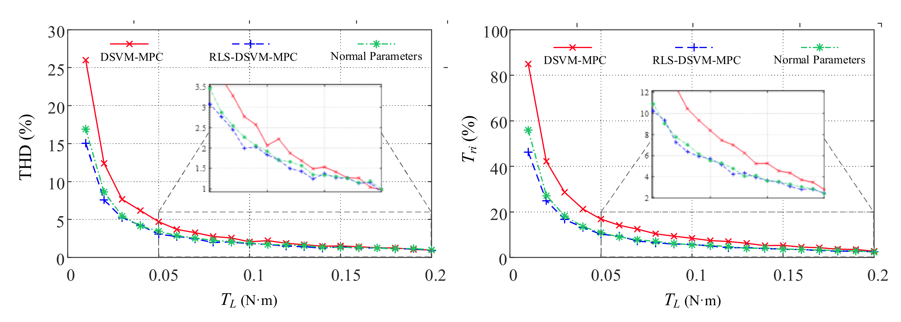
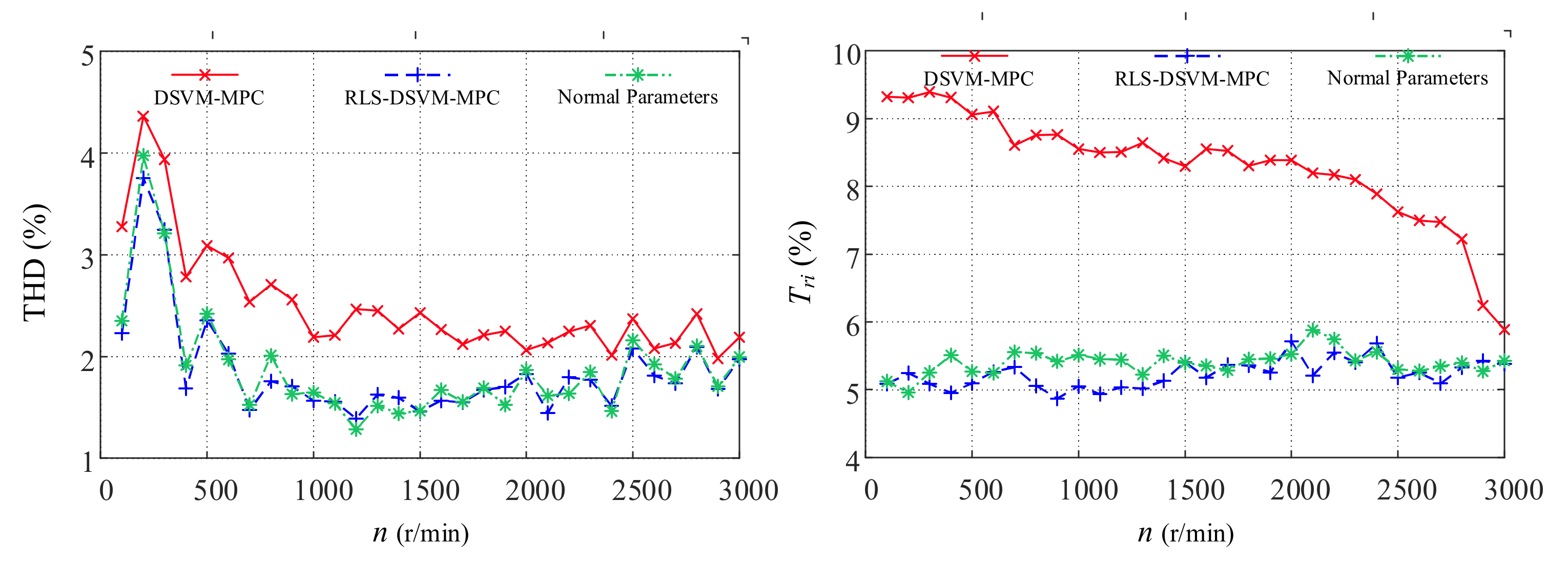
4.3. Performance Analysis of DSVM-MPC and RLS-DSVM-MPC

The ripple of current is represented by THD (Total Harmonic Distortion), which can be expressed as
THD ( % ) = I h m n I f d m × 100 % = I 2 2 + I 3 2 + + I n 2 I 1 2 × 100 %
where:
  • I h m n —the harmonic component,
  • I f d m —the fundamental component,
  • I n —the n th harmonic.
The torque ripple is indicated by T r i , which can be expressed as
T r i = T max T ref + T min T ref 2 T ref × 100 %
where:
  • T max —the maximum value of the torque,
  • T min —the minimum value of the torque,
  • T ref —the value of the normal torque.
To study the influence of different parameters on performance, every parameter was tested with DSVM-MPC, respectively. The tested parameter’s value was set k times the normal value, and the coefficient k changed from 0.1 to 3 by step 0.1. Figure 15 shows the results of the study.
It can be seen from Figure 15 that L q and ψ p m have greater impact on the performance than R s and L d , and DSVM-MPC can obtain the optimal performance only through the accurate parameters.
Figure 16 shows the performance of DSVM-MPC and RLS-DSVM-MPC. The parameters were all set two-times the normal value, while n = 1000   rpm and T L = 0.1   N m . In addition, the normal parameters was set as a control group.
It can be seen from Figure 16 that the performance of RLS-DSVM-MPC is significantly better than DSVM-MPC, and is similar to the normal parameter.
Figure 17 and Figure 18 show the performance of DSVM-MPC and RLS-DSVM-MPC under more conditions. Figure 17 shows results when n = 2000   rpm and T L was set from 0.01   N m to 0.2   N m by step 0.01   N m . Figure 18 shows results when T L = 0.1   N m and n was set from 100   rpm to 3000   rpm by step 100   rpm .
Comparing Figure 16, Figure 17 and Figure 18, we see that the performance of RLS-DSVM-MPC is able to follow that of the normal parameters under almost every conditions. In other words, there are very little difference between the estimated PMSM parameters and the real parameters, and the proposed RLS-DSVM-MPC can meet the requirement of predict parameters in high accuracy.

5. Conclusions

This paper extended the research on DSVM-MPC. The main contributions of this paper can be concluded as following three aspects.
(1)
RLS parameter identification was proposed to predict the PMSM parameters. Through the proposed method, the PMSM parameters can be identified accurately. and compared with the traditional DSVM-MPC, the proposed RLS-DSVM-MPC has a much better control performance.
(2)
A preselection method for candidate voltage vectors in DSVM were introduced, it can reduce the number of candidate voltage vectors from 38 to 13, and greatly release the computational burden of DSVM-MPC.
(3)
Through the results of simulation, we found that the accuracy of identified parameters are mainly affected by velocity while rarely affected by load, and the accuracy in high velocity is better than that in low velocity.

Author Contributions

Conceptualization, J.W.; methodology, J.W., Z.X. and H.Y.; software, J.W. and H.Y.; validation, J.W. and H.Y.; formal analysis, H.Y. and Z.X.; investigation, H.Y. and Z.X.; resources, J.W.; data curation, H.Y.; writing—original draft preparation, J.W. and H.Y.; writing—review and editing, H.Y. and J.W.; visualization, H.Y.; supervision, J.W.; project administration, J.W.; funding acquisition, J.W. All authors have read and agreed to the published version of the manuscript.

Funding

The work is funded by National Natural Science Foundation of China under Grant 61873079 and Key Research and Development Plan of Zhejiang Province of China under Grant 2021C03034.

Institutional Review Board Statement

Not applicable.

Informed Consent Statement

Not applicable.

Data Availability Statement

Not applicable.

Conflicts of Interest

The authors declare no conflict of interest.

References

  1. Wang, H.; Leng, J. Summary on development of permanent magnet synchronous motor. In Proceedings of the Chinese Control and Decision Conference (CCDC), Shenyang, China, 9–11 June 2018; pp. 689–693. [Google Scholar]
  2. Ichikawa, S.; Tomita, M.; Doki, S.; Okuma, S. Sensorless control of permanent-magnet synchronous motors using online parameter identification based on system identification theory. IEEE Trans. Ind. Electron. 2006, 53, 363–372. [Google Scholar] [CrossRef]
  3. Casadei, D.; Profumo, F.; Serra, G.; Tani, A. FOC and DTC: Two viable schemes for induction motors torque control. IEEE Trans. Power Electron. 2002, 17, 779–787. [Google Scholar] [CrossRef] [Green Version]
  4. Singh, G.K.; Nam, K.; Lim, S.K. A simple indirect field-oriented control scheme for multiphase induction machine. IEEE Trans. Ind. Electron. 2005, 52, 1177–1184. [Google Scholar] [CrossRef]
  5. Bao, G.; Qi, W.; He, T. Direct Torque Control of PMSM with Modified Finite Set Model Predictive Control. Energies 2020, 13, 234. [Google Scholar] [CrossRef] [Green Version]
  6. Buja, G.S.; Kazmierkowski, M.P. Direct torque control of PWM inverter-fed AC motors-a survey. IEEE Trans. Ind. Electron. 2004, 51, 744–757. [Google Scholar] [CrossRef]
  7. Zhu, Z.Q.; Liang, D.; Liu, K. Online parameter estimation for permanent magnet synchronous machines: An overview. IEEE Access 2021, 9, 59059–59084. [Google Scholar] [CrossRef]
  8. Vazquez, S.; Rodriguez, J.; Rivera, M.; Franquelo, L.G.; Norambuena, M. Model predictive control for power converters and drives: Advances and trends. IEEE Trans. Ind. Electron. 2016, 64, 935–947. [Google Scholar] [CrossRef] [Green Version]
  9. Leon, J.I.; Kouro, S.; Franquelo, L.G.; Rodriguez, J.; Wu, B. The essential role and the continuous evolution of modulation techniques for voltage-source inverters in the past, present, and future power electronics. IEEE Trans. Ind. Electron. 2016, 63, 2688–2701. [Google Scholar] [CrossRef]
  10. Judewicz, M.G.; González, S.A.; Echeverría, N.I.; Fischer, J.R.; Carrica, D.O. Generalized predictive current control (GPCC) for grid-tie three-phase inverters. IEEE Trans. Ind. Electron. 2015, 63, 4475–4484. [Google Scholar] [CrossRef]
  11. Almér, S.; Mariethoz, S.; Morari, M. Sampled data model predictive control of a voltage source inverter for reduced harmonic distortion. IEEE T. Contr. Syst. T. 2012, 21, 1907–1915. [Google Scholar] [CrossRef]
  12. Geyer, T.; Quevedo, D.E. Multistep finite control set model predictive control for power electronics. IEEE Trans. Power Electron. 2014, 29, 6836–6846. [Google Scholar] [CrossRef]
  13. Vazquez, S.; Marquez, A.; Aguilera, R.; Quevedo, D.; Leon, J.I.; Franquelo, L.G. Predictive optimal switching sequence direct power control for grid-connected power converters. IEEE Trans. Ind. Electron. 2014, 62, 2010–2020. [Google Scholar] [CrossRef] [Green Version]
  14. Kouro, S.; Cortés, P.; Vargas, R.; Ammann, U.; Rodríguez, J. Model predictive control—A simple and powerful method to control power converters. IEEE Trans. Ind. Electron. 2008, 56, 1826–1838. [Google Scholar] [CrossRef]
  15. Geyer, T.; Beccuti, G.A.; Papafotiou, G.; Morari, M. Model predictive direct torque control of permanent magnet synchronous motors. In Proceedings of the 2010 IEEE Energy Conversion Congress and Exposition, Atlanta, GA, USA, 12–16 September 2010; pp. 199–206. [Google Scholar]
  16. Rodríguez, J.; Kennel, R.M.; Espinoza, J.R.; Trincado, M.; Silva, C.A.; Rojas, C.A. High-performance control strategies for electrical drives: An experimental assessment. IEEE Trans. Ind. Electron. 2011, 59, 812–820. [Google Scholar] [CrossRef]
  17. Zhang, Y.; Yang, H. Model predictive torque control of induction motor drives with optimal duty cycle control. IEEE Trans. Power Electron. 2014, 29, 6593–6603. [Google Scholar] [CrossRef]
  18. Casadei, D.; Serra, G.; Tani, K. Implementation of a direct control algorithm for induction motors based on discrete space vector modulation. IEEE Trans. Power Electron. 2000, 15, 769–777. [Google Scholar] [CrossRef]
  19. Wei, X.; Chen, D.; Zhao, C. Minimization of torque ripple of direct-torque controlled induction machines by improved discrete space vector modulation. Electr. Pow. Syst. Res. 2004, 72, 103–112. [Google Scholar] [CrossRef]
  20. Vazquez, S.; Aguilera, R.P.; Acuna, P.; Pou, J.; Leon, J.I.; Franquelo, L.G.; Agelidis, V.G. Model predictive control for single-phase NPC converters based on optimal switching sequences. IEEE Trans. Ind. Electron. 2016, 63, 7533–7541. [Google Scholar] [CrossRef] [Green Version]
  21. Zhou, Z.; Xia, C.; Yan, Y.; Wang, Z.; Shi, T. Torque ripple minimization of predictive torque control for PMSM with extended control set. IEEE Trans. Ind. Electron. 2017, 64, 6930–6939. [Google Scholar] [CrossRef]
  22. Hassine, I.M.B.; Naouar, M.W.; Mrabet-Bellaaj, N. Model predictive-sliding mode control for three-phase grid-connected converters. IEEE Trans. Ind. Electron. 2016, 64, 1341–1349. [Google Scholar] [CrossRef]
  23. Wang, Y.; Wang, X.; Xie, W.; Wang, F.; Dou, M.; Kennel, R.M.; Gerling, D. Deadbeat model-predictive torque control with discrete space-vector modulation for PMSM drives. IEEE Trans. Ind. Electron. 2017, 64, 3537–3547. [Google Scholar] [CrossRef]
  24. Moon, H.C.; Lee, J.S.; Lee, K.B. A robust deadbeat finite set model predictive current control based on discrete space vector modulation for a grid-connected voltage source inverter. IEEE T. Energy Conver. 2018, 33, 1719–1728. [Google Scholar]
  25. Wang, T.; Liu, C.; Lei, G.; Guo, Y.; Zhu, J. Model predictive direct torque control of permanent magnet synchronous motors with extended set of voltage space vectors. IET Electr. Power App. 2017, 11, 1376–1382. [Google Scholar] [CrossRef]
  26. Amiri, M.; Milimonfared, J.; Khaburi, D.A. Predictive torque control implementation for induction motors based on discrete space vector modulation. IEEE Trans. Ind. Electron. 2018, 65, 6881–6889. [Google Scholar] [CrossRef]
  27. Lin, F.J.; Chen, S.Y.; Lin, W.T.; Liu, C.W. An online parameter estimation using current injection with intelligent current-loop control for ipmsm drives. Energies 2021, 14, 8138. [Google Scholar] [CrossRef]
  28. Rahman, K.M.; Hiti, S. Identification of machine parameters of a synchronous motor. IEEE Trans. Ind. Appl. 2005, 41, 557–565. [Google Scholar] [CrossRef]
  29. Brosch, A.; Hanke, S.; Wallscheid, O.; Böcker, J. Data-driven recursive least squares estimation for model predictive current control of permanent magnet synchronous motors. IEEE Trans. Power Electron. 2020, 36, 2179–2190. [Google Scholar] [CrossRef]
Figure 1. Distribution of basic and virtual voltage vectors.
Energies 15 04041 g001
Figure 2. Preselection groups of candidate voltage vectors.
Energies 15 04041 g002
Figure 3. The control structure of RLS-DSVM-MPC.
Energies 15 04041 g003
Figure 4. The procedure to select the optimal voltage vector.
Energies 15 04041 g004
Figure 5. The function to realize RLS parameter identification.
Energies 15 04041 g005
Figure 6. Time sequence of RLS parameter identification and MPC.
Energies 15 04041 g006
Figure 7. The simulation model of RLS-DSVM-MPC.
Energies 15 04041 g007
Figure 8. Parameter identification results at 1000 rpm and 0.1 N·m.
Energies 15 04041 g008
Figure 9. Parameter identification results at 2000 rpm and 0.2 N·m.
Energies 15 04041 g009
Figure 10. Identification accuracy at different velocities.
Energies 15 04041 g010
Figure 11. Identification accuracy at different loads.
Energies 15 04041 g011
Figure 12. Parameter identification results when changes load.
Energies 15 04041 g012
Figure 13. Parameter identification results when changes velocity.
Energies 15 04041 g013
Figure 14. Parameter identification results when changes both load and velocity.
Energies 15 04041 g014
Figure 15. Performance of DSVM-MPC when parameters were set k times the actual value.
Energies 15 04041 g015
Figure 16. Performance of DSVM-MPC and RLS-DSVM-MPC.
Energies 15 04041 g016
Figure 17. Performance of DSVM-MPC and RLS-DSVM-MPC at different loads.
Energies 15 04041 g017
Figure 18. Performance of DSVM-MPC and RLS-DSVM-MPC at different velocities.
Energies 15 04041 g018
Table 1. The members of preselection groups.
Effective Voltage VectorGroup NumberGroup Member
V1I v 100 , v 610 , v 120 , v 110 , v 611 , v 112
V2II v 200 , v 120 , v 230 , v 220 , v 122 , v 223
V3III v 300 , v 230 , v 340 , v 330 , v 233 , v 334
V4IV v 400 , v 340 , v 450 , v 440 , v 344 , v 445
V5V v 500 , v 450 , v 560 , v 550 , v 455 , v 556
V6VI v 600 , v 560 , v 610 , v 660 , v 566 , v 661
Table 2. PMSM parameters in the simulation.
ParametersValueParametersValue
Number of pole pairs4Rated load0.2 N·m
Voltage of the bus24 VStator resistance1.02 Ω
Rated current4 AStator inductance0.59 mH
Rated power62 WMoment of inertia28 g·cm2
Rated speed3000 rpmBack EMF Coefficient4.3 V/krpm
Table 3. PID parameters in the simulation.
ParametersPID
Value0.21.50.0001
Publisher’s Note: MDPI stays neutral with regard to jurisdictional claims in published maps and institutional affiliations.

