Article

Swiveling Magnetization for Anisotropic Magnets for Variable Flux Spoke-Type Permanent Magnet Motor Applied to Electric Vehicles

Department of Electrical Engineering, National Cheng Kung University, Tainan 701, Taiwan
*
Author to whom correspondence should be addressed.
Energies 2022, 15(10), 3825; https://doi.org/10.3390/en15103825
Submission received: 14 April 2022 / Revised: 13 May 2022 / Accepted: 19 May 2022 / Published: 23 May 2022
(This article belongs to the Topic Application of Innovative Power Electronic Technologies)

Abstract

:
This paper investigates the application of anisotropic low-coercive force (LCF) magnets to a novel variable-flux spoke-type permanent magnet synchronous motor (VFS-PMSM) for electrical vehicles with a wide speed range. In the VFS-PMSM, flux is regulated by swiveling the magnetization of the anisotropic LCF magnets instead of directly magnetizing or demagnetizing them. The previously proposed VFS-PMSM uses only isotropic LCF magnets for easily swiveling the magnetic pole direction, resulting in lower torque density. The challenge thus lies in the feasibility to swivel the magnetic pole direction of the anisotropic LCF magnet, and the impact of the different magnetization strengths of the anisotropic magnets on the motor performance. This paper first studies the feasibility to swivel the magnetization direction of anisotropic LCF magnets through experiments. It is confirmed that the magnetization direction can be successfully swiveled by 90 degrees with a reduced external magnetizing field. Then, two VFS-PMSM topologies and various rotor configurations are compared in terms of key performance indices to determine critical sizing factors for performance enhancement. Finite element analysis is used for simulations. In comparison with the VFS-PMSM equipped with isotropic LCF magnets, the maximum torque of the proposed topology can be improved for the same flux adjustment ability. Alternatively, the flux adjustment ability can also be enhanced by 37.43% for the same maximum torque.

1. Introduction

Electric vehicles (EVs) have been rapidly developed in recent years due to the growing concerns about environmental protection and the demand for green transportation. Traction motors are treated as key to electric vehicle performance. Interior Permanent Magnet Synchronous Motors (IPMSM) are a mature candidate for EV tractions with their merits of high torque density and high efficiency [1,2], and therefore, they have been widely studied. Huynh et al. analyzed and compared the performances of IPMSMs and permanent-magnet-assisted synchronous reluctance machines (PMa-SynRMs) on constant power speed range (CPSR) for EV applications [3]. Kim et al. studied the shape parameters of IPMSMs and improved their efficiency by about 1% [4]. However, common EVs usually face various road conditions, such as high torque for hill climbing or high speed for long-distance cruises, and the constant flux linkage contributed by permanent magnets (PMs) may limit the speed of IPMSMs [5]. Flux-weakening control is usually used to weaken the field and increase the speed range [6,7]. Inoue et al. analyzed the performance of current control and direct torque control (DTC) with flux-weakening applied and summarized their advantages and disadvantages [8]. However, weakening the flux would sacrifice part of the stator current to suppress flux and lead to extra copper loss. Additionally, motor mathematical models are often needed to calculate the current phase advance angle, and the errors are likely to occur under dynamic operations [9]. The motor speed can also be expanded with an auxiliary coil to accurately control rotor magnetic flux [10,11]. Some designs, such as the double excited synchronous machine [12] and the synchronous/permanent magnet hybrid AC machine [13], place the auxiliary windings and permanent magnets in series or parallel. Nevertheless, the presence of the slip rings is the main drawback of this type of motor. To mitigate the problem of slip rings, a doubly salient PM motor was proposed [14], which placed the auxiliary windings, stator windings, and PMs in the stator, resulting in the stator being prone to saturation. A motor having an auxiliary winding with a hybrid radial and axial magnetic circuit was proposed [15,16]; however, the torque and power density may likely reduce, and the power consumption and copper loss are still inevitable for weakening the field [17]. The appearance of memory motors, also known as variable flux motors (VFMs), effectively resolves the above problems [18]. In the memory motors, an impulse current can be generated by stator windings to change the magnetization state (MS) of a low coercive force (LCF) magnet to achieve the purpose of adjusting air gap flux density. The loss caused by the impulse current to change the MS of the LCF magnet is almost negligible for motors in operation [19].
Low coercive force (LCF) magnets (e.g., AlNiCo) are often used in the VFMs to reduce the impulse current needed for magnetization or demagnetization of the magnets. However, using only LCF magnets is prone to unexpected demagnetization [20]. To prevent this situation, Kato et al. [21] proposed a variable-flux flux-intensifying interior permanent magnet machine (VFI-IPMM), where demagnetization can be avoided because the d-axis current is positive at heavy load. To further enhance the torque density of the VFMs, various topologies of hybrid variable flux motors (H-VFM) combining LCF magnets and high coercive force (HCF) magnets were proposed [22,23]. The H-VFM rotor can be divided into series and parallel configurations according to the arrangements of permanent magnets. The series type of H-VFM [24] possesses a higher torque density at low speed since the flux of the HCF and LCF magnets can be combined by the series arrangement. In the series type of H-VFM, a much smaller impulse current is needed to switch the MS of the LCF magnet from flux weakening to enhancing due to the influence of the HCF magnet. Conversely, it requires a larger impulse current to switch from flux enhancing to weakening. For the parallel type of H-VFM [25], an active flux leakage bypass is established which is advantageous for flux regulation. Hua et al. compared the series and parallel types of H-VFMs and revealed that the operating point of the LCF magnet in the parallel type is unstable [26]. To have a stable operation of the LCF magnet and excellent flux regulation ability, a variable-flux permanent-magnet synchronous machine with a quasi-series magnet configuration and passive flux barrier was proposed [27,28]; however, the problem of a large magnetizing current to switch from flux enhancing to weakening is yet to be resolved. Yang et al. proposed a hybrid-magnet-circuit VFM [29,30,31] that combines the advantages of both types of H-VFMs mentioned above to achieve high torque density, good flux adjustment ability, and reduce magnetizing currents. However, the rotor configuration seems complex and requires more expensive HCF rare-earth magnets.
Lee et al. proposed a novel variable flux spoke-type permanent magnet motor (VFS-PMSM) [32], which combines the advantages of the series and parallel types of H-VFMs. The flux regulation can be achieved by swiveling the magnetic pole of the isotropic LCF magnet. By so doing, the flux produced by the LCF magnets is ensured to align with that produced by the HCF magnet, and therefore accidental demagnetization can be avoided. The magnetizing impulse current is also greatly reduced for switching the MS and regulating air gap flux density. However, there is still room for improvement in torque density and flux regulation ability due to the use of the weaker isotropic LCF magnets.
To simultaneously achieve the above-mentioned advantages, i.e., high torque density, excellent flux regulation ability, low demagnetization risk, low magnetizing impulse current demand, high efficiency at high speed, and expanded motor operating range, this paper proposes a novel VFS-PMSM topology combining HCF magnets and anisotropic LCF magnets, instead of the isotropic LCF magnet used in a previous study [32]. The method of swiveling the magnetic pole of the LCF magnet [32] is adopted, which differs from the previously mentioned methods that magnetize/demagnetize the magnets in the same axis [18,19,20,21,22,23,24,25,26,27,28,29,30,31]. It should be noted that there is a significant difference in flux generated and magnetizing field required between the easy and hard axes in the anisotropic magnets. Therefore, it is generally believed that the magnetic pole of an anisotropic magnet cannot be swiveled. This is the key challenge and the major difference from the isotropic design previously reported [32]. In this paper, analyses and experiments are conducted to study the feasibility of swiveling magnetization for the anisotropic magnet applied to the VFS-PMSM. Then the torque density and flux regulation ability of the motor are investigated. Several configurations of the VFS-PMSM are compared to highlight a suitable arrangement to reduce magnetizing current while enhancing the maximum torque and flux regulation ability.
This paper is organized as follows. In Section 2, the characteristics of the proposed variable flux PM motor topologies and the previously developed VFS-PMSM are analyzed and compared. Their features are explained in detail. The feasibility of applying the anisotropic AlNiCo in the VFS-PMSM is experimentally verified in Section 3. In Section 4, the key characteristics of the proposed anisotropic VFS-PMSM with different rotor types are compared by adjusting the sizing parameters of the LCF magnets and HCF magnets. The electromagnetic characteristics of the proposed motor topologies are simulated and compared with other types of motors in Section 5, followed by Section 6 to conclude this paper.

2. Variable Flux PM Motor Topologies and Proposed VFS-PMSM

The VFS-PMSM [32], like the general series and parallel types of H-VFMs, uses both LCF magnets and HCF magnets in the rotor; however, the principal difference of this design is to use the magnetic field excited by the stator to “swivel” the magnetization vector of the LCF magnet to achieve flux regulation. When the flux density of the air gap needs to be enhanced, the impulse current produced by the stator winding generates a magnetizing field on the +d axis (phase advance is −90°) to magnetize the LCF magnet radially. The flux of the HCF magnet is guided to the air gap and the stator through the LCF magnet. To weaken the flux density of the air gap, the impulse current generates a magnetizing field on the -d axis (phase advance is +90°) to swivel the magnetization direction of the LCF magnet to align in the tangential direction. The flux of the HCF magnet is guided to the flux leakage bypass via the LCF magnet. The details for the magnetization of the LCF magnets can be referred to in a previous study [32]. Theoretically, the impulse current applied on the +d or −d axis will not result in an undesirable torque surge. To successfully adjust the air gap flux density of the VFS-PMSM by swiveling the magnetization vector of the LCF magnet (called the “swiveling magnetization technique” in what follows), isotropic AlNiCo was used in the previously developed VFS-PMSM [32] (called the “isotropic VFS-PMSM” in what follows). The magnetic characteristics of isotropic magnets should be the same regardless of the direction of magnetization.
To investigate the feasibility of anisotropic AlNiCo magnets for swiveling magnetization, the demagnetization curves of the isotropic and anisotropic AlNiCo magnets in different directions, as shown in Figure 1, are first measured by a B-H tracer. Both magnets are 10 mm × 10 mm × 10 mm cubes. As shown in Figure 1, the “0°” indicates one side of the cube, and the “90°” is the other. As can be seen, the isotropic magnet has almost identical demagnetization curves in the two directions and its remanence Br and maximum energy product are lower than those in the easy axis of the anisotropic magnets. It should be noted that the swiveling magnetization technique involves the magnetization of an anisotropic LCF magnet in two directions separated by 90° (i.e., either on the easy axis or hard axis), the arrangements of the anisotropic LCF magnet should be considered for magnetizations to regulate the flux and torque production.
One merit of the VFMs is their air gap flux density regulation ability to improve the constant power and high-efficiency operating range. Therefore, the key index used to evaluate a VFM is the highest torque at flux enhancing state and the back electromotive force (back EMF) difference between the flux enhancing and weakening cases at a certain speed. In the enhancing state, the motor air gap flux density is maximized and in the weakening state, it is minimized. This paper proposes two topologies that apply anisotropic AlNiCo to the VFS-PMSM, as shown in Figure 2 (called the “anisotropic VFS-PMSM” in what follows). In Topology I, the easy axis of the anisotropic magnet is arranged to be aligned with the radial direction of the rotor, as shown in Figure 2b while the hard axis of the anisotropic magnet in Topology II is aligned radially (Figure 2c).

2.1. Torque Generation

The material properties and dimensions of the motor are given in Table 1. As can be seen, the difference between Topologies I, II, and the isotropic VFS-PMSM only lie in the LCF magnets used. The AlNiCo magnet (model: LNGT 18) is used for the isotropic VFS-PMSM, and the anisotropic AlNiCo magnet (LNGT 40) is for Topologies I and II. The performance of the three models in Figure 2 is compared by simulations using finite element analysis (FEA) of transient electromagnetic fields (FEA, ANSYS Maxwell). The material properties of the LCF magnets (e.g., the hysteresis loops) used in the simulations are obtained from the measurements conducted in Section 3. The material properties of the HCF magnets can be found in the database of the FEA software. Note that the two anisotropic models are only preliminary designs by directly replacing the isotropic magnets with the anisotropic magnets. As shown in Figure 3, the maximum torque produced at flux enhancing is compared between the isotropic VFS-PMSM and Topologies I and II of the anisotropic VFS-PMSM. As can be seen, the isotropic VFS-PMSM produces larger torque than the other two, and Topology II has slightly higher torque than Topology I. This seems that the application of the anisotropic magnets is not effective; however, as previously mentioned, it would not be appropriate to directly replace the isotropic magnets with anisotropic ones due to their different strengths in different directions, as indicated in Figure 1. Therefore, with slightly lower peak torque than that of the isotropic VFS-PMSM, the topology with anisotropic LCF magnets will be optimized in a later section.

2.2. Flux Regulation Ability

The flux regulation ability can be indirectly evaluated through the difference in the back EMF between the flux enhancing and weakening states. The back EMF difference E r is defined as:
E r   =   E +     E
where E + is the back EMF at flux enhancing and E is that at flux weakening. Note that the air gap flux density is considered proportional to the back EMF at the same speed (assuming no saturation), and thus the back EMFs at flux enhancing and weakening represent the maximum and minimum air gap flux densities, respectively. The larger the back EMF difference is, the better the flux regulation ability is. Figure 4 shows the simulated back EMF of the isotropic VFS-PMSM, Topologies I and II at flux enhancing and weakening, and E r of the three cases can be obtained and expressed by E r _ i s o _ V F S , E r _ T I and E r _ T I I , respectively. As shown in Figure 4, E r _ T I I is the largest, and E r _ T I is the smallest.

2.3. Discussion

The correlation between the LCF magnet features and the back EMF difference Er should be investigated. The remanence of the LCF magnets toward the radial and tangential directions (indicated in Figure 2) are considered separately here for their individual contributions to air gap flux. As shown in Table 2, the LCF magnet in Topology I has the largest radial remanence, followed by that of the isotropic VFS-PMSM and then Topology II. It seems that the remanence of the LCF magnet in the radial direction does not directly correlate to the maximum torque production. For the tangential remanence of the LCF magnet, Topology II has the highest, the isotropic VFS-PMSM is the second, and Topology I the least. From these discussions, it can be seen that E r and the flux regulation ability are strongly related to the tangential remanence of the LCF magnet rather than the radial one. This is a key to the arrangement of anisotropic LCF magnets for improving flux regulation ability (placing the easy axis of the LCF magnet tangentially).
For torque production, from the study previously mentioned, the remanence of the LCF magnet should not be the main cause that affects the maximum torque (neither radial nor tangential). It is presumed that the HCF magnet is key to the maximum torque of the motor, and when enhanced, as mentioned, optimization will be conducted.

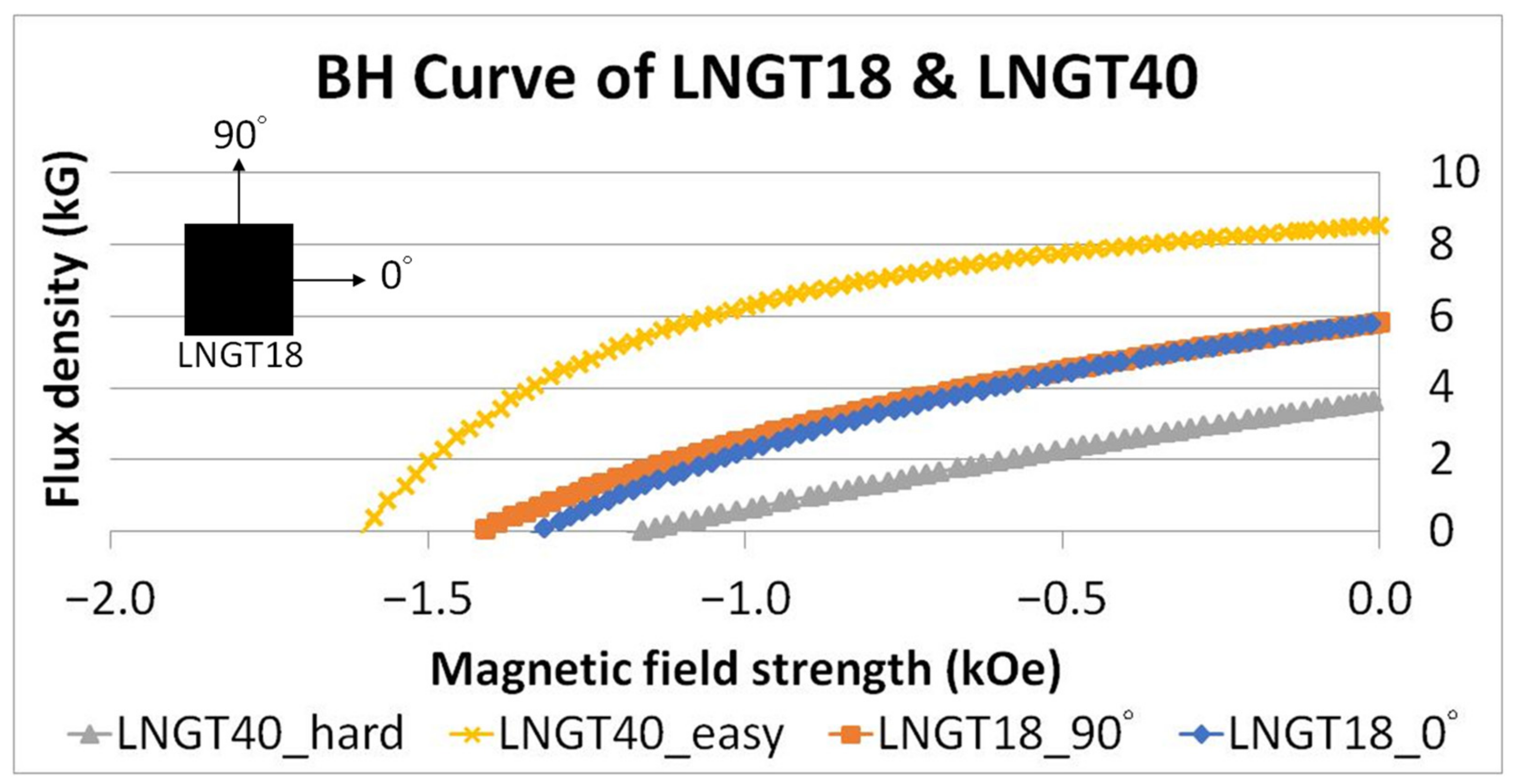
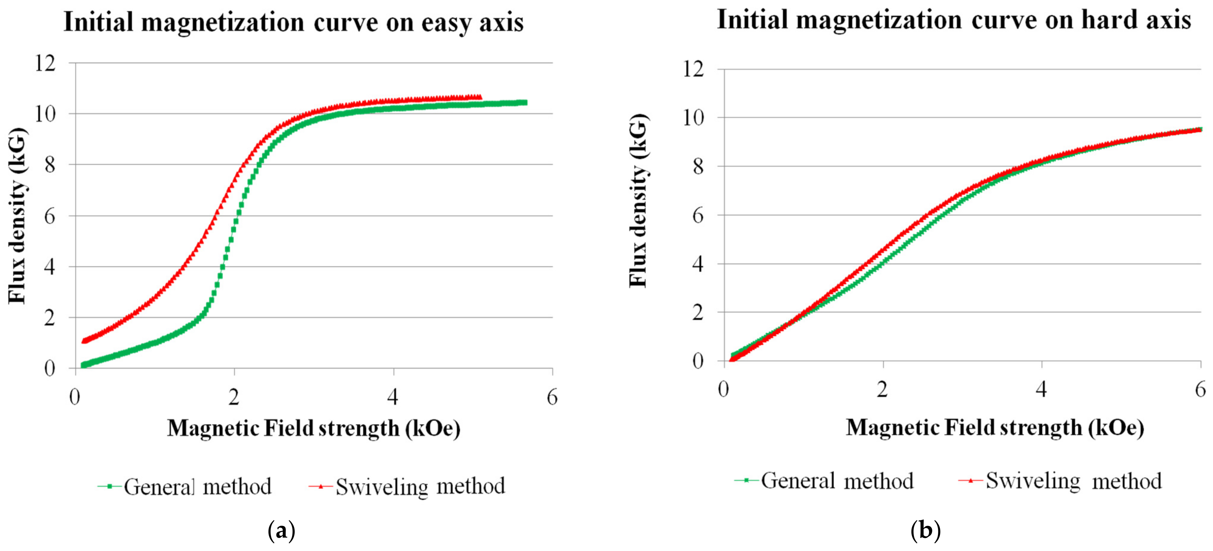
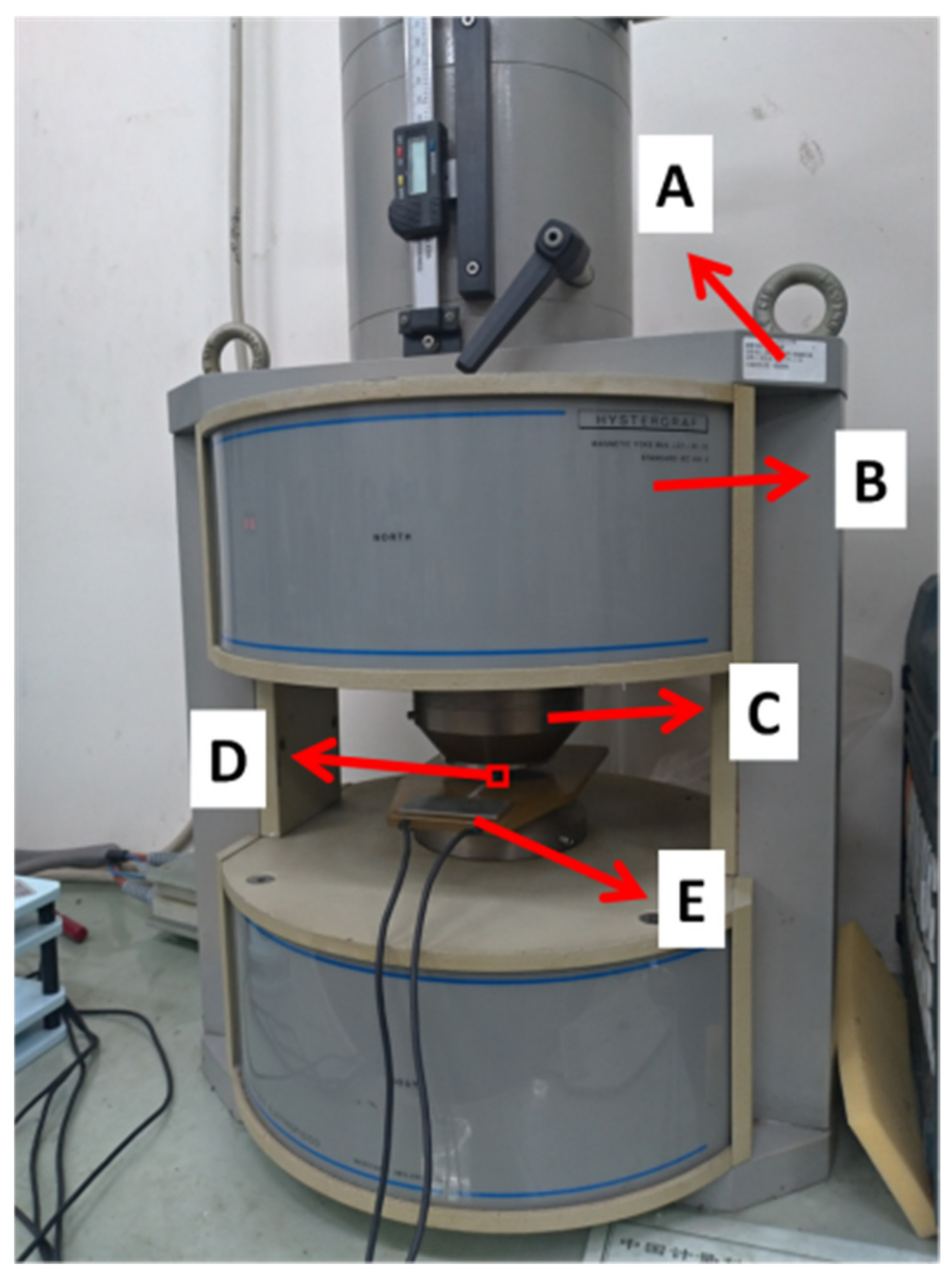
3. Feasibility Verification of Anisotropic AlNiCo Application in VFS-PMSM

The aforementioned VFS-PMSM topologies are studied using anisotropic AlNiCo as the LCF magnet to adjust the air gap flux density. It is generally believed that the easy axis of an anisotropic magnet should only be used for applications as a stronger field can be produced. Furthrmore, for the swiveling magnetization technique, the MS of the anisotropic LCF magnet is required to be switched between the hard axis and easy axis by an external magnetizing field. Therefore, whether the magnetization of an anisotropic magnet can be successfully swiveled should be investigated, and experiments can be conducted for validation. Moreover, the magnetizing field strength required to swivel the magnetization direction should also be tested. Then, the demagnetization curves obtained by the “swiveling magnetization technique” and the “general magnetizing method” (i.e., magnetization in the same axis) can be compared. Note that commercial finite element simulation software is not capable of simulating the swiveling magnetization technique, and thus the following experiments are planned, and the results are obtained.
The magnets to be measured are cube anisotropic AlNiCo magnets LNGT40. The measurements include:
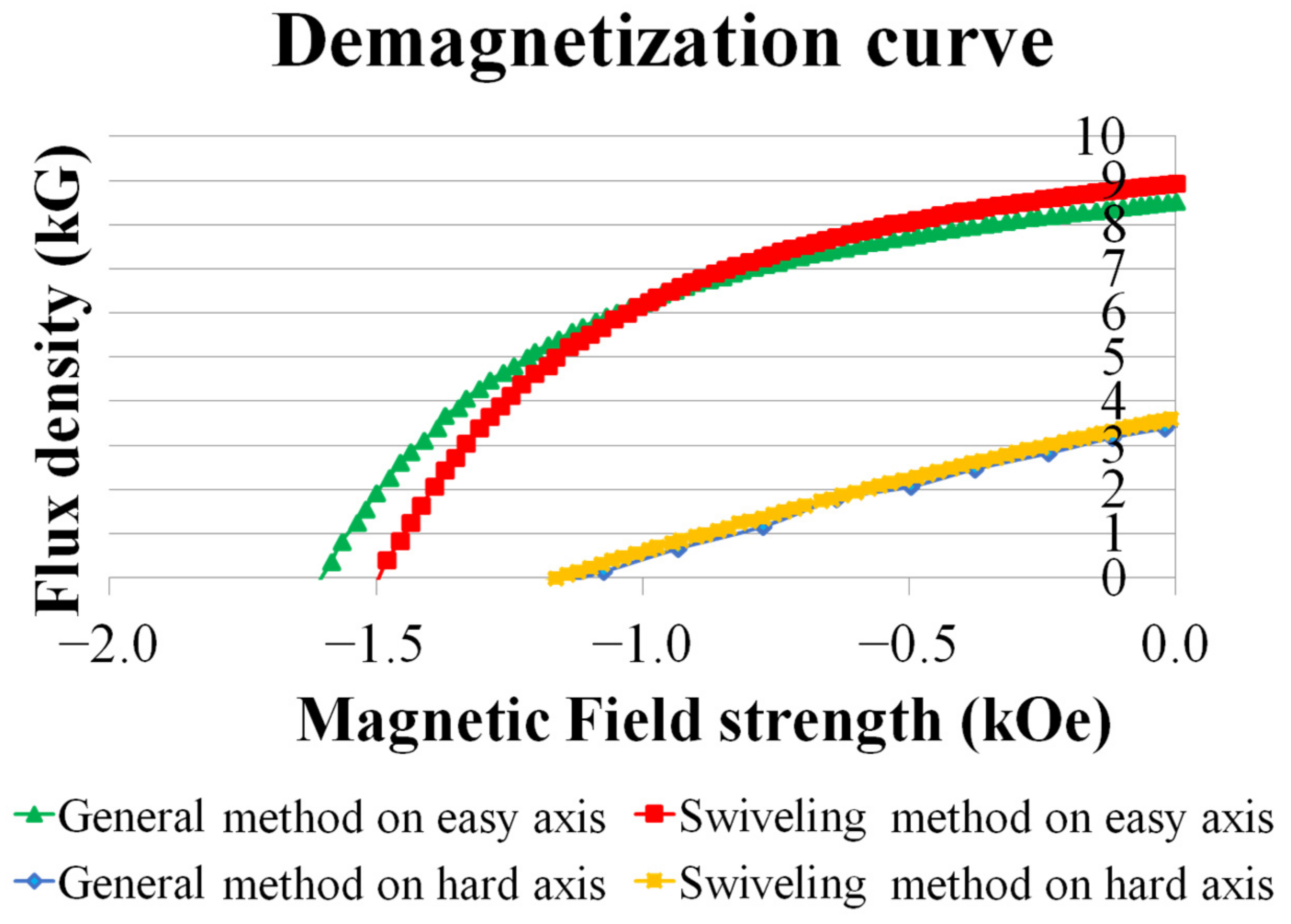
  • The initial magnetization curve and demagnetization curve in the easy axis and hard axis when they are originally unmagnetized (general magnetization method);
  • The initial magnetization curve and demagnetization curve in the hard axis after the magnet is already magnetized in the easy axis (swiveling magnetization technique);
  • The initial magnetization curve and demagnetization curve in the easy axis after the magnet is already magnetized in the hard axis (swiveling magnetization technique).
The experimental setup is shown in Figure 5, where item “A” is the B-H tracer, item “B” is the magnetizing coil, item “C” is the magnet holder, item “D” is the magnet to be measured, and item “E” is the pickup secondary coil. The experimental steps are explained as follows.
(I)
The unmagnetized magnet is placed in the B-H tracer with its easy axis aligned with the pickup coil. The external magnetizing field is slowly increased until the measurement of the initial magnetization curve in the easy axis is completed (general magnetizing method). Then, the coil current is released, and then a sufficiently large external field opposite to the previous magnetizing direction is applied and gradually reduced until the current in the magnetizing coil drops to zero to complete the measurement of the demagnetization curve in the easy axis (general magnetizing method). Then, these are all repeated for the hard axis of another piece of magnet. Moreover, from all these processes there will be two pieces of anisotropic magnets magnetized in different axes.
(II)
The hard axis of the magnet previously magnetized in the easy axis is then placed aligning with the magnetizing and pickup coils. The magnetizing field is gradually increased until saturation to complete the measurement of the initial magnetization curve for the swiveling magnetization technique (turning from the easy axis to the hard axis). Then, after the magnetizing current is released, an opposite magnetizing field being sufficiently large is applied and gradually reduced until the current drops to zero to complete the demagnetization curve measurement for the swiveling magnetization technique.
(III)
Adopting the same process as described in Step 2 but using another piece of magnet previously magnetized in the hard axis, the initial magnetization curve and demagnetization curve with swiveling magnetization turning from the hard axis to the easy axis can be obtained.
From the results obtained via the above steps, the initial magnetization curves in the easy and hard axis by the swiveling magnetization technique and the general method are presented in Figure 6. As can be observed, the swiveling magnetization technique can fully magnetize the magnet with an external magnetizing field smaller than that of the general method in the easy axis. On the hard axis, the swiveling magnetization technique can also magnetize the magnet with a slightly smaller field, as shown in Figure 6b. To show the difference between the two methods clearly, the results in Figure 6 are summarized in Table 3. The MS of the magnet can be defined as 100% when it is fully magnetized, and thus the MS can be expressed by the percentage of magnetization. As can be seen in Table 3, for the MS to achieve 100% in the easy axis, the general magnetization method requires a magnetizing field strength of 4.55 kOe, and for the swiveling method, only 3.32 kOe, which is 27% lower. The comparison in Table 3 shows the magnetizing field strengths required by the two magnetization methods for the MS to achieve 100%, 75%, and 50%. When the magnet is magnetized to 50% MS in the hard axis, the swiveling method can also save 10.4% magnetizing current compared to the general method. Note that the impulse current for magnetization and changing the MS in a VFS-PMSM is generated by its stator winding. Therefore, the smaller the magnetizing field needed, the smaller the inverter capacity required. From Figure 6 and Table 3, the swiveling magnetization technique can effectively reduce the magnetizing field required for producing an equivalent demagnetization curve to that with the general method, as shown in Figure 7. This indicates that the swiveling method can produce the same characteristics of the magnets as the general method does.
Note that from the previous study, the anisotropic LCF magnets with the easy axis aligning tangentially are adopted in the following analyses.

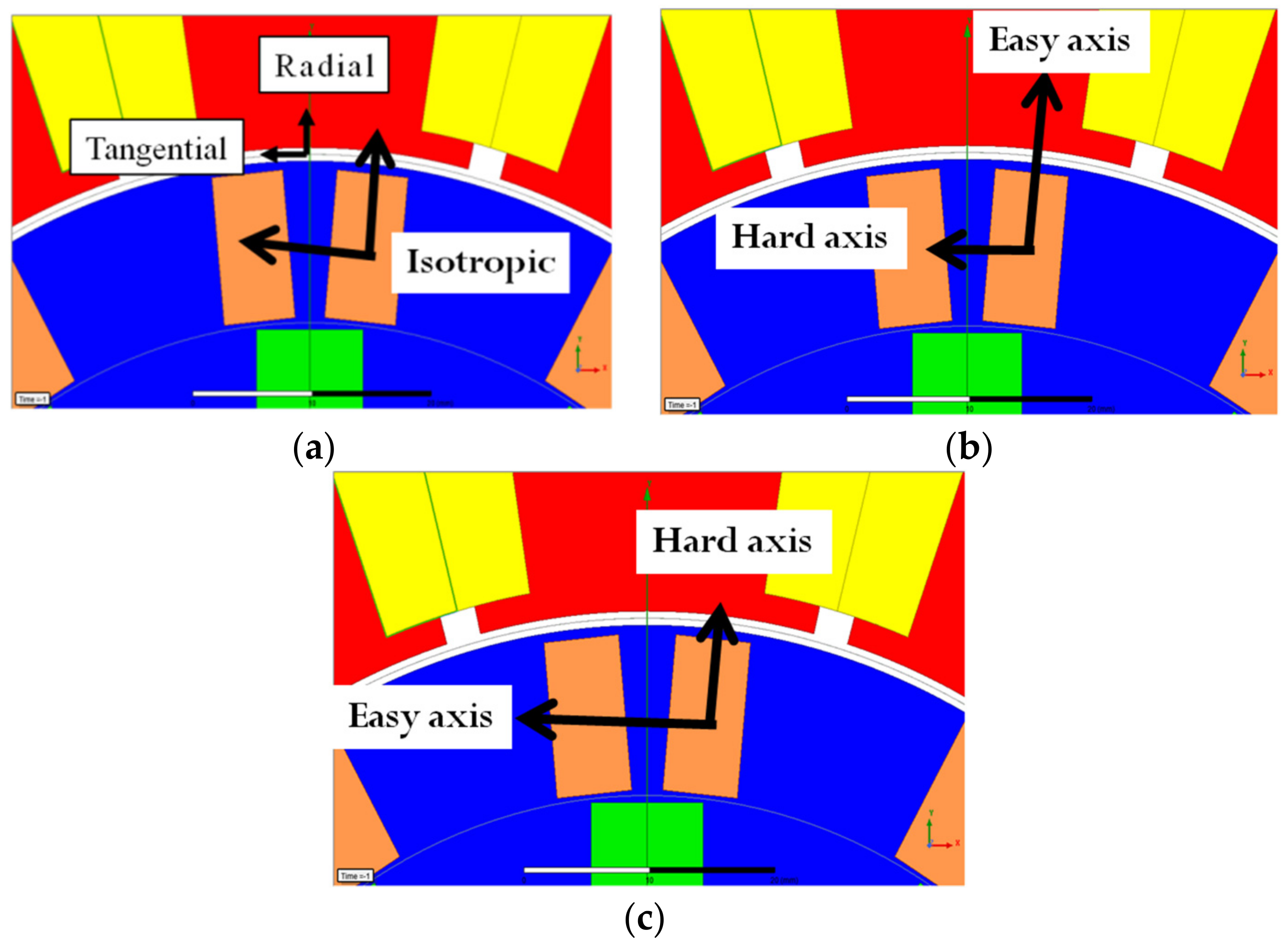
4. Performance Comparison of Anisotropic VFS-PMSM with Different Rotor Configurations
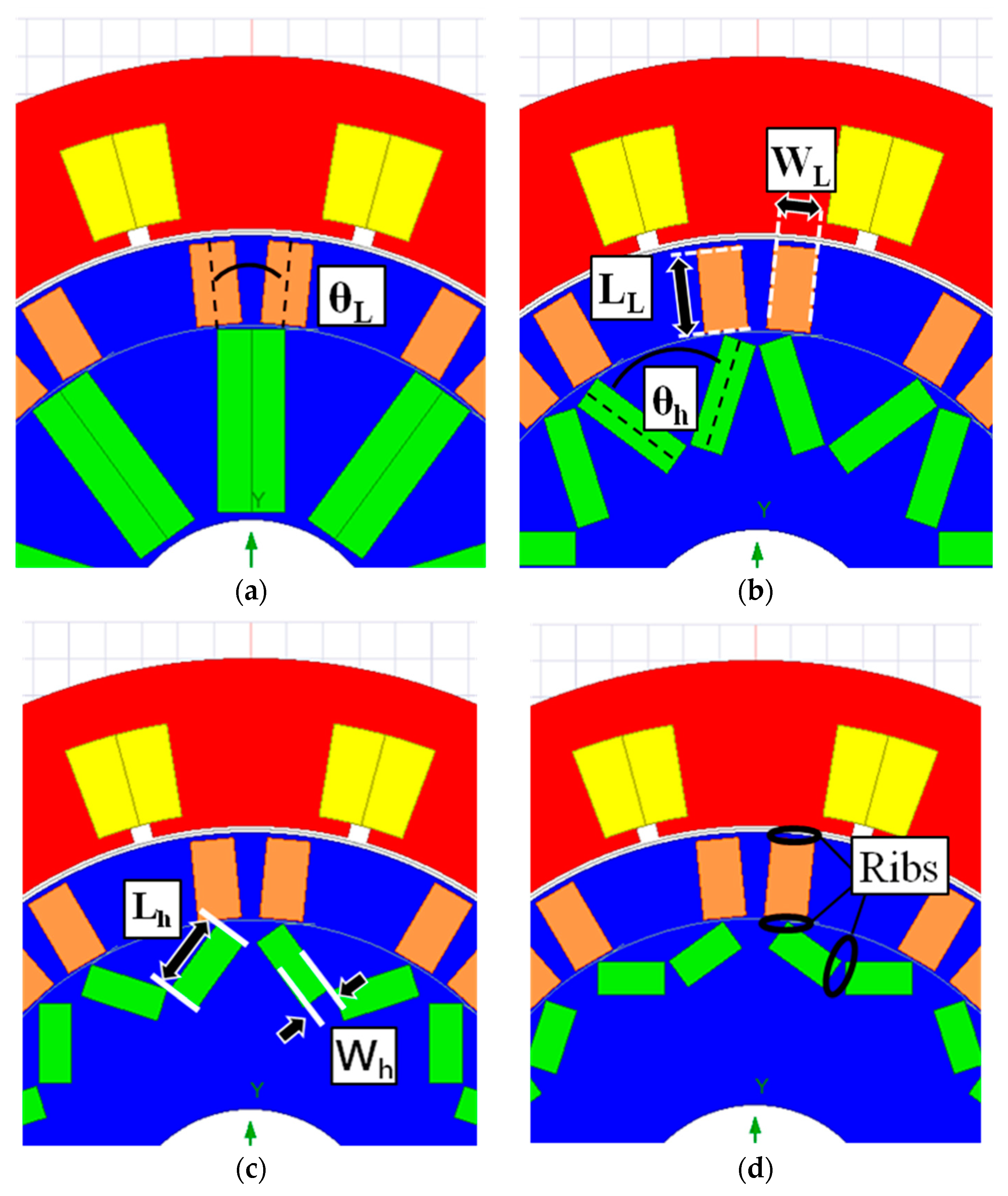
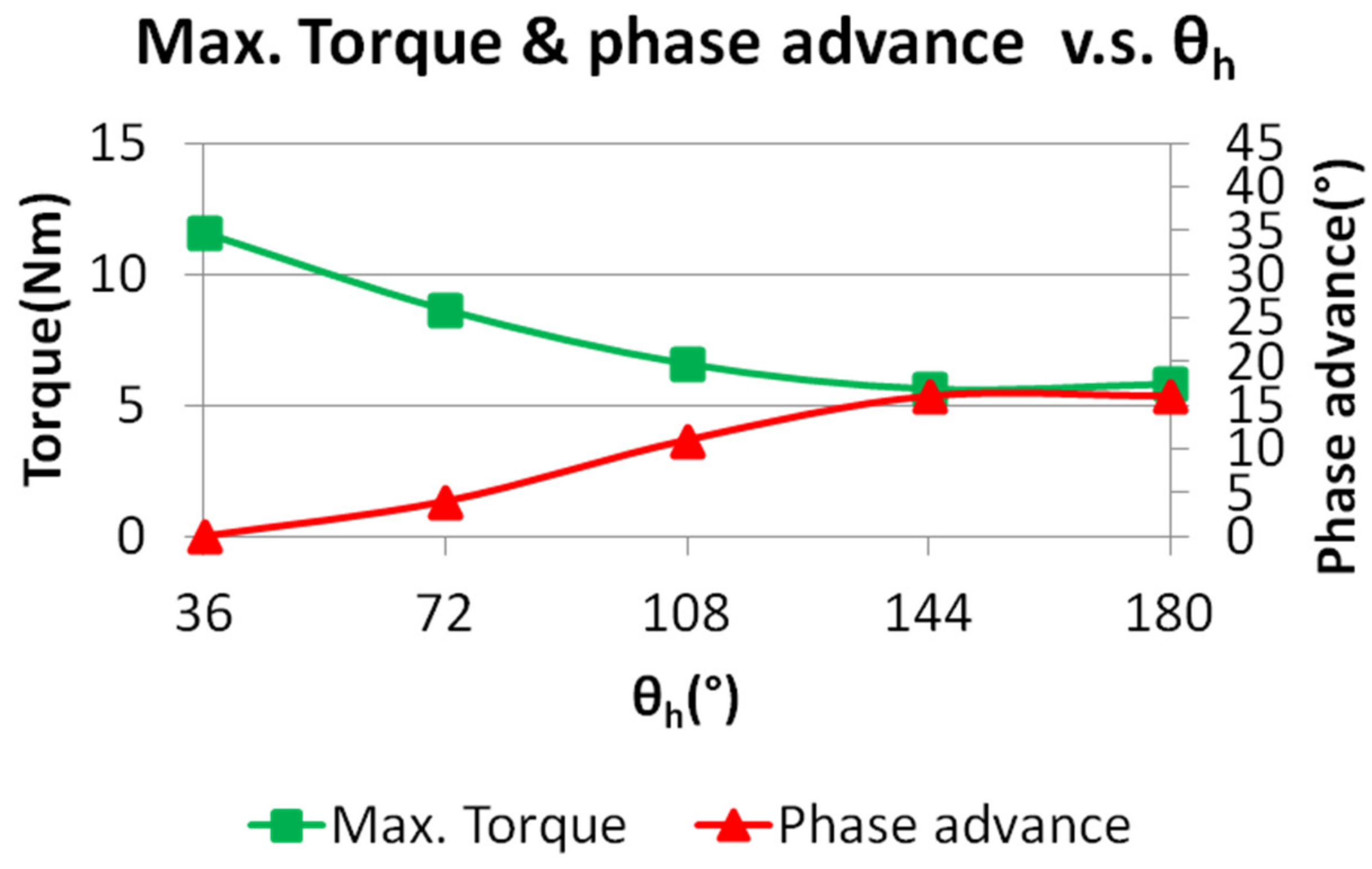
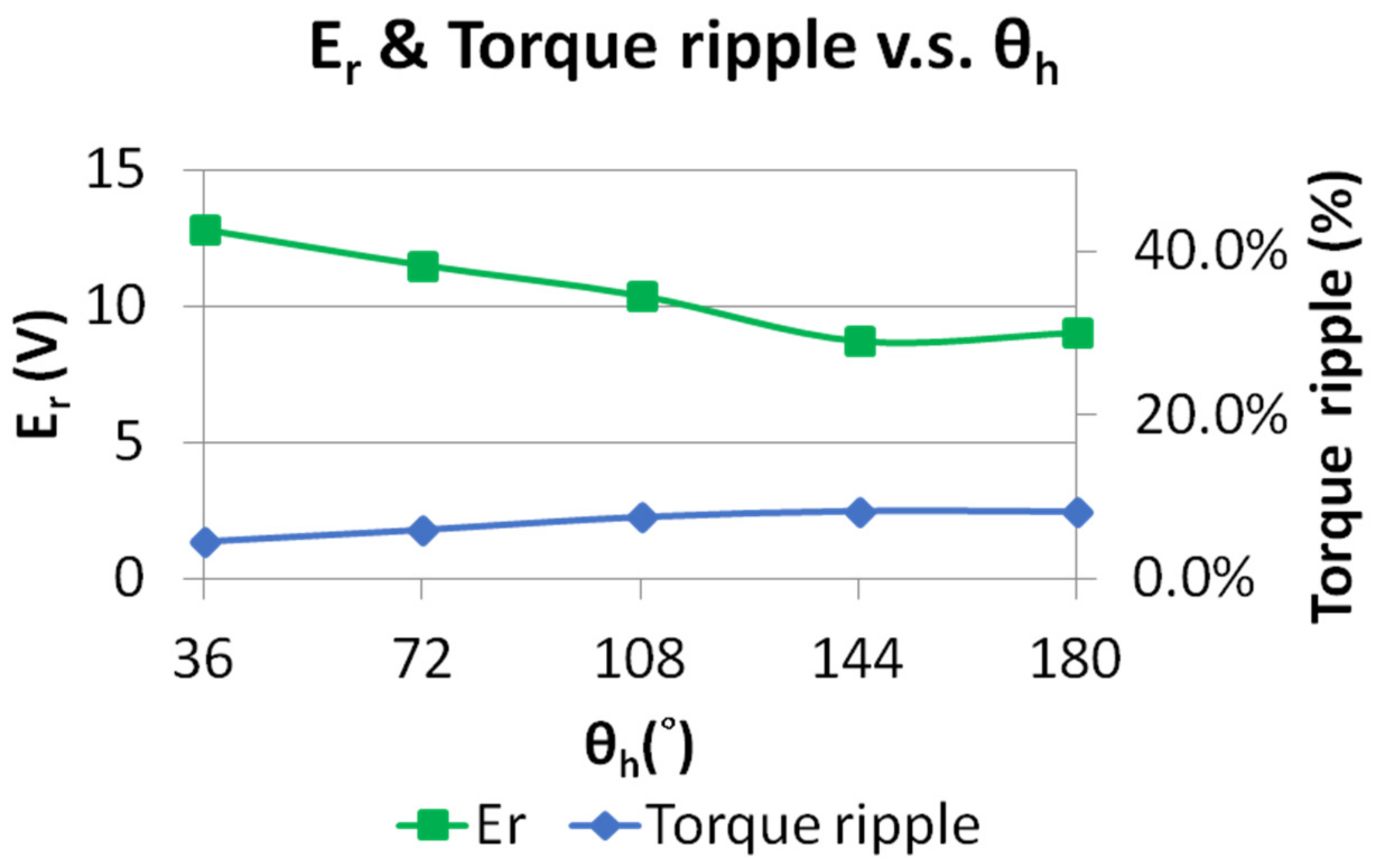
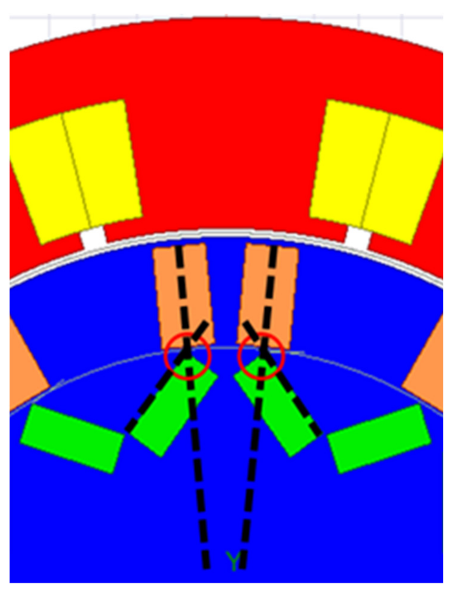
From the discussion in Section 2, the main factor that affects the peak torque of the VFS-PMSM at flux enhancing would be the HCF magnet. Therefore, various HCF magnet configurations in the rotor are studied, covering the flat-type, V-type, and spoke-type magnet arrangements. Their performances are compared based on the same amount of LCF magnets used in terms of maximum torque at flux enhancing, flux regulation ability, and torque ripple at maximum torque. This aims at choosing the most suitable rotor configuration for the VFS-PMSM that would produce high peak torque. Note that as previously mentioned, the LCF magnets here are anisotropic with the easy axis being aligned tangentially.

4.1. Scenario I

The first condition for comparison includes (referring to Figure 8):
  • The size and position of the LCF magnet remain the same;
  • The thickness of the HCF magnet Wh, is fixed;
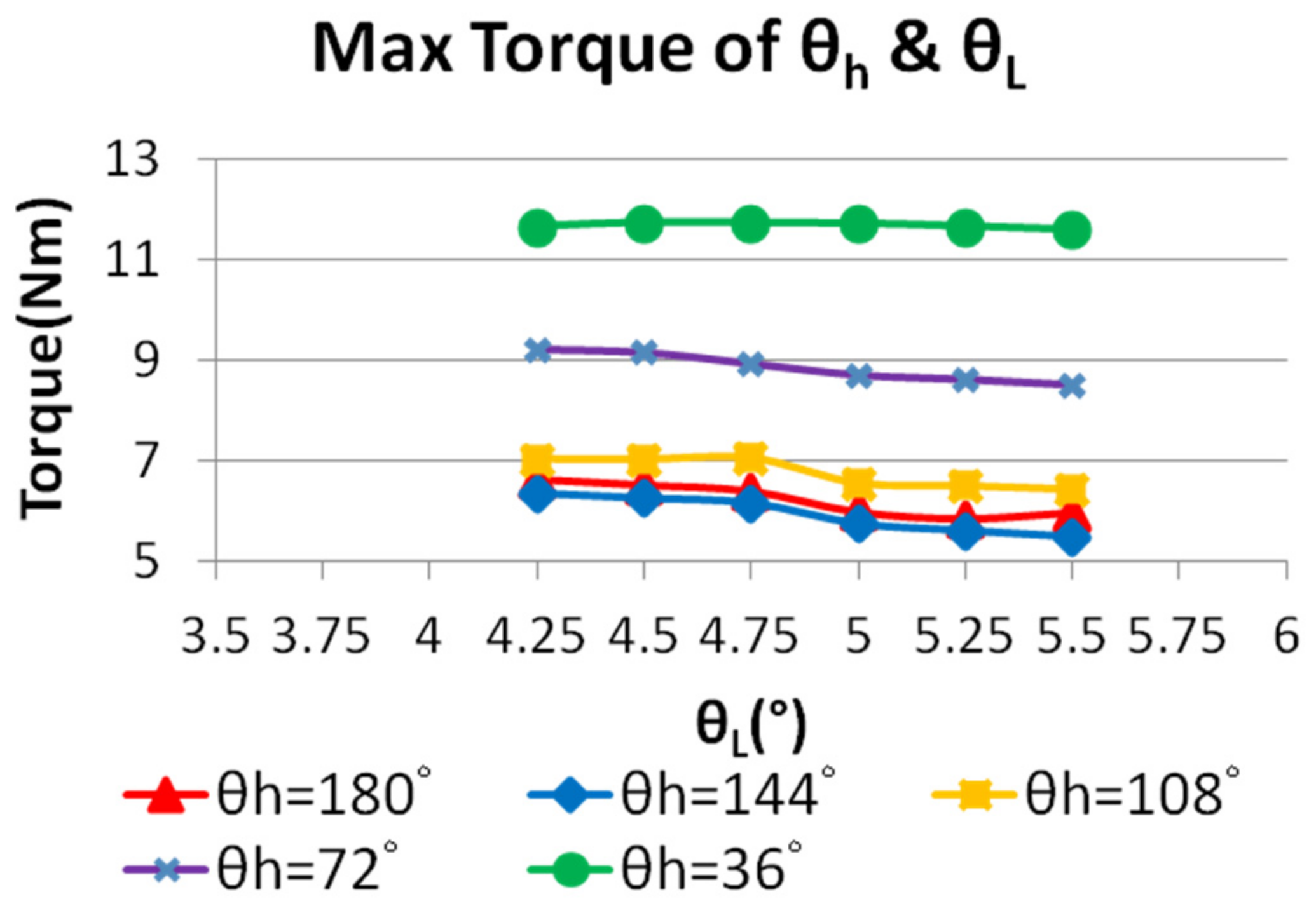
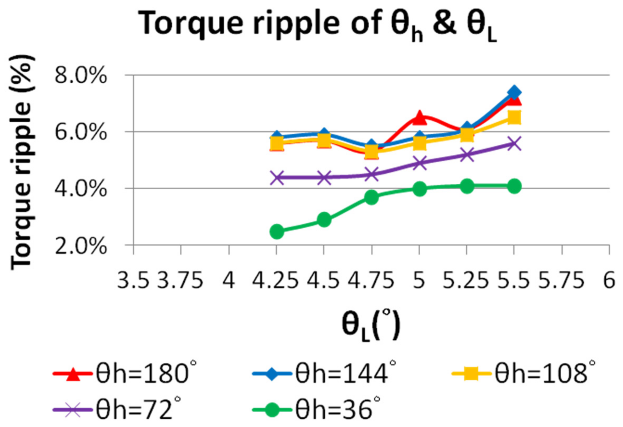
  • The angle θh between the two HCF magnets for one pole is set as a variable.
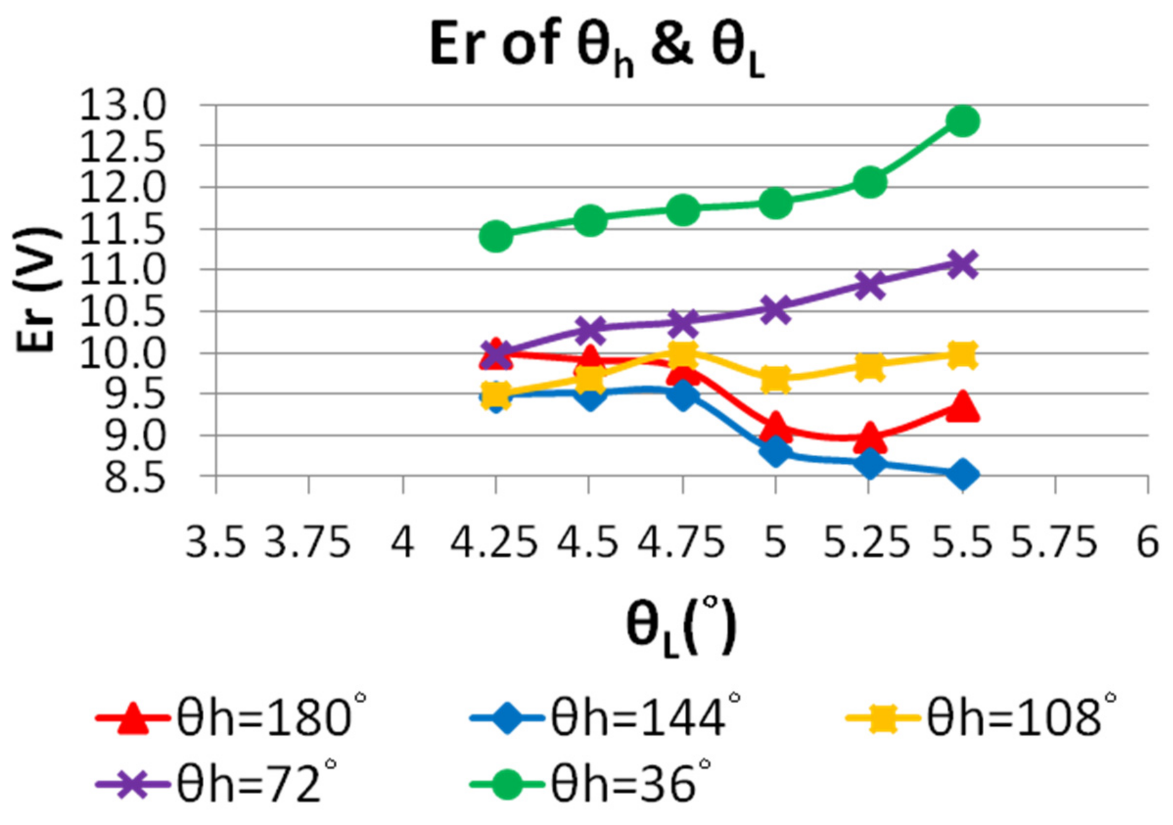
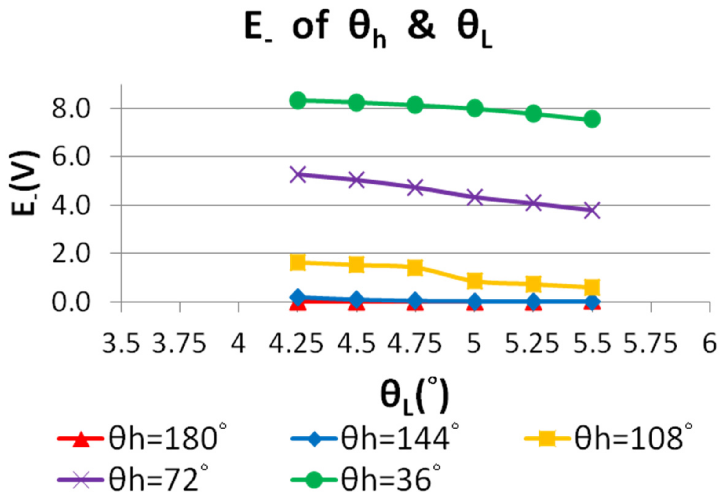
The angle θh for the spoke-type rotor is 36 degrees. For the V-type rotor, three angles are considered: 72, 108, and 144 degrees. The angle is 180° for the flat-type rotor. These rotor configurations are shown in Figure 8.
It can be seen in Figure 9 that as θh increases, the current phase advance to achieve maximum torque per ampere (MTPA) also increases, which means that the proportion of reluctance torque increases. A larger θh brings the HCF magnets closer to the air gap and can provide more torque. However, the maximum torque at flux enhancing decreases with the increase of θh. This is likely because as θh increases and the thickness of the HCF magnet remains, a larger θh leads to a smaller HCF magnet length Lh, which greatly reduces the air gap flux density. As shown in Figure 10, the torque ripple gently rises, and the flux regulation ability decreases as θh increases. The flux concentration factor decreases as θh increases, and the amount of flux leakage will be lower accordingly even if the flux leakage bypass is opened. Therefore, it is believed that the flux adjustment ability will be affected.

4.2. Scenario II

From the discussion for Scenario I, it can be concluded that as θh increases, the maximum torque at flux enhancing decreases. The main reason is that the amount of HCF magnets is reduced as θh increases. To enhance the maximum torque, the angle θL of the LCF magnet is adjusted. In the rotor of the anisotropic VFS-PMSM, the LCF magnet should be placed in a location related to the HCF magnet, as indicated in Figure 11. The reason for this arrangement is to allow the MS of the LCF magnet to be easily changed by the swiveling magnetization technique.
In addition, the minimum width of the ribs is 0.5 mm, as shown in Figure 8d, by considering the manufacturing capability, and thus the thickness Wh and length Lh of the HCF magnet will be limited and vary with θL due to the limited rotor space, rib sizes and the position constraint given in Figure 11. The simulated maximum torque at different θh varying with θL is shown in Figure 12, where under the limited magnet size, the torque of the V-type and flat-type increases as θL decreases while that of the spoke-type hardly changes. The reason is that Lh of the V-type and flat-type increases as θL decreases. Although this also decreases Wh, the HCF magnet length Lh appears to have a greater impact on torque production, and torque increases as θL decreases. On the other hand, no matter how θL changes, it has only a very minor effect on Lh for the spoke-type rotor, but Wh is greatly reduced. Therefore, the effect of the two changes (i.e., Lh and Wh) cancels each other out. Meanwhile, it can be seen from Figure 12 that even if the amount of HCF magnets for the V-type and flat-type are increased to the maximum usage limited by the ribs size between two pieces of HCF magnets, the maximum torque is still lower than that of the spoke-type rotor, whose amount of HCF magnets are the largest for the space constraint.
Torque ripple increases as θL increases, as shown in Figure 13, but the maximum value does not exceed 7.5%. The spoke-type rotor has the best performance on torque ripple, which is only 4.1%. As shown in Figure 14, the flux regulation ability increases with θL when θh is 36°, 72°, and 108°. This is because as θL increases, Wh will increase, which will then increase the magnetic field strength of the HCF magnet, resulting in more flux passing through the LCF magnet at flux weakening. However, as shown in Figure 14, when θh is 144° and 180°, the flux regulation ability decreases. The reason is that the flux adjustment ability is enough to reduce the flux of the HCF magnet at flux weakening to almost zero, which makes E almost zero, as shown in Figure 15. Therefore, as E+ decreases, the flux regulation ability decreases.
It can be concluded from Figure 9 in Scenario I that the reluctance torque generated by changing θh is not the main factor that affects the maximum torque of the anisotropic VFS-PMSM. Instead, the HCF magnet length, Lh, which decreases with the increase of θh, is the main factor affecting the maximum torque. For Scenario II, Wh and Lh are increased by changing θL due to the manufacturing limitations of the ribs. Although the maximum torque of the V-shaped and the flat-type increases with the decrease of θL, it still cannot be larger than that of the spoke-type. As shown in Figure 14, the flux regulation ability decreases as θh increases. Under the same θh, if θL becomes smaller, the flux regulation ability will also decrease, but the torque will increase instead. Subsequent designs of the anisotropic VFS-PMSM will be based on the above results.
To sum up, as previously mentioned, the maximum torque and flux regulation ability (i.e., Er) are the two key performance indices to consider, and, therefore, θh and θL can be determined from Figure 12, Figure 13 and Figure 14 for maximizing the torque and flux regulation. Note that due to the constraints explained in Figure 11, the other dimensions, i.e., Wh and WL will also be determined simultaneously. These four parameters are listed in Table 4. However, the parameters, Lh and LL have not been decided and will be discussed in Section 5.

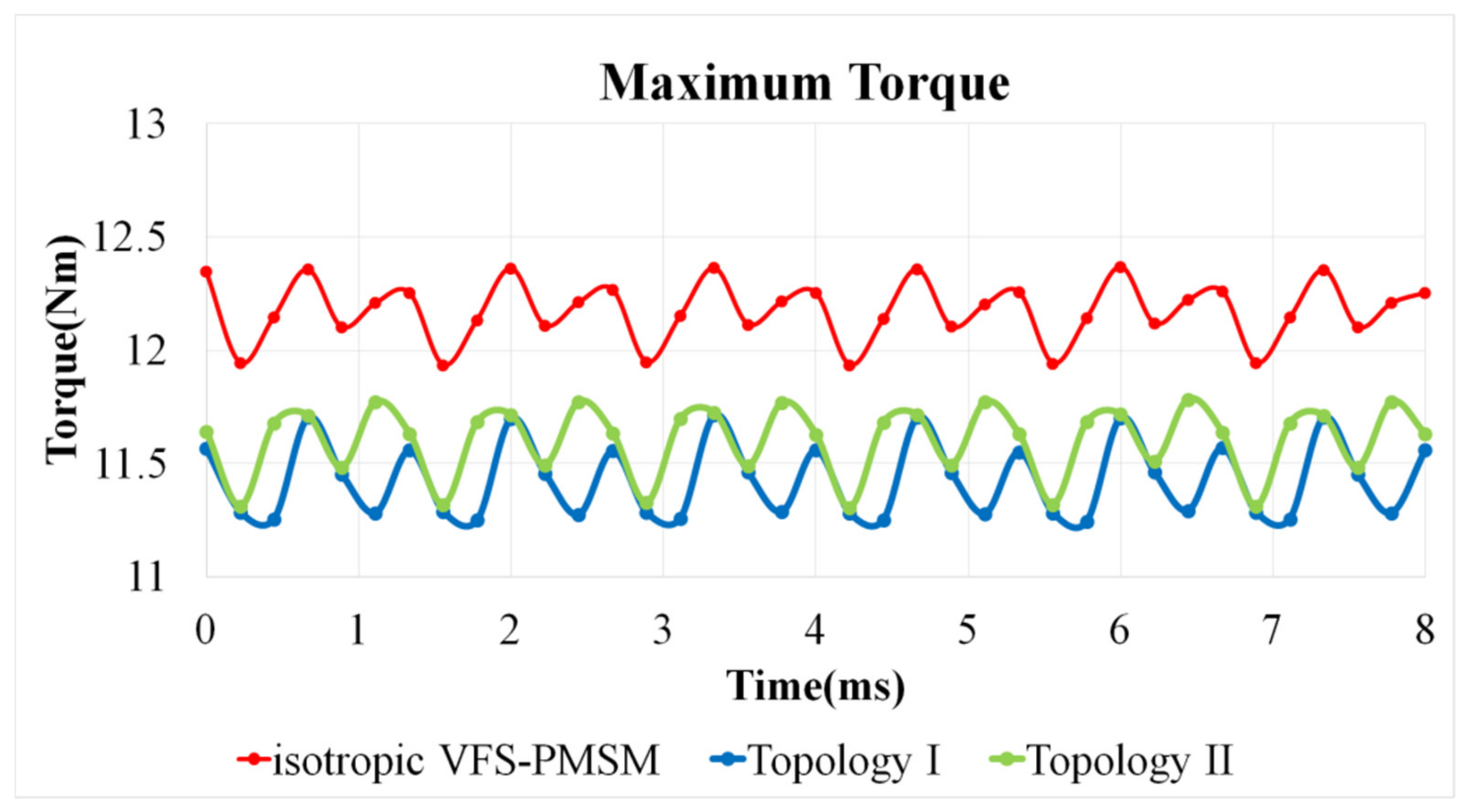
5. Comparison of Anisotropic and Isotropic VFS-PMSMS by Simulation

From the comparison presented in Section 2, it is confirmed that the radial magnetic flux of the LCF magnet has a slight effect on the maximum torque of the VFS-PMSM, while the tangential magnetic flux of the LCF magnet has a great influence on the flux regulation ability; therefore, Topology II has more advantages than Topology I. From the comparison given in Section 4, the conclusion of Section 2 regarding the fact that the tangential magnetic flux of the LCF magnet has a great impact on flux regulation ability is reconfirmed; meanwhile, it is also shown that under the limited size, the spoke-type motor has better key performance such as maximum torque at flux enhancing, flux regulation ability, and torque ripple than other rotor types. Therefore, from the previous comparison, Topology II with the spoke-type rotor is chosen as the final type of design, with the rotor parameters shown in Table 4.
The reason for Lh and LL not being able to be determined in the previous stage discussed in Section 4 is that Lh has a divergent effect on the maximum torque (proportional) and the flux regulation Er (inversely proportional), as shown in Figure 16. Note that LL will vary with Lh and will not be discussed here. To highlight the strengths of the proposed design, two comparisons are made: (a) with the isotropic VFS-PMSM, and (b) with the general types of VFMs, i.e., the series and parallel types. For a fair comparison, the following criteria are considered:
(I)
The comparison under the same maximum torque production;
(II)
The comparison under the same flux regulation ability Er.
Based on the two principles given above, the parameters, Lh and LL, can be determined accordingly referring to the results shown in Figure 16. For example, when comparing with the isotropic VFS-PMSM, a certain Lh (and thus LL) can be chosen from Figure 16 to achieve the same maximum torque as the isotropic VFS-PMSM (Criterion I), and, therefore, the Er of these two motors can be directly compared. For the basis in Criterion II, it is the maximum torque to be compared.
As summarized in Table 5, with a similar Er, the maximum torque of the isotropic VFS-PMSM is 12.12 Nm, and that for the final type of design is 13.47, improved by 11.14%. In this condition, the rotor parameter Lh is 27.5 mm. For a similar maximum torque, the flux regulation ability Er of the final type of design is enhanced by 37.43% when Lh is 25.5 mm. This clearly shows the advantages of the proposed design.
In Figure 16, it can also be observed that the decrease of Er with respect to Lh is faster than the increase of the maximum torque against Lh. Thus, Lh should be carefully chosen for a target Er while gaining the torque as much as possible.
To make a complete comparison, the general series and parallel types of variable flux motors [25,26] are designed for the same HCF magnet usage. The stator and rotor dimensions also remain the same as that for the final type of design. From the simulation results shown in Table 6, when the flux regulation ability is similar, the maximum torque of the final type of design improves by about 7.25% compared to that of the general series type VFM. When the maximum torque is similar, the flux regulation Er of the final type of design is 26.84% higher than that of the general series type VFM. The general parallel type does not consider the potential risk of demagnetization, and thus the simulated maximum torque and Er in Table 7 are better than that of the final type of design. However, if the risk of demagnetization is considered, it will be unstable [26].
The proposed motor is a variable flux motor, and thus it has different torque-speed curves at different air gap flux densities between the two extreme conditions represented by E+ and E, as discussed in Section 2.2. The torque-speed and the power-speed curves of the final type of design with the flux density condition (flux enhancing) to produce the maximum torque are shown in Figure 17a. After switching to a weaker air gap flux density to produce the maximum speed (20,358 rpm), the torque-speed and output power-speed curves are shown in Figure 17b. Finally, the torque-speed curves at various air-gap flux densities can be merged to produce the maximized operating range, as shown in Figure 18. It can be seen that the final type of design has both high torque and high speed with a CPSR of 3.99 (CPSR is defined as the ratio of the maximum speed maintaining the same power as the based speed to the based speed).
From the studies shown above, the proposed anisotropic VFS-PMSM appears to possess more advantages in terms of maximum torque, flux adjustment ability, and the stable LCF magnet operating point compared with the isotropic VFS-PMSM and the conventional series type of VFM. Therefore, these features make the proposed design suitable for EV traction applications.

6. Conclusions

This paper has proposed a variable flux spoke-type permanent magnet synchronous motor using anisotropic AlNiCo as the LCF magnets based on the previously developed isotropic VFS-PMSM. It is confirmed through the experiments that the magnetization direction of the anisotropic AlNiCo can be successfully swiveled with a reduced external magnetizing field/current (a reduction of up to 27% to achieve full magnetization). The spoke-type rotor has been found to be the most suitable configuration for the proposed anisotropic VFS-PMSM. Finally, the comparison with other conventional variable flux motors has shown clear advantages of the proposed design in terms of flux adjustment ability, maximum torque and magnetizing current required. Compared with the general series VFM, the maximum torque of the final type of design improves by about 7.25% and the flux regulation is 26.84% higher. Therefore, it can be concluded that the proposed design is suitable to be applied as an EV traction motor. Further research will be conducted in the future to improve the maximum torque and consider the influence of rotor temperature on motor performance.

Author Contributions

Conceptualization, Y.-H.L. and M.-F.H.; methodology, Y.-H.L.; software, Y.-H.L.; validation, Y.-H.L. and M.-F.H.; formal analysis, Y.-H.L. and M.-F.H.; investigation, Y.-H.L. and M.-F.H.; resources, M.-F.H.; data curation, Y.-H.L.; writing—original draft preparation, Y.-H.L. and M.-F.H.; writing—review and editing, Y.-H.L. and M.-F.H.; visualization, Y.-H.L.; supervision, M.-F.H.; project administration, M.-F.H.; funding acquisition, M.-F.H. All authors have read and agreed to the published version of the manuscript.

Funding

This research was funded by the Ministry of Science and Technology of Taiwan under contract 110-2221-E-006-184-MY2 and the National Space Organization under contract NSPO-S-109343.

Institutional Review Board Statement

Not applicable.

Informed Consent Statement

Not applicable.

Data Availability Statement

Not applicable.

Acknowledgments

The authors would like to thank Y.Z. Weng and W.D. Chen, for their assistance in the experiments. ANSYS is acknowledged for providing Maxwell, the finite element package.

Conflicts of Interest

The authors declare no conflict of interest.

References

  1. Mun, J.; Park, G.; Seo, S.; Kim, D.; Kim, Y.; Jung, S. Design Characteristics of IPMSM With Wide Constant Power Speed Range for EV Traction. IEEE Trans. Magn. 2017, 53, 8105104. [Google Scholar] [CrossRef]
  2. Hwang, M.-H.; Han, J.-H.; Kim, D.-H.; Cha, H.-R. Design and Analysis of Rotor Shapes for IPM Motors in EV Power Traction Platforms. Energies 2018, 11, 2601. [Google Scholar] [CrossRef] [Green Version]
  3. Huynh, T.A.; Hsieh, M.F. Comparative Study of PM-Assisted SynRM and IPMSM on Constant Power Speed Range for EV Applications. IEEE Trans. Magn. 2017, 53, 8211006. [Google Scholar] [CrossRef]
  4. Kim, H.J.; Lee, C.S. Shape Parameters Design for Improving Energy Efficiency of IPM Traction Motor for EV. IEEE Trans. Veh. Technol. 2021, 70, 6662–6673. [Google Scholar] [CrossRef]
  5. Zhang, Y.; Cao, W.; McLoone, S.; Morrow, J. Design and flux-weakening control of an interior permanent magnet synchronous motor for electric vehicles. IEEE Trans. Appl. Supercond. 2016, 26, 0606906. [Google Scholar] [CrossRef] [Green Version]
  6. Fadel, M.; Sepulchre, L.; Pietrzak-David, M. Deep Flux-Weakening Strategy with MTPV for High-Speed IPMSM for Vehicle Application. IFAC-PapersOnLine 2018, 51, 616–621. [Google Scholar] [CrossRef]
  7. Liu, X.; Chen, H.; Zhao, J.; Belahcen, A. Research on the performances and parameters of interior PMSM used for electric vehicles. IEEE Trans. Ind. Electron. 2016, 63, 3533–3545. [Google Scholar] [CrossRef]
  8. Inoue, Y.; Morimoto, S.; Sanada, M. Comparative Study of PMSM Drive Systems Based on Current Control and Direct Torque Control in Flux-Weakening Control Region. IEEE Ind. Appl. 2012, 6, 2382–2389. [Google Scholar] [CrossRef]
  9. Liu, J.; Gong, C.; Han, Z.; Yu, H. IPMSM Model Predictive Control in Flux-Weakening Operation Using an Improved Algorithm. IEEE Trans. Ind. Electron. 2018, 65, 9378–9387. [Google Scholar] [CrossRef]
  10. Leonardi, F.; Matsuo, T.; Li, Y.; Lipo, T.A.; McCleer, P. Design considerations and testresults for a doubly salient PM motor with flux control. In Proceedings of the IAS ’96. Conference Record of the 1996 IEEE Industry Applications Conference Thirty-First IAS Annual Meeting, San Diego, CA, USA, 6–10 October 1996. [Google Scholar]
  11. Finken, T.; Hameyer, K. Study of Hybrid Excited Synchronous Alternators for Automotive Applications Using Coupled FE and Circuit Simulations. IEEE Trans. Magn. 2008, 44, 1598–1601. [Google Scholar] [CrossRef]
  12. Fodorean, D.; Djerdir, A.; Viorel, I.; Miraoui, A. A Double Excited Synchronous Machine for Direct Drive Application—Design and Prototype Tests. IEEE Trans. Energy Convers. 2007, 22, 656–665. [Google Scholar] [CrossRef]
  13. Luo, X.G.; Lipo, T.A. A synchronous/permanent magnet hybrid AC machine. IEEE Trans. Energy Convers. 2000, 15, 203–210. [Google Scholar]
  14. Li, Y.; Lipo, T.A. A doubly salient permanent magnet motor capable of field weakening. In Proceedings of the Power Electronics Specialists Conference, Atlanta, GA, USA, 18–22 June 1995. [Google Scholar]
  15. Kosaka, T.; Kano, Y.; Matsui, N.; Pollock, C. A novel multi-pole permanent magnet synchronous machine with SMC bypass core for magnet flux and SMC field-pole core with toroidal coil for independent field strengthening/weakening. In Proceedings of the 2005 European Conference on Power Electronics and Applications, Dresden, Germany, 11–14 September 2005. [Google Scholar]
  16. Ozawa, I.; Kosaka, T.; Matsui, N. Less rare—Earth Magnet-high power density hybrid excitation motor designed for hybrid electric vehicle. In Proceedings of the 2009 13th European Conference on Power Electronics and Applications, Barcelona, Spain, 8–10 September 2009. [Google Scholar]
  17. Naoe, N.; Fukami, T. Trial production of a hybrid excitation type synchronous machine. In Proceedings of the IEEE Electric Machines and Drives Conference, Cambridge, MA, USA, 17–20 June 2001. [Google Scholar]
  18. Ostovic, V. Memory motors. IEEE Ind. Appl. Mag. 2003, 9, 52–61. [Google Scholar] [CrossRef]
  19. Ostovic, V. Memory motors-a new class of controllable flux PM machines for a true wide speed operation. In Proceedings of the IEEE Industry Applications Conference, Chicago, IL, USA, 30 September–4 October 2001. [Google Scholar]
  20. Limsuwan, N.; Kato, T.; Akatsu, K.; Lorenz, R.D. Design and Evaluation of a Variable-Flux Flux-Intensifying Interior Permanent-Magnet Machine. IEEE Trans. Ind. Appl. 2014, 50, 1015–1024. [Google Scholar] [CrossRef]
  21. Kato, T.; Limsuwan, N.; Yu, C.Y.; Akatsu, K.; Lorenz, R.D. Rare earth reduction using a novel variable magnetomotive force flux-intensified IPM machine. IEEE Trans. Ind. Appl. 2014, 50, 1748–1756. [Google Scholar] [CrossRef]
  22. Zhu, Z.Q.; Hua, H.; Pride, A.; Deodhar, R.; Sasaki, T. Analysis and Reduction of Unipolar Leakage Flux in Series Hybrid Permanent-Magnet Variable Flux Memory Machines. IEEE Trans. Magn. 2017, 53, 2500604. [Google Scholar] [CrossRef]
  23. Zhou, Y.; Chen, Y.; Shen, J. Analysis and improvement of a hybrid permanent-magnet memory motor. IEEE Trans. Energy Convers. 2016, 31, 915–923. [Google Scholar] [CrossRef]
  24. Liu, F.L.; Cheng, L.M.; Wang, M.Q.; Qiao, G.Y.; Zheng, P.; Yang, H. Comparative study of hybrid-PM variable-flux machines with different series PM configurations. AIP Adv. 2019, 9, 125241. [Google Scholar] [CrossRef]
  25. Wang, M.Q.; Yu, B.; Tong, C.D.; Oiao, G.Y.; Liu, F.L.; Yang, S.J.; Zheng, P. Optimization on Magnetization-Regulation Performance of a Variable-Flux Machine with Parallel Permanent Magnets. In Proceedings of the 2020 IEEE 19th Biennial Conference on Electromagnetic Field Computation (CEFC), Pisa, Italy, 16–18 November 2020. [Google Scholar]
  26. Hua, H.; Zhu, Z.Q.; Pride, A.; Deodhar, R.; Sasaki, T. Comparative study of variable flux memory machines with parallel and series hybrid magnets. IEEE Trans. Ind. Appl. 2019, 55, 1408–1419. [Google Scholar] [CrossRef]
  27. Zhang, S.; Zheng, P.; Jahns, T.M.; Cheng, L.; Wang, M.; Sui, Y. A Novel Variable-Flux Permanent-Magnet Synchronous Machine with Quasi-Series Magnet Configuration and Passive Flux Barrier. IEEE Trans. Magn. 2018, 54, 8109705. [Google Scholar] [CrossRef]
  28. Yang, H.; Zheng, H.; Lin, H.; Zhu, Z.Q.; Lyu, S. A Novel Variable Flux Dual-Layer Hybrid Magnet Memory Machine with Bypass Airspace Barriers. In Proceedings of the 2019 IEEE International Electric Machines & Drives Conference (IEMDC), San Diego, CA, USA, 12–15 May 2019. [Google Scholar]
  29. Yang, H.; Zheng, H.; Lyu, S.; Lin, H.; Zhu, Z.Q.; Fu, W. Analysis of Flux Regulation Principle in a Novel Hybrid-Magnet-Circuit Variable Flux Memory Machine. In Proceedings of the 2019 22nd International Conference on Electrical Machines and Systems (ICEMS), Harbin, China, 11–14 August 2019. [Google Scholar]
  30. Yang, H.; Lyu, S.; Lin, H.; Zhu, Z.; Zheng, H.; Wang, T. A Novel Hybrid-Magnetic-Circuit Variable Flux Memory Machine. IEEE Trans. Ind. Electron. 2020, 67, 5258–5268. [Google Scholar] [CrossRef]
  31. Yang, H.; Zheng, H.; Lin, H.Y.; Zhu, Z.Q.; Fu, W.N.; Liu, W.; Lei, J.X.; Lyu, S.K. Investigation of Hybrid-Magnet-Circuit Variable Flux Memory Machines with Different Hybrid Magnet Configurations. IEEE Trans. Ind. Appl. 2020, 57, 340–351. [Google Scholar] [CrossRef]
  32. Lee, Y.H.; Hsieh, M.F.; Chen, P.H. Novel Swiveling Variable Flux Motor with Spoke Type Interior Permanent Magnet. IEEE Access 2022. submitted. [Google Scholar]
Figure 1. B-H curve of LNGT18 (isotropic) and LNGT40 (anisotropic).
Energies 15 03825 g001
Figure 2. (a) Isotropic variable-flux spoke-type permanent magnet synchronous motor (VFS-PMSM), (b) Anisotropic Topology I, and (c) Anisotropic Topology II.
Energies 15 03825 g002
Figure 3. Maximum torque of isotropic VFS-PMSM, Topologies I and II in enhancing state obtained through Maximum Torque per Ampere (isotropic VFS-PMSM = 12.12 Nm, Topology I = 11.42 Nm, Topology II = 11.6 Nm).
Energies 15 03825 g003
Figure 4. Back EMF of (a) isotropic VFS-PMSM, (b) Topology I, and (c) Topology II at enhancing and weakening ( E r   i s o _ V F S   =   8.39 ,   E r   T I   =   3.18   V ,   E r   T I I   =   12.83   V ).
Energies 15 03825 g004aEnergies 15 03825 g004b
Figure 5. Experimental setup. Item “A” is the B-H tracer, item “B” is the magnetizing coil, item “C” is the magnet holder, item “D” is the magnet to be measured, and item “E” is the pickup secondary coil.
Energies 15 03825 g005
Figure 6. (a) Initial magnetization curve on the easy axis, and (b) initial magnetization curve on the hard axis.
Energies 15 03825 g006
Figure 7. Comparison of demagnetization curves by the swiveling method and the general method in easy axis and hard axis.
Energies 15 03825 g007
Figure 8. Rotor configurations with different θh: (a) θh = 36° (spoke-type), (b) θh = 72° (V-type), (c) θh = 108° (V-type), (d) θh = 144° (V-type), and (e) θh = 180° (flat type).
Energies 15 03825 g008aEnergies 15 03825 g008b
Figure 9. Maximum torque and phase advance change with θh.
Energies 15 03825 g009
Figure 10. Er and torque ripple variation with θh.
Energies 15 03825 g010
Figure 11. Schematic diagram of the low coercive force (LCF) magnet arrangement to align with the high coercive force (HCF) magnet.
Energies 15 03825 g011
Figure 12. Maximum torque variation with θh and θL.
Energies 15 03825 g012
Figure 13. Torque ripple variations with θh and θL.
Energies 15 03825 g013
Figure 14. Er variation with θh and θL.
Energies 15 03825 g014
Figure 15. E variation with θh and θL.
Energies 15 03825 g015
Figure 16. Maximum torque and Er of the target type rotor versus Lh.
Energies 15 03825 g016
Figure 17. Torque-speed and output power-speed curve of the final type of design that produces (a) maximum torque; (b) maximum speed.
Energies 15 03825 g017
Figure 18. Complete torque-speed and output power-speed curve of the final type of design.
Energies 15 03825 g018
Table 1. Motor parameters and material properties.
ItemValue
DC-link voltage Udc (V)48
Phase Current (peak) (A)60
Power (kW)2
Rated Speed (rpm)~1500
Outer diameter of stator (mm)160
Outer diameter of rotor (mm)112
Air gap (mm)1
Stack length (mm)36
Winding turns per phase (turns)36
HCF PM gradeN32H
LCF PM grade (isotropic VFS-PMSM/Topology I & II (T_I&II))LNGT18/LNGT40
HCF PM coercivity (kA/m)886
LCF PM (isotropic VFS-PMSM/T_I&II) coercivity (kA/m)100.5/115.7
HCF PM remanence (T)1.146
LCF PM (isotropic VFS-PMSM/T_I&II) remanence (T)0.58/0.866
Stator & rotor steel25CS1500HF
Table 2. Radial and tangential remanence of isotropic VFS-PMSM, Topology I, and Topology II.
Remanence of LCF MagnetsIsotropic VFS-PMSMTopology ITopology II
Radial0.58 T0.895 T0.364 T
Tangential0.58 T0.364 T0.895 T
Table 3. Comparison of external magnetizing field strength required by the swiveling method and the general method in the easy axis and hard axis.
Magnetizing Field Strength Needed in Easy Axis
Swiveling (A)General (B)Decrease Rate (B − A)/B
MS = 100%3.324.5527.0%
MS = 75%2.072.278.8%
MS = 50%1.581.9519.0%
Magnetizing Field Strength Needed in Hard Axis
Swiveling (A)General (B)Decrease Rate (B − A)/B
MS = 100%4.424.552.9%
MS = 75%2.762.956.4%
MS = 50%1.92.1210.4%
Table 4. Rotor parameters of the final type of design.
Parameters (Unit)Value
θh (°)36
θL (°)5.5
Wh (mm)8
WL (mm)6
Table 5. Comparison of maximum torque and Er between final type and isotropic VFS-PMSM.
VFS-PMSM (A)Final Type (B)Difference (%)
((B − A)/A)
Max. Torque (Nm)12.1213.47+11.14%
Er (V)8.398.68+3.46%
VFS-PMSM(A)Final Type (B)Difference (%)
((B − A)/A)
Max. Torque (Nm)12.1212.16+0.33%
Er (V)8.3911.53+37.43%
Table 6. Comparison of maximum torque and Er between final type and series type.
Series (A)Final Type (B)Difference (%)
((B − A)/A)
Max. Torque (Nm)12.8313.76+7.25%
Er (V)7.867.84−0.25%
Series (A)Final Type (B)Difference (%)
((B − A)/A)
Max. Torque (Nm)12.8312.86+0.23%
Er (V)7.869.97+26.84%
Table 7. Comparison of maximum torque and Er between final type and parallel type.
Parallel(A)Final Type (B)Difference (%)
((B − A)/A)
Max. Torque (Nm)12.311.4−7.32%
Er (V)12.7413.01+2.11% 1
Parallel(A)Final Type (B)Difference (%)
((B − A)/A)
Max. Torque (Nm)12.312.53+1.87%
Er (V)12.7410.66−16.33% 1
1 Note demagnetization risk is not considered.
Publisher’s Note: MDPI stays neutral with regard to jurisdictional claims in published maps and institutional affiliations.

