Article

Investigation for Effects of Jet Scale on Flame Stabilization in Scramjet Combustor

State Key Laboratory of High Temperature Gas Dynamics, Institute of Mechanics, Chinese Academy of Sciences, Beijing 100190, China
*
Author to whom correspondence should be addressed.
Energies 2022, 15(10), 3790; https://doi.org/10.3390/en15103790
Submission received: 21 April 2022 / Revised: 15 May 2022 / Accepted: 19 May 2022 / Published: 21 May 2022
(This article belongs to the Special Issue Advancements in High-Speed Combustion and Propulsion Systems)

Abstract

:
Jet scale affects the mixing and combustion of fuel and inflow. With the increase in the scale of scramjet combustors, the study of large-scale jets is particularly significant. The effects of jet scale on flame stability in scramjet combustors were studied by direct-connect combustion experiments. In this paper, the flame distribution characteristics of different jet scales were compared by using similar jet/inflow momentum ratios. The inflow Mach numbers were 2.4 and 3.0, and the total temperature was 1265 K and 1600 K, respectively. The results show that, when the equivalence ratio increases, the combustion intensity increases. Under the condition of same momentum ratio, the increase of jet scale is conducive to fuel injection into the core mainstream, increasing heat release, and the flame stabilization mode will change from cavity stabilization mode to jet-wake stabilization mode. Increasing the distance between jet orifices is not beneficial to combustion, and may even lead to blowoff.

1. Introduction

Hypersonic flight is a research hotspot in many countries. The scramjet is widely studied because of its high specific impulse performance [1]. The scramjet includes four parts: the inlet, the isolator, the combustor, and the nozzle. After deceleration and compression of incoming flow through the inlet, it enters the combustor at supersonic speed and is mixed with fuel for combustion. High-temperature and high-pressure gas is generated and ejected through the nozzle to produce thrust. Two common methods are used to produce higher thrust: expanding the size of a single combustor, or using a large-sized combustor with a multi-module, parallel small-scale combustor. They have their own advantages and disadvantages. Changing the size of the combustor will often adjust the size of the jet hole, which will eventually affect the mixing and combustion of fuel. Smaller-scale combustor combinations produce greater frictional resistance [2].
For supersonic combustion, there is no clear definition of its mechanism. The main reason for this problem is the lack of understanding of turbulent combustion at high Reynolds numbers. In a review of the effects of turbulence on premixed flames at high Reynolds numbers, Driscoll et al. pointed out that turbulent flame speeds tend to follow Damköhler’s predictions [3], and that the measured boundary for flamelet widening occurs where the turbulent diffusivity (based on the Taylor scale) exceeds a certain value, not where the Kolmogorov vortex is located, just inside the laminar flame thickness [4]. During the process of acceleration, the flame shows different stability characteristics with the increase of the Mach number [5], which is similar to the change process of the equivalence ratio [6].
If the controlled molecular mass diffusivity of the mixture exceeds its thermal diffusivity, that is, the Lewis number (Le) of the mixture is less than 1, the mixture whose concentration is close to or exceeds the conventional flammability limit can burn strongly in a turbulent flow. In this case, the associated turbulent flame speed may be several orders of magnitude larger than the corresponding laminar flame speed. Because of the influence of turbulence on combustion, researchers generally believe that there is no scale effect in the combustion phenomenon [7]. More DNS simulations of real burner geometries at real Reynolds numbers are needed to obtain detailed turbulence information, so it is difficult to directly extend from small-scale structures to large-scale structures for supersonic combustors, and typical turbulent jet combustion phenomena are the key elements of supersonic combustion mesoscale problems.
As for the flame structure in supersonic combustion, Driscoll summarized two stable flame structures and the transition structure between them [8], among which the flame is stabilized at the leading edge of the cavity and the wake of fuel injection. According to Sun [9], there are three factors that cause combustion instability. The influence of cavity length to depth ratio on combustion oscillation is mainly realized by the large amount of recirculation in the cavity and the large mass and heat exchange between the cavity shear layer and the core flow. The larger the inclination angle behind the cavity is, the stronger the shock wave is in the cavity, which acts on the shear layer and produces a similar interaction with the boundary layer, then the uplift of the shear layer. The combustion intensity in the cavity increases when the downstream throttling is closer to the cavity and the boundary layer of combustion gradually separates. The interaction between the combustion and the separation boundary layer forms a thermal throat, which causes flame flashback. It is subdivided into three combustion modes: cavity-assisted, jet-wake stabilized combustion, cavity shear-layer-stabilized combustion, and cavity shear-layer/recirculation-stabilized combustion.
With the study of the large-scale combustor, the influence of jet size on mixing and combustion becomes particularly important [10]. In underexpanded jet combustion, a major feature is that many vortices are formed by the collision of detonation slip lines and convect downstream in a region bounded by a supersonic mixing shear layer, which cannot be observed in the non-reactive case. However, combustion cannot be maintained in the mixed shear layer due to the instability of the supersonic shear [11]. The study on different shapes of jet holes shows that the influence on the penetration depth is not more than 5%, but the influence on the mixing area is greater [12], and the greatest influence is the hydraulic diameter. It is found that the scramjet combustor with a larger scale can broaden the flame-rich blowout limit. As the equivalence ratio (ER) increases, the combustion in the small-scale combustor remains in the cavity-stabilized mode, and the flame base moves downstream along the cavity shear layer; however, the combustion in the large-scale combustor gradually transfers from the cavity-stabilized mode to the jet-wake-stabilized mode [13].
It is found that under the same jet/inflow pressure ratio, with the increase of jet diameter, the interaction between the jet and the cavity becomes stronger, and the fluid in the cavity is sucked into the plume by a counter-rotating vortex pair (CVP) [14]. All these works are based on the premise that the pressure ratio of jet/inflow is consistent, and the effect brought by increasing the diameter of the jet is studied, but the total equivalent ratio of fuel will also increase accordingly.
Based on the above background, this paper studied the influence of jet scale on flame stabilization modes through ground direct-connected experiments focusing on the analysis of the effect of jet scale on flow characteristics and the heat release region.

2. Experimental Methods

2.1. Direct-Connected Experiment Setup

The research was carried out at the State Key Laboratory of High Temperature Gas Dynamics, Institute of Mechanics, and Chinese Academy of Sciences. This is an important simulation facility with equipment for the study of supersonic flow and combustion on the ground. It consists of a heater, a Laval nozzle, a test section, and an exhaust. Figure 1 is a schematic diagram of the test. The heater provides a high enthalpy flow by means of burning hydrogen, air, and oxygen; the molar ratio of the product to maintain oxygen is 21%. The total temperature, total pressure, and Mach number simulate flight-state combustion inlet conditions. The repeatability of some experiments is verified, and the results show that the repeatability is very good.
The inflow Mach numbers of the isolator are 2.4 and 3.0, which simulate the flight state of Mach numbers 5.0 and 6.0. Refer to the experimental state in Table 1. These two experimental conditions were chosen for their typical subsonic combustion and supersonic combustion modes of operation. The mass flow is obtained by adding the flow rates of the three gases. Figure 2 shows the sequence diagram of a single test in this paper. The ethylene injection time is 14.5–19.3 s, and the effective time of test is 16.0–19.3 s.

2.2. Test Model and Measuring Methods

The single-side expansion model with a single cavity is used in this paper, as shown in Figure 3. The model consists of a 347 mm-long constant-area isolator, a combustor with a single cavity and a 2° single-side expansion section. The entrance of the model is rectangular with a width of 80 mm and a height of 40 mm. The cavity is 99 mm long, 81 mm long at the bottom, and 18 mm deep. The aft angle of the cavity is 45°. The leading edge of the cavity is 100 mm downstream of the isolator exit. The spark plug is located in the bottom center of the cavity and acts as a model ignitor. The injector is 60.5 mm upstream of the leading edge of the cavity, and the jet of ethylene is perpendicular to the wall. Figure 4 is a top view of three injectors named ϕ1.2 × 6, ϕ1.5 × 6, and ϕ1.7 × 3. The ϕ1.2 × 6 injector has six orifices with a diameter of 1.2 mm and a spacing of 10 mm. Injector ϕ1.5 × 6 has six orifices with a diameter of 1.5 mm and a spacing of 10 mm. Injector ϕ1.7 × 3 has three orifices with a diameter of 1.7 mm and a spacing of 17.5 mm.
Additionally, 63 low-frequency pressure sensors numbered A101–A132 and A201–A232 are installed on the upper wall of the model. Pressure signals are transmitted to the ESP pressure-scanning valve through 1 mm-diameter copper tubes, and then to the low-frequency pressure signal acquisition system, DTC Initium. The ESP pressure-scanning valve has a range of 0–100 psi and a DTC Initium sampling frequency of approximately 331 Hz. Four Kulite XTEL-190 (M) absolute pressure high-frequency pressure sensors with a 7-bar maximum range and a 380 kHz maximum sampling frequency, numbered CH2–CH5, are installed near the cavity and isolator exit. The sampling frequency is 100 kHz in the test. The window 1 ranges are from 382 mm to 567 mm with quartz glass installed on both sides. The window 2 ranges are from 613 mm to 816 mm with quartz glass installed on one side. Window 1 is used for a shadowgraph with a “Phantom V2640” high-speed camera and a Nikon 80–200 mm zoom lens, with a sampling frequency of 15,000 fps and an exposure time of 5 μs. Window 1 and window 2 are used for CH* chemiluminescence with a filtered “Phantom v1612” high-speed camera and Nikon 50 mm prime lens, with a sampling frequency of 15,000 fps and an exposure time of 20 μs. The filter passed through at a wavelength of 430 nm ± 10 nm. The engine thrust was measured by the “OMEGA LC203-1K” load cell with a range of 0–4450 N and a sampling frequency of 1 kHz with an accuracy of 0.15%.

3. Results and Discussion

The experimental fuel equivalence ratio (ER) was designed according to the similarity principle of inflow/jet momentum ratio, as shown in Formula (1). The subscript “jet” represents the jet state, and “flow” represents the inflow state. The specific basis was to ensure that p j e t A j e t was constant for different injectors. According to the above principle, the test conditions in this paper are shown in Table 2.
( m ˙ v ) j e t ( m ˙ v ) f l o w = γ j e t M a j e t 2 P j e t A j e t γ f l o w M a f l o w 2 P f l o w A f l o w

3.1. Flame Stabilization Modes and Characteristics

Due to the pressure fluctuation by the ethylene valve, the stable period of 18.0–19.0s was selected as the research period in this paper, as the pressure was smooth enough. The pressure of 18.0–19.0 s was nondimensionalized by the isolator entrance static pressure p r e f = 70 kPa (Ma = 2.4) or 41 kPa (Ma = 3.0). The Mach number along the combustor was obtained through one-dimensional analysis [15]. The calculated mean and standard deviation of pseudo-color images of CH* chemiluminescence were 18.5–19.0 s, and the shadowgraph was 18.5 s. According to the pressure characteristics along the path, the working conditions can be divided into pure cavity flame stabilization mode, shear layer flame stabilization mode (weak and strong), and jet-wake flame stabilization mode. The following is a brief analysis of the flow and flame characteristics in these conditions.
Figure 5 shows the dimensionless pressure/Mach number along the x axis and the mean pseudo-color image of CH* chemiluminescence at Case 9. The pressure is relatively stable in this test condition, and the pressure rise is relatively small. The dimensionless pressure p / p r e f is slightly higher than 1, and the Mach number near the jet and cavity is slightly higher than 1 and greater than 1, respectively. Because the combustion flame has a long length, the pressure rise caused by combustion was offset by expansion, and the pressure maintains the pressure state of the inlet, which is equivalent to an isobaric combustion state. Corresponding to the CH* pseudo-color image, we found that the flame intensity is weak, and the flame is mainly stabilized in the shear layer, located in the downstream of the cavity. This feature is defined as weak shear layer flame stabilization mode in this paper. Figure 6 showed the shadowgraph, where the depth of injection is relatively low, and the oblique shock wave in the combustor is clear and not greatly affected. It indicates that the flame is in the weak combustion stage of supersonic combustion.
Figure 7 shows the dimensionless pressure/Mach number along the x axis and the mean pseudo-color image of CH* chemiluminescence at Case 11 (1.7D0I0.144). The pressure is relatively stable, and the dimensionless pressure p / p r e f is near 1 in front of the cavity. The highest pressure range is 2–3 times that of the referent pressure; the pressure rises significantly but has not reached the pressure of the normal shock wave. The pressure rise is concentrated in the cavity and extended to the rear edge of the cavity by about 200 mm, where the Mach number is less than 1. Compared with Figure 5, we found that the flame intensity at x = 528 mm is larger than Case 9 (1.7D0I0.099), but the flame area is still stabilized in the shear layer. This feature is defined as strong shear layer flame stabilization mode in this paper. Figure 8 shows the shadowgraph of Case 11 (1.7D0I0.144), where the equivalent ratio is increased, and the ethylene injection depth is higher than Case 9 (1.7D0I0.099). The intensity of the oblique shock wave in the combustor increases with a strong disturbance.
Figure 9 shows the dimensionless pressure/Mach number along the x axis and the mean pseudo-color image of CH* chemiluminescence at Case 5 (1.2D0II0.182). The pressure rise does not exceed 1, and it is basically in the cavity area. In this case, in the expansion section after the cavity, the flame is reignited after the flame is extinguished, which may be caused by the separation and re-attachment of the boundary layer. The reason for this result could be that the flame formed by the main jet is extinguished, and the fuel is entrained by the jet CVP to the cavity and burns. It is possible that the small jet diameter and a weaker jet CVP do not allow for the formation of a shear flame in order to form a stable flame with the main jet. The Mach numbers along the streamline are all greater than 1. The flame is mainly stable in the cavity whose strength is very weak, and this feature is defined as the pure cavity flame stabilization mode in this paper. Figure 10 is the shadowgraph at Case 5 (1.2D0II0.182). Due to the high fluid velocity, the shear layer is compressed in the cavity without expanding outward, which is why the flame in the cavity fails to meet the main jet.
Figure 11 shows the dimensionless averaged pressure/Mach number along the x axis and the mean pseudo-color image of CH* chemiluminescence at Case 13 (1.7D0I0.169). The starting point of the pressure rise is in the isolator, and the magnitude of the pressure rise is very high. The Mach number near the jet and cavity is less than 1, which is typical subsonic combustion. Corresponding to the CH* pseudo-color image, the flame intensity near the jet is very high, and the flame is behind the jet-wake [9,10]. This state is defined as jet-wake flame stabilization mode in this paper. 
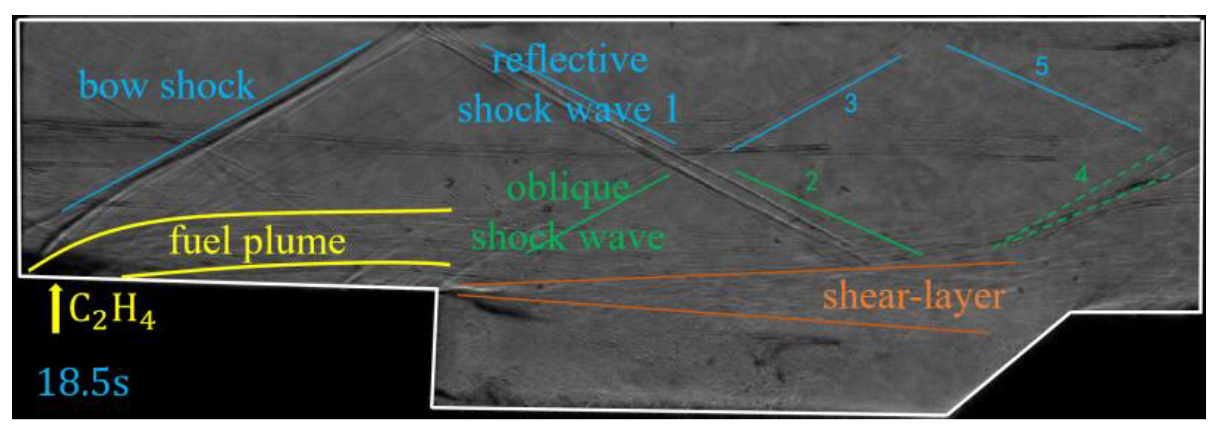
Figure 10 is the shadowgraph of Case 13 (1.7D0I0.169). The depth of injection increases significantly. Due to the strong back pressure generated by combustion heat release, the shock wave train is pushed to the upstream of the jet, as shown the solid blue line in Figure 12.
The jet wake flame stabilization mode is unstable in a certain range. If the shock wave system formed before the main flow decelerates to subsonic speed, but the total temperature and total pressure of flow are not enough to maintain the jet flame stabilization mode, an oscillation mode will occur; with the flame switching from jet wake stabilization to shear layer stabilization, the shock wave also oscillates at same time. The amplitude of flame oscillation varies in different jet scales and equivalence ratios. Figure 13 shows the standard deviation pseudo-color image of CH* chemiluminescence at Case 11 (1.7D0I0.144) and Case 13 (1.7D0I0.169). Figure 14 and Figure 15 show that pressure along the x axis at Case 11 and Case 13 during 18.0–19.0 s. From the trend of color change over time, the pressure fluctuation of Case 11 is small, and the fluctuation area is concentrated in the cavity and the expansion part rear of the cavity. The pressure fluctuation at Case 13 is large, and the fluctuation area is concentrated in the jet and cavity.

3.2. Factors Affecting Flame Stabilization Modes

Many factors will influence the flame stabilization mode, such as air stagnation temperatures [8], equivalence ratio [9], injection distance [16], and fueling schemes [17]. In this paper, ER, jet scale (diameter), and distance between adjacent jet orifices are studied in detail. Figure 16 shows the influence of the ER on the flame stabilization mode. Analyzing the pressure diagram of the combustor for ϕ1.7 × 3 with different ERs in Ma2.4, we found that with the increase of ER, the pressure gradually increases in the combustor, and the pressure rising point moves upstream. The corresponding flame stabilization mode is from blowoff to weak shear layer flame stabilization, then to strong shear layer flame stabilization, and finally to jet-wake flame stabilization. For the same injector, along with the increase of the ER, the jet/inflow momentum ratio and the penetration depth of fuel increases, which forms positive feedback with back pressure caused by heat release, and further improves mixing and combustion of fuel/inflow. The change trend of flame stabilization modes is from weak shear layer to strong shear layer, then to jet-wake stabilization mode with the increase of ER. The change process of flame stabilization between shear layer and jet-wake is abrupt, while the change of internal pressure between shear layer and jet-wake is stable, without abrupt change.
Through the experimental study of injectors with different jet scales (D/H, jet diameter/isolator height), we found that the increase of jet scale will be beneficial to combustion at a large ER, while the increase of jet scale is not conducive to combustion at a small ER.
According to the experiments in this paper, the boundary between large and small ER is whether a strong shear layer can be formed. Figure 17 shows the influence of jet scale with a large ER: 1.5D0I0.141 and 1.2D0 I0.168 form a jet-wake stabilization flame, and 1.2D0I0.150 forms a strong shear layer stabilization flame. Comparing the ER of the three test conditions, it can be found that the ER of 1.5D0I0.141 is less than the ER of 1.2D0I0.168, but the pressure rise of 1.5D0I0.141 is larger, and even causes the change of the flame stabilization mode [14]. A larger recirculation zone in the upstream of the jet caused by a larger jet scale is more conducive to flame stabilization, resulting in the enhancement of combustion heat release. However, for a small ER, the conclusion is the opposite, as shown in Figure 18. The pressure rise in 1.5D0I0.074 is actually smaller than 1.2D0I0.051 for reasons that require further analysis.
Additionally, the distance between adjacent jet orifices also affects the flame stabilization mode, as shown in Figure 19. We found that 1.7D0I0.144 forms a strong shear layer stabilization flame and 1.5D0I0.141 forms a jet-wake stabilization flame. This indicates that the increase of jet orifice spacing is not conducive to heat release, and even offsets the combustion gain brought by the increase of the jet scale. Compared with the working 1.7D0I0.057 and 1.2D0I0.051, when the ER is small, the increase of jet orifice spacing will lead to blowoff.
Figure 20 summarizes flame stabilization modes of different jet scales at different ERs, in which “0” represents blowoff, “1” represents weak shear layer flame stabilization, “2” represents strong shear layer flame stabilization, and “3” represents jet-wake flame stabilization. For the jet scale of 1.2D0, weak shear layer flame stabilization is transformed to strong shear layer flame stabilization when the ER is 0.051–0.075, and a strong shear layer flame stabilization is transformed to jet-wake flame stabilization when the ER is 0.15–0.168. For the jet scale of 1.5D0, the flame stabilization transition point from weak shear layer to strong shear layer is delayed with the ER of 0.074–0.095, and the flame stabilization transition point from strong shear layer to jet-wake is advanced with the ER of 0.117–0.139. For the jet scale of 1.7D0, when the ER is 0.057, the flame in the combustor is blowoff. In the ER of 0.115–0.144, the flame stabilization transition point from weak shear layer to strong shear layer is later than 1.5D0. In the ER of 0.144–0.168, the flame stabilization transition point from strong shear layer to jet-wake is also later than 1.5D0. The above facts show that both jet diameter and jet orifice spacing have an impact on the flame stabilization mode.

3.3. Physical Mechanism of Different Flame Stabilization Modes

Based on the above research results and characteristics of flame stabilization modes, this paper proposes physical mechanisms under different flame stabilization modes, as shown in Figure 21. The fuel distribution of the transverse jet and the cavity will form different modes according to the intensity of the jet flow condition.
There are three regions in the cavity flame stabilization structure: the flow region inside the cavity, the shear layer region, and the jet wake region, respectively. The three are related in that the main function of the flow zone inside the cavity is to exchange material and energy with the shear layer by the recirculation zone of the combustion products. The shear layer zone is the main region of the turbulent flame. The expansion angle of the shear layer is a function of turbulent flame velocity and incoming flow velocity. The jet wake area is based on the transition from the non-premixed flame to the premixed flame. If the flame can be stabilized in the non-premixed area, the jet wake area can self-sustain the flame, and the flame expands to the jet wake area. If not, it will develop into a strong shear layer flame, and part of the flame overlaps with the flame in the shear layer area to form an extended turbulent flame. The jet wake flame is ignited by the shear layer. If the flame is not successfully connected, a weak shear layer flame is formed, and part of the wake fuel enters the shear layer. The flame mode in the cavity formed independently because the turbulence intensity in the shear layer region is higher than the critical condition for flame formation, so flameout occurs.
The jet has an independent mixing zone, and the material exchange with the cavity is carried out through CVP. The influence of the jet size has a great influence on the amount of CVP. The large-scale jet has less generation with the shear layer due to the high penetration depth. The exchange mass is higher, which is also the reason for the higher range of the large-scale blow-out equivalence ratio. However, small-scale jets are more likely to form shear flames because their entire CVP is closer to the shear layer. Therefore, the key to forming a stable flame is the mass exchange between the jet and the shear layer. However, in the process of forming a stable flame, whether it can switch to the jet stable mode is determined by the Da number, where SL is the laminar flame speed, l is the integral length scale, u’ is the fluctuating component of the velocity, and lf is the flame thickness. The turbulent dissipation rate is ε, k is the turbulent kinetic energy, r is the spatial coordinate, and C is a universal constant called the Kolmogorov constant [18].
D a = τ F τ C = S L l u l f
l = 0 f ( r ) d r ; f ( r ) = 1 3 4 C k ( ε r ) 2 3
In the process of combustion flame stabilization, the jet diameter is a more important scale, which affects the evolution process of flame stabilization. It can be seen from Equations (2) and (3) that it mainly affects the integral scale, that is, the scale that affects the vortex structure. The proportional scale of jet diameter and height affects the distribution of flame zones.
The increase of the equivalence ratio means the increase of the jet velocity, which mainly affects three factors. The first is the turbulence intensity of jet mixing. Due to the increase of the convective Mach number, the integral scale of the jet increases, and the Da number increases, and the flame tends to be easily stabilized. The second factor is the spatial distribution of the fuel, which affects the spatial relationship between the jet wake region and the cavity shear layer. The third factor is the change in the total fuel equivalence ratio. The heat release affects the velocity, density, and static temperature of the combustor inlet. These factors ultimately affect the ignition and flame distribution.
For increasing equivalence ratio, the combustion reaction will be intensified, and the heat release area will be enlarged. The non-premixed fuel will also be ignited, but the heat release at this time is not enough to form a precombustion shock wave system in the isolator. Therefore, this state is still a shear layer stabilization flame, but its intensity is significantly higher than that of the weak shear layer stabilization flame, and the heat release area is mainly concentrated in the rear of cavity, so it is defined as a strong shear layer stabilization flame.
When equivalence ratio is further increased, there will be two states according to the jet diameter. One is that the shear layer flame is easy to blow out abruptly [15]. At this time, the fuel at the bottom of the jet wake is brought into the shear layer region of the cavity. The flame stability of the shear layer needs to satisfy the triple flame theory. Another state is that the combustion heat release is enhanced, and a precombustion shock wave is produced by higher back pressure. The large-scale vortex structure exists upstream of the jet, and the penetration depth of fuel injection is increased. A low-speed zone is formed on the side of the jet to stabilize the flame, and the shear layer and cavity provide high-temperature gas for the heat release zone to maintain the reaction.
The effect of the increase of the inlet Mach number is similar to that of the decrease of the equivalence ratio. With the increase of the inlet Mach number, the combustion will change from a strong shear layer stabilization flame to a weak shear layer stabilization flame, or from a weak shear layer stabilization flame to a cavity stabilization flame to blowoff.

4. Conclusions

In this paper, the flow and combustion characteristics of scramjet combustors with different injectors are analyzed by a direct-connected combustion experiment. The main conclusions are as follows.
In the supersonic combustor with the cavity structure, the flame propagation mainly depends on the shear layer between the cavity and the mainstream. The low-intensity combustion mainly forms the shear layer combustion mode, and the high-intensity combustion flame will stabilize in the jet wake area. The flame in the jet wake region is generally unstable, which fluctuates between jet stability and strong shear.
Among the many parameters of the jet, the choice of the diameter is a very important parameter. From the analysis of the experimental results, when the same momentum ratio principle is used to design different jet diameters, the flame will show different stable states. When the equivalence ratio changes, the large diameter jet will change from weak shear to strong shear to jet stability, which is smoother, and thereby easier for small diameters to enter the strong shear mode, but it will lag into the jet stability mode.
The change of flame stability area and intensity is focused on the shear layer, and the supersonic transverse jet is generally unstable, mainly because the flame rises periodically in the jet wake area and separates from the shear layer area, resulting in a lack of fuel in the shear layer area. The shear layer no longer provides the ignition source, and the jet wake flame is partially extinguished, so the pressure drops, and the shock moves downstream. Then, the wake flame extinguishes, and fuel is ignited by the shear layer downstream again. Finally, the combustion wave continues to propagate upstream, completing the full cycle process.
The increase of distance between adjacent jet orifices is not conducive to combustion, and even leads to blowoff. The jet-spreading vortex plays a very important role in flame stabilization, and the exchange of matter and energy between the jet and flame is also significant.

Author Contributions

Funding acquisition, H.G.; Methodology, H.G.; Writing—original draft, Z.L.; Writing—review & editing, H.G. All authors have read and agreed to the published version of the manuscript.

Funding

The research is partially supported by the National Natural Science Foundation of China (Grant No. 11772342).

Institutional Review Board Statement

Not Applicable.

Informed Consent Statement

Not Applicable.

Data Availability Statement

The data that support the findings of this study are available from the corresponding author upon reasonable request.

Acknowledgments

Thanks to Gao Zhanbiao, Li Zhongpeng, and Zhuang Jingheng for their help in the experimental work.

Conflicts of Interest

The authors declare no conflict of interest.

Nomenclature

m ˙ Mass flow (kg/s)
v Velocity (m/s)
γ Specific heat ratio
M a Mach number
p Static pressure (Pa)
A Area (m2)
DaDamköhler Number
U′Velocity fluctuating (m/s)
lfFlame thickness (m)
εTurbulent dissipation rate
kTurbulent kinetic energy
rSpatial coordinate

References

  1. Curran, E.T.; Murthy, S. High-Speed Flight Propulsion Systems; American Institute of Aeronautics and Astronautics: Reston, VA, USA, 1991. [Google Scholar]
  2. Curran, E.T.; Murthy, S. Scramjet Propulsion; American Institute of Aeronautics and Astronautics: Reston, VA, USA, 2000. [Google Scholar]
  3. Driscoll, J.F.; Chen, J.H.; Skiba, A.W.; Carter, C.D.; Hawkes, E.R.; Wang, H.O. Premixed flames subjected to extreme turbulence: Some questions and recent answers. Prog. Energy Combust. Sci. 2020, 76, 100802. [Google Scholar] [CrossRef]
  4. Yuen, F.T.C.; Gülder, Ö.L. Turbulent premixed flame front dynamics and implications for limits of flamelet hypothesis. Proc. Combust. Inst. 2013, 34, 1393–1400. [Google Scholar] [CrossRef]
  5. Meng, Y.; Gu, H.; Zhuang, J.; Sun, W.; Gao, Z.; Lian, H.; Yue, L.; Chang, X. Experimental study of mode transition characteristics of a cavity-based scramjet combustor during acceleration. Aerosp. Sci. Technol. 2019, 93, 105316. [Google Scholar] [CrossRef] [Green Version]
  6. Gu, H.B.; Chen, L.H.; Chang, X.Y. Experimental investigation on the cavity-based scramjet model. Chin. Sci. Bull 2009, 54, 2794–2799. [Google Scholar] [CrossRef] [Green Version]
  7. Yang, S.; Saha, A.; Liang, W.K.; Wu, F.J.; Law, C.K. Extreme role of preferential diffusion in turbulent flame propagation. Combust. Flame 2018, 188, 498–504. [Google Scholar] [CrossRef]
  8. Micka, D.J.; Driscoll, J.F. Combustion characteristics of a dual-mode scramjet combustor with cavity flameholder. Proc. Combust. Inst. 2009, 32, 2397–2404. [Google Scholar] [CrossRef]
  9. Wang, H.B.; Wang, Z.G.; Sun, M.B.; Wu, H.Y. Combustion modes of hydrogen jet combustion in a cavity-based supersonic combustor. Int. J. Hydrog. Energy 2013, 38, 12078–12089. [Google Scholar] [CrossRef]
  10. Sun, M.B.; Zhao, Y.X.; Zhao, G.Y.; Liu, Y. A conceptual design of shock-eliminating clover combustor for large scale scramjet engine. Acta Astronaut. 2017, 130, 34–42. [Google Scholar] [CrossRef]
  11. Su, H.M.; Cai, J.S.; Qu, K.; Pan, S.C. Numerical simulations of inert and reactive highly underexpanded jets. Phys. Fluids 2020, 32, 036104. [Google Scholar]
  12. Li, X.P.; Zhou, R.; Yao, W.; Fan, X.J. Flow characteristic of highly underexpanded jets from various nozzle geometries. Appl. Eng. 2017, 125, 240–253. [Google Scholar] [CrossRef] [Green Version]
  13. Fan, L.I.; Sun, M.; Zhu, J.; Cai, Z.; Wang, H.; Zhang, Y.; Sun, Y. Scaling effects on combustion modes in a single-side expansion kerosene-fueled scramjet combustor. Chin. J. Aeronaut. 2021, 34, 684–690. [Google Scholar]
  14. Zhou, X.H.; Chen, R.Q.; Li, Y.Q.; Teng, J.; You, Y.C. Injection and Mixing Performance in an Elliptical Scramjet Combustor. Tuijin Jishu/J. Propuls. Technol. 2017, 38, 637–645. [Google Scholar]
  15. Wang, Z.P.; Gu, H.B.; Cheng, L.W.; Zhong, F.Q.; Zhang, X.Y. CH* Luminance Distribution Application and a One-Dimensional Model of the Supersonic Combustor Heat Release Quantization. Int. J. Turbo. Jet. Eng. 2019, 36, 45–50. [Google Scholar] [CrossRef]
  16. Wang, Y.; Wang, Z.; Sun, M.; Wang, H. Combustion stabilization modes in a hydrogen-fueled scramjet combustor at high stagnation temperature. Acta Astronaut. 2018, 152, 112–122. [Google Scholar] [CrossRef]
  17. Cai, Z.; Zhu, X.B.; Sun, M.B.; Wang, Z.G. Experiments on flame stabilization in a scramjet combustor with a rear-wall-expansion cavity. Int. J. Hydrog. Energ. 2017, 42, 26752–26761. [Google Scholar] [CrossRef]
  18. Peters, N. Turbulent Combustion; Cambridge University Press: Cambridge, UK; New York, NY, USA, 2000. [Google Scholar]
Figure 1. Schematic diagram of direct-connected test.
Energies 15 03790 g001
Figure 2. Sequence of valves and ignitors in test.
Energies 15 03790 g002
Figure 3. Model in test.
Energies 15 03790 g003
Figure 4. Three injection schemes.
Energies 15 03790 g004
Figure 5. Dimensionless pressure/Mach number along x axis and mean pseudo-color image of CH* chemiluminescence at Case 9 (1.7D0I0.099).
Energies 15 03790 g005
Figure 6. Shadowgraph at Case 9, 1—Reflected shock wave, 2—Intersecting shock waves, 3—Intersecting shock waves, 4—Reflected expansion wave, 5—Reflected shock wave.
Energies 15 03790 g006
Figure 7. Dimensionless pressure/Mach number along x axis and mean pseudo-color image of CH* chemiluminescence at Case 11 (1.7D0I0.144).
Energies 15 03790 g007
Figure 8. Shadowgraph at Case 11 (1.7D0I0.144). 1—Reflected shock wave, 2—Intersecting shock waves, 3—Intersecting shock waves, 4—Reflected expansion wave, 5—Reflected shock wave, 6—Intersecting shock waves, 7—Intersecting expansion wave, 8—Reflected shock wave.
Energies 15 03790 g008
Figure 9. Dimensionless pressure/Mach number along x axis and mean pseudo-color image of CH* chemiluminescence at Case 5 (1.2D0II0.182).
Energies 15 03790 g009
Figure 10. Shadowgraph at Case 5 (1.2D0II0.182), 1—Reflected shock wave, 2—Intersecting shock waves, 3—Intersecting shock waves.
Energies 15 03790 g010
Figure 11. Dimensionless pressure/Mach number along x axis and mean pseudo-color image of CH* chemiluminescence at Case 13 (1.7D0I0.169).
Energies 15 03790 g011
Figure 12. Shadowgraph at Case 13 (1.7D0I0.169), Blue is the shock train and yellow is the jet core boundary.
Energies 15 03790 g012
Figure 13. Standard deviation pseudo-color image of CH* chemiluminescence at Case 11 (1.7D0I0.144) (left) and Case 13 (1.7D0I0.169) (right).
Energies 15 03790 g013
Figure 14. Pressure along x axis at 1.7D0I0.144 during 18.0–19.0 s.
Energies 15 03790 g014
Figure 15. Pressure along x axis at 1.7D0I0.169 during 18.0–19.0 s.
Energies 15 03790 g015
Figure 16. Dimensionless pressure along x axis at different ERs.
Energies 15 03790 g016
Figure 17. Dimensionless pressure along x axis to different injectors at more equivalence ratio.
Energies 15 03790 g017
Figure 18. Dimensionless pressure along x axis to different injectors at less equivalence ratio.
Energies 15 03790 g018
Figure 19. Dimensionless pressure along x axis to different injectors.
Energies 15 03790 g019
Figure 20. Flame stabilization mode for different jet scales at different equivalence ratios.
Energies 15 03790 g020
Figure 21. Mechanism of the flame stabilization mode.
Energies 15 03790 g021
Table 1. The inflow conditions of test.
NumberMaTotal Temperature (K)Total Pressure (MPa)Mass Inflow (kg/s)
I2.412651.06 ± 0.011.40
II3.016001.63 ± 0.011.10
Table 2. Test conditions.
CaseIdentification NumberInjectorInflow ConditionsERJet Scale
11.2D0I0.051ϕ1.2 × 6I0.0511.2D0 1
21.2D0I0.075ϕ1.2 × 6I0.0751.2D0
31.2D0I0.150ϕ1.2 × 6I0.1501.2D0
41.2D0I0.168ϕ1.2 × 6I0.1681.2D0
51.2D0II0.182ϕ1.2 × 6II0.1821.2D0
61.5D0I0.074ϕ1.5 × 6I0.0741.5D0
71.5D0I0.141ϕ1.5 × 6I0.1411.5D0
81.7D0I0.057ϕ1.7 × 3I0.0571.7D0
91.7D0I0.099ϕ1.7 × 3I0.0991.7D0
101.7D0I0.115ϕ1.7 × 3I0.1151.7D0
111.7D0I0.144ϕ1.7 × 3I0.1441.7D0
121.7D0I0.164ϕ1.7 × 3I0.1641.7D0
131.7D0I0.169ϕ1.7 × 3I0.1691.7D0
1 Jet scale is defined as the ratio of jet/inflow hydraulic diameter. D0 is jet scale per mm of jet orifice.
Publisher’s Note: MDPI stays neutral with regard to jurisdictional claims in published maps and institutional affiliations.

