1. Introduction
The NMGs formed by the interconnection technology of multiple microgrids effectively improve the operational performance of an individual MG from the aspect of reliability, flexibility, resilience, power quality, and energy efficiency [
1]. Thus, it could be a promising candidate for the power supply in the feature to relieve the energy crisis.
Usually, NMGs could compatibly contain multiple distributed AC/DC MGs with various voltage levels through the bidirectional interlinking converters (BICs) [
2]. Thus, each MG could directly supply the local loads to their requirements, and the extra power conversion devices can be removed to achieve higher power supply efficiency and flexibility. More importantly, the interconnected MGs can provide mutual support to each other [
3]. Therefore, the large voltage/frequency deviations and overload/light-load of a single MG under serious power imbalance conditions can be avoided. However, the complex physical topology, as well as the diversified DERs will also introduce great challenges to the power management (including the power sharing, voltage/frequency restorations, economic optimization, etc.) of NMGs compared to a single MG system, since the power management issues within and among MGs need to be simultaneously tackled.
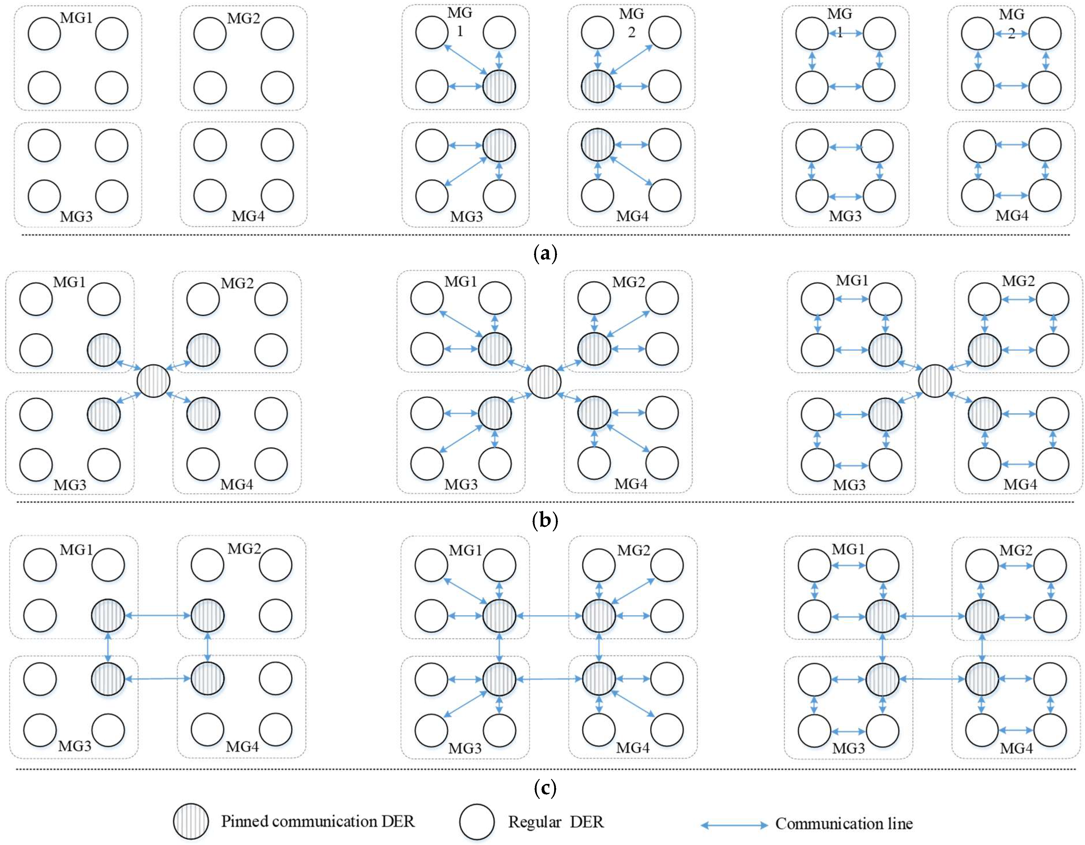
Existing research for NMGs can be classified into fully decentralized control schemes without communication, and centralized and distributed control schemes with communication from the perspective of communication manner [
4,
5]. There are also literatures that use the concept of hierarchical control to describe the power management of NMGs. each layer has different control objectives, but the overall goal realization and the communication manners essentially stay the same [
6]. Specifically, there are also nine types of control schemes with different control combinations within and among MGs, as shown in
Figure 1. For instance, if the centralized control scheme is used among MGs, the centralized, the distributed control schemes, or the fully decentralized control schemes can be used within individual MG [
7]. Similarly, the other combinations can be obtained in the same way.
The fully decentralized control schemes collect the local information instead of communication signals to promote the mutual power interactions [
8,
9], as shown in
Figure 1a. Hence, the merits of high reliability and low cost can be achieved since there is no communication [
10,
11]. It is more suitable for small-scale NMGs, but has the shortcomings of limited functions with only detected local electric signals, poor control accuracy and high local computational burden as the system scale expands [
12].
The centralized control schemes need to employ central terminals to collect, process, and distribute information among converters [
5]. As shown in
Figure 1b, a master central controller among all MGs and several fixed pinned DERs or pinned controllers within individual MG are the necessities to perform the power management within and among MGs [
6]. The centralized control schemes could monitor the entire NMGs, which is convenient for global perception and coordination [
7]. Nevertheless, the power management among MGs would directly fail when the communication terminal fails regardless of which control scheme is adopted within MGs. Therefore, it is sensitive to a single-point communication failure and exhibits the lowest reliability [
13].
With the distributed control schemes, DERs only need to exchange information with their neighbors to gradually realize the system’s consistency with the consensus algorithm [
14]. Compared with centralized control schemes, they could feature enhanced scalability, and reliability [
15]. In [
14,
15,
16,
17,
18,
19], several optimal consensus-based distributed control strategies are presented for MGs to achieve objectives of the voltage/ frequency regulation [
14,
15], active/reactive power sharing [
16,
17], economic operation [
18,
19], and energy-reserve market design [
20], respectively. In [
21,
22], several alternative communication connections of consensus-based distributed control are comparatively analyzed. It is revealed that if one DER links to more neighbors, both the better convergence speed and control accuracy of the entire system can be achieved. Obviously, the communication burden will be greatly increased as well. Moreover, if multiple control objectives, for instance, voltage/ frequency regulation, power sharing, and economic optimization are required simultaneously, the communication system will become very complicated with multiplied data exchange.
Another non-negligible issue of distributed control schemes is the unreliability issues under the pinned terminals outage and communication failures since the fixed pinned DERs or pinned controllers within individual MG are still necessary like that of the centralized control [
23]. Under this circumstance, the MG where this failed terminal is located will completely lose the capability to communicate with others, and deviate from the outside system. The unpredicted communication failure of pinned terminals may even aggravate the power imbalance among MGs and misguide the NMGs into a mal-operation state with stability issues. Thereafter, effective countermeasures to the pinned terminal issues have been investigated by many researchers. In [
24], improved pinning selection strategies based on directed communication networks with considerations of the dynamic performance and optimized convergence time are proposed for NMGs. In [
25], a unification scheme is presented to tackle the pinned master controller (MC) failures in certain MGs as well as the central master controller (CMC) failure. The failed CMC transfers its administration authority to certain MCs and the failed MCs relinquish their control authority to the other imposed MCs in adjacent MGs, to maintain the continuous communications among all the MGs. However, the substitution of previous and newly imposed pinned terminals needs to be well planned in advance. Hence, these methods are essentially still unable to cope with the pinned terminal failures that occur at random times and locations.
Generally, several issues of the existing research remain unsolved (1) Performance and even reliability of NMGs will deteriorate in the event of pinned communication terminal failures, (2) The communication system of NMGs is still intricate with a large amount of communication data, (3) Contradictions exist among multi-objectives, control accuracy, and communication bandwidth.
To address the above issues, this paper proposes a multilevel dynamic master-slave control strategy via two-level dynamic leaders to realize the resilience enhanced power management of NMGs.
Table 1 gives the comparisons of the proposed and the conventional methods, and the main contributions are summarized:
- (1)
The concept of multilevel dynamic leader (MDL) is presented to realize the power management within and among MGs. The dynamic feature enhances the system resilience under the pinned terminal DER outages and communication failure. Also, the multilevel leader overcomes the difference among various DERs and can coordinate the entire NMGs in one control frame.
- (2)
The independent local weight selecting method (LWSM) that implement in each converter is presented to autonomously select the MDL. Thereafter, the communication bus only needs to transmit information to the MDLs. Also, various control objectives including power sharing, and voltage/frequency regulation could be achieved simultaneously by MDLs. As in
Table 1, compared to the data amount with conventional methods, the communication burden could be effectively reduced.
- (3)
The proposed strategy can be extended to NMGs with various topologies, including the series-connected MGs, parallel-connected MGs, and mixed types of the interconnection of MGs with the distribution system, since the MDLs are independent of each other, and the LWSM can be designed according to features of individual MGs and control requirements.
The remainder of this paper is organized as follows. The basic principle of the proposed strategy and resilience enhancement mechanism under random DERs/BICs outage and communication failure are elaborated in
Section 2 and
Section 3, respectively. Feasibility and effectiveness verifications in PSCAD/EMTDC platform are provided in
Section 4. Finally,
Section 5 concludes this paper.
2. Proposed Multilevel Dynamic Master-Slave Control Strategy
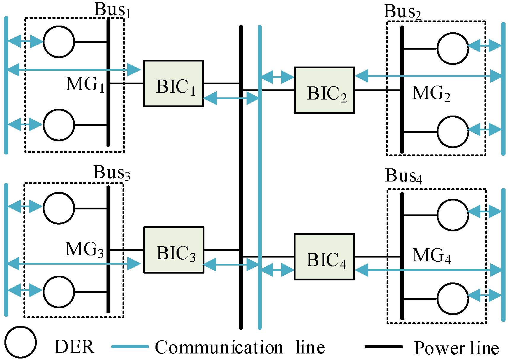
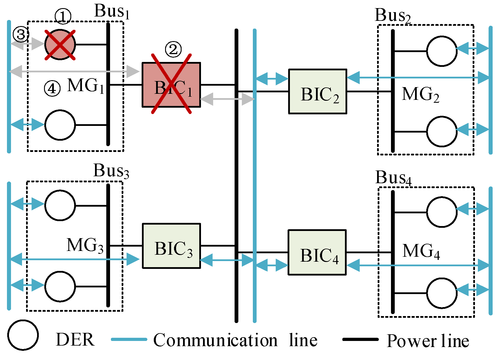
The topology of the NMGs with multiple voltage levels shown in
Figure 2 is taken as an example, which refers to the practical NMGs engineering in Zhejiang province, China [
2,
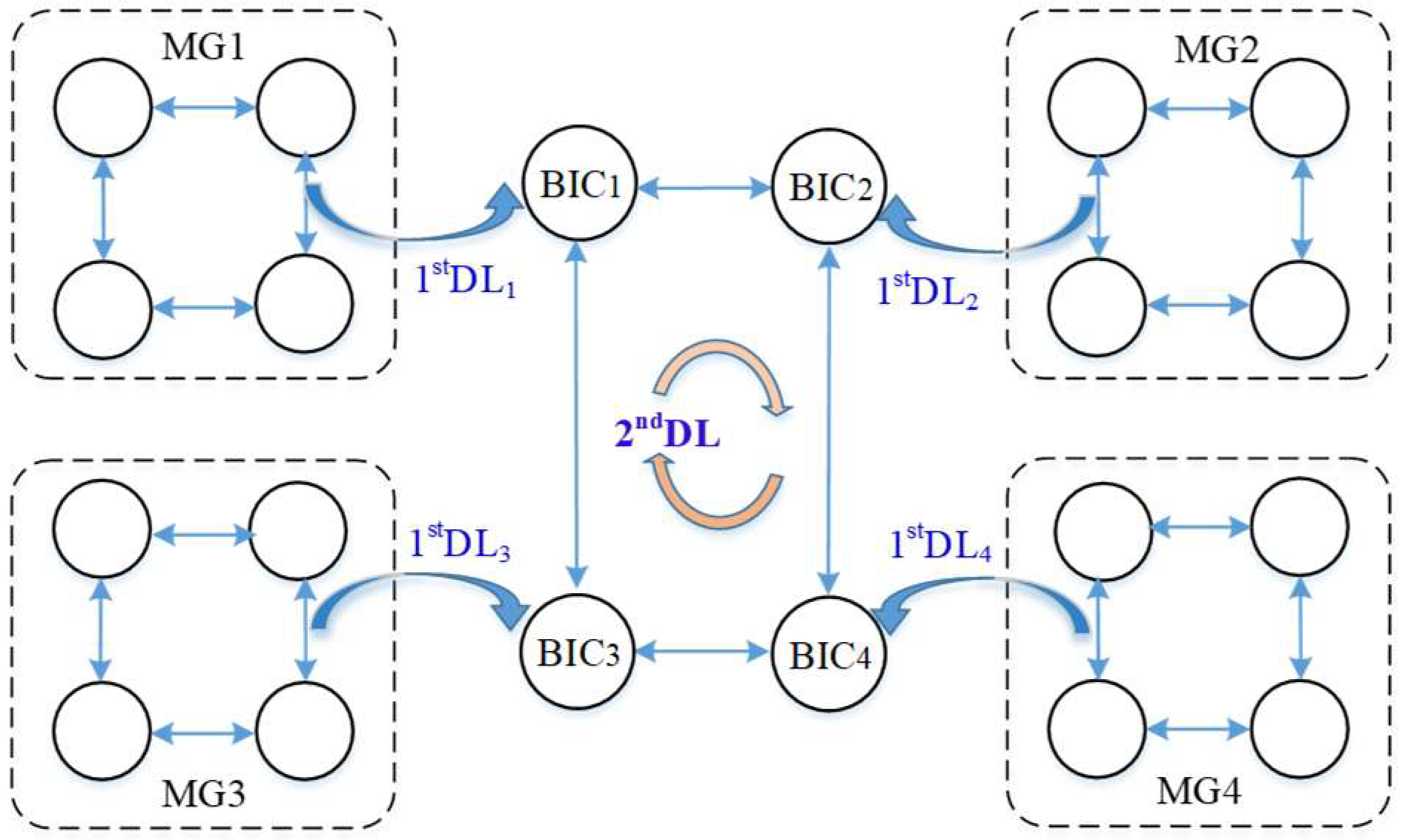
9]. The proposed strategy includes the dynamic master-slave control via the 1st DL within individual MGs and via the 2ndDL among MGs, as is shown in
Figure 3. The implementation flow chart is shown in
Figure 4. First, the standards for the two-level DLs are defined by the control objectives and characteristics of each DER and MG. Then, the 1st DL within each MG is automatically selected by the LWSM, whose information will be shared with other DERs as a unified reference. Third, upon each DER received signals from the communication bus, it will be used as inputs of the secondary controller and generate compensation signals to the primary controller to regulate the real-time output power. Thereafter, the dynamic master-slave control within each individual MG will be achieved.
Subsequently, as for the dynamic master-slave control among MGs, each BIC will collect information on the 1st DL of the MG it is connected with. Then, the 2ndDL will be selected among all the BICs by the LWSM, whose information will be also shared with other BICs through communication as a unified reference as well. After the secondary regulation in BICs by referring to the 2ndDL, the power management of the entire NMGs can be achieved.
Specific principles and implementation of each step will be elaborated as follows.
2.1. Multilevel Dynamic Leader
To realize the dynamic master-slave control within and among MGs with different features, the concept of the 1st DL among all DERs within individual MGs and the 2ndDL among BICs are defined, respectively.
The control objectives include voltage, frequency restorations, power sharing, economic optimization, etc., and the considered inputs to achieve the above objectives contain the capacity of DERs, power generation costs, distance to PCC, key loads proportion, etc. (One objective can have a single input or multiple input combinations). Therefore, to simultaneously realize multi- objectives, the definition of the 1st DL is given in (1).
where subscript i and j denote the number of i-th DER and j-th MG, respectively. F(*) denotes the function of local calculated coordination factor
FXDij of each DER.
FXDij is the normalized in per unit values to promote freely communication among converters with different characteristics. By defining
FXDij with different inputs, multiple control objectives (denoted by the subscript
X) can be achieved simultaneously by taking account of the features of each DER.
FXDmaxj denotes the maximum
FXDij within an individual MG. That is, the DER with the
FXDmaxj would be the 1st DL within this MG. Note that DERs within the same MG should share the same standard for the DL definition. While it could be different among MGs to take respective advantages and features of each MG.
Subsequently, the 2nd DL among BICs is defined, which is essentially based on the information of the 1st DL of the MG the BIC connected with, specific principle is shown in (2).
where
FXBj represents the local calculated coordination factor of BIC.
FBmax denotes the maximum
FXBj among all BICs. That is, the BIC with the
FBmax would be the 2nd DL.
As can be observed in (2), the FXDmaxj of the MG that this BIC is connected to is a significant input of the local calculation of FXBj. That is, the 1st DL will be a representative of this MG to communicate with other MGs through the BIC. Hence, the communication among MGs is actually performed through the dynamic DERs instead of the pinned ones. Besides this, by defining FXBj with different other inputs, features of each MG can also be considered. The MDLs possess three important properties that need to be emphasized. One is that they are not fixed but could be dynamically updated according to the real-time operation. Therefore, the unreliability problems caused by the pinned terminals’ outage and communication failure of conventional methods can be avoided. Second, their definitions could integrate various control objectives together and take account of the features of DERs as well as MGs, which could greatly improve the operation efficiency and flexibility of NMGs. Third, the MDLs establish dynamic connections within and among MGs, but the execution is independent among different levels and does not affect each other. Thus, the “plug and play” advantage can be provided to enhance the scalability of individual MGs or NMGs.
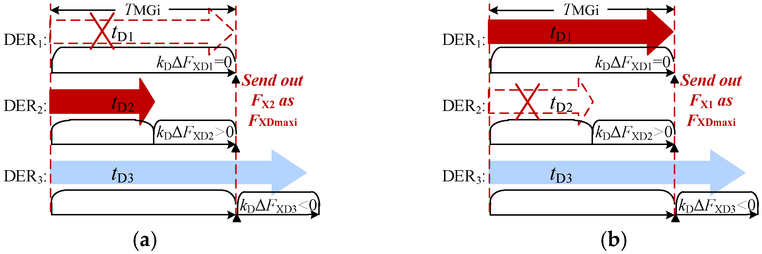
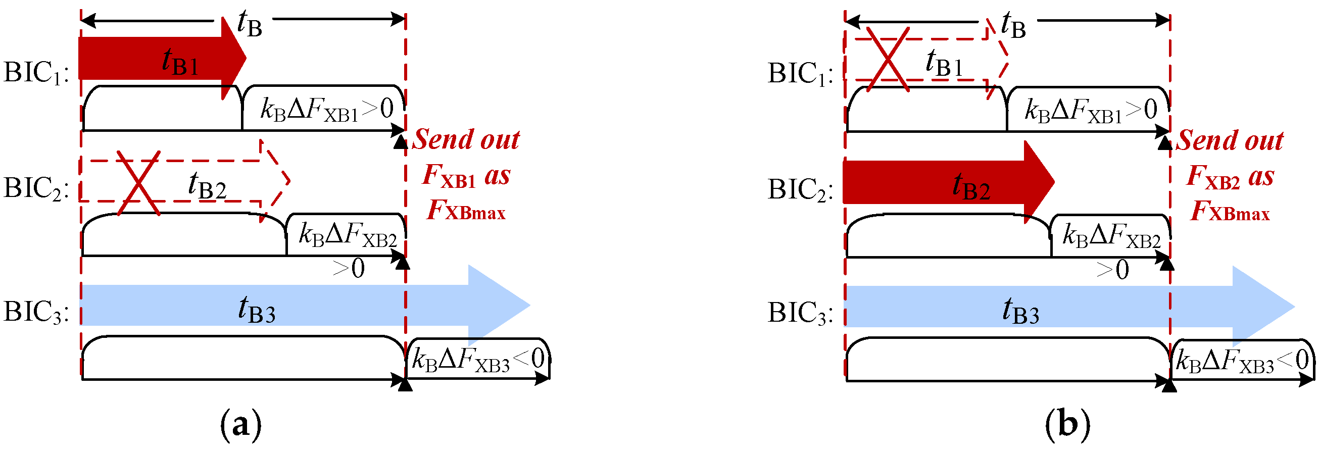
2.2. Local Weight Selecting Method
Upon the definitions of MDLs have been given, it is a great challenge to choose them in NMGs. If all the information is collected to be processed, the communication burden will be tremendous either with the centralized or consensus-algorithm-based methods. Hence, we propose a local weight selecting method (LWSM) for the automatic selection of the MDLs based on our previous work [
26], whose principle is given in (3).
where
tDij is the local calculated waiting time of each DER,
TDj, and
kDj are the rated waiting time and the sensitivity parameter in each MG. DERs within one MG share the same
TDj, and
kDj, but could be different among MGs by their features or control requirements.
tBj is the local calculated waiting time of each BIC,
TBj is their rated waiting time,
kBj is the sensitivity parameter of BIC.
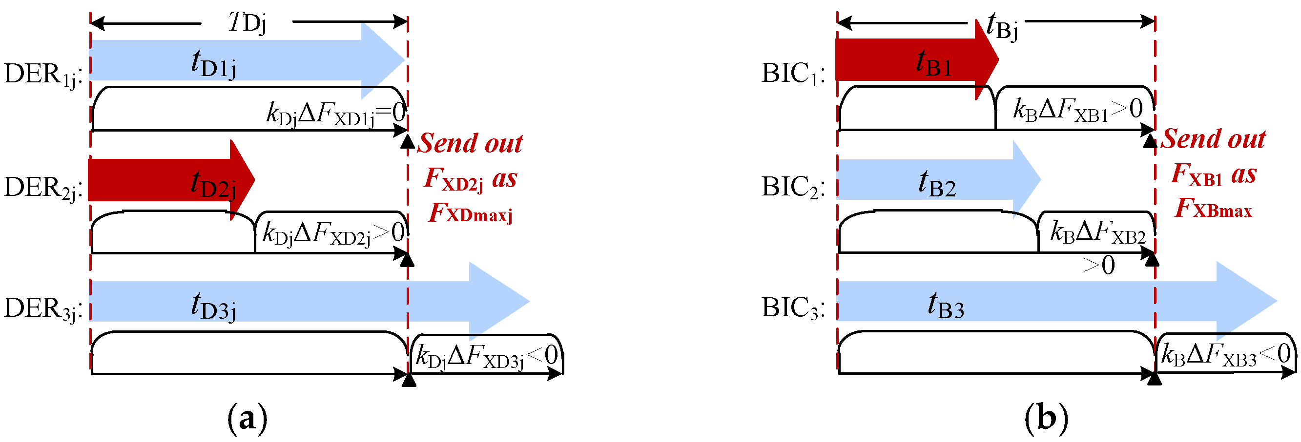
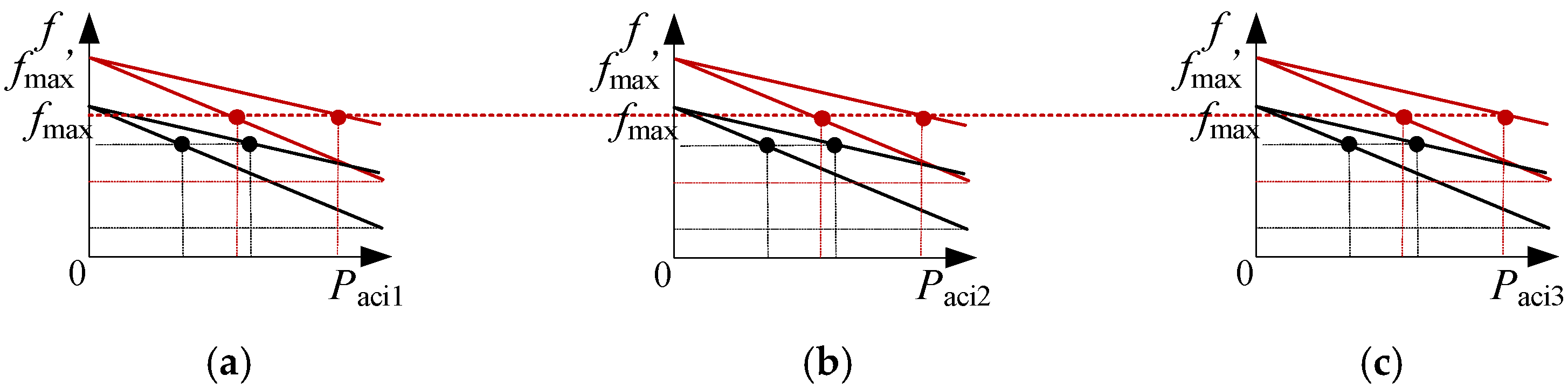
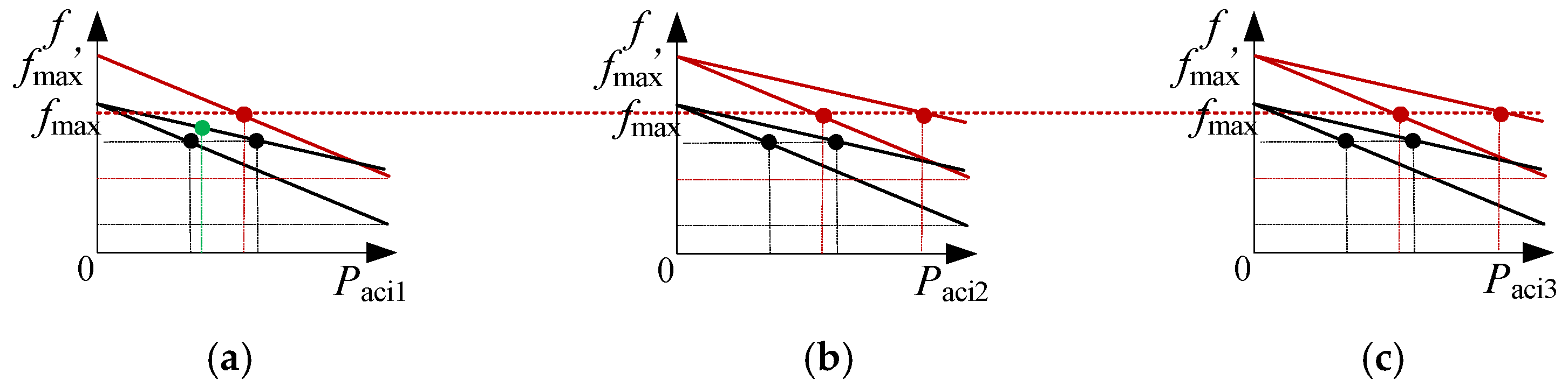
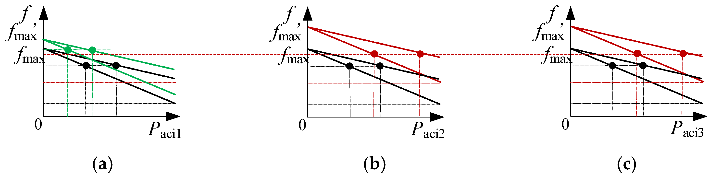
The specific principle of the proposed LWSM is shown in
Figure 5. As can be observed in
Figure 5a, within an individual MG, each DER calculates its own
tDij by (3), the DER with the shortest
tDij will have the highest priority to grasp the communication right and lock it, then send its own information to the other DERs. Thereafter, this DER (represented by red) will automatically become the 1st DL within this MG. Without online comparisons with others, the communication bus only needs to transmit signals of this DL. Therefore, the communication burden can be greatly reduced.
As can be observed in
Figure 5b, LWSM is also applied in BICs for the coordination among MGs, the operation principle is similar to that in DERs, but has an independent selection process in the BIC level. The BIC with the shortest
tBj will be automatically selected as the 2nd DL to guide the other BICs (represented by red) by sharing its information through communication.
It is worth noting that since LWSM is independently performed in each DER/BIC, it could be determined according to features of different MGs and control requirements. Therefore, it possesses great adaptation to the NMGs with various topologies or extensive scale.
2.3. Dynamic Master-Slave Control within Individual MG
The proposed strategy is implemented in the secondary controller of DERs and BICs. Upon DERs receiving commands of 1st DL in an MG, they will perform the secondary control to generate compensation references for the primary control. Then, the actual output of DERs will be changed to finally complete the control objectives carried out by the 1st DL.
The principle of a DER controller is shown in
Figure 6. Where the conventional droop control is applied in the primary controller of DERs for autonomous power sharing, and is ignored here since it has been elaborated on by many literatures.
Principle of the secondary controller is shown in (4),
where
kpij,
X*
Dij, and
XDij are the proportion gain, the rated value, and the detected value, of the i-th DER within the j-th MG, respectively.
GPI(t) is the PI unit to eliminate the error between
FDmaxj received from the communication bus and the local
FDij. Δ
XDij is the control signal generated by secondary control, which is designed to be transferred to the primary droop control.
By the PI tracking in the secondary control and the real-time output power regulation by the primary control, a closed-loop control will be formed to realize the non-error tracking to the signal of the 1st DL. That is, all the DERs within individual MGs will regulate their frequency, voltage, and output power by their unified DL. Afterward, when all DERs’ local coordination factors are equal to each other, as described in (5), the pre-defined control objectives within this MG have been achieved.
2.4. Dynamic Master-Slave Control among MGS
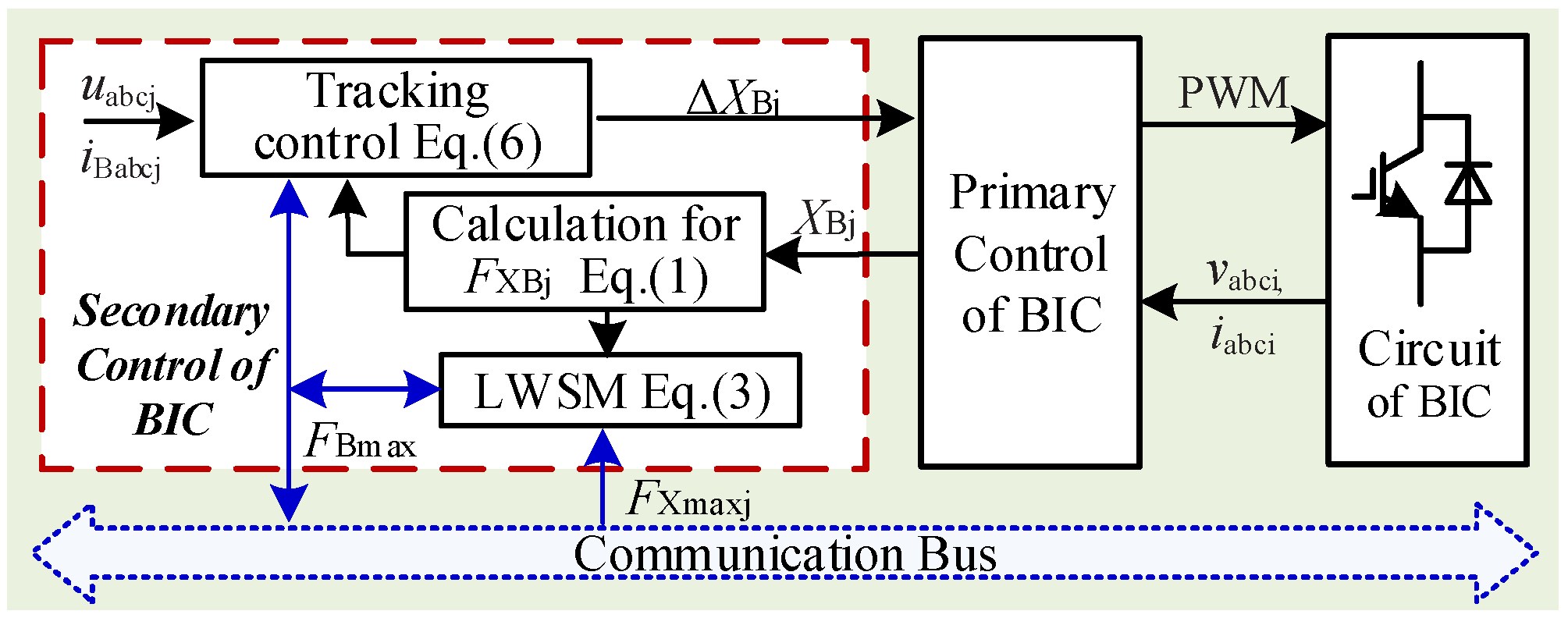
The master-slave control within individual MGs is realized through the coordination of the 1st DL. As shown in
Figure 3, the 1st DL will be a representative of individual MG and transferred to the BIC that is connected to this MG. Each BIC will calculate a local coordination factor. Subsequently, the dynamic master-slave control among MGs can be realized through the coordination of the 2nd DL selected among BICs with the local LWSM.
The control scheme of BIC is shown in
Figure 7, as can be observed, the proposed strategy is implemented in the secondary control with fundamental principles shown in (6), and the conventional normalized droop control elaborated in the existing literature is also applied in the primary controller here [
2].
where
kpBj and
HBj are the proportion gain and the time constant of the j-th BIC, respectively.
GPI(t) is the PI unit to eliminate the error between
FXBmax received from the communication bus and the local
FXBj. Δ
XBj is the control signal generated by secondary control.
Upon a BIC receives the signals FXBmax of the 2nd DL from the communication bus, it will be sent to (6) to calculate the ΔXBj, which is designed to be transferred to the primary controller of BIC to change its real interacted power. Afterward, a closed-loop will be established in BIC to realize the non-error tracking to the 2nd DL. Additionally, HBj in (6) could provide certain inertia, which can be different among BICs by each MG’s characteristics. In this way, if there are fast load fluctuations, the other MGs can be less affected.
Finally, through the local control of each BIC, when there is (7), the local coordination factors
FXBj of all BIC are equal to each other, that is the control objectives among MGs have been achieved. Since the
FXBj is proportional to the 1st LD within individual MGs, equation (8) can be achieved, combined with (5), then (9) can be obtained, which indicates the power management of the entire NMGs has been achieved.
4. Case Study
In this section, case studies are carried out in PSCAD/MTDC to verify the effectiveness of the proposed strategy. The NMGs topology in
Figure 2 which refers to the NMGs in Zhejiang province, China is used to verify that our method could have a promising application in practical engineering. The objectives of proportional power sharing and voltage/frequency restorations are dedicated. Hence,
FXDij =
FPDij =
PDij/
PDijn,
FXBj =
FPBj =
PBj/
PBjn, where
FPDij,
FPBj represent the coordination factor of DER and BIC, respectively.
PDij,
PDijn,
PBj, and
PBjn represent the real and rated output power of the i-th DER in j-th MG, and of the j-th BIC, respectively. Three groups of testing results are elaborated respectively to demonstrate the performance of the control accuracy, the reliability in the events of the DER/BIC outage, and the communication failure. The topology in
Figure 2 is adopted, where three AC MGs (MG
1~3) and one DC MG (MG
4) are contained. Each MG contains two DERs, for instance, DER
11, DER
21 belong to MG
1. DER
12, DER
22 belongs to MG
2, etc. AC bus
1~3 share the rated amplitude of 311 V and rated frequency of 50 Hz. DC bus
4 has a rated amplitude of 800 V. Relevant system parameters are shown in
Table 2.
4.1. Control Accuracy Verification under Load Fluctuations
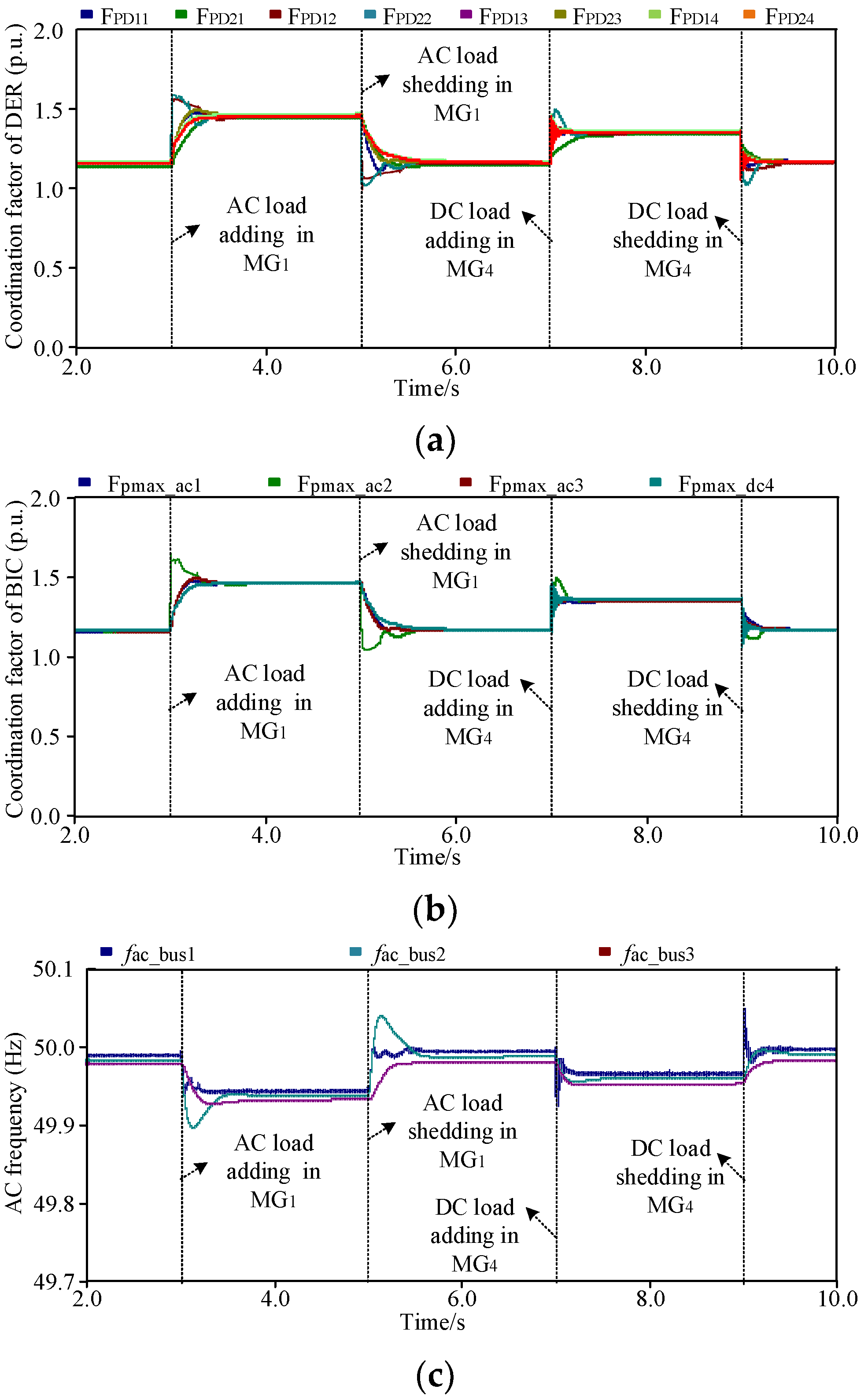
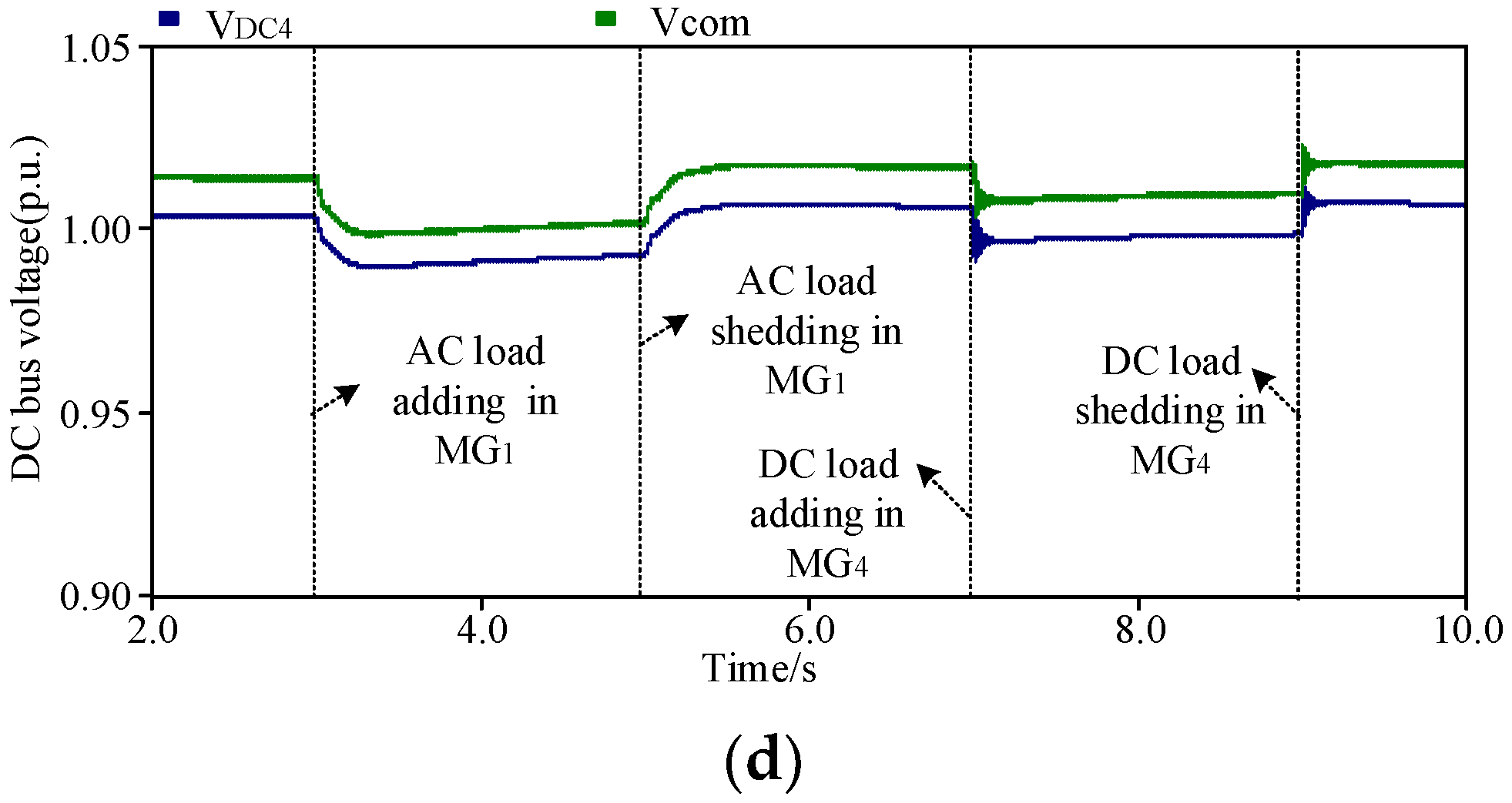
This group of results verifies the control accuracy of the proposed strategy under both regular and fast load fluctuations.
Figure 14 shows the testing results under regular load fluctuations. The overall operating conditions are set as at
T = 3 s and 5 s, there is a load (
S = (32 + 5j) kvar) adding and shedding in AC MG
1, respectively. At
T = 7 s and 9 s, there is a load (
P = 20 kW) adding and shedding in DC MG
4, respectively.
As shown in
Figure 14a, the local coordination factors of all DERs can retain the same value under the random DC/AC load adding and shedding. That is there are always
FPD11 =
FPD21 =
FPD12 =
FPD22 =
FPD13 =
FPD23 =
FPD14 =
FPD24 during the entire load fluctuation process. As shown in
Figure 14b, all the coordination factors of BIC are equal to each other as well. That is there are always
Fpmax_ac1 =
F pmax_ac2 =
F pmax_ac3 =
F pmax_dc4. The results indicate that once there are regular load fluctuations within any MGs, DERs in the other MGs can provide accurate power support through BICs. Finally, accurate power sharing between all the DERs of the entire NMGs can be achieved.
As shown in
Figure 14c,d, due to the local secondary closed-loop control in DERs, both the frequencies and voltages can be restored around their rated values after the regular load fluctuations. Note that the voltage and frequencies only can be restored as close as possible to their rated values, but cannot exactly be equal to them since there are always different line voltage drops and tracking errors, etc.
4.2. Resilience Enhancement Verification under DER and BIC Outage
This group of results verifies the resilience of the proposed strategy under the events of the DER and BIC outage. The overall process is arranged as: at T = 3 s, the outages of DER12 in MG2, and DER13 in MG3 occur simultaneously, at T = 5 s, the DER11 outage occurs in MG1, and at T = 7 s, the BIC1 outage occurs. At T = 7 s and 9 s, there is a load (S = (10 + 2j) kvar) adding and shedding in AC MG2.
As shown in
Figure 15a, when the DER
12 in MG
2 and DER
13 in MG
3 suffer from outages, their output coordination factors become 0, that is, the actual power output is 0. The other DERs in MG
2-3 and other MGs help to share the local loads, and a new system equilibrium will be reached quickly. Moreover, besides DER
12 and DER
13, the factors of all other DERs still remain equal to each other. That is, there is still
FPD11 =
FPD21 =
FPD22 =
FPD23 =
FPD14=
FPD24, except for
FPD12 and
FPD13. As shown in
Figure 15b, the coordination factors of all BICs can also equally reach a new steady-state value,
Fpmax_ac1 =
F pmax_ac2 =
F pmax_ac3 =
F pmax_dc4. At T = 5 s, although the DER
11 outage occurs in MG
1, DER
12 in MG
1 takes the responsibility to interact with the outside system. When the BIC
1 outage occurs at
T = 7 s, the original NMGs are separated into two independent systems, and the coordination factors of all the other DERs in MG
2-4 stay equal during the load fluctuations except for DER
21. It indicates that accurate power sharing can be still achieved.
As shown in
Figure 15c,d, after the DER
12 and DER
13 outages, the frequency/voltage of the entire system can still be consistent. After the BIC1 outage, the frequencies of MG
1 have deviations from that of the rest, but all of them are basically near the rated values.
Hence, this group of results shows that with the proposed strategy, the outage of any converter will only make itself cannot participate in the master-slave control of the NMGs, but without disturbing the control among the others.
4.3. Resilience Enhancement Verification under Communication Failure
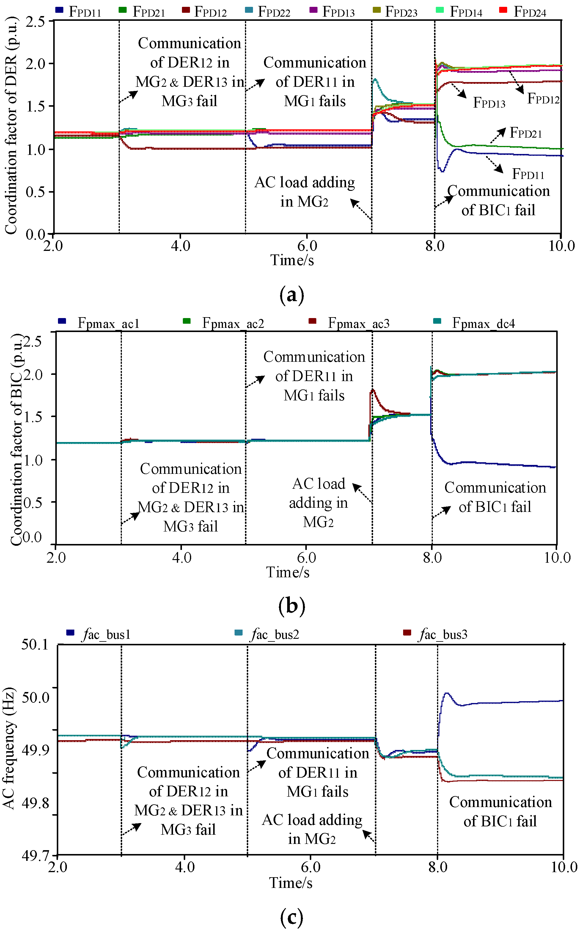
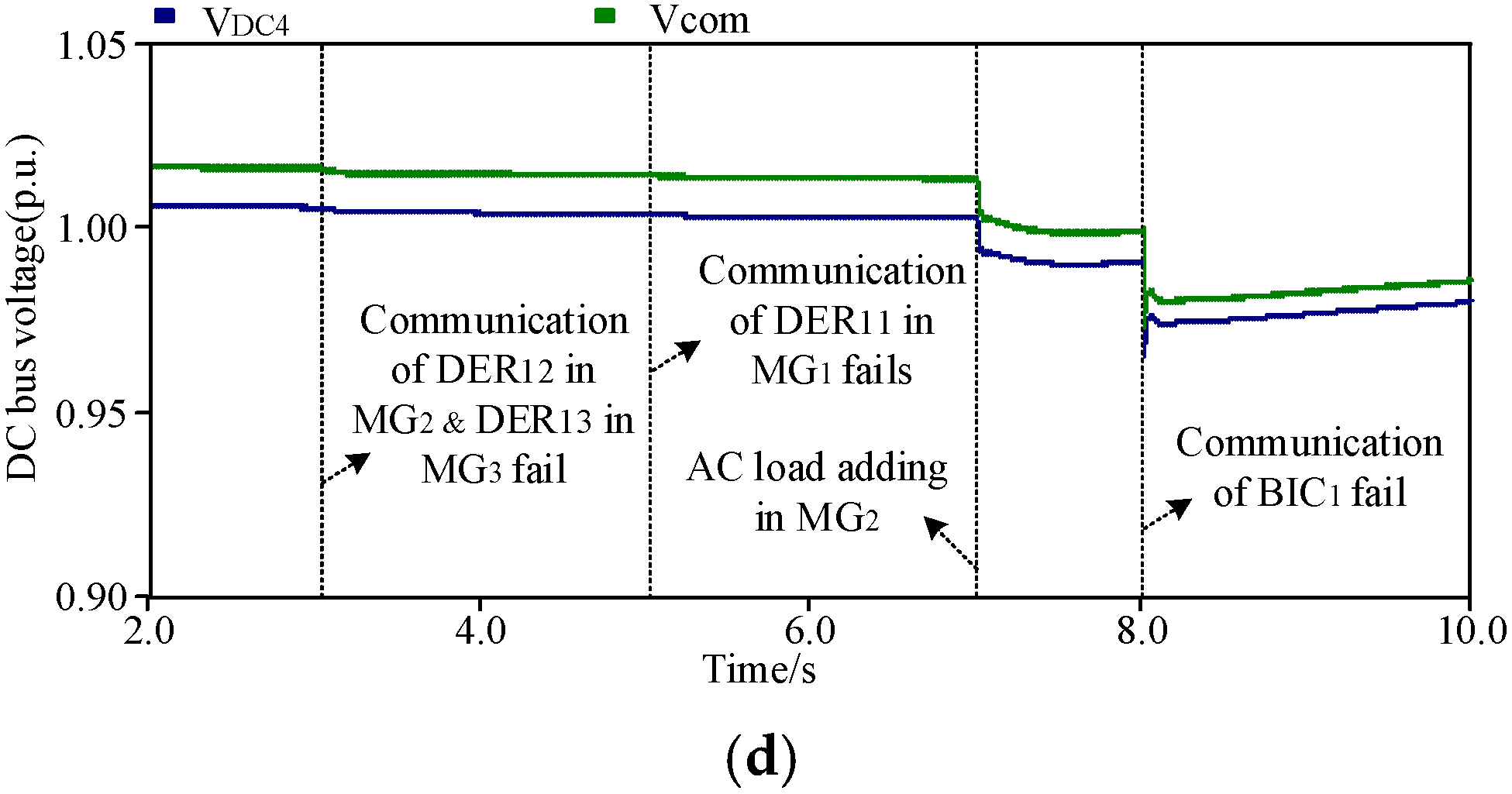
This group of results dedicates to verifying the resilience of the proposed strategy under the DER/BIC communication failure. In the operation process, at T = 3 s, the communication of DER12 in MG2, and DER13 in MG3 fail simultaneously at T = 5 s, the communication function of DER11 in AC MG1 fails, and at T = 7 s, there is a load (S = (10 + 2j) kvar) adding in AC MG2, at T = 8 s, the communication function of BIC1 fails.
As shown in
Figure 16a, when the communication of DER
12 in AC MG
2 and DER
13 in AC MG
3 fails, their output factors cannot be exactly equal to other DERs, but the errors are limited, as denoted by the
FPD12 and
FPD13 in
Figure 16a. This means the output power deviations of DER
12 and DER
13 are small compared with other DERs and can basically follow the load fluctuations. Conditions remain similar when the communication of DER
11 fails at
T = 5 s. Moreover, as shown in
Figure 16b, the output of BIC remains consistent with each other, i.e., the accurate power sharing among MGs is not affected. As in
Figure 16c,d, the voltages/frequencies are all restored near the rated values. These indicate the communication failure of DER does not affect the overall control property.
When the communication of BIC
1 fails at
T = 8 s, MG
1 cannot communicate with the outside system. The coordination factors of DER
11 and DER
21 in MG
1 will deviate from the other DERs, as denoted by
FPD11 and
FPD21 in
Figure 16a. But, the other DERs still maintain good performance. The coordination factor of BIC
1 differs from that of BIC
2-4 since BIC
1 can only rely on droop characteristics to perceive changes in the outside system, as denoted by the
Fpmax_ac1 in
Figure 16b. Hence, the overall condition of MG
1 will have a difference from MG
2-4, which means the communication failure of BIC will only degrade the corresponding MG to keep up with the outside system, but a reliable power supply can be offered. As shown in
Figure 16c, the frequency of AC MG
1 also has slightly deviated from the other AC buses.
Hence, this group of results is consistent with the theoretical analysis in the former section, which indicates that the proposed strategy can still achieve stable performance even under communication failures.
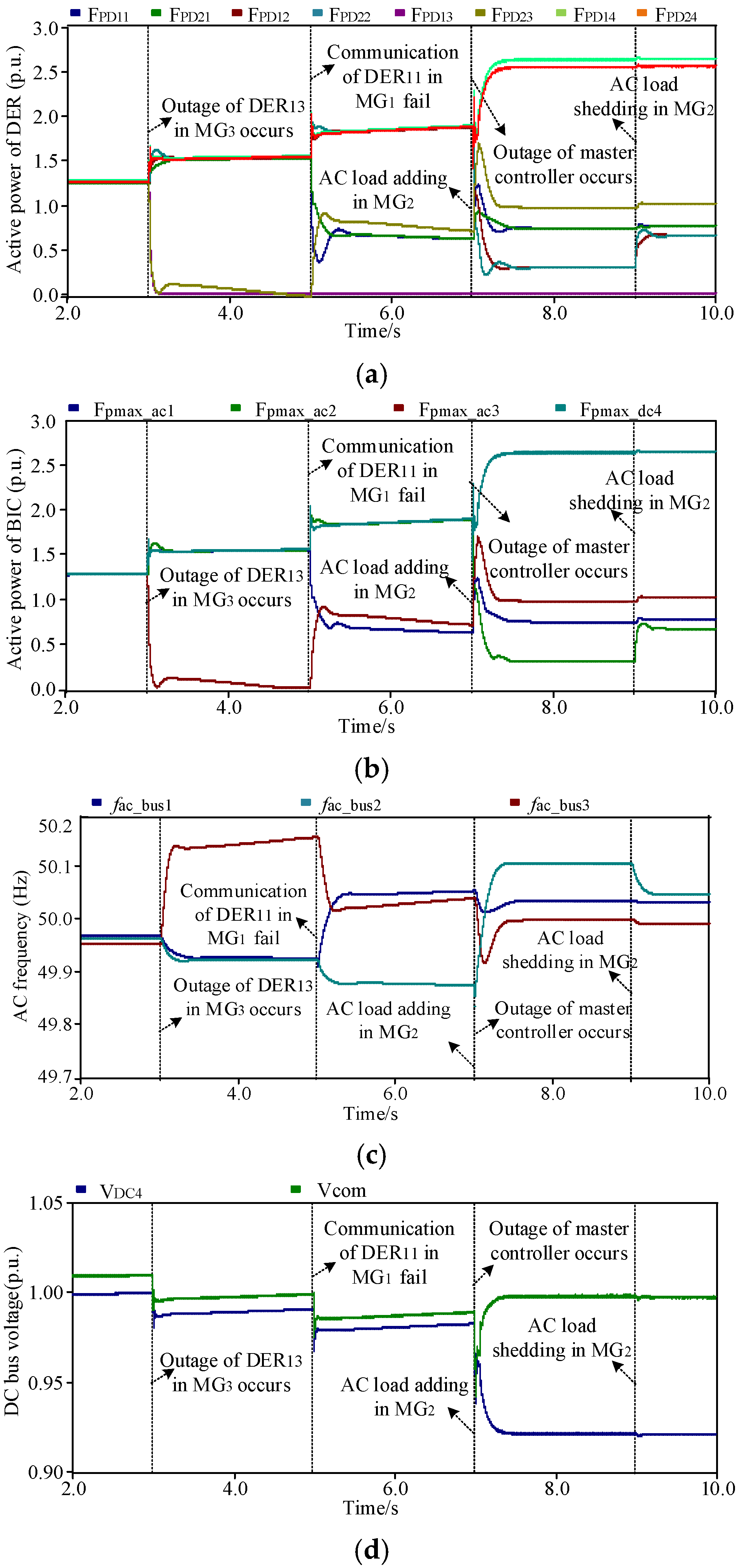
4.4. Comparison with Conventional Methods
To demonstrate the advantages of the proposed strategy, comparative case studies both with conventional centralized and consensus-based distributed control methods are provided. The operation process is at T = 3 s, the outage of DER12 in MG2 occurs, at T = 5 s, the communication function of DER11 in MG1 fails, and at T = 7 s, the master controller outage of the centralized method occurs. At T = 7 s and 9 s, there is a load (S = (10 + 2j) kvar) adding and shedding in AC MG2.
With the centralized control, the DER
1j are set as the pinned terminals within each MG, and a master processing controller among MGs is employed to collect, process, and publish the information to each converter to achieve power management within and among MGs.
Figure 17 shows the results when outages and communication failures of the pinned DERs and the master processing center occur. As can be observed in
Figure 17, when an outage of the pinned DER
13 in MG
3 occurs at
T = 3 s, the accurate power sharing, and effective voltage/frequency regulation functions within MG
3 cannot be realized, and the power interaction with the other MGs also fails directly. When the communication of the pinned DER
11 in MG
1 fails at
T = 5 s, both the power management within MG
1 and with other MGs directly fail. Even worse, when the outage of the master controller occurs at
T = 7 s, the power management of entire NMGs directly fails.
With the consensus-based distributed control, the DERs within each MG need to exchange data with their neighbors, the DER
1j is set as the fixed pinned DERs in each MG to perform a consensus algorithm to achieve power management among MGs.
Figure 18 shows the results when outages and communication failure of the pinned DER within MGs occur. When outage of the pinned DER
13 in MG
3 occurs at
T = 3 s, the power sharing, and voltage/frequency regulation functions within MG
3 can be maintained, but the power interaction with the other MGs will fail directly. When the communication of the pinned DER
11 in MG
1 fails at
T = 5 s, the power management functions within MG
1 still can be realized, but both the power sharing and frequency conditions of MG
1 will deviate from the outside system since the communication among MG
1 and the other MGs has failed.
As can be viewed from the above comparative case studies, with the proposed strategy, advantages in terms of (1) high power sharing, voltage/frequency regulation accuracy; (2) enhanced resilience under the pinned communication DERs outage; (3) enhanced resilience under the pinned DERs communication failure can be effectively verified.


