Article

Study on the Uniformity of Secondary Air of a 660 MW Ultra-Supercritical CFB Boiler

1
Dongfang Boiler Group Co., Ltd., Chengdu 611731, China
2
Key Laboratory of Low-Grade Energy Utilization Technologies and Systems, Ministry of Education of PRC, Chongqing University, Chongqing 400044, China
*
Author to whom correspondence should be addressed.
Energies 2022, 15(10), 3604; https://doi.org/10.3390/en15103604
Submission received: 18 April 2022 / Revised: 5 May 2022 / Accepted: 10 May 2022 / Published: 14 May 2022

Abstract

:
Based on the field test of a 600 MW supercritical circulating-fluidized bed boiler, this paper optimizes the secondary air pipe layout scheme of a 660 MW ultra-supercritical circulating fluidized bed boiler with a similar furnace structure and carried out a numerical simulation on its air distribution uniformity. The secondary air box of the 660 MW ultra-supercritical circulating-fluidized bed boiler adopts a variable section design, and the secondary air branch pipe adopts a separate air inlet mode. The experimental results showed that the oxygen concentration was uniform near the rear wall, but all exhibited a “decrease–increase–decrease” profile along the horizontal line, which indicated that the trajectory of the secondary air jet was first in the shape of bending downward and then upward. To achieve a more uniform secondary air distribution for supercritical CFB boilers, further optimization of the layout of the bellows and branch pipes should be considered. Numerical results showed that the deviation rate of the internal and lower secondary air reached 17%, and there was optimization space for the secondary air branch pipe layout of the boiler. Its uniformity can be increased by adding valves and other measures. The velocity deviation of the secondary air of the 660 MW ultra-supercritical circulating-fluidized bed boiler can be within 3% by means of separate air supply and pipe diameter change, and better uniform air supply can be achieved to reduce the speed deviation by adding valves and adjusting the combustion.

1. Introduction

Circulating-fluidized bed (CFB) combustion technology is a clean and efficient combustion technology that has been widely used in power and chemical industries in the last forty years, and it has been developed towards large-scale, high-parameter, and low-pollutant emissions [1,2,3,4,5]. In China, where the energy structure is dominated by coal and especially with the continuous improvement of national requirements for energy conservation and environmental protection, supercritical CFB boilers have developed rapidly in recent years and have been widely used. By October 2020, 46 supercritical CFB boilers have been put into operation in China (including 350–660 MW), and the total evaporation capacity is several times higher than that of supercritical CFB boilers in other countries in the world. The superheated steam temperature and reheated steam temperature of the 660 MW ultra-supercritical CFB boiler (with a superheated steam pressure of 29.4 MPa) under development will reach 605 °C and 623 °C, respectively, and will become the CFB boiler with the highest steam parameters in the world after being put into operation [6,7]. In the process of further improving the parameters of CFB boilers, especially under the background of the continuous improvement of national requirements for energy conservation and emission reduction of coal-fired units in recent years, there are still technical problems, including the combustion uniformity in furnaces, that need to be deeply studied and continuously optimized for large-scale CFB boilers [6,7,8]. For the existing supercritical CFB boilers, the furnace width can usually reach 30 m. To achieve uniform air distribution and further achieve uniform combustion, 30~50 nozzles are set in different positions along the furnace height direction to introduce secondary air to control the furnace temperature and atmosphere effectively and further consider the requirements of pollutant emissions [9]. To control the generation of NOx, the secondary air is often employed, which makes the bottom region of the furnace deviate from the stoichiometric combustion. In addition, as an important means of combustion adjustment, the high-speed SA jet can intensify mixing of the bed materials, which is particularly conducive to the burnout of fuel. Meanwhile, in terms of furnace width and depth, the penetration of secondary air must be considered when determining the furnace size of large CFB boilers. Generally, the size along the incident direction of the secondary air does not exceed 10 m. Therefore, for large-scale CFB boilers with capacities of 600 MW and above, the structure of double lower furnace can be adopted at the lower part of the furnace to facilitate the penetration of the secondary air [10,11].
For CFB boilers, the layout and design of secondary air ducts need to consider the influence on the gas–solid two-phase flow, combustion, and heat transfer characteristics in the furnace [12,13,14,15,16]. Among them, gas–solid flow is the basis, and there was some research about the incident depth of secondary air and the effect of secondary air on the particle concentration in the furnace based on tests or calculations [17,18,19,20,21]. However, few reports were about the uniformity of the layout of secondary air bellows and branch pipes of actual supercritical CFB boilers. Only Zhou et al. [22] studied the secondary air box and branch pipe layout of a 600 MW CFB boiler through actual measurement and numerical calculation and put forward some suggestions.
At present, the research and development of the ultra-supercritical CFB boiler has been widely carried out in China. Based on the 600 MW supercritical CFB boiler that has been put into operation, the furnace size of the 660 MW ultra-supercritical CFB boiler is slightly enlarged, and it needs to meet the latest pollutant emission requirements. This puts forward higher requirements for the setting of the secondary air and the layout of the secondary air pipeline. However, within the scope of the authors’ understanding, there was little literature regarding the simulation in the regions of the second air jet of a large-scale boiler, which could assess the influence of second air intuitively and accurately. The layout of the secondary air box and branch pipe of a 660 MW ultra-supercritical CFB boiler is close to that of the 600 MW supercritical CFB boiler, which provides a reference for further improving the design of the secondary air layout. Therefore, based on the field test of the secondary air oxygen distribution in the 600 MW supercritical CFB boiler, the secondary air box and branch pipe of the 660 MW ultra-supercritical CFB boiler were taken as the object in this paper, the influence of the existing design on the secondary air uniformity through numerical calculation was investigated, and some useful suggestions were put forward.

2. Test and Result Analysis of Actual Boiler

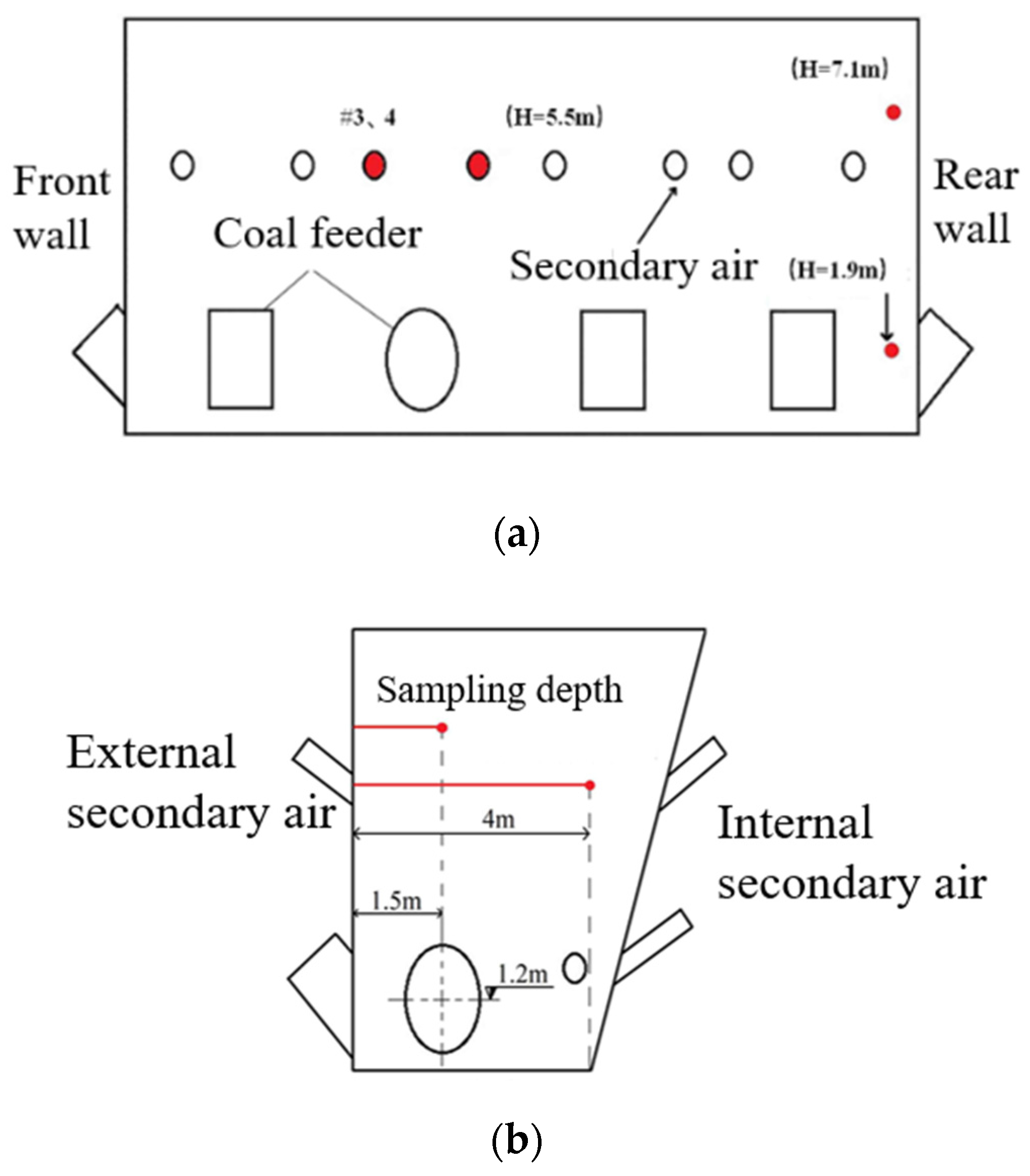
2.1. Test Object and Method

To take into account the penetration of the secondary air in the 600 MW supercritical CFB boiler, the lower furnace adopts double lower furnace structure, forming two air distribution plates, namely a single-furnace, double-air distribution plate. The left and right legs are symmetrically arranged on the intermediate water-cooled partition wall, and the structure of one side of the furnace is shown in Figure 1. The secondary air is arranged in the upper and lower layers, respectively. The external secondary air is arranged in a single layer, 5.5 m away from the air distribution plate, and the internal secondary air is arranged in two layers, 5.5 m and 2.5 m away from the air distribution plate.
The hot secondary air heated by the air preheater leads from the rear of the furnace to the hot secondary air main pipe, and the hot secondary air main pipe is divided into two paths, corresponding to the internal and external secondary air, respectively. There are twenty-one secondary air ducts on one side of the furnace, including eight lateral secondary air ducts, five medial upper secondary air ducts, and eight medial lower secondary air ducts. The secondary air in the internal lower secondary air branch 1 is drawn from branch 2, as shown in Figure 2. To obtain the distribution characteristics of the secondary air jet in the furnace during the operation of the actual furnace and provide a reference for the arrangement of the secondary air branch pipes in the 660 MW ultra-supercritical CFB boilers, flow measurement devices and flue-gas-sampling points were installed on the secondary air pipes on the external walls of #3 and #4 on both sides of the 600 MW supercritical CFB boiler, and two upper and lower flue-gas-sampling points and pressure measuring points were installed near the rear wall on both sides of the wall. The upper and lower measuring points were 1.9 m and 7.1 m away from the air distribution plate, respectively. The horizontal distance from the secondary air outlet outside #8 was about 2.1 m, and the distance from the rear wall was about 0.50 m. The specific arrangement of the measuring points is shown in Figure 3. The maximum depth of the flue-gas-sampling was 4 m, which can cover the size of the whole air distribution plate and the range of the elevation above 70%; thus, it can be considered to reflect the distribution trend of the flue gas composition in this section. Sampling system settings and methods were based on previous research results [23,24].
According to the measurement results of the secondary air outlets on both sides of the furnace, as well as the measurement results at the corner of the rear wall, and combined with the cooling down of the nozzle speed of each secondary air outlet, the relationship between the secondary air volume at outlets and the oxygen distribution on the horizontal axis of the nozzle can be obtained. Combined with the air volume measurement data of each secondary air outlet in the thermal state, the oxygen distribution on the furnace section where the axis of the secondary air outlet is located can be obtained. The test conditions are shown in Table 1.

2.2. Analysis of Test Results of Actual Furnace

Figure 4 shows the oxygen distribution in flue gas of four secondary air nozzles on both sides of the wall along the horizontal axis of the nozzle under 97% and 60% boiler load. It can be seen that the oxygen distribution trend of the four secondary air nozzles on the horizontal axis of the furnace was basically the same under different loads. The test results basically represented the distribution of oxygen in the secondary air jet in the furnace. Meanwhile, it can be found that under different boiler loads, the oxygen concentration in the furnace presented a trend of decreasing–increasing–decreasing, which indicates that the trajectory of the secondary air jet was in the shape of first bending downward and then up warping, as shown in Figure 5. The results were also consistent with the existing literature [25].
By analyzing the data in Figure 4, it is found that at the distance of 4 m from the side wall nozzle, close to the position of the internal furnace wall, the oxygen content at 97% boiler load was above 6%, which was higher than the oxygen concentration at the furnace outlet. When the boiler runs close to the rated load, the dense phase region was usually under a reduced atmosphere, and the oxygen content at the furnace outlet was usually controlled at around 3%, indicating that at this load, the secondary air jet can cover the whole cross section of the furnace, and there was no oxygen deficiency in the central area of the furnace. It can also be seen from Figure 4 that the oxygen content of the flue gas inside the furnace at 60% load was less than 4%. This is lower than the furnace outlet oxygen (about 5~6%) of general CFB boilers under 60% load operation. It indicates that at low loads, the reduction of secondary air flow was too much, and it was difficult for the secondary air jet to reach the region of 4 m, further resulting in a low-oxygen content in this region at low loads, and hypoxia may exist in extreme cases.
In the experiment, the secondary air is injected into the furnace at 30° to the horizontal direction, and the corresponding jet trajectory was similar to a parabola, as shown in Figure 5. The particle concentration at the corresponding height can be calculated through the pressure measurement of two corner-measuring points, and the particle concentration near the secondary air jet was about 0.018. Relevant contents can be found in our previous work [26]. Further calculations showed that the depth of the horizontal jet under 97% and 60% BMCR conditions was 2.30 m and 2.10 m, respectively.
Figure 6 shows the oxygen distribution value of the furnace section where the axis of the upper secondary air nozzle was located under 97% load based on the measured oxygen distribution on the four secondary air jet axes of the 600 MW supercritical CFB boiler, the horizontal diffusion law of the secondary air measured at the four flue gas composition-measuring points behind the boiler, and the outlet velocity of each nozzle measured during the cold-leveling test of the secondary air nozzle. It is found that in the upward projection area of the air distribution plate, the influence range of the external secondary air was large, and at least two-thirds of the horizontal area of the furnace was covered at 97% boiler load. In areas with large secondary air intervals, such as between 1# and 2# vents, between 5# and 6#, and between 7# and 8# secondary air vents, there were areas with low-oxygen content. There were also some low-oxygen areas near the corner of the internal wall and between the internal 3# and internal 4# secondary air vents. In addition, there were some local oxygen deficient areas (#1 and 8# branch pipe coverage) along the front and rear sides of the furnace depth. Therefore, for the 660 MW ultra-supercritical CFB boiler with a similar furnace structure and air distribution, further optimizing the layout of the bellows and branch pipes to achieve a more uniform secondary air distribution can be considered.
The resistance of the flue gas and air duct of the utility boiler can be calculated by the following formula [27]:
Δ P l = ζ × ρ ω 2 2
Δ P f = λ × L d × ρ ω 2 2
where ζ and λ are resistance coefficients, ρ is the density of the fluid, ω is the fluid velocity, and L and d are the length and equivalent diameter of the air duct, respectively. To realize the further uniformity of the secondary air, it can be carried out from the aspects of local structure and pipe diameter of the air duct.

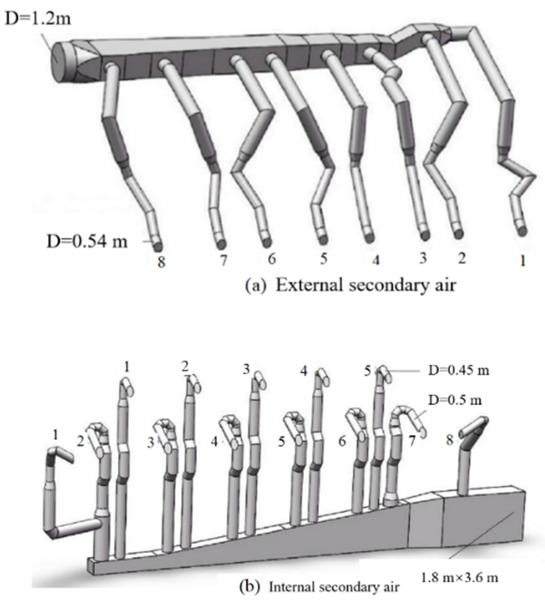
3. Numerical Simulation of Ultra-Supercritical CFB Secondary Air Duct

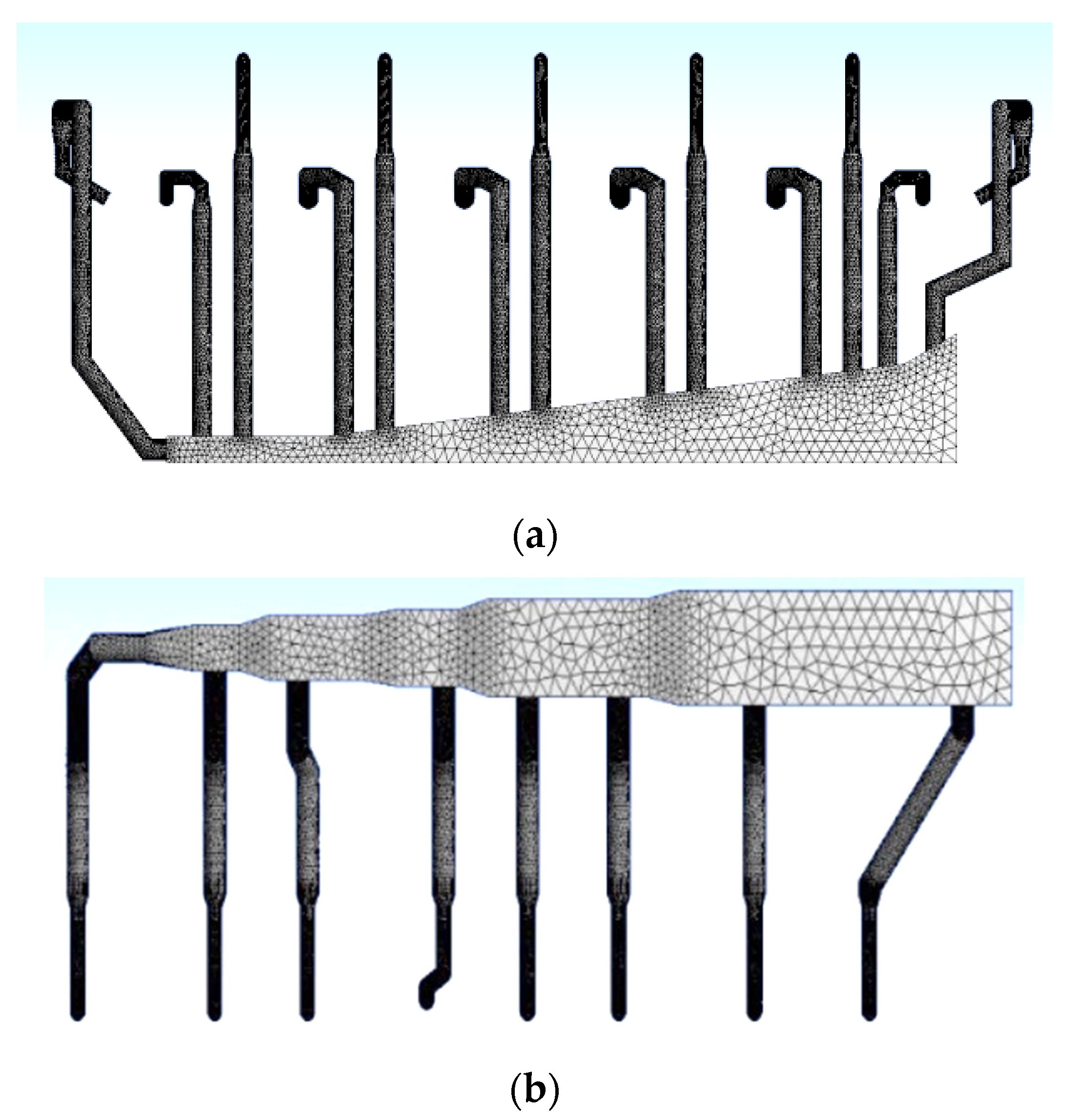
3.1. Overview of Numerical Simulation

Based on the above results of the jet characteristics of each nozzle of the secondary air of the 600 MW supercritical CFB boiler, the internal 1# lower secondary air duct of the 660 MW supercritical CFB boiler was changed from sharing the air inlet pipe with the 2# internal lower secondary air duct (shown in Figure 7) to a separate air inlet pipe. At the same time, the pipe diameter of the local branch pipe was slightly adjusted to further improve the uniformity of the secondary air. To estimate the optimization effect of this design adjustment on the uniformity of the secondary air, numerical simulations were carried out.
The secondary air on both sides of the left and right lower furnaces of the 660 MW ultra-supercritical CFB boiler were arranged symmetrically, and the calculation was carried out for the secondary air box and branch pipe of one side of the furnace. In the calculation process of this paper, the geometric model was discretized by about 600,000 tetrahedral meshes after unrelated verification, as shown in Figure 7. The numerical simulation was under a gas-phase, steady-state condition, and the K − ε RNG model was used to describe the flow of gas, and no slip on the wall was set. To ensure the accuracy of the calculation, all residuals were kept less than 10−4. The calculated working conditions and boundary conditions are shown in Table 2.

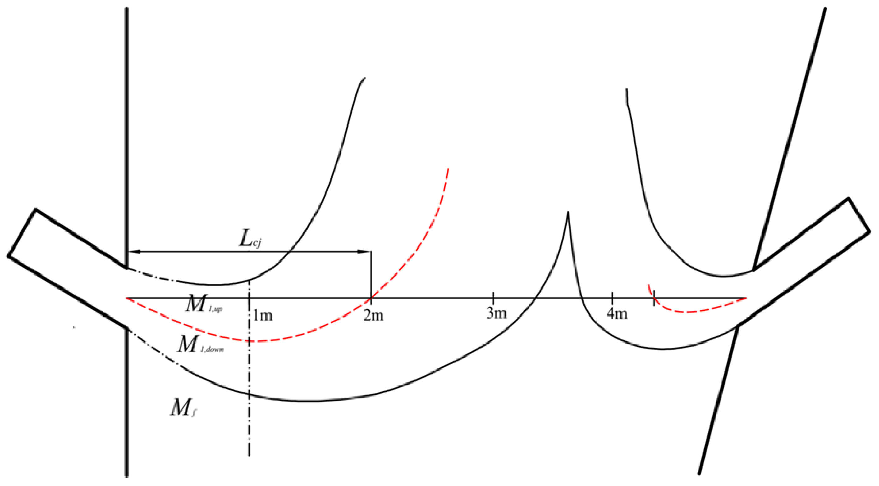
3.2. Evaluation of Nozzle Uniformity of Secondary Air Branch

To evaluate the uniformity of the secondary air, the exit velocity deviation rate is defined as follows [22]:
α = | v v ¯ v ¯ | × 100 %
where v is the gas velocity at the outlet of the secondary air branch pipe, m/s; v ¯ is the average value of gas velocity at the outlet of each secondary air branch pipe, m/s.
The above air velocity deviation rate. α can be regarded as an index to evaluate the uniformity of the secondary air. The greater the α is, the worse the uniformity of secondary air distribution would be.

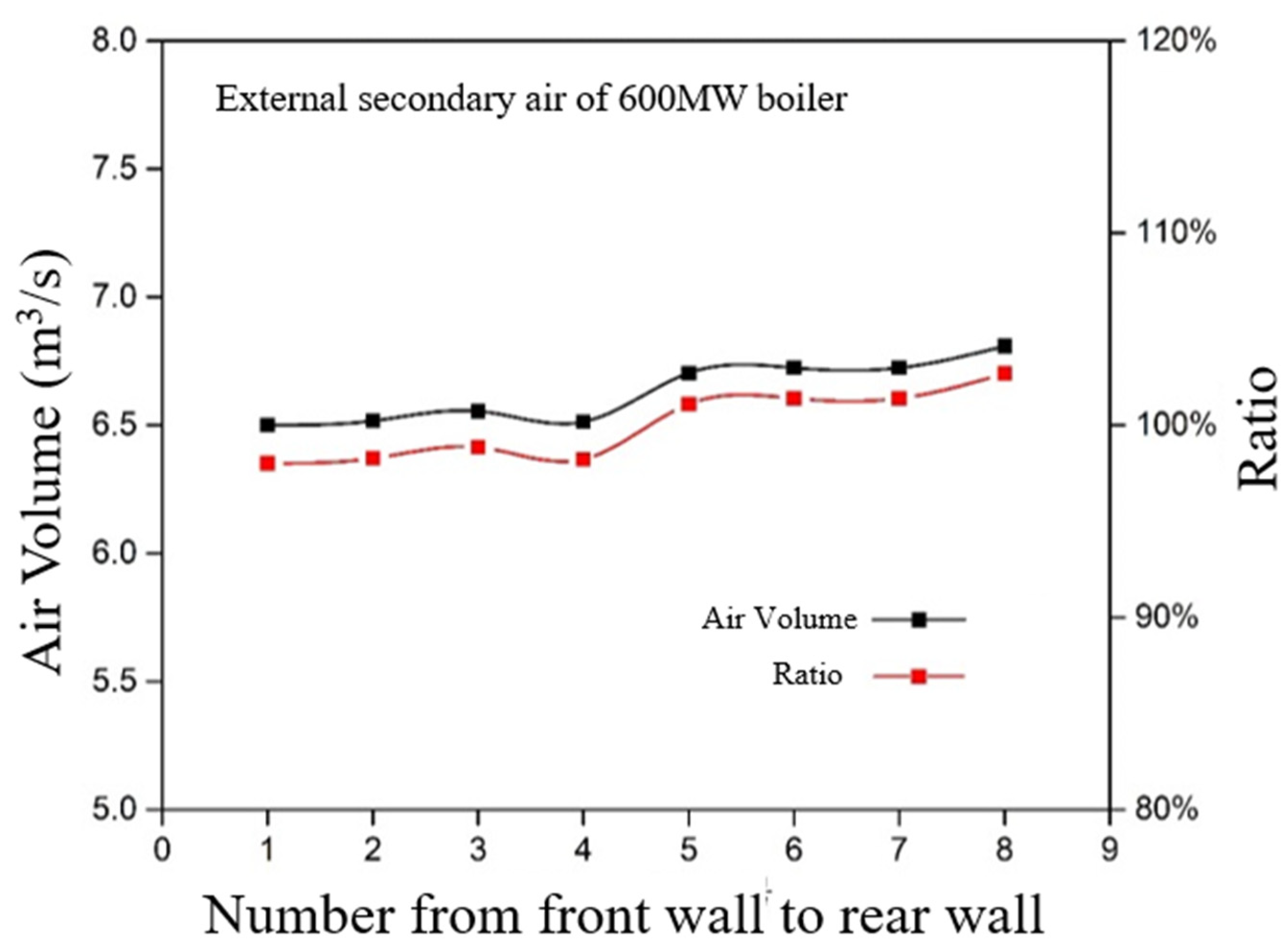
4. Results and Analysis of External Secondary Air

4.1. Overview of Numerical Simulation

Figure 8 shows the typical calculated velocity vector of the secondary air box and the branch pipe. It is found that the secondary air was uniform, and there was no obvious difference in velocity. It indicated that the secondary air box was generally suitable for the branch pipe.
Figure 9 and Figure 10 show the velocity and flow rate of the tests and simulations under the condition of 100% boiler load. It is found that the average velocity of the external secondary air outlet was 33.5 m/s, and the average deviation of the air velocity at the outlet of the eight external secondary air ducts was less than 3% after the optimization and improvement of the ducts. Meanwhile, the secondary air flow of each duct was very close, which means the deviation was small and the secondary air uniformity was perfect.

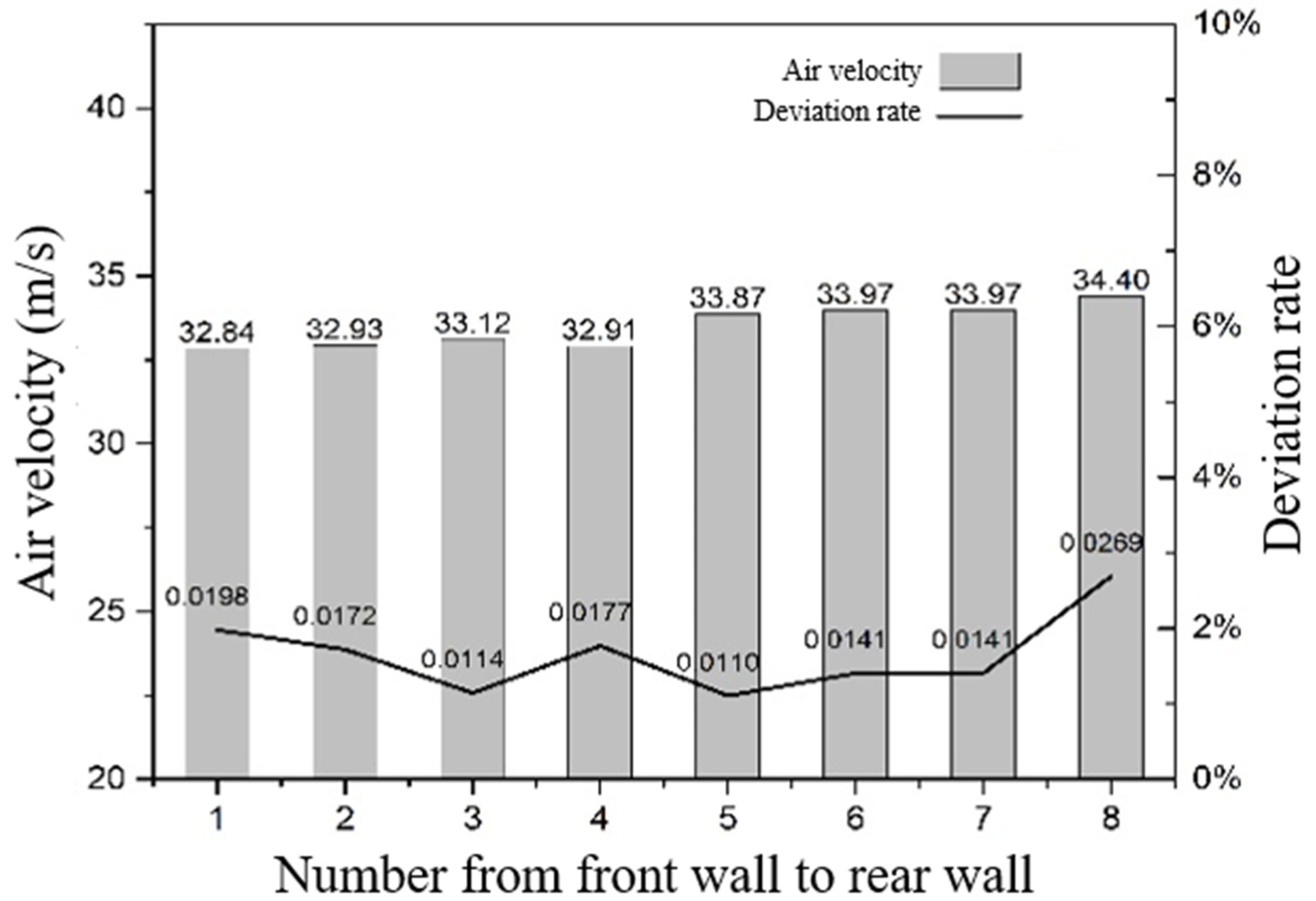
4.2. Results and Analysis of Upper Secondary Air Jet Velocity on Internal Side

The simulation results of the secondary air on the internal side of the 660 MW ultra-supercritical CFB boiler are shown in Figure 11. It is found that the air velocity of the five nozzles on the internal side were basically uniform with a maximum deviation rate less than 1.5%, suggesting that the air distribution uniformity is good.

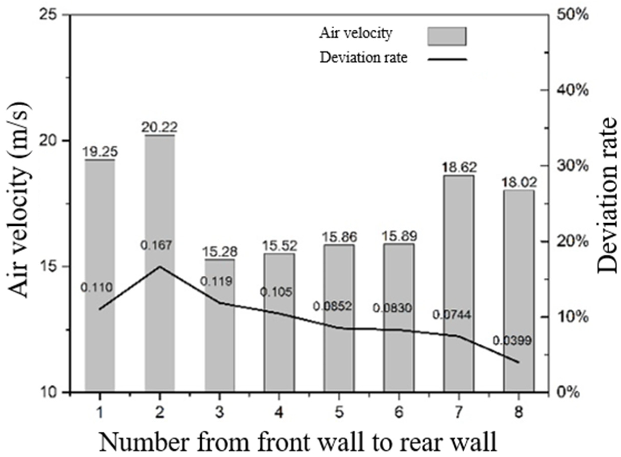
4.3. Results and Analysis of Lower Secondary Air Jet Velocity on Internal Side

The simulation results of the lower secondary air inside the 660 MW ultra-supercritical CFB boiler are shown in Figure 12. It can be seen that the air velocity deviation of eight nozzles of the internal lower secondary air was large, and the air velocity near the front and rear walls was high, the velocities of the middle 3#, 4#, 5#, 6# nozzles were relatively uniform, and the maximum deviation rate was about 17%. However, the deviation level was still slightly better than that of the 600 MW supercritical CFB boiler under actual furnace test conditions.
As a result, the uniformity of the secondary air under the rear wall had the most potential to be further improved. Moreover, it is difficult to completely improve the uniformity of the secondary air in this area only through the fine adjustment of the secondary air branch pipe diameter. Considering the enforceability of processing and installation of different pipe diameters of the secondary air duct in the project, it is proposed to install valves to achieve its uniformity. In addition, measures, such as combined coal feeding, can also be considered to promote the uniformity of the secondary air layout.

5. Conclusions

Based on the actual furnace tests of the secondary air uniformity of the 600 MW supercritical CFB boiler, the structure optimization and numerical simulation of the secondary air branch pipe of the 660 MW ultra-supercritical CFB boiler were carried out, and the following conclusions were obtained:
  • The secondary air tests of the 600 MW supercritical CFB boiler shows that the secondary air distribution in the boiler under rated load was basically uniform, but there is still room for further optimization.
  • Based on the operation experience and test results of the 600 MW supercritical CFB boiler, along the furnace width, the oxygen consumption was lower in the middle but higher on both sides. Along the furnace depth, the oxygen consumption distributions were similar but appeared to be higher at the corners. There were lower combustion shares at the middle of the front and rear walls because of the lower SA flow rates or lack of SA layout. Therefore, more attention should be paid to the air distributions near the water-cooled wall in the design of large-scale CFB boilers. The oxygen concentration was uniform near the rear water-cooled wall, but all exhibited a “decrease–increase–decrease” profile along the horizontal line, which indicated that the trajectory of the secondary air jet was in the shape of first bending downward and then upward.
  • The deviation rate of the internal and lower secondary air reached 17%, and there was optimization space for the secondary air branch pipe layout of the boiler. Its uniformity can be increased by adding valves and other measures. Based on the operation experience and test results of the 600 MW supercritical CFB boiler, the secondary air branch of the 660 MW ultra-supercritical CFB boiler was adjusted, all secondary air branch pipes were adopted with separate air inlet pipes, and the pipe diameter was fine adjusted. The calculation results showed that the optimization effect of the secondary air on the outside and inside was obvious with the velocity deviation of each nozzle less than 3%.
  • Due to the random fluctuation of pressure in the furnace, there was still a certain speed deviation in the speed of the internal lower secondary air nozzle. However, considering the implementation of the project, the uniformity of the secondary air will be realized through further structural optimization, installation of valves, combustion-side adjustment and other measures.

Author Contributions

Conceptualization, L.N. and J.L.; investigation, Q.D., X.L. and L.G.; methodology, D.X. and Z.Y.; writing—original draft preparation, L.N; writing—review and editing, Z.Y. and X.L.; validation, Q.D. and J.L. All authors have read and agreed to the published version of the manuscript.

Funding

This research received no external funding.

Institutional Review Board Statement

Not applicable.

Informed Consent Statement

Not applicable.

Data Availability Statement

Not applicable.

Acknowledgments

Authors are thankful to the Baima plant for valuable support during the long-term field tests.

Conflicts of Interest

The authors declare no conflict of interest.

Nomenclature

ζ Resistance coefficient
λ Resistance coefficient
ρ Density of the fluid, [kg/m3]
ω Fluid velocity, [m/s]
vGas velocity, [m/s]
v ¯ Average gas velocity, [m/s]
αIndex to evaluate the uniformity of secondary air

References

  1. Yue, G.; Cai, R.; Lu, J. From a CFB reactor to a CFB boiler–the review of R&D progress of CFB coal combustion technology in China. Powder Technol. 2017, 316, 18–28. [Google Scholar]
  2. Liu, X.M.; Yang, H.R.; Lyu, J.F. Optimization of Fluidization State of a Circulating Fluidized Bed Boiler for Economical Operation. Energies 2020, 13, 376. [Google Scholar] [CrossRef] [Green Version]
  3. Kalle, N. State of the Art CFB Technology for Flexible Large-Scale Utility Power Production; Power Gen Russia: Moscow, Russia, 2015. [Google Scholar]
  4. Li, D.; Cai, R.; Zeng, Y. Operation characteristics of a bubbling fluidized bed heat exchanger with internal solid circulation for a 550 MW ultra super critical CFB boiler. In Proceedings of the 2nd International Conference on Circulating Fluidized Bed Boiler, China, Qingdao, 21–24 July 2019. [Google Scholar]
  5. Lin, J.J.; Luo, K.; Wang, S.; Sun, L.Y.; Fan, J.R. Particle-Scale Simulation of Solid Mixing Characteristics of Binary Particles in a Bubbling Fluidized Bed. Energies 2020, 13, 4442. [Google Scholar] [CrossRef]
  6. Ling, W.; Lyu, J.; Zhou, T. Research and Development Progress of the 660 MW Ultra-supercritical Circulating Fluidized Bed Boiler. Proc. CSEE 2019, 39, 2515–2524. [Google Scholar]
  7. Deng, Y.; Ansart, R.; Baeyens, J.; Zhang, H. Flue Gas Desulphurization in Circulating Fluidized Beds. Energies 2019, 12, 3908. [Google Scholar] [CrossRef] [Green Version]
  8. Lv, Q.; Song, G.; Wang, D. Study on new 660MW ultra supercritical annular furnace circulating fluidized bed boiler technology. Proc. CSEE 2018, 38, 3022–3032. [Google Scholar]
  9. Ersoy, L.E.; Golriz, M.R.; Koksal, M.T.; Hamdullahpur, F. Circulating fluidized bed hydrodynamics with air staging, an experimental study. Powder Technol. 2004, 145, 25–33. [Google Scholar] [CrossRef]
  10. Xu, L.; Cheng, L.; Zou, Y. Numerical study of gas-solids flow characteristics in a 1000MW supercritical CFB boiler octagonal furnace. Proc. CSEE 2015, 35, 2480–2486. (In Chinese) [Google Scholar]
  11. Nie, L.; Wang, P.; Peng, L. Design of 600MW supercritical Circulating Fluidized Bed Boiler. Power Eng. 2008, 28, 701–706. (In Chinese) [Google Scholar]
  12. Chen, J.; Lu, X.; Liu, H. The Effect of Solid Concentration on the Secondary Air-Jetting Penetration in a Bubbling Fluidized Bed. Powder Technol. 2008, 185, 164–169. [Google Scholar] [CrossRef]
  13. Wu, J.; He, H. The influence on NOx emission of secondary-air in CFB boiler. J. Electr. Power 2014, 29, 542–547, 553. (In Chinese) [Google Scholar]
  14. Kang, Y.; Song, P.; Yun, S. Effects of secondary air injection on gas-solid flow behavior in circulating fluidized beds. Chem. Eng. Commun. 2000, 177, 31–47. [Google Scholar] [CrossRef]
  15. Namkung, W.; Kim, S.D. Radial gas mixing in a circulating fluidized bed. Powder Technol. 2000, 113, 23–29. [Google Scholar] [CrossRef]
  16. Wang, Z.; Qin, M.; Sun, S. Influence of secondary air distribution on the gas-solid mixing and combustion condition in a CFB (Circulating Fluidized Bed) boiler furnace. J. Eng. Therm. Energy Power 2009, 24, 205–210. (In Chinese) [Google Scholar]
  17. Kim, J.H.; Shakourzadeh, K. Analysis and modelling of solid flow in a closed loop circulating fluidized bed with secondary air injection. Powder Technol. 2000, 111, 179–185. [Google Scholar] [CrossRef]
  18. Li, T.; Pougatch, K.; Salcudean, M.; Grecov, D. Mixing of secondary gas injection in a bubbling fluidized bed. Chem. Eng. Res. Des. 2009, 87, 1451–1465. [Google Scholar] [CrossRef]
  19. Zheng, X.; Yan, J.; Wang, J.; Lu, X. Numerical simulation of secondary air penetration depth in a 300MW single-furnace circulating fluidized bed boiler. J. Power Eng. 2009, 29, 801–805, 812. (In Chinese) [Google Scholar]
  20. Zhong, W.; Zhang, M. Jet penetration depth in a two-dimensional spout-fluid bed. Chem. Eng. Sci. 2005, 60, 315–327. [Google Scholar] [CrossRef]
  21. Knoebig, T.; Werther, J. Horizontal reactant injection into large-scale fluidized bed reactors-modeling of secondary air injection into a circulating fluidized bed combustor. Chem. Eng. Technol. 1999, 22, 656–659. [Google Scholar] [CrossRef]
  22. Zhou, J.L.; Wang, Q.H.; Yan, J.; Guo, Q.; Lv, Z.; Zhang, Y.; Lu, X.F. Experimental and Numerical Simulation on the Uniformity of Secondary Air System of Baima 600MW Super. Proc. CSEE 2018, 38, 406–411. (In Chinese) [Google Scholar]
  23. Lu, J. Study on Particle Population Balance and Heat Balance in Large-Scale Circulating Fluidized Bed Boiler. Ph.D. Thesis, Chongqing University, Chongqing, China, 2012. [Google Scholar]
  24. Yan, J.; Lu, X.; Wang, Q.; Li, J.B.; Li, R.X.; Lei, X.J.; Chen, Y.; Liu, C. Field Tests on Combustion Uniformity of the Dilute Phase in a 600MW Supercritical CFB Boiler. Proc. CSEE 2018, 38, 397–405. (In Chinese) [Google Scholar]
  25. Werther, J.; Hartge, E.-U.; Ratschow, L. Simulation support measurements in large circulating fluidized bed combustors. Particuology 2009, 7, 324–331. [Google Scholar] [CrossRef]
  26. Yan, J.; Lu, X.; Wang, Q. Study on the influence of secondary air on the distributions of flue gas composition at the lower part of a 600 MW supercritical CFB boiler. Fuel Processing Technol. 2019, 196, 106035. [Google Scholar] [CrossRef]
  27. Luo, T. Fluid Mechanics; China Machine Press: Beijing, China, 2007. (In Chinese) [Google Scholar]
Figure 1. Structure of the part side of the 600 MW supercritical CFB boiler and the secondary air port layout.
Energies 15 03604 g001
Figure 2. Secondary air box and branch pipe on the part side of the furnace. (number 1 to 8 are pipes numbers).
Energies 15 03604 g002
Figure 3. Test points of the secondary air system (a) front view and (b) side view. (#3 and #4 are sampling points of secondary air pipes).
Energies 15 03604 g003
Figure 4. Oxygen distribution of secondary air along horizontal axis.
Energies 15 03604 g004
Figure 5. The schematic diagram of the SA jet trajectories. (red line: schematic diagram of secondary air flow trajectory).
Energies 15 03604 g005
Figure 6. Oxygen distribution in the furnace section at the upper secondary air nozzle axis.
Energies 15 03604 g006
Figure 7. Grids of secondary air system and pipes. (a) Mesh generation of internal side upper and lower secondary air. (b) Mesh generation of secondary air calculation on the outside.
Energies 15 03604 g007
Figure 8. Velocity vector diagram of secondary air box and each branch pipe.
Energies 15 03604 g008
Figure 9. The calculated value of external side upper secondary air exit velocity.
Energies 15 03604 g009
Figure 10. The calculated value of external side upper secondary air exit flow.
Energies 15 03604 g010
Figure 11. The calculated value of internal side upper secondary air exit velocity.
Energies 15 03604 g011
Figure 12. The calculated value of internal side lower secondary air exit velocity.
Energies 15 03604 g012
Table 1. Working conditions of secondary air jets.
ConditionsBoiler LoadObjectContentSecondary Air Velocity (m/s)
160%BMCRExternal secondary air of #3 and #4 of the right wallFlue gas sampling and analysisInner lower: 19
Inner upper:13
Outer: 22
297%BMCRMeasuring point of right wall near the corner of rear wallFlue gas sampling and analysis; temperature measurement of external secondary airInner lower: 23
Inner upper: 16
Outer: 32
Table 2. Calculation conditions of 660 MW ultra-supercritical CFB boiler.
ItemsBoundary ConditionValue
Inlet of internal air boxVelocity-inlet6.5 m/s, 25 °C
Inlet of external air boxVelocity-inlet14 m/s, 25 °C
Outlet of external secondary airPressure-outlet50 Pa
Lower outlet of internal secondary airPressure-outlet50 Pa
Upper outlet of internal secondary airPressure-outlet50 Pa
Publisher’s Note: MDPI stays neutral with regard to jurisdictional claims in published maps and institutional affiliations.

