Article

Multi-Objective Optimization Design and Analysis of V-Shape Permanent Magnet Synchronous Motor

Department of Mechanical Engineering, National United University, Miaoli 360302, Taiwan
*
Author to whom correspondence should be addressed.
Energies 2022, 15(10), 3496; https://doi.org/10.3390/en15103496
Submission received: 11 April 2022 / Revised: 2 May 2022 / Accepted: 9 May 2022 / Published: 10 May 2022

Abstract

:
Permanent magnet synchronous motors (PMSMs) are the main source of power in modern machine tools and are required to generate a high torque over a wide speed range in order to improve manufacturing efficiency. This study sets out to optimize the rotor design of a PMSM with a rated power, rated speed, rated torque and maximum speed of 34 kW, 2250 rpm, 144.3 N·m and 11,250 rpm, respectively. A multi-objective optimization algorithm is employed to determine the rotor design parameters which maximize the output torque of the PMSM over three different load conditions (no load, rated load and maximum speed load). ANSYS multi-physics simulations are conducted to examine the electromagnetic, the structural field, temperature/flow field, demagnetization parament analysis and map analysis of global characteristics of the optimized PMSM. In general, the results show that the optimized PMSM provides a high torque and high-speed expansion performance, and thus facilitates a wide range of applications from low-speed heavy cutting to high-speed cutting without the need to replace the motor or machine tool.

1. Introduction

Permanent magnet synchronous motors (PMSM) are widely used in industrial machines, manufacturing, electric vehicles, renewable energy applications and so on [1,2,3,4,5]. PMSMs have many advantageous properties, including a high torque density, a high efficiency, a wide speed range and good controllability [6,7,8]. However, as technology in the related application fields continues to advance, many efforts have been made to improve the performance of PMSMs yet further through the development of fractional slot concentrated windings [9,10] and inner permanent magnet synchronous motors (IPMSMs) [11,12], or the application of multimodal design optimization methods [13,14] and differential control strategies. Liang et al. [15] used a combined finite element method (FEM) and deep learning model to optimize the structure of a PMSM and predict the torque efficiency, respectively. The prediction accuracy of the trained model was confirmed by comparing the FE calculation results with the model fitting results. Sun et al. [16] proposed a state feedback control system for a PMSM based on a grey wolf optimization (GWO) algorithm. The results showed that the proposed controller provided a faster response time and a lower overshoot than a conventional proportional integral (PI) controller. Vidanalage et al. [17] developed a multimodal design optimization algorithm to minimize the total active weight and electromagnetic losses of a V-shape IPMSM subject to thermal, mechanical and magnetic constraints. Du et al. [18] performed FE analyses to establish the efficiency map of an IPMSM. The map was then used in an optimization process aimed at minimizing the amount of permanent magnet (PM) material required to construct the IPMSM. The present study employs a multi-objective, multi-physics framework to optimize and evaluate the performance of a V-shape PMSM. In the proposed approach, ANSYS optiSLang software is used to optimize the rotor design parameters of the PMSM using a particle swarm optimization (PSO) algorithm. The optimization process aims to maximize the PMSM torque over three load conditions: no load, rated load and maximum speed. Having optimized the PMSM, multi-physics simulations are conducted to investigate the electromagnetic, structural and temperature properties of the PMSM design. Finally, ANSYS Maxwell simulations are performed to establish the power characteristics and efficiency of the optimized design.

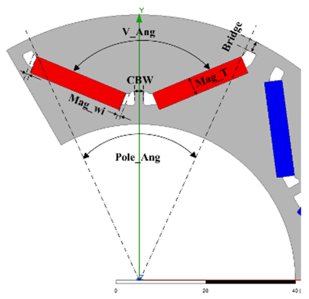
2. PSMS Specification

Table 1 shows the basic specification of the PMSM considered in the present study compared to existing commercial models on the market manufactured by Siemens Ltd. (Shanghai, China) and Ate Gmbh & Co. KG (Eichstätt, Germany). As shown, the motor has a rated torque of 34 kW which is larger than three models from Siemens and Ate. The rated power is assigned as 114.34 kW which is larger than 1FE1084-6WR11 from Siemens and AC-180-220-8 from Ate, and comparable with 1FE1113-6WU11 models from Siemens. The minimum and maximum speed are set as 2250 rpm and 11,250 rpm, respectively, which is wider than models from Siemens and Ate. In addition, the rated current is less than 75 A and the speed expansion ratio is 5 in order to achieve a high torque performance at low speeds. The pole number, slot number and number of slots per pole pair are set as 6, 27 and 9, respectively. The power density is 5995.86 Kw/m3 which is larger than three models from Siemens and Ate. It is noted that the PMSM specification is designed to support both low-speed heavy cutting and high-speed cutting. Consequently, the motor avoids the need to replace the machine tool under different processing conditions and therefore maximizes the processing efficiency and machining precision.
The inner and outer diameters of the rotor were set as 70 mm and 119 mm, respectively, while the inner and outer diameters of the stator were set as 120 mm and 190 mm. The stator distribution ratio was approximately 0.63, and the air gap was fixed as 0.5 mm. Finally, the inner and outer diameters of the central axis were 44 mm and 70 mm, respectively, and the thickness was 200 mm. The tooth width and yoke width are Wt = 9.5 mm and Wy = 14.3 mm, respectively, and the root height and slot opening are ds = 1.3 mm and Ws = 1.7 mm. It is noted that a small slot opening size smooths the energy change between the air gaps and hence reduces the cogging torque.
The magnetic circuit has a fundamental effect on the performance of the PMSM and must therefore be carefully designed [19]. Figure 1 shows the basic arrangement of the permanent magnets in the rotor of the PMSM considered in the present study. It is noted that such a single-layer V-shape and d-axis permanent magnet arrangement provides the highest-efficiency and lowest-cost route for meeting any given torque demand for a PMSM [20]. As shown, the permanent magnets are supported by a bridge structure, which serves to resist the centrifugal load acting on the magnets as the PMSM rotates. The bridge distance and central bridge width (CBW) are critical design parameters since they not only govern the structural strength of the rotor, but also determine the leakage flux. Referring to Figure 1, the permanent magnets have a thickness of Mag_T and a width of Mag_Wi. In addition, the poles of the magnets are separated by an angle of Pole_Ang, while the magnets themselves have an expansion angle of V_Ang. It is noted that the pole expansion angle mainly affects the rotor magnetism, while the V-shape expansion angle mainly determines the d-axis magnetic field, inductance and permanent demagnetization risk of the rotor. The preliminary (i.e., pre-optimization) dimensions of the PMSM are listed in Table 2. The PMSM was assumed to be equipped with a three-phase sine wave drive with a phase difference of 120 degrees. A double-layer-distributed winding method was employed with 10 turns and a coil pitch of 4 mm. The winding parameters were calculated based on Hanselman techniques [21]. The phase offset, 𝐾0, was obtained as 12 °E and the winding factor was given as 0.95. The three-phase drive was implemented using 27 slots with 9 sets of coils per phase. The 10 sets of coils closest to 0 °E were used as the A-phase windings.
Table 3 shows the detailed electrical parameters of the PMSM. As shown, the driving current was 66 Arms, and 10 turns per slot were used. The wire diameter was 2.728 mm (not shown), while the effective cross-sectional area of the coil was 109.5 mm2. Each turn consisted of 24 parallel strands, each with a diameter of 0.56 mm. The current density was assumed to be 14 A/mm2, while the theoretical phase resistance (Rph) was 0.121 Ω. The theoretical copper loss value was 1584 W and the slot occupancy rate was 54%. The rotor material was chosen as 35CS210 stainless steel on account of its high mechanical strength, favorable electromagnetic characteristics and reasonable cost. In addition, the permanent magnets were chosen as N42SH (a rare earth type of neodymium iron boron) with a higher magnetic energy than samarium cobalt, Al-Ni-Co or ferrite, and a temperature rating of 150 °C.

3. Multi-Objective Optimization Design and Analysis

The rotor design parameters of the PMSM were optimized using the multi-objective optimization framework shown in Figure 2. The procedure commenced by specifying the input and output variables and their ranges. A design of experiments (DoE) method was used to generate a series of sampling points, and the response surface method was employed to visualize the relationship between the input and output variables. A sensitivity analysis was then conducted to examine the sensitivity of the output parameters to changes in the input parameters. Finally, a multi-objective optimization algorithm was employed to determine the optimal values of the input parameters. The details of each of the steps in the optimization framework are described in the following.
As shown in Table 4, the optimization process considered eight input parameters, where the first six parameters are described previously in Table 2, and psi1 and psi2 are the current angles of 40 °E and 84 °E, respectively. Referring to Table 5, the output parameters comprised the torques produced by the PMSM under three different working conditions: no load (N = 2250 rpm, Irms = 0 A), rated speed with load (N = 2250 rpm, Irms = 66 A) and maximum speed with load (N = 11,250 rpm, Irms = 66 A). It is noted that the cogging torque is the torque required to overcome the magnetic attraction force between the rotor and the stator. T_2250 and T_11,250 are the average torques at the rated speed and maximum speed, respectively, and T_ripple_2250 and T_ripple_11,250 are the ripple torques at the rated speed and maximum speed, respectively.

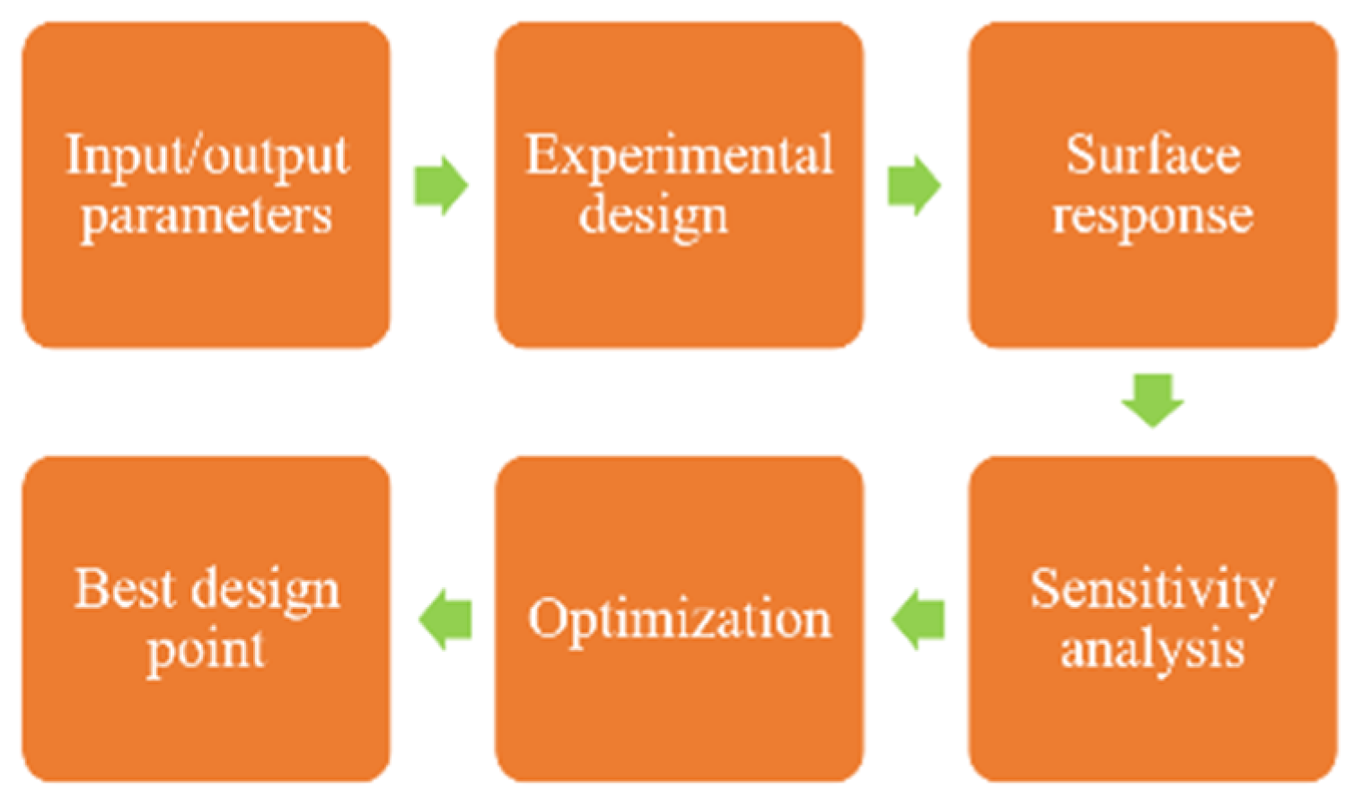
3.1. Design and Experiments Technqiue

As shown in Table 4, the optimization process considered a large number of input variables (eight) and a wide solution space. Thus, for reasons of expediency, the advanced Latin hypercube sampling (ALHS) method [22] was used to sample 100 points in the input design space. It is noted that the ALHS method is described in detail in Ref. [22].

3.2. Sensitivity Analysis

The sensitivity of the input variables was calculated as S T i = 1 V ( Y X i ) / V ( Y ) , where STi is the sensitivity of the ith input variable, V(Y│X~i) is the variance of the input variable to the output variable Y except for input variable Xi and V(Y) is the variance of the output variable Y. Figure 3 presents the corresponding results. It is seen that the total influence degree varies from 93.8% to 99.5%, where the ripple torque has the lowest total influence and the rated torque has the highest total influence.

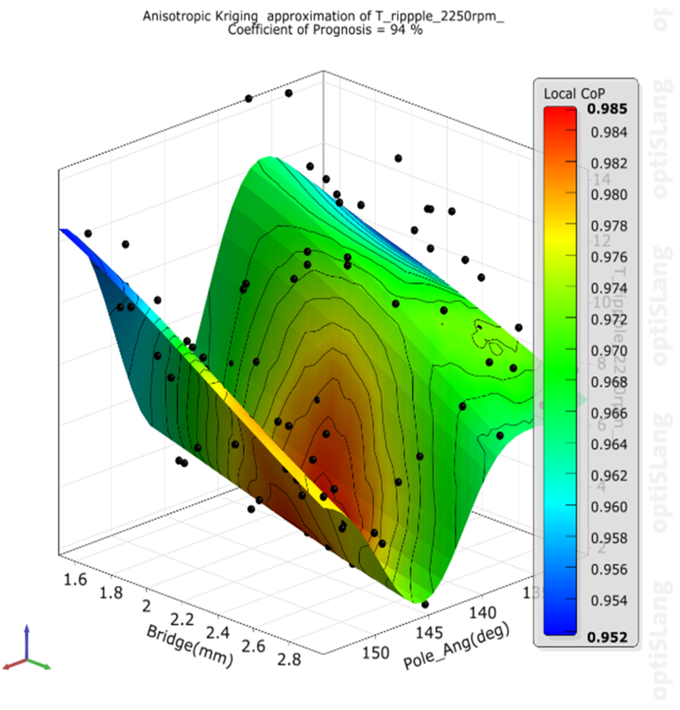
3.3. Response Surface Results

Figure 4 shows the response surface results obtained for each of the seven output parameters Note that for each parameter, the response surface is obtained using an interpolation fitting method and the coefficient of prognosis (CoP) is defined as CoP = 1 S S E P r e d i c t i o n / S S T = 94 % , where S S E P r e d i c t i o n is the sum of squares of errors in predicting a certain output variable and SST is the total variance (equal to the total sensitivity STi). Note also that for each output parameter, the response surface is plotted as a function of the two input parameters with the highest correlation, as indicated in the sensitivity analysis results in Figure 2. (Note that in computing the surface response, the other input variables are assigned their intermediate values in each case). Figure 4a,d,e show the response surfaces for the cogging torque and ripple torque at the rated speed and maximum speed, respectively. In all three cases, the output variables are determined mainly by the Pole_Ang and Bridge parameters. The Pole_Ang determines the magnetic field distribution in the rotor, and hence the space harmonic distribution is also different. The response surfaces of the three variables have a sine wave-like appearance [23,24]. The variable range values of the ripple torque at the rated speed and maximum speed, respectively, are clearly different (i.e., 2~14% and 15~60%, respectively). As the bridge distance reduces, the bridge magnetic saturation increases and gives rise to higher harmonic components in all three output variables. Overall, the cogging torque shows the largest variation with changes in the Pole_Ang and Bridge parameters (±80%, Figure 4a), followed by the ripple torque at the maximum rotor speed (±38%, Figure 4e). As shown in Figure 4b,c, the average torques produced at the rated speed and maximum speed are governed mainly by the Mag_Wi and psi parameters. In general, the magnet width (Mag_Wi) directly affects the size of the magnetic field produced by the rotor. Hence, the average torque increases with increasing Mag_Wi. However, the torque decreases rapidly with an increasing current angle. The sensitivity of the torque to the current psi angle is particularly apparent under the maximum speed condition. As shown in Figure 4f,g, the induced voltage at the rated speed is governed mainly by the current psi and V-Ang input parameters, while the induced voltage at the maximum speed is determined chiefly by Mag_Wi and Mag_T. At the rated speed, the voltage is dominated by the value of psi1 since it has a wider upper and lower limit range. The psi2 at the highest speed is not so sensitive because the voltage cannot drop rapidly with the increase in the current angle similar to the torque.
Figure 5 shows the surface response of the ripple torque with the lowest CoP of 94%. Note that the color bar shows the local value of the CoP. When each input parameter is assigned its intermediate value, the minimum local CoP (95%) occurs at the extreme value of the other variable. The scatter points selected in the experimental design are drawn from an average distribution, and thus do not include the extreme values. As a result, the scattered points are insufficient. Consequently, data errors are more likely to occur at the extreme values of the input variables. However, in the present study, these errors have little impact on the overall problem since the lowest CoP value is quite close to 100%.

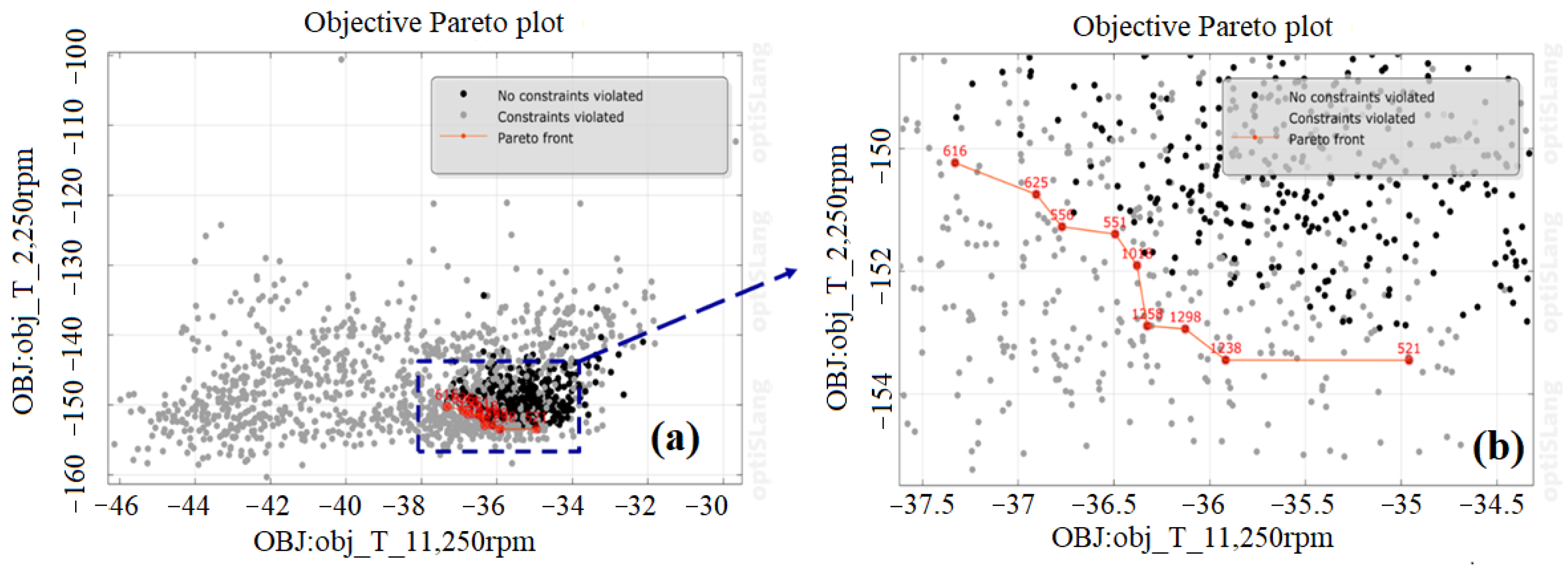
3.4. Optimization Analysis

In performing the optimization process, the aim was to determine the settings of the rotor design parameters which jointly optimized the torque provided by the PMSM under the three load conditions (i.e., no load, rated load and maximum speed load, respectively). As shown in Table 5, the optimization constraints were set as follows: cogging torque <1.52 N·m (5% higher than the required rated torque), ripple torque at rated speed <10%, ripple torque at maximum speed <30%, induced voltage at rated speed <315 V and induced voltage at maximum speed <315 V. The optimization process was performed in ANSYS OptiSLang software using the particle swarm optimization (PSO) algorithm [21]. Briefly, the iterative optimization process was formulated as follows
v i ( k + 1 ) = w v i k + c p r 1 ( P i k x i k ) + c g r 2 ( P g k x i k ) ,
and
x i ( k + 1 ) = x i k + v i ( k + 1 ) ,
where k is the number of iteration steps, v i k is the velocity vector in the current iteration k, v i k + 1 is the velocity vector in the following iteration k + 1, w is the weight of inertia, cp is the individual particle acceleration, Cg is the global acceleration, R1 and R2 are random numbers between 0 and 1, P i k is the local optimal particle position, P g k is the global optimal particle position, x i k is the particle position in the current iteration k, and x i k + 1 is the particle position in the following iteration k + 1. As described in [21], the velocity vector for each particle was updated at the end of each iteration by reference to both its current position and the global optimal particle position in such a way as to gradually approach the optimal solution.

3.5. Optimization Results and Discussion

Figure 6 shows the optimization results. The x-axis shows the average torque at the maximum speed of 11,250 rpm, while the y-axis shows the torque at the rated speed of 2250 rpm. The data points show the optimization results for each sample (1700 in total). The total run time of the PSO algorithm was less than 10 min. It is noted that all of the data points have a negative value since, in an optimization process, the general goal is uniformly converted into a minimum calculation. Therefore, if both objectives are to be maximized, the optimization software automatically converts them to negative values for calculation purposes. The gray data points are infeasible solutions which do not meet certain of the five constraints, while the black data points are feasible solutions which satisfy all five constraints. Finally, the red dots show the optimal solutions (Figure 6a). Figure 6b shows the corresponding Pareto front of the optimal solutions. Table 6 shows the optimized values of the eight input parameters. It is noted that the optimized value of psi2 was found to be 83.5 °E, but is rounded up to 84 °E in the table. Table 7 shows the optimized values of the seven output parameters. It is seen that the optimal design of the rotor auxiliary slot decreases the cogging torque by 1.01 N·m, reduces the ripple torque at the rated speed to 5.5% and increases the ripple torque at the maximum speed to 25.2%. However, the average torques at the rated speed and maximum are increased by +2.99 N·m and +0.98 N·m, respectively.
Figure 7 shows the rotor design before and after the optimization process. It is seen that the two designs are very similar. However, the electromagnetic characteristics of the two rotors may still be very different. Accordingly, as described in the following section, ANSYS multi-physics simulations were performed to study the feasibility of the optimized design under the three considered working conditions (no load, rated load and maximum speed load).

4. Multi-Physical Analysis Results and Discussion

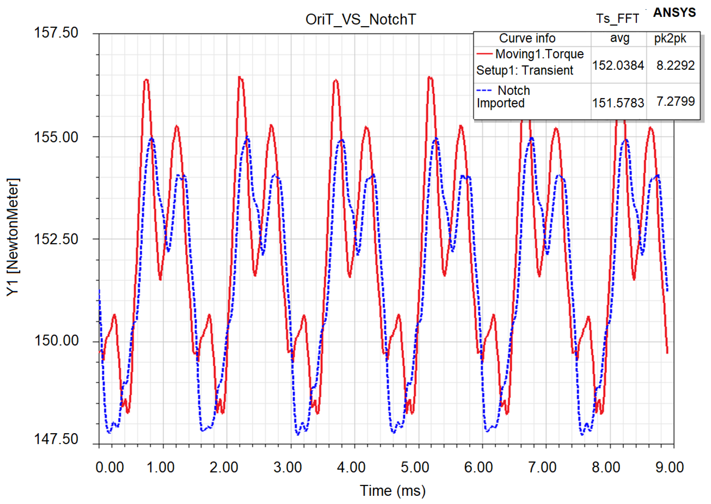
4.1. Optimal Design and Analysis of Electromagnetic Field

Further simulations were performed to examine the effects of the size and position of the rotor rivet hole on the magnetic field induced in the rotor and hence the torque performance of the motor. Note that the function of the rotor rivet hole is to fix the rotor covers on either end of the motor in order to prevent the permanent magnets from becoming loosened axially. The simulations commenced by fixing the center of the rivet hole at (0,50) in the 2D coordinate system. The average torque and ripple torque were then calculated at the rated speed (N = 2250 rpm and Irms = 66 A) for three different rivet hole diameters: 3 mm, 4 mm and 5 mm, as shown in Figure 8.
Table 8 shows the simulation results. It is seen that the average torque and ripple torque both reduce as the rivet hole diameter increases. For example, when the hole diameter is increased to 5 mm, the average torque reduces by 0.8% compared to the original design, while the ripple torque reduces by 0.5%. Thus, the optimal value of the rivet hole diameter was specified as 3 mm.
A further series of simulations were performed to determine the optimal location of the rivet hole. The corresponding results are presented in Table 9 for center coordinate positions of (0,50), (0,52) and (0,54), respectively. As shown, the magnetic path weakens when the rivet hole approaches the outer diameter of the rotor too closely (i.e., center coordinate position (0,54)), and the generated torque reduces accordingly. For center coordinate positions of (0,50) and (0,52), respectively, the average torque has the same value (152.03 N·m). Thus, the optimal center coordinate position of the rivet hole was selected as (0,52). The basic auxiliary groove design considered in the present study consisting of two symmetrical d-axis auxiliary grooves between each pole. The design parameters include the expansion angle between the two grooves (θrs), the left angle of a single groove (θl), the right angle of a single groove (θr) and the groove depth (drs). Simulations were performed to optimize the auxiliary groove design by adjusting the design parameters in the following ranges: θrs = 90 °E–160 °E, (θl,θr) = 10~20 °M and drs = 0.3 mm. Figure 9 shows the rated torque waveforms before (red line) and after (blue line) optimization, respectively. Note that the optimal groove parameters were determined to be θrs = 127 °E, θl = 16 °M, θr = 14 °M and drs = 0.3 mm. It is observed that the optimized design results in a significant reduction in the ripple torque at the expense of only a minor loss in the average torque
Table 10 shows the output parameters of the PMSM before and after the optimization of the rotor auxiliary slot. It is seen that the optimal design of the rotor auxiliary slot increases the cogging torque by round 1.01 N·m, reduces the ripple torque at the rated speed to 4.8% and increases the ripple torque at the maximum speed to 38.5%.

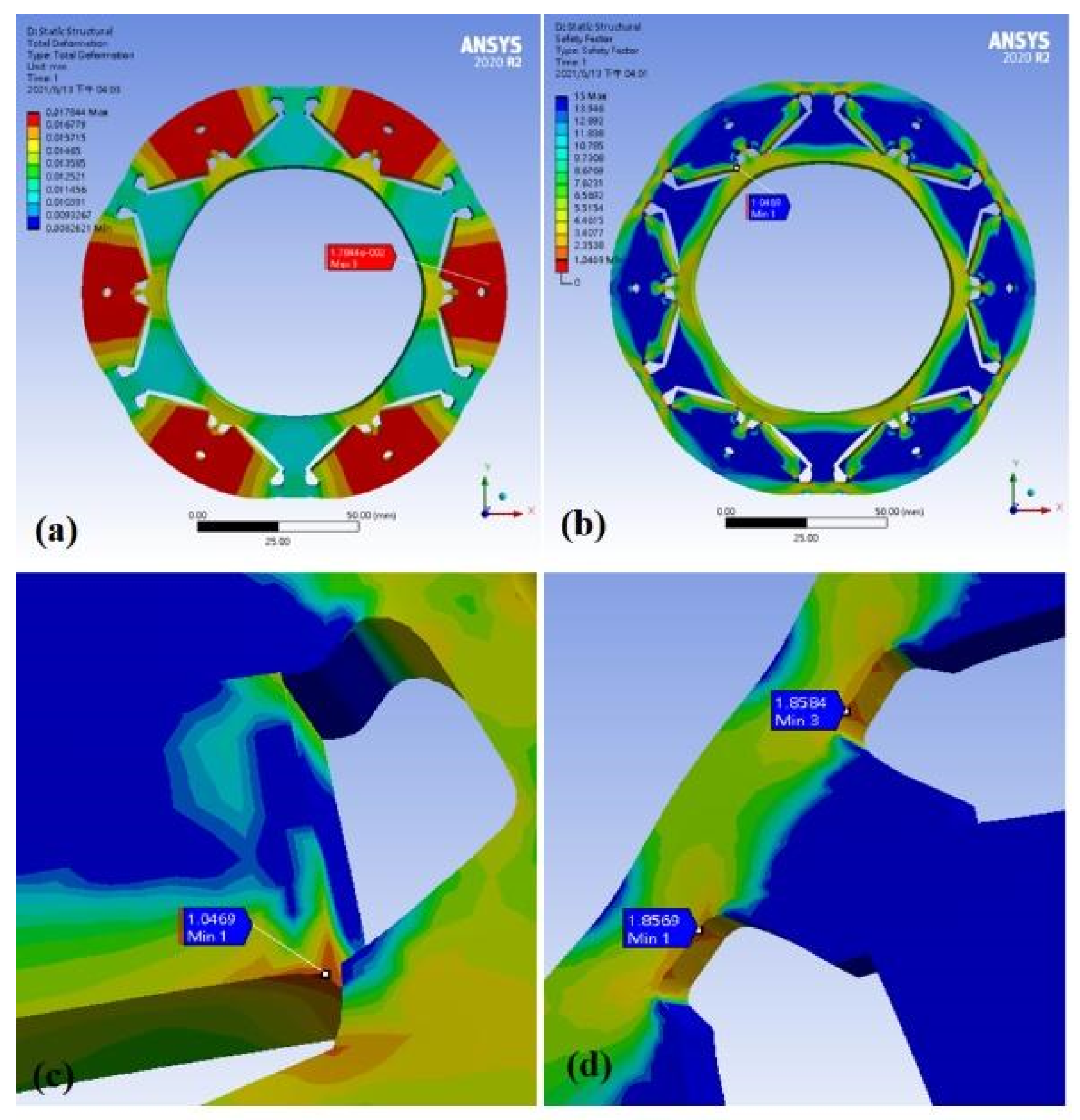
4.2. Structural Field Analysis

Multiphysics simulations were additionally performed to investigate the structural integrity of the rotor under the maximum speed condition of 11,250 rpm. In performing the simulations, the rotor body and permanent magnets were assumed to be one part; the stacking situation, the permanent magnet adhesive force and rotor body residual stress were ignored. In addition, the side of each permanent magnet was assumed to be in frictionless contact with the side near the inner diameter of the rotor, while the side near the outer diameter was assumed to be in full restraint contact. The inner diameter of the rotor was restrained by a cylindrical support; however, radial deformation was allowed. Finally, the yield strengths of the 35CS210 rotor and N42SH permanent magnets were set as 425 MPa and 75 MPa, respectively. As shown in Figure 10a, the maximum rotor deformation is 0.018 mm and occurs at the center of the d-axis of each pole. The deformation is significantly smaller than the air gap (0.5 mm), and thus does not produce interference between the stator and the rotor. Figure 10b,c show that the minimum safety factor of the rotor assembly is 1.05 and is located at the inner corner of the magnet, which serves as a stress raiser under the effects of the centrifugal force produced during rotation. Nonetheless, the safety factor is still higher than the yield stress of the permanent magnet itself, and hence no permanent deformation occurs. As shown in Figure 10d, the minimum safety factor of the rotor is 1.86 and occurs at the outer magnetic barrier of the permanent magnet. Overall, the simulation results confirm that the optimized rotor design faces no risk of permanent deformation or structural damage.

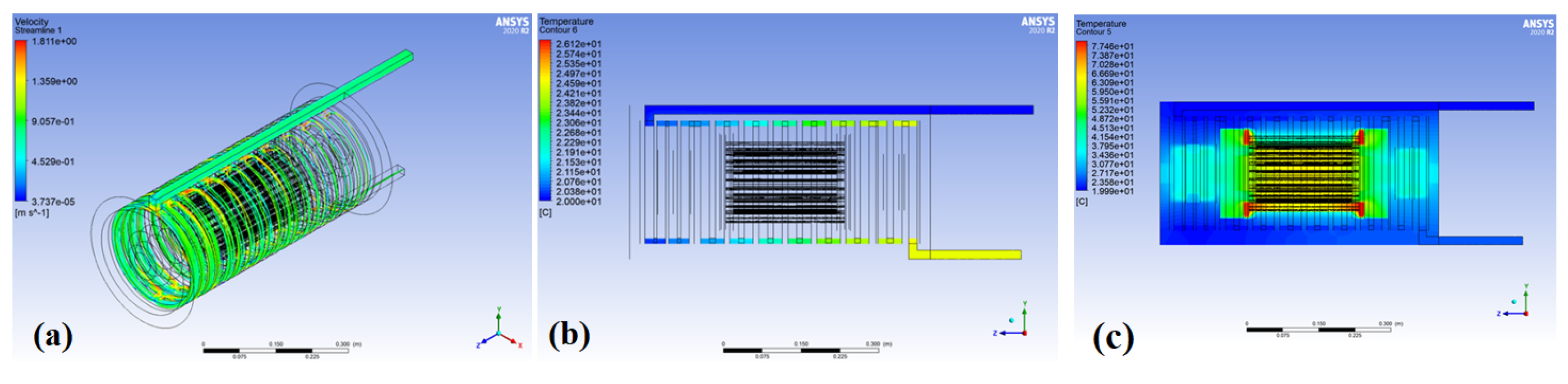
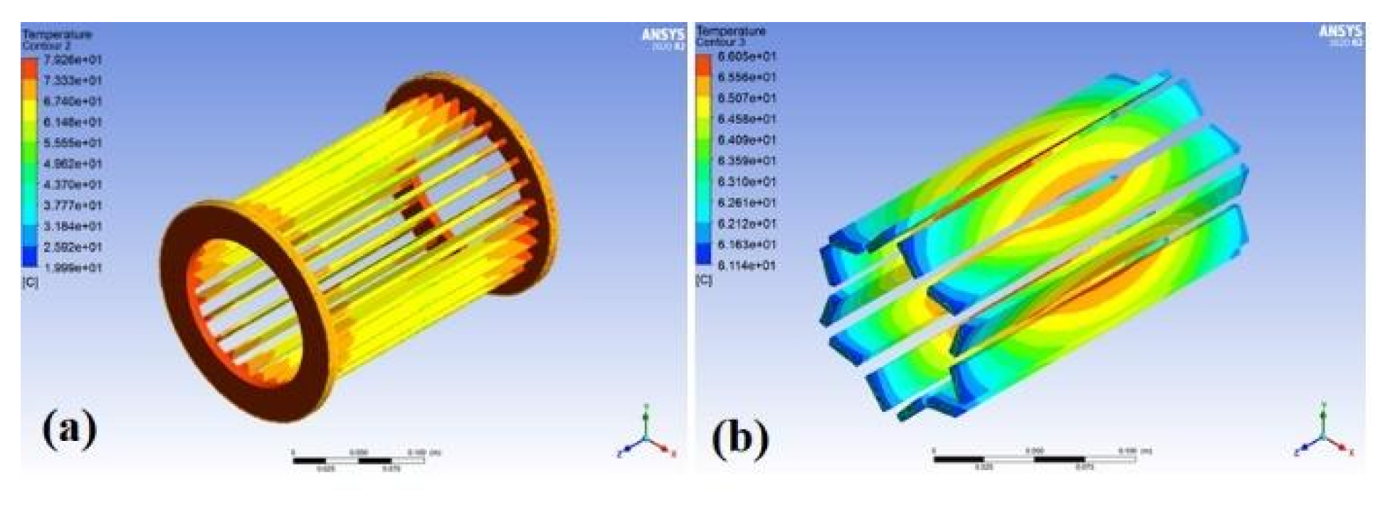
4.3. Temperature and Flow Field Analysis

The proposed PSMS losses are mainly contributed by the copper losses, core losses, mechanical losses and other losses. At the ideal temperature of 20 °C, the copper losses are calculated as 1584 W. The core losses consist of hysteresis losses, Eddy current losses and excess losses and are simulated obtained as 1.93 kw where core loss at stator and rotor are 1.48 kw and 0.45 kw, respectively. The mechanical losses are caused by the friction loss of the front and rear shaft and are obtained as 1.35 kw. Finally, the other losses are assigned as 1–5% of efficiency.
Further multi-physics simulations were performed to analyze the temperature and flow field distributions of the optimized PMSM. When performing the simulation, the outer diameter of the overall spindle was set as 300 mm, while the maximum length was given as 580 mm. The insulation breakdown temperature of the coil was set as 150 °C. Finally, the Reynolds number and flow rate of the cooling water flow were given as 10,000 and 0.138 kg/s, respectively. Figure 11a,b show the simulated velocity and temperature distributions of the water-cooling flow, respectively. It is seen that the inlet and outlet temperatures of the cooling water-flow are around 20 °C and 25 °C, respectively. Figure 11c shows the simulated temperature distribution of the entire spindle. It is seen that the maximum temperature (77.46 °C) occurs at the end of the stator coil. This finding is reasonable since the epoxy resin covering the coil has a low thermal conductivity, which causes the heat to accumulate at the end of the coil before it is transferred to the water-cooled shell.
Figure 12 shows the simulated temperature distributions in the coil and permanent magnet, respectively. As shown in Figure 12a, the temperature in the middle section of the coil is dissipated by the stator fins and is hence relatively lower than that at the two ends of the coil, which suffer the heat accumulation effect described above. Referring to Figure 12b, the maximum temperature of the permanent magnets is around 66 °C. Interestingly, the temperature distribution of the magnets is the opposite of that of the coil since the middle section of the magnets is far removed from the water-cooled shell and thus cannot easily dissipate heat. Overall, the simulation results show that the maximum temperature of the coil is 77 °C, which is far lower than the insulation breakdown temperature of 150 °C. Similarly, the maximum temperature of the permanent magnet is about 66 °C, which is not easy for permanent demagnetization to occur. Thus, overall, the results confirm that the water-cooling design is sufficient to protect the motor assembly from thermal damage.

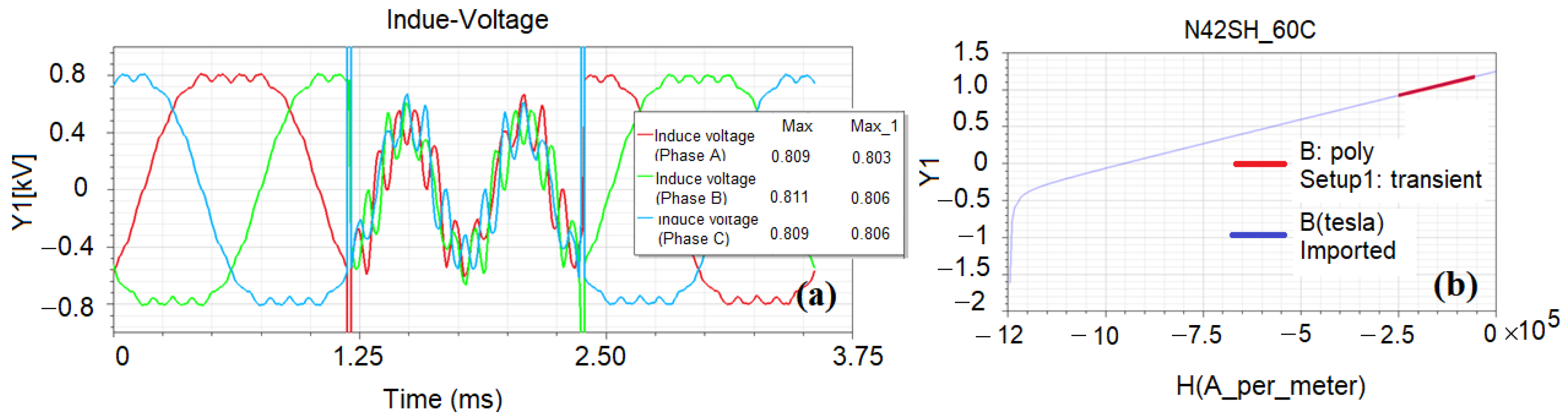
4.4. Demagnetization of Permanent Magnets Analysis

When performing the demagnetization of permanent magnet analysis, the full rated current is applied on the d-axis at the rotor position of 40° to 80°, the simulation results of induced voltage waveform are shown as Figure 13a. It can be observed that the change in the induced voltage waveform in the middle part is completely driven by the rated current applied on the d-axis. The values of induced voltage before (left part) and after (right part) applied rated current on the d-axis are 811 V and 807 V, respectively. Figure 13b shows the demagnetization curve of a permanent magnet of the designed PSMS (red line) and the standard N42SH material at 60 °C. It is confirmed that the permanent demagnetization phenomenon is indeed unlikely to occur during the field weakening region at the highest speed.

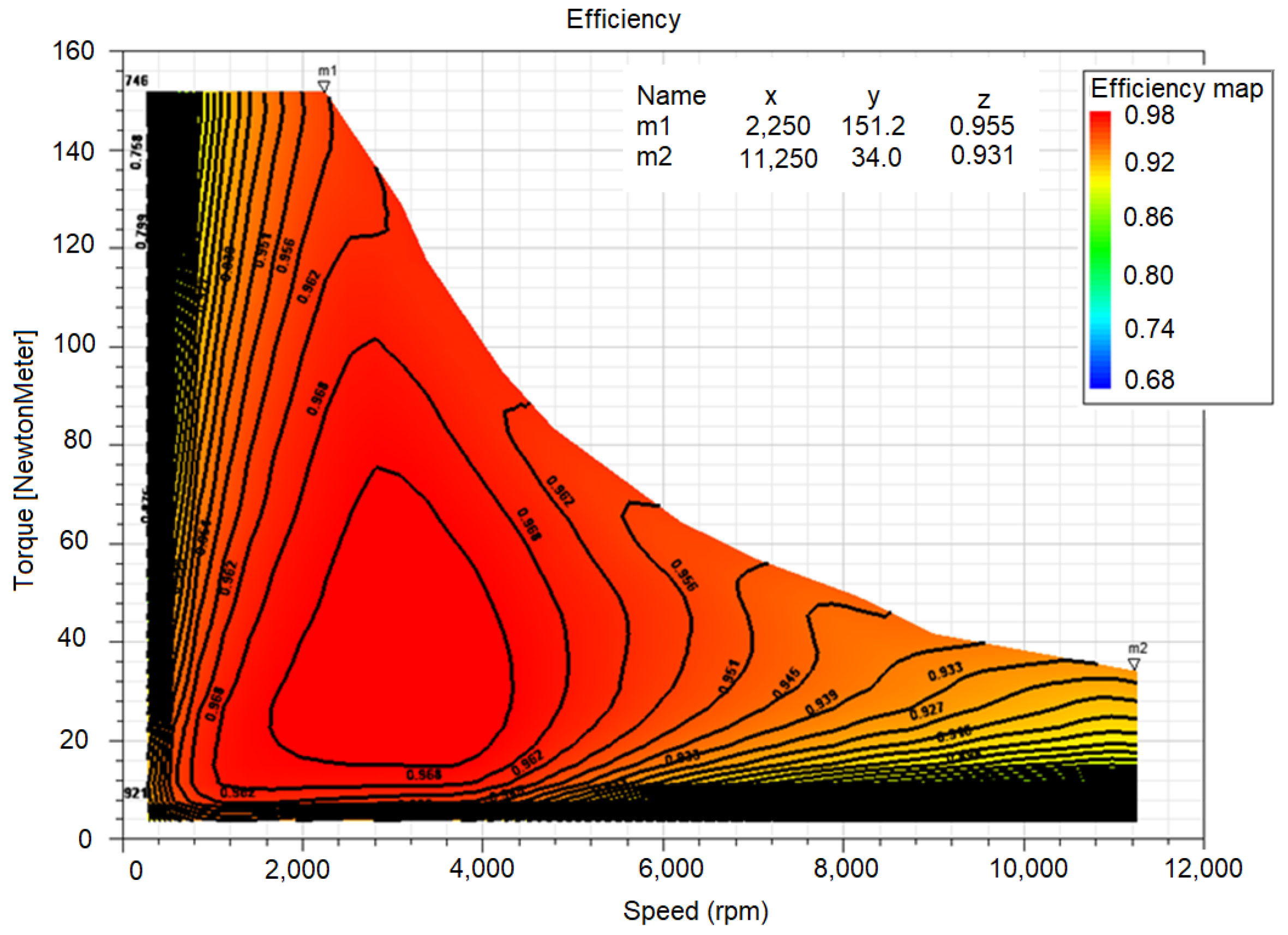
4.5. Map Analysis of Global Characteristics of Optimized PMSM

A final series of simulations was performed to examine the power, torque and efficiency characteristics of the optimized PMSM. The number of current, current angle and speed sampling points was set as 6, 15 and 4, respectively. In addition, the line voltage, rated current, phase resistance and coil inductance were set as 380 Vrms, 66 Arms, 0.095 Ω and 0.087 mH, respectively. The efficiency map calculation took into account the iron loss and copper loss at different frequencies and the voltage drop caused by leakage inductance, but ignored the change in temperature of the coil and permanent magnets at different speeds. The efficiency map was calculated using a total of 360 sampling points. Figure 11 shows the simulation results for the power and torque characteristics of the PMSM. As shown in Figure 14a, the rated power is around 44.5 kW, while the rated speed is approximately 2250 rpm, and the maximum speed reaches 11,250 rpm. In other words, the performance of the PMSM is consistent with the required specification (see Table 1). As shown in Figure 14b, the maximum loss is equal to approximately 2975 W and occurs at the maximum speed of 11,250 rpm. It is thought that the loss is caused mainly by the eddy current loss resulting from the operation of the motor at a 5-time frequency expansion. As shown in Figure 14c, the optimized PMSM achieves a maximum output power of 42.43 kW. (Note that the output power map is obtained simply by subtracting the loss from the input power, i.e., P o u t = P i n P l o s t ). Finally, as shown in Figure 14d, the rated torque is 151.2 N·m, which is around 0.21% smaller than the target specification (i.e., 151.52 N·m, see Table 5). In addition, the torque produced under the maximum speed condition is around 34 N·m and is hence approximately 13.3% higher than the target specification (i.e., 30 N·m, see Table 5). (Note that the output torque is obtained by dividing the output power by the speed, i.e., T o u t = P o u t / ω m ).
Figure 15 shows the efficiency map obtained by dividing the output power by the input power ( P e f f = P o u t / P i n ). The maximum efficiency is around 97%, while the efficiency at the rated speed is 96%, and that at the highest speed is about 93%. The efficiency of the proposed design thus exceeds the target specification at the global operating point. Moreover, the safety factors of the rotor and permanent magnets also exceed the requirement. Thus, the overall feasibility of the proposed optimized PMSM design is confirmed.

5. Conclusions

The rotor design parameters of a PMSM were optimized using a PSO multi-objective optimization algorithm based on the ALHS technique. The aim of the optimization process was to jointly maximize the output torque of the PMSM under rated speed (2250 rpm) and maximum speed (11,250) conditions, respectively. The sensitivity results show that the ripple torque has the lowest total influence of 93.8% and the rated torque has the highest total influence of 99.5%. The validity of the optimization results was confirmed by multi-physics simulations. The electromagnetic field analysis results have shown that the optimized design of rivet hole diameter and position results in a significant reduction in the ripple torque at the expense of only a minor loss in the average torque. Furthermore, the optimal design of the rotor auxiliary slot increases the cogging torque by round 1.01 N·m, reduces the ripple torque at the rated speed to 4.8% and increases the ripple torque at the maximum speed to 38.5%. The structural field analysis results have shown that the minimum safety factor of the rotor assembly is 1.05 and is located at the inner corner of the magnet. Nonetheless, the safety factor is still higher than the yield stress of the permanent magnet itself, and hence no permanent deformation occurs. In addition, the maximum temperature of the coil and the permanent magnet are 77 °C and 66 °C, respectively, which is far lower than the insulation breakdown temperature of 150 °C. Thus, it is confirmed that the water-cooling design is sufficient to protect the motor assembly from thermal damage. Notably, the demagnetization of permanent magnets analysis confirmed that the permanent demagnetization phenomenon is unlikely to occur during the field weakening region at the highest speed. Finally, the map analysis of global characteristics of the optimized PMSM has shown that the optimal PMSM design reduces the cogging torque and the optimized PMSM has an efficiency of 96% at the rated speed and 93% at the maximum speed. In the future, the optimization process will aim to reduce the moment of the inertia of the rotor and the PMSM driver system will also be designed.

Author Contributions

Conceptualization, methodology, S.-C.W.; software, validation, formal analysis, investigation, resources and data curation, Y.-C.N.; writing—original draft preparation, writing—review and editing and visualization, S.-C.W. and Y.-C.N.; supervision, project administration and funding acquisition, S.-M.H. All authors have read and agreed to the published version of the manuscript.

Funding

This research received no external funding.

Institutional Review Board Statement

Not applicable.

Informed Consent Statement

Not applicable.

Data Availability Statement

Not applicable.

Acknowledgments

The authors gratefully acknowledge the software support provided to this study by the ANSYS software company.

Conflicts of Interest

The authors declare no conflict of interest.

References

  1. Wang, A.; Jia, Y.; Soong, W.L. Comparison of five topologies for an interior permanent-magnet machine for a hybrid electric vehicle. IEEE Trans. Magn. 2011, 47, 3606–3609. [Google Scholar] [CrossRef]
  2. Dajaku, G.; Hofmann, H.; Hetemi, F.; Dajaku, X.; Xie, W.; Gerling, D. Comparison of two different ipm traction machines with concentrated winding. IEEE Trans. Ind. Electron. 2016, 63, 4137–4149. [Google Scholar] [CrossRef]
  3. Bozhko, S.; Rashed, M.; Hill, C.I.; Yeoh, S.S.; Yang, T. Flux-weakening control of electric starter–generator based on permanent-magnet machine. IEEE Trans. Transp. Electr. 2017, 3, 864–877. [Google Scholar] [CrossRef]
  4. Sun, X.; Jin, Z.; Wang, S.; Yang, Z.; Li, K.; Fan, Y.; Chen, L. Performance improvement of torque and suspension force for a novel five-phase BFSPM machine for flywheel energy storage systems. IEEE Trans. Appl. Supercond. 2019, 29, 0601505. [Google Scholar] [CrossRef]
  5. Liu, X.; Chen, H.; Zhao, J.; Belahcen, A. Research on the performances and parameters of interior PMSM used for electric vehicles. IEEE Trans. Ind. Electron. 2016, 63, 3533–3545. [Google Scholar] [CrossRef]
  6. Feng, S.; Jiang, W.; Zhang, Z.; Zhang, J.; Zhang, Z. Study of efficiency characteristics of Interior Permanent Magnet Synchronous Motors. IEEE Trans. Magn. 2018, 54, 8108005. [Google Scholar]
  7. Tiegna, H.; Amara, Y.; Barakat, G. Study of cogging torque in axial flux permanent magnet machines using an analytical model. IEEE Trans. Magn. 2014, 50, 845–848. [Google Scholar] [CrossRef]
  8. Shanshal, A.; Hoang, K.; Atallah, K. High-performance ferrite permanent magnet brushless machines. IEEE Trans. Magn. 2017, 55, 8104504. [Google Scholar] [CrossRef] [Green Version]
  9. Dutta, R.; Pouramin, A.; Rahman, M.F. A novel rotor topology for high performance fractional slot concentrated winding interior permanent magnet machine. IEEE Trans. Energy Convers. 2021, 36, 658–670. [Google Scholar] [CrossRef]
  10. Carraro, E.; Bianchi, N.; Zhang, S.; Koch, M. Design and performance comparison of fractional slot concentrated winding spoke type synchronous motor with different slot pole combinations. IEEE. Trans. Ind. Appl. 2018, 54, 2276–2284. [Google Scholar] [CrossRef]
  11. Han, J.H.; Lee, J.; Kim, W.H. A study on optical design of the triangle type permanent magnet in IPMSM rotor by using the bo-behnken design. IEEE. Trans. Magn. 2015, 51, 8200704. [Google Scholar]
  12. Han, Z.; Liu, J.; Yang, W.; Pinhal, D.B.; Reiland, N.; Gerling, D. Improved online maximum-torque-per-ampere algorithm for speed controlled interior permanent magnet synchronous machine. IEEE Trans. Ind. Electron. 2019, 67, 3398–3408. [Google Scholar] [CrossRef]
  13. Zhang, G.; Yu, W.; Hua, W.; Cao, R.; Qiu, H.; Guo, A. The design and optimization of an interior, permanent magnet synchronous machine applied in an electric traction vehicle requiring a low torque ripple. Appl. Sci. 2019, 9, 3634. [Google Scholar] [CrossRef] [Green Version]
  14. You, Y.M. Multi-objective optimization of a permanent magnet synchronous motor based on an automated design and analysis procedure. Microsyst. Technol. 2020, 26, 3477–3488. [Google Scholar] [CrossRef]
  15. Jin, L.; Wang, F.; Yang, Q. Performance analysis and optimization of permanent magnet synchronous motor based on deep learning. In Proceedings of the 20th International Conference on Electrical Machines and Systems (ICEMS), Sydney, NSW, Australia, 11–14 August 2017; pp. 1–5. [Google Scholar]
  16. Sun, X.; Jin, Z.; Cai, Y.; Yang, Z.; Chen, L. Grey wolf optimization algorithm based state feedback control for a bearingless permanent magnet synchronous machine. IEEE Trans. Power Electron. 2020, 35, 13631–13640. [Google Scholar] [CrossRef]
  17. Vidanalage, B.D.S.G.; Toulabi, M.S.; Filizadeh, S. Multimodal design optimization of V-shaped magnet IPM synchronous machines. IEEE Trans. Ener. Conver. 2018, 33, 1547–1556. [Google Scholar] [CrossRef]
  18. Du, J.; Wang, X.; Lv, H. Optimization of magnet shape based on efficiency map of IPMSM for EVs. IEEE Trans. Appl. Supercond. 2016, 26, 1–7. [Google Scholar] [CrossRef]
  19. Han, S.H.; Jahns, T.M.; Soong, W.L.; Güven, M.K.; Illindala, M.S. Torque ripple reduction in interior permanent magnet synchronous machines using stators with odd number of slots per pole pair. IEEE Trans. Energy Convers. 2010, 25, 118–127. [Google Scholar] [CrossRef]
  20. Pouramin, A.; Dutta, R.; Rahman, M.F. Preliminary study on differences in the performance characteristics of concentrated and distributed winding ipm machines with different rotor topologies. In Proceedings of the IEEE Energy Conversion Congress and Exposition (ECCE), Cincinnati, OH, USA, 1–5 October 2017. [Google Scholar]
  21. Hanselman, D.C. Minimum torque ripple, maximum efficiency excitation of brushless permanent magnet motors. IEEE Trans. Ind. Electron. 1994, 41, 292–300. [Google Scholar] [CrossRef]
  22. Huntington, D.E.; Lyrintzis, C.S. Improvements to and limitations of Latin hypercube sampling. Probabilistic Eng. Mech. 1998, 13, 245–253. [Google Scholar] [CrossRef]
  23. Li, K.; Wang, Y. Maximum torque per ampere (MTPA) control for IPMSM drives based on a variable-equivalent-parameter MTPA control law. IEEE Trans. Power Electron. 2018, 34, 7092–7102. [Google Scholar] [CrossRef]
  24. Yun, B.C.; Han, K.K.; Lee, D.Y.; Kang, G.H.; Jang, K.B.; Shin, H.K.; Kim, G.T. A study on the improvement of dynamic characteristics in Interior Permanent Magnet motor by rotor shape design. In Proceedings of the 2008 International Conference on Electrical Machines and Systems, Wuhan, China, 17–20 October 2008; pp. 3126–3130. [Google Scholar]
Figure 1. Illustration of the preliminary design of PMSM.
Energies 15 03496 g001
Figure 2. Optimization process.
Energies 15 03496 g002
Figure 3. Sensitivity analysis results.
Energies 15 03496 g003
Figure 4. Response surfaces of: (a) cogging torque with two variables Pole_Ang (56.7%), Bridge (23.9%), variable range 0.25~2.25 N·m (±80%); (b) average torque (2250 rpm) with two variables Mag_Wi (36.5%), psi1 (19.7%), variable range 105~155 N-m (±19%); (c) average torque (11,250 rpm) with two variables psi2 (61.3%), Mag_Wi (15.3%), variable range 30~44 N-m (±19%); (d) ripple torque (2250 rpm) with two variables Pole_Ang (67.7%), Bridge (18.8%), variable range 2~14% (±6%); (e) ripple torque (11,250 rpm) with two variables Pole_Ang (80.8%), Bridge (18.3%), variable range 15~60% (±38%); (f) induced voltage (2250 rpm) with two variables psi1 (77.7%), V_Ang (16.8%), variable range 260~330 V (±12%); and (g) induced voltage (11,250 rpm) with two variables Mag_Wi (39.7%), Mag_T (20.3%), variable range 300~550 V (±30%).
Energies 15 03496 g004
Figure 5. The surface response of rated torque ripple when CoP = 94%.
Energies 15 03496 g005
Figure 6. Optimization analysis results of (a) objective Pareto plot and (b) the front of the optimal solution.
Energies 15 03496 g006
Figure 7. Optimization analysis results of the rotor design (a) before and (b) after the optimization process.
Energies 15 03496 g007
Figure 8. Rivet hole with center coordinates of (0,50) and diameters of: (a) d = 3 mm, (b) d = 4 mm and (c) d = 5 mm.
Energies 15 03496 g008
Figure 9. The rated torque waveform of initial and optimized design.
Energies 15 03496 g009
Figure 10. Simulation results for: (a) rotor deformation, (b) safety factor of rotor assembly, (c) minimum safety factor in permanent magnet and (d) minimum safety factor in rotor.
Energies 15 03496 g010
Figure 11. (a) Velocity, (b) temperature distributions of water-cooling flow and (c) temperature distribution of overall PMSM spindle.
Energies 15 03496 g011
Figure 12. Temperature distributions in: (a) coil and (b) permanent magnet.
Energies 15 03496 g012
Figure 13. Simulation results for (a) induced voltage and (b) the demagnetization curve of a permanent magnet.
Energies 15 03496 g013
Figure 14. The simulation results of (a) input power map, (b) loss map, (c) output power map and (d) output torque map.
Energies 15 03496 g014
Figure 15. Simulation results for efficiency map.
Energies 15 03496 g015
Table 1. PSMS parameters.
Present StudySiemens
1FE1113-6WU11
Siemens
1FE1084-6WR11
Ate
AC-180-220-8
Pole number (pole)6668
Rated power (kW)34333125
Rated speed (rpm)2250210023003000
Rated torque (N·m)144.34150130127.7
Rated current (Arms)<756060102/48
Maximum speed (rpm)11,2506500900011,910
Speed expansion ratio53.13.94
Power density (kw/m3)5995.865787.456828.794465.63
Table 2. Magnetic design parameters of PSMS.
ParameterValues
Bridge (mm)2.5
CBW (mm)2.0
Mag_T (mm)4.0
Mag_Wi (mm)0.5
Pole_Ang (°E)150
V_Ang (°M)135
Table 3. Electric parameters of PSMS.
ParameterValues
Current (Arms)66
Winding methodDouble-layer
Number of turns10
Coil pitch4
Effective cross-sectional area (mm2)109.5
Slot occupancy rate (%)54
Strand diameter (mm)0.56
Number of parallel strands24
Current density (A/mm2)14
Phase resistance (20 °C) Ω0.121
Copper loss (20 °C) W1584
Table 4. Input parameters.
ParameterCodeInitial ValuesVariable Range
Bridge (mm)Bridge (mm)2.51.5~3
CBW (mm)CBW (mm)2.01~3
Mag_T (mm)Mag_T (mm)4.03~5
Mag_Wi (mm)Mag_Wi (mm)0.50.5~3
Pole_Ang (°E)Pole_Ang (°E)150130~155
V_Ang (°M)V_Ang (°M)135130~180
psi1 (e_deg)psi1 (e_deg)4020~50
psi2 (e_deg)psi2 (e_deg)8482~84
Table 5. Output parameters.
Boundary ConditionParametersInitial ValuesTarget Values
N = 2250 rpm, Irms = 0 ACogging_Torque (N·m)1.75<1% × Tavg
T_2250 rpm (N·m)149.25>151.52
N = 2250 rpm, Irms = 66 AT_ripple_2250 rpm (%)7.3<10
V_max_112.5 Hz (V)302<315
T_11,250 rpm (N·m)33.09>31.75
N = 11,250 rpm, Irms = 66 AT_ripple_11,250 rpm (%)43<30
V_max_562.5 Hz (V)280<315
Table 6. Input parameters before and after optimization.
ParameterBefore OptimizationAfter Optimization
Bridge (mm)2.52.95
CBW (mm)2.01.54
Mag_T (mm)4.04.76
Mag_Wi (mm)0.50.56
Pole_Ang (°E)150143.53
V_Ang (°M)135140.55
psi1 (e_deg)4040
psi2 (e_deg)8484
Table 7. Output parameters after optimization.
Boundary ConditionParametersInitial ValuesOptimized Values
N = 2250 rpm, Irms = 0 ACogging_Torque (N·m)1.750.39 (−0.36 N·m)
T_2250 rpm (N·m)149.25152.24 (+2.99 N·m)
N = 2250 rpm, Irms = 66 AT_ripple_2250 rpm (%)7.35.5
V_max_112.5 Hz (V)302301
T_11,250 rpm (N·m)33.0934.07 (+0.98 N·m)
N = 11,250 rpm, Irms = 66 AT_ripple_11,250 rpm (%)4325.2
V_max_562.5 Hz (V)280294
Table 8. Optimization design results of rotor rivet hole diameter.
Boundary ConditionParametersInitial ValuesD = 3 mmD = 4 mmD = 5 mm
N = 2250 rpm
Irms = 66 A
T_2250 rpm (N·m)152.24152.03
(−0.1%)
151.69
(−0.4%)
151.01
(−0.8%)
T_ripple rpm (%)5.55.45.25.0
Table 9. Optimization design results of rotor rivet hole position.
Boundary ConditionParametersInitial ValuesO (0.50)O (0.52)O (0.54)
N = 2250 rpm
Irms = 66 A
T_2250 rpm (N·m)152.24152.03152.03151.93
T_ripple rpm (%)5.55.45.45.3
Table 10. Output parameters before and after optimization of rotor auxiliary slot.
Boundary ConditionParametersOptimized ValuesAfter
N = 2250 rpm, Irms = 0 ACogging_torque (N-m)0.391.40 (+1.01 N-m)
T_2250 rpm (N·m)152.24151.38 (−0.56%)
N = 2250 rpm, Irms =66 AT_ripple_2250 rpm (%)5.54.8
V_max_112.5 Hz (V)301298
T_11,250 rpm (N·m)34.0734.81 (+2.17%)
N = 11,250 rpm, Irms = 66 AT_ripple_11,250 rpm (%)25.238.5
V_max_562.5 Hz (V)294301
Publisher’s Note: MDPI stays neutral with regard to jurisdictional claims in published maps and institutional affiliations.

