Article

Energy and Conventional and Advanced Exergy Analyses of Low-Temperature Geothermal Binary-Flashing Cycle Using Zeotropic Mixtures

1
Powerchina HuaDong Engineering Corporation Limited, Hangzhou 311122, China
2
Key Laboratory of Efficient Utilization of Low and Medium Grade Energy (Tianjin University), Ministry of Education of China, Tianjin 300350, China
3
School of Engineering Science, University of Science and Technology of China, Hefei 230026, China
4
Guangzhou Institute of Energy Conversion, Chinese Academy of Sciences, Guangzhou 510640, China
*
Author to whom correspondence should be addressed.
Energies 2022, 15(10), 3487; https://doi.org/10.3390/en15103487
Submission received: 23 March 2022 / Revised: 27 April 2022 / Accepted: 5 May 2022 / Published: 10 May 2022

Abstract

:
Due to its deep utilization of geobrine and its high net power output, the binary-flashing cycle (BFC) is deemed to be the future geothermal energy power generation technology. The working fluids considered in present analysis are zeotropic mixtures (R245/R600a). The system thermodynamic model is built, and the energy and conventional and advanced exergy analyses are carried out to reveal the real optimization potential. It is demonstrated that the optimal ranges of R245fa mass fraction and working fluid dryness at the evaporator outlet are 0.30~0.50 and 0.40~0.60, considering the thermodynamic performance and the flammability of the zeotropic mixtures, simultaneously. Conventional exergy analysis indicates that the maximum exergy destruction occurs in the condenser, followed by the expander, evaporator, flashing tank, preheater, high-pressure pump and low-pressure pump. Meanwhile, the advanced exergy analysis reveals that the expander should be given the first priority for optimization, followed by the condenser and evaporator. The BFC has a large potential for improvement due to higher avoidable exergy destruction, about 48.6% of the total system exergy destruction can be reduced. Moreover, the interconnections among system components are not very strong, owing to small exogenous exergy destructions. It also demonstrates the effectiveness of advanced exergy analysis, and the approach can be extended to other energy conversion systems to maximize the energy and exergy savings for sustainable development.

1. Introduction

Energy is the material basis of human activities and social development. With the rapid growth of worldwide population and accelerated advance of science and technology, the ever-increasing demand for energy has brought serious global problems, such as energy shortage and environmental pollution. It was reported that the global electricity demand doubles every 14.5 years in this century and that about 52% of worldwide electricity production was satisfied by fossil fuels [1]. Moreover, the combustion of fossil fuels has led to around 40% of the global carbon dioxide emission resulting in global climate change [2]. Renewable clean energy utilization has become a popular development trend to settle such issues [3]. China has announced her pledge to reach peak emission by 2030 and carbon neutrality by 2060 [4]. Renewable energies will play an increasingly important role, especially solar and wind energy [5,6]. However, their high intermittency and variability and corresponding low predictability and controllability lead to huge challenges for the security and management of power grids, limiting their large-scale application. Geothermal energy is characterized by wide distribution, abundant reserves and high stability [7]. Therefore, geothermal energy can be used as the base load to guarantee the safe and stable operation of the power grid [8].
The organic Rankine cycle (ORC) is regarded as a promising technology to exploit low–medium geothermal energy [9]. However, the thermal efficiency of the basic ORC is relatively low, and many efforts have been made to boost the thermodynamic performance to strengthen popularization and application. As a deeply modified ORC system, the binary-flashing cycle (BFC) is regarded as the future of geothermal power generation systems. The investigations on the BFC mainly include system performance comparison with ORC [10,11,12,13], double-evaporator ORC [14], organic flash cycle [15], working fluid selection [16,17] and performance optimization [18,19,20]. Conclusions can be drawn from the literatures that, compared with the ORC, more net power output can be achieved by the BFC; hydrocarbon working fluids appear to have excellent thermodynamic performance; due to the entropy generation reduction due to the temperature glide effect, zeotropic mixtures may be good alternatives; working fluid dryness at the evaporator outlet and flashing temperature are the extra major parameters to be optimized owing to the inherent characteristic.
It also can be seen that the studies on the BFC are very limited. The environmentally friendly nature of the working fluid has not been considered sufficiently, and most of the studies focus on the energy analysis, only taking into consideration the energy quantity. As an important supplement to energy analysis, exergy analysis has already been proven to be a powerful tool to identify the location, magnitude and sources of thermodynamic inefficiencies. The conventional exergy analysis can obtain the exergy destruction of every component. However, this approach does not consider interdependencies among system components and the real optimization potential of all components. As a great progress, Tsatsaronis et al. [21] proposed one advanced exergy analysis method by splitting the exergy destruction into endogenous/exogenous categories to further assess the interdependencies among system components. Shortly afterward, Tsatsaronis and Moung-Ho [22] presented the other advanced exergy analysis method by dividing exergy destruction into unavoidable/avoidable parts from the viewpoint of system components’ real optimization potential. The combination of such two classification methods was referred to as current advanced exergy analysis. The advanced exergy analysis has been applied to various simple and complex thermodynamic systems, such as ORC, ORC-modified system and ORC-based multi-generation system. Dai et al. [23] conducted ORC system performance analysis using 12 hydrocarbon working fluids from the viewpoint of energetic and advanced exergetic analysis. Nami et al. [24] carried out the advanced exergy analysis of an ORC system driven by geothermal energy and indicated that the internal exergy destruction accounts for 72% of the total exergy destruction. Gökgedik et al. [25] applied the advanced exergy analysis method to a real geothermal power plant to quantitatively evaluate the thermodynamic performance improvement potential and determined that the exergy efficiency can be improved from 9.60% to 15.40%. Wang et al. [26] presented advanced exergy analysis of a dual-loop ORC using zeotropic mixtures and revealed the improvement potential of each component. Liao et al. [27] indicated that the technical modification of the expander and condenser in the top ORC is beneficial to the ORC–ORC system’s performance improvement due to higher endogenous avoidable exergy destruction. Chen et al. [28] constructed a novel and flexible ORC experimental facility and analyzed the experimental data to quantify the improvement potential using the advanced exergy analysis method. Montazerinejad et al. [29] applied both conventional and advanced exergy analysis to the combined cooling, heating and power (CCHP) system and indicated that the expander yields the largest endogenous investment cost rate. Khosravi et al. [30] examined the individual components of the optimal cycle from advanced exergy perspectives and indicated that the steam generator and expander have the first and second priorities for optimization. Anvari et al. [31] applied advanced exergy analysis to identify components with high improvement potentials in a tri-generation system producing heat, cold and power. It is indicated that over 32% of the total exergy destruction can be avoided. Ambriz-Díaz et al. [32] performed an advanced exergy assessment for the poly-generation system driven by geothermal energy. It revealed that 10.61 and 2.28 kW of exergy destruction in the first heat exchanger and in the ORC can be avoided by design parameters’ optimization. Zhang et al. [33] presented the thermodynamic improvement of integrated transcritical CO2 energy storage and ORC system, and it indicated that the thermal oil heat exchanger should be firstly optimized.
To the best of the author’s knowledge and based on the literature mentioned above, there is almost no investigation of the BFC system using zeotropic mixtures, with full consideration of the working fluids’ flammability. The real optimization potential of the BFC system has not been presented either. To fill up the research gap, the present work focuses on the advanced exergy analysis of the BFC system using zeotropic mixtures to reveal the real optimization potential as well as the interactions among system components. As a modified ORC system, a critical parameter, i.e., working fluid dryness at the evaporator outlet has been added in the BFC compared with the ORC. The synergic optimization of the mixtures’ composition mass fraction and dryness at the evaporator outlet is significant. The results are expected to provide meaningful information for the BFC system’s optimization and practical guidance.

2. System Description

The schematic layout of the BFC is depicted in Figure 1. It mainly consists of a preheater, an evaporator, a separator, an expander, a generator, a flashing tank, a condenser, a high-pressure pump and a low-pressure pump. The high-temperature geofluid passes through the evaporator and heats the working fluid into gas–liquid state. The gas–liquid two-phase current enters the separator, at which the gas-phase working fluid is separated and then is fed into the high-pressure stage of the expander to produce work. The liquid-phase working fluid separated from the separator flows into the flashing tank. The gas-phase working fluid from the flashing tank is then passed into the low-pressure state of the expander to produce work. The liquid-phase working fluid from the flashing tank is pumped into the evaporator. The working fluid exhaust from the expander passes through the condenser where it is condensed to a liquid. The working fluid is then pumped into the preheater to absorb the heat of the geofluid from the evaporator to continue the operation cycle.
In present study, the zeotropic mixtures were chosen based on ideal thermodynamic and physical properties, environmentally friendly characteristics with less global warming potential (GWP) and ozone depletion potential (ODP), and flammability. R245fa and R600a were selected as the zeotropic mixtures [34,35], with the thermo-physical properties listed in Table 1.

3. System Modeling

To facilitate the theoretical analysis, the thermodynamics model was built with the following assumptions:
  • The system operates under steady state condition.
  • The system ignores the heat loss of all components.
  • The system neglects pressure losses in heat exchangers and pipelines.
  • The geobrine is assumed to be pure water.

3.1. Energy Analysis

Energy analysis is based on the first law of thermodynamics and gives the quantity of energy by calculations of energies entering and exiting. The general mass and energy balance equations are expressed as follows:
m in m out = 0
m in X in m out X out = 0
m i n h in + Q in m out h out + Q out + W = 0
where m is mass flow rate, kg/s; h is the specific enthalpy, kJ/kg; X is mass fraction of the zeotropic mixture; Q is heat transfer rate, kW; W is power, kW; the subscripts “in” and “out” denote inlet and outlet, respectively. The Equations (1)–(3) are the basis for the detailed energy analysis of the BFC.
The mass balance for the separator is given by
m 2 = m wf x eva
m 10 = m wf 1 x eva
m 1 X 1 = m 2 X 2 + m 10 X 10
where mwf is the total working fluid’s mass flow rate, kg/s; x is the working fluid dryness degree at the evaporator outlet; the subscript “eva” denotes the evaporator; the subscript numbers represent the BFC working state points shown in Figure 1.
The mass balance of the flashing tank is given by
m 11 = m 10 x FT = m wf 1 x eva x FT
m 12 = m 10 1 x FT = m wf 1 x eva 1 x FT
m 10 X 10 = m 11 X 11 + m 12 X 12
where the subscript “FT” denotes the flashing tank. Note that the flashing temperature is assumed to be the average of evaporation temperature and condensation temperature [16].
The power output of the expander is given by
W exp = m 2 h 2 h 3 s η exp + m 11 h 11 h 3 s η exp
where ηexp represents the expander isentropic efficiency; the subscripts “exp” and “s” denote expander and isentropic, respectively.
The mass balance of the expander is given by
m 3 = m 2 + m 11
m 3 X 3 = m 2 X 2 + m 11 X 11
The energy balance of the condenser is given by
Q con = m cf c p , cf t cf , out t cf , in = m 4 h 3 h 4
where t is temperature, °C; cp denotes specific heat capacity, kJ/(kg·K); the subscript “cf” represents cooling water.
The mass balance of the condenser is given by
m 4 = m 3
X 4 = X 3
The power consumption of the low-pressure pump is given by
W LPP = m 5 h 5 h 4 = m 5 h 5 s h 4 / η LPP
where ηLPP represents the low-pressure pump’s isentropic efficiency; the subscript “LPP” represents low-pressure pump.
The mass balance of the low-pressure pump is given by
m 5 = m 4
X 5 = X 4
The energy balance of the preheater is given by
Q pre = m hf c p , hf t hf , mid t hf , out = m 6 h 6 h 5
where the subscripts “hf” and “pre” represent geofluid and preheater, respectively.
The mass balance of the preheater is given by
m 6 = m 5
X 6 = X 5
The power consumption of the high-pressure pump is given by
W HPP = m 7 h 7 h 12 = m 7 h 7 s h 12 / η HPP
where ηHPP represents high-pressure pump’s isentropic efficiency; the subscript “HPP” represents high-pressure pump.
The mass balance of the high-pressure pump is given by
m 7 = m 12
X 7 = X 12
The energy balance of the evaporator is given by
Q eva = m hf c p , hf t hf , in t hf , mid = m 1 h 1 h 8
The mass balance of the evaporator is given by
m 1 = m 8 = m 6 + m 7
m 1 X 1 = m 8 X 8 = m 6 X 6 + m 7 X 7
The net power output is given by
W net = W exp W LPP W HPP
where the subscript “net” represents net.
The thermal efficiency is given by
η th = W net Q pre + Q eva = W net m hf c p , hf T hf , in T hf , out
where ηth represents the thermal efficiency.

3.2. Conventional Exergy Analysis

The concept of exergy is used to evaluate the irreversibility and measure the thermodynamic inefficiencies of the thermodynamic process on the basis of the first and second laws of the thermodynamics. The conventional exergy analysis can identify the sources, magnitude and location of thermodynamic system inefficiencies, which can give the appropriate measure of how the system approaches the ideal by focusing on the worse exergy balance elements. The exergy balance of the BFC is given by
( 1 T 0 T ) Q W + m in e in m out e out E D = 0
where T0 is ambient temperature, °C; e is specific exergy, J/kg; ED is exergy destruction, W.
The specific entropy is given by
e = h h 0 T 0 s s 0
where h0 is specific enthalpy under ambient state, J/kg; s0 is specific entropy under ambient state, J/(kg·K).
The exergy destruction for the k-th component is given by
E D , k = E F , k E P , k
where EF and Ep are input exergy and output exergy, respectively, W.
The exergy balance of the BFC is given by
E F , tot = E P , tot E D , tot E L
where EL is the exergy consumption, W.
The exergy destructions of flashing tank, expander, condenser, low-pressure pump, preheater, high-pressure pump and evaporator are given by
E D , FT = E F , FT E P , FT = E 10 E 11 + E 12
E D , e x p = E F , exp E P , e x p = E 2 + E 11 E 3 W exp
E D , c o n = E F , c o n E P , c o n = E 3 E 4 E cf , out E cf , in
E D , L P P = E F , L P P E P , L P P = W LPP E 5 E 4
E D , p r e = E F , p r e E P , p r e = E hf , mid E hf , out E 6 E 5
E D , H P P = E F , H P P E P , H P P = W HPP E 7 E 12
E D , eva = E F , eva E P , eva = E hf , in E hf , out E 1 E 8
The total exergy destruction of the BFC is given by
E D = E D , FD + E D , exp + E D , con + E D , LPP + E D , pre + E D , HPP + E D , eva
The exergetic efficiency of the BFC is given by
η ex = W net E in = W net Q pre 1 T 0 T m , pre + Q gen 1 T 0 T m , eva

3.3. Advanced Exergy Analysis

The conventional exergy can identify the system’s inefficient components; nevertheless, the interactions among components and the actual energy saving potential are not taken into account. The advanced exergy analysis considers the detailed interaction among components and intends to improve the quality of the results achieved from conventional exergy analysis.
The exergy destruction rate of the k-th component is split into two parts, named unavoidable and avoidable exergy destructions, as follows
E D , k = E D , k UN + E D , k AV
where E D , k UN is unavoidable exergy destruction caused by technical and economic limitations, W; E D , k AV is avoidable exergy destruction, which can be reduced by technical progress, W.
The unavoidable exergy destruction is given by
E D , k UN = E P , k × E D , k E P , k UN
The exergy destruction of the k-th component can also be divided into endogenous and exogenous parts. The endogenous exergy destruction is associated with the irreversibility of the k-th component itself, while the exogenous exergy destruction is related to the irreversibility of other components.
E D , k = E D , k EN + E D , k EX
where E D , k EN is endogenous exergy destruction, W; E D , k EX is exogenous exergy destruction, W.
In combination with the two splitting methods, the exergy destruction can be divided into four parts as follows:
E D , k = E D , k AV , EN + E D , k AV , EX + E D , k UN , EN + E D , k UN , EX
where E D , k AV , EN , E D , k AV , EX , E D , k UN , EN and E D , k UN , EX are avoidable-endogenous, avoidable-exogenous, unavoidable-endogenous and the unavoidable-exogenous exergy destruction, respectively, W.
The detailed exergy destructions can be calculated as follows:
E D , k UN , EN = E P , k EN × E D , k E P , k UN
E D , k UN , EX = E D , k UN E D , k UN , EN
E D , k AV , EN = E D , k EN E D , k UN , EN
E D , k AV , EX = E D , k AV E D , k AV , EN

3.4. Flammability of the Zeotropic Mixtures

R600a is flammable. R245fa is nonflammable and can be used as retardant. To ensure safety of the mixtures, the volume concentration of R245fa in the zeotropic mixtures must be greater than the minimum inerting concentration.
The minimum inerting volume concentration of the retardant in the zeotropic mixtures is given by
C mim = 0.21 ln 0.05 v max C st 100 Φ 0.21 ln 0.05 v max
where Cmin is the minimum inerting volume concentration, %; vmax is the maximum flame propagation velocity of the flammable working fluid, m/s; Cst is stoichiometric concentration, %; Φ is the suppression coefficient of the retardant refrigerant.
The suppression coefficient of the retardant refrigerant can be obtained by group contribution method. The suppression coefficient of R245fa is 0.29.
The minimum inerting mass concentration of R245fa in R245fa/R600a mixtures can be calculated by
X min = C min M R 245 fa C min M R 245 fa + 1 C min M R 600 a
where Xmin is the minimum inerting mass concentration of R245fa, %; MR245fa and MR600a are the molar mass of R245fa and R600a, respectively, kg/kmol.
According to Equations (51) and (52), the minimum inerting mass concentration of R245fa in R245fa/R600a mixtures is 0.239.
Based on the above thermodynamic models, zeotropic mixtures’ composition mass fraction optimization and advanced exergy analysis of the BFC were conducted. The fundamental database REFPROP 9.1 was used to describe the working fluids’ properties [36]. The operating conditions and parameters are listed in Table 2.

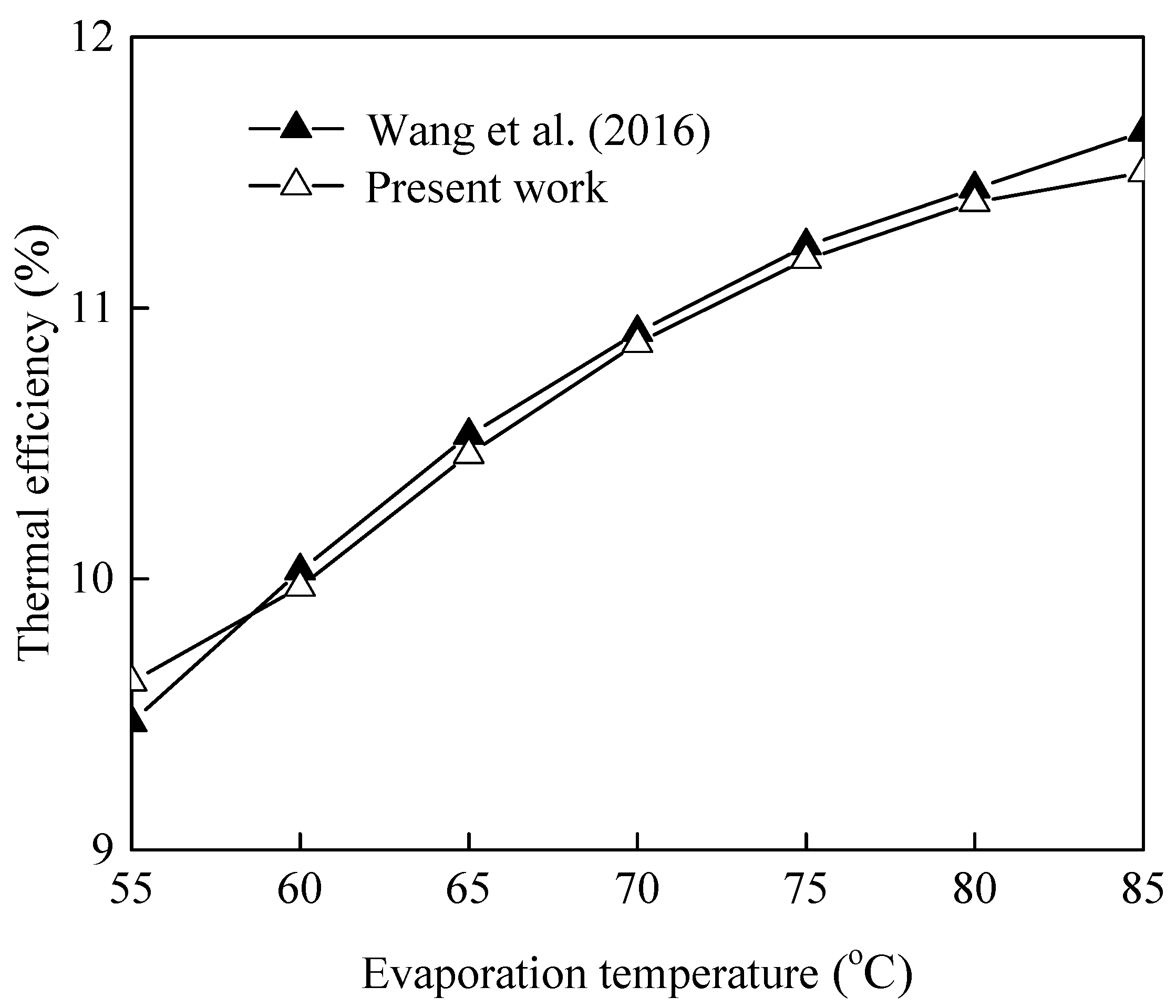
4. Model Verification

Comparison between the results of the present model and the ones in the literature was conducted to demonstrate its accuracy. The comparison under the same input operational conditions and working fluid is presented in Figure 2, from which it can be observed that the numerical prediction is close to the referenced data. Only small differences exist between the results; indeed, the largest relative error of thermal efficiency was lower than 1.30%. It indicates a good agreement between the present model and ref. [14].

5. Results and Discussion

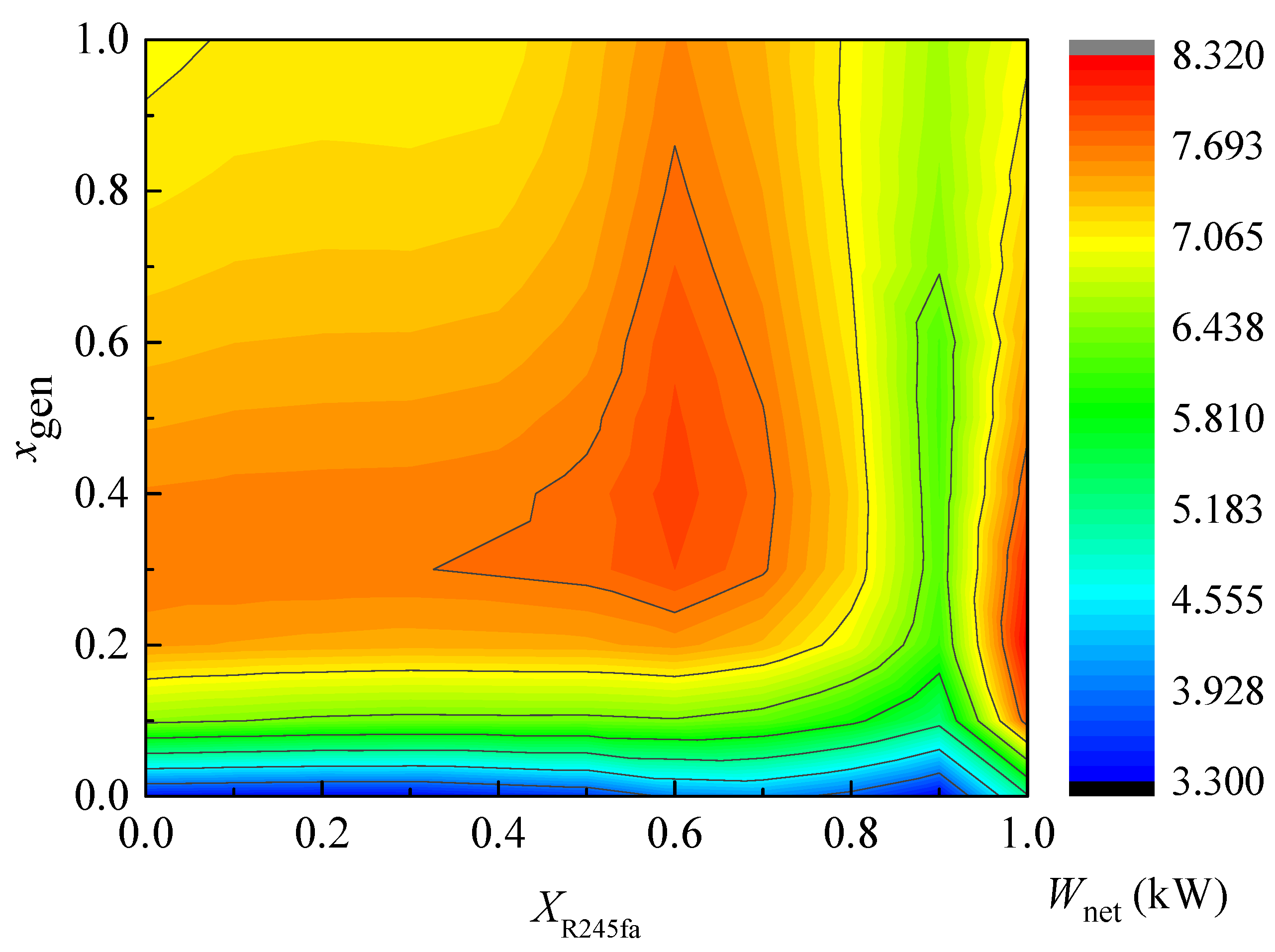
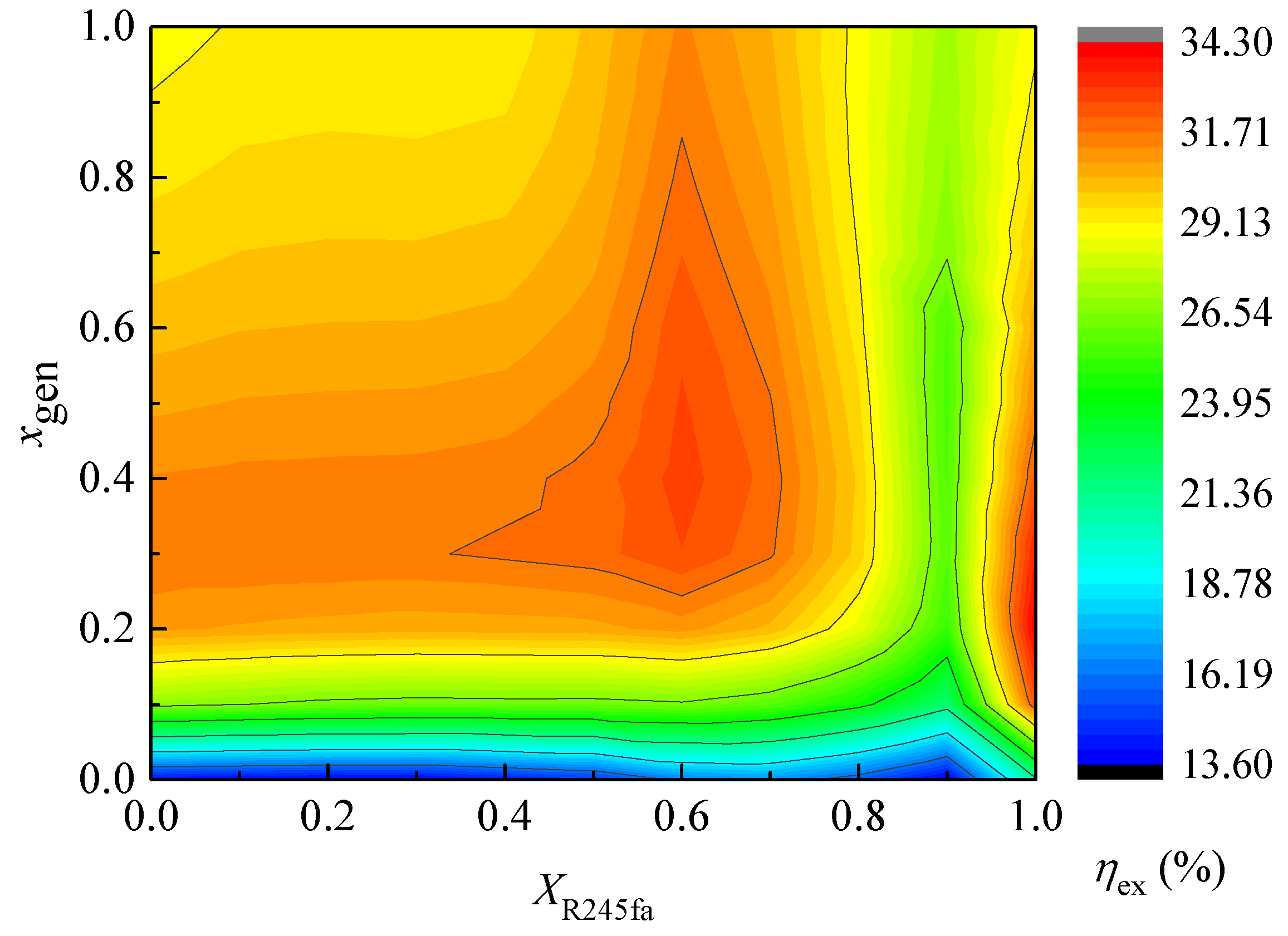
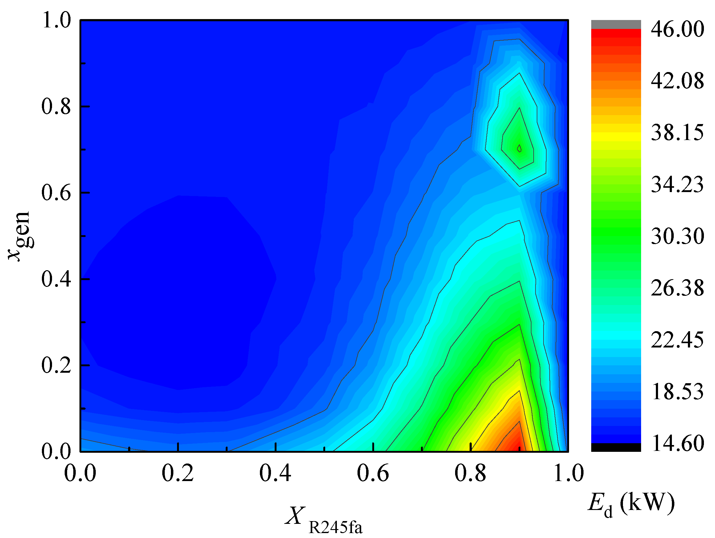
5.1. Synergy Optimization of R245fa Mass Fraction and Dryness

The largest difference between the ORC and the BFC is the working fluid dryness at the evaporator outlet. One of the key issues of geothermal power generation using zeotropic mixtures is the design of composition mass fraction. The input parameters for the synergy optimization of R245fa mass fraction and dryness at the evaporator outlet are listed in Table 1. Based on the energy analysis model, the influences of R245fa mass fraction (XR245fa) and zeotropic mixture dryness at the evaporator outlet (xgen) on the net power output (Wnet), thermal efficiency (ηth), exergy efficiency (ηex) and exergy destruction (Ed) are illustrated in Figure 3, Figure 4, Figure 5 and Figure 6. As can be seen, the net power output, thermal efficiency and exergy efficiency presented similar variation trends. There exists an approximate triangular region in the central zones of Figure 3, Figure 4 and Figure 5, at which the BFC yielded the best thermodynamic performance, i.e., higher net power output, thermal efficiency and exergy efficiency. The optimal ranges of R245fa mass fraction and zeotropic mixture dryness at the evaporator outlet were 0.30~0.70 and 0.30~0.80, at which the flammability of the zeotropic mixtures was suppressed. From Figure 6, the exergy destruction firstly increased and then decreased with the rising R245fa mass fraction. While in the low R245fa mass fraction ranges (0–0.50), the zeotropic mixture dryness at the evaporator outlet had weaker influence on the exergy destruction. To achieve the minimum exergy destruction, the optimal ranges of R245fa mass fraction and zeotropic mixture dryness at the evaporator outlet were 0.25~0.50 and 0.40~0.60. It also can be seen that when the R245fa mass fraction was near 1, the BFC also yielded better thermodynamic performance. Nevertheless, the zeotropic mixture dryness stayed in a narrow range, which will bring an enormous challenge to the BFC system’s steady operation. Comprehensively, considering the thermodynamic performance, the optimal ranges of R245fa mass fraction and zeotropic mixture dryness at the evaporator outlet were 0.30~0.50 and 0.40~0.60. The R245/R600a mixture BFC system presented better thermodynamic performance in comparison with that of pure working fluid. The main reason is that the temperature matching between working fluid and heat source/heat sink can be improved by employing R245/R600a mixtures.

5.2. Conventional Exergy Analysis

Based on BFC system’s energy analysis above, the R245fa mass fraction and zeotropic mixture dryness at the evaporator outlet were set to be 0.40 and 0.50, respectively, to facilitate the following analysis. The exergy destruction distribution of each component in the BFC is depicted in Figure 7. As can be observed, the maximum exergy destruction occurred in the condenser (4.02 kW), accounting for 26.41% of the total exergy destruction. This indicated that the condenser should be given the first priority for optimization. The exergy destructions of the expander, evaporator and flashing tank were 3.87, 2.94 and 2.699 kW, accounting for 25.40%, 19.32% and 17.73% of the total exergy destruction, respectively. The exergy destructions of the preheater, high-pressure pump and low-pressure pump were 1.01, 0.40 and 0.28 kW, respectively. Moreover, the sum of the three exergy destructions accounted for 11.1% of the total exergy destruction, which can be ignored. The exergy destruction in the heat exchangers, including the preheater, evaporator and condenser accounted for 52.40% of the total exergy destruction. A great amount of energy quality is lost, or there is larger destruction rate in the heat exchanger, because huge energy with high temperature (high quality) is transferred to the working fluid/cooling water at low temperature (low quality) under an irreversible process. As a consequence, in order to cut down the total exergy destruction for improving the exergy efficiency, more attention should be paid to the heat exchanger’s performance optimization.

5.3. Advanced Exergy Analysis

On the basis of the results derived from conventional exergy analysis, advanced exergy analysis was conducted to reveal the realistic improvement potential. For splitting exergy destruction into unavoidable and avoidable exergy destruction, the unavoidable operating condition of each component needs to be set. The main assumptions for real (actual operating conditions used for conventional analysis), unavoidable (with extremely high efficiency) and theoretical (theoretical maximum efficiency used to simulate the theoretical cycle) operating conditions of the components are listed in Table 3.
Under the operating conditions listed in Table 3, the state point parameters for real, unavoidable and theoretical operating conditions are listed in Table 4, Table 5 and Table 6. As can be seen, the net power output of theoretical operating condition was 92.8% and 7.08% higher than those of real and unavoidable operating conditions. The thermal efficiency of theoretical operating condition was 68.63% and 6.32% higher than those of real and unavoidable operating conditions. The exergy efficiency of theoretical operating condition was 78.16% and 6.64% higher than those of real and unavoidable operating conditions.
In comparison with conventional exergy analysis, the advanced exergy analysis further detailed the system exergy destruction and clarified the optimization direction. The avoidable/unavoidable exergy destruction of each component is illustrated in Figure 8. For writing convenience, evaporator, expander, flashing tank, condenser, low-pressure pump, high-pressure pump and preheater are abbreviated as “Eva”, “Exp”, “FT”, “Con”, “LPP”, “HPP” and “Pre”, respectively. It is worth mentioning that the avoidable part of exergy destruction can only be controlled. It can be seen that the avoidable and unavoidable exergy destructions of the expander were 3.387 and 0.4878 kW, respectively. The avoidable exergy destruction of the expander was the largest among all the components due to the occurrence of the expansion depressurization process, which is an intensely irreversible process. The avoidable exergy destruction of the expander accounted for 87.6% of the total exergy destruction of the expander. That is to say, most of the expander’s exergy destruction can be avoidable. The avoidable and unavoidable exergy destructions of the condenser were 2.565 and 1.459 kW, respectively. About 63.7% of the condenser exergy destruction can be avoidable. The avoidable and unavoidable exergy destructions of the evaporator were 1.148 and 1.790 kW. About 39.1% of the evaporator exergy destruction can be avoidable. The avoidable and unavoidable exergy destructions of the preheater were 0.363 and 0.646 kW. About 36.0% of the evaporator exergy destruction can be avoidable. Both the low-pressure pump and high-pressure pump exergy destructions were very small, and most of them were unavoidable. All the flashing tank exergy destruction was unavoidable. To sum up, the expander should draw the most attention, followed by condenser, evaporator, preheater, high-pressure pump and low-pressure pump. If there is only unavoidable exergy destruction in the BFC system, the total system exergy destruction can be reduced from 15.214 to 7.813 kW. The results from the conventional exergy analysis indicated that the condenser should be firstly optimized, followed by expander and evaporator, which is contradictory to that of the advanced exergy analysis. The comparison of component improvement priority between conventional and advanced exergy method presents a large difference due mainly to the different criteria. Furthermore, conclusions can be drawn that the engineers should focus on the avoidable exergy destruction rather than on the total exergy destruction.
The exogenous/endogenous exergy destruction of each component is displayed in Figure 9. As can be seen, for any component of the BFC system, endogenous exergy destruction accounted for a large proportion of the total exergy destruction. It indicates that the exergy destruction of the BFC is mainly caused by the irreversibilities of the components themselves rather than their interactions. Thus, it can be concluded that the interconnections between the system components are incompact.
Therefore, the improvement of each component should be put in the first place when system optimization is required. The interdependencies among system components can be positive or negative, which could be caused by mass flow change or thermodynamic property variation of working fluid through the specific component owing to the introduction of additional irreversibilities. The exogenous exergy destructions of the low-pressure pump, expander and condenser are all negative values, which is the result of differences in mass flow between endogenous and real operating conditions. That is to say, the endogenous exergy destruction is greater than the real exergy destruction. For the three components, performance improvement of other components not only cannot reduce the exergy reduction but it also increases it. The increase in expander isentropic efficiency is the only useful measurement to reduce its exergy reduction.
What is more, the advanced exergy analysis also has some limitations. Firstly, the advanced exergy analysis possesses definite subjectivity associated with the avoidable exergy destruction calculation and the definition of both theoretical and unavoidable operating conditions. Secondly, a large number of calculations is required to obtain the avoidable-endogenous, avoidable-exogenous, unavoidable-endogenous and the unavoidable-exogenous exergy destruction.

6. Conclusions

In present study, a BFC using R245fa/R600a zeotropic mixtures is proposed. Taking into consideration the thermodynamic performance and working fluids’ flammability, the optimal R245fa mass fraction and zeotropic mixture dryness at the evaporator outlet introduced by the ORC system’s modification are investigated. The energy analysis, conventional exergy analysis and advanced exergy analysis are conducted in sequence. The significant conclusions are summarized as follows:
(1)
To suppress the flammability of the R245fa/R600a zeotropic mixtures, the R245fa mass fraction should be larger than 0.239. There exists a certain R245fa mass fraction range, at which the zeotropic mixture BFC system exhibits better performance than that of pure working fluid, with comprehensive consideration of net power output, thermal efficiency, exergy efficiency and exergy destruction. The recommended ranges of R245fa mass fraction and zeotropic mixture dryness at the evaporator outlet are 0.30~0.50 and 0.40~0.60.
(2)
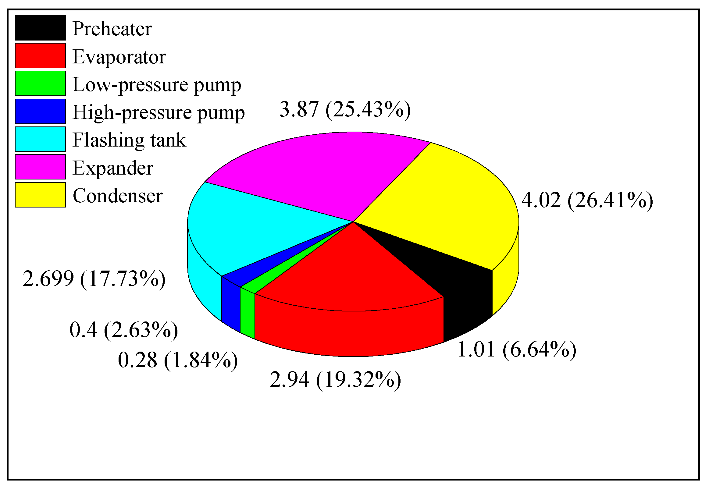
By conventional exergy analysis, the maximum exergy destruction occurred in the condenser, followed by the expander, evaporator, flashing tank, preheater, high-pressure pump and low-pressure pump. The exergy destructions of the preheater, high-pressure pump and low-pressure pump can be ignored. The condenser should be given the first priority. The exergy destruction in the heat exchangers accounts for 52.40% of the total exergy destruction.
(3)
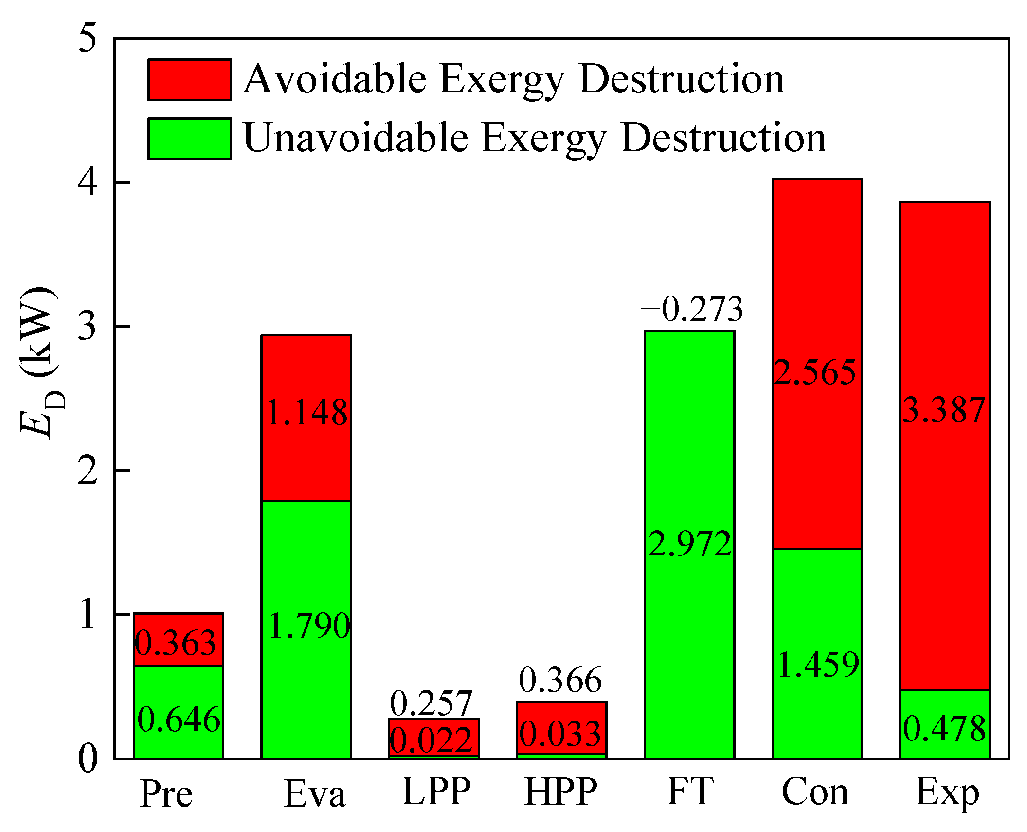
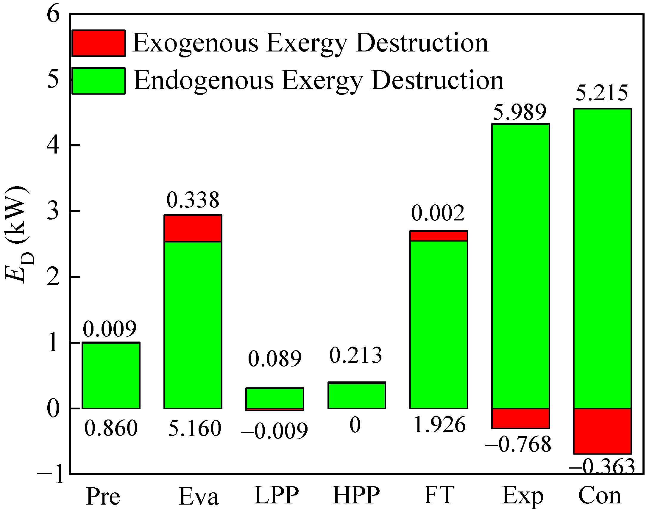
By advanced exergy analysis, the priority should be given to the expander because of its large avoidable exergy destruction exergy destruction, followed by the condenser and evaporator. From the viewpoint of avoidability, about 48.6% of total system exergy destruction can be avoidable. The optimization sequence of BFC components deduced from the conventional and advanced methods is quite different. The interconnections among system components are not very strong, owing to small exogenous exergy destructions. Taking into account the interrelationships between components and the technical limitations of system components, the advanced exergy analysis could diagnose the detailed interactions among components of the BFC system and facilitate an exergoeconomic optimization. It clarifies the advantage of the advanced exergy analysis compared with the conventional exergy analysis.
In summary, although the conclusions are different, the conventional exergy analysis results are strongly supplemented by the advanced exergy analysis results. The advanced exergy analysis could diagnose the detailed interactions among components, improve the accuracy of exergy analysis and facilitate an exergoeconomic optimization. However, the present analysis only provides the direction of component optimization for the optimal design. In the future work, more attention will be paid to the definition of both the theoretical and unavoidable operating conditions to strengthen the objectivity of the results by the advanced exergy analysis. Furthermore, the advanced exergoeconomic cost analysis of the BFC will be conducted based on the advanced exergy analysis and economic principles, in order to provide more information that is useful to the design and operation of a cost-effective BFC system.

Author Contributions

Conceptualization and methodology: Y.Z.; software and formal analysis: B.D.; validation, supervision, writing—review and editing and visualization: S.C.; validation and data curation: J.Z.; formal analysis: Z.G.; conceptualization, methodology and writing—original draft: L.W. All authors have read and agreed to the published version of the manuscript.

Funding

The authors gratefully acknowledge the financial support provided by the Natural Science Foundation of Guangdong Province (No. 2021A1515011763), the Science and Technology Plan Project of Guangzhou (No. 202102020301) and the China Postdoctoral Science Foundation (No. 2020M681799).

Institutional Review Board Statement

Not applicable.

Informed Consent Statement

Informed consent was obtained from all subjects involved in the study.

Data Availability Statement

The datasets used and/or analyzed during the current study are available from the corresponding author on reasonable request.

Acknowledgments

We express our gratitude to C.J. Li for technical support for data analysis.

Conflicts of Interest

The authors declare that they have no competing interests.

Abbreviations

Cminminimum inerting volume concentration (%)
cpspecific heat capacity (kJ/kg·K−1)
Cststoichiometric concentration (%)
especific exergy, (J/kg)
Edexergy destruction (W)
EFinput exergy (W)
E D , k AV avoidable exergy destruction (W)
E D , k AV , EN avoidable-endogenous exergy destruction (W)
E D , k AV , EX avoidable-exodogenous exergy destruction (W)
E D , k EN endogenous exergy destruction (W)
E D , k EX exodogenous exergy destruction (W)
E D , k UN unavoidable exergy destruction (W)
E D , k UN , EN unavoidable-endogenous exergy destruction (W)
E D , k UN , EX unavoidable-exodogenous exergy destruction (W)
Epoutput exergy (W)
hspecific enthalpy (kJ/kg)
h0specific enthalpy under ambient state (kJ/kg)
mmass flow rate (kg/s)
MR245famolar mass of R245fa (kg/kmol)
MR600amolar mass of R600a (kg/kmol)
Qheat transfer rate (kW)
s0specific exergy under ambient state (kJ/kg)
ttemperature (°C)
T0ambient temperature (°C)
Xmass fraction of zeotropic mixtures (%)
XminR245fa mass fraction of zeotropic mixtures (%)
xdryness
vvelocity, m/s;
Wpower/work (kW)
Greek
ηefficiency
Φsuppression coefficient
Subscripts
0ambient condition
1, 2, …,12 state points
AVavoidable
cfcooling water
concondenser
ENendogenous
EXexgenous
eva evaporator
exexergy
expexpander
FTflash tank
hfgeofluid
HPPhigh-pressure pump
ininlet
LPPlow-pressure pump
maxmaximum
netnet
ththermal
outoutlet
prepreheater
sisentropic
UNunavoidable
wfworking fluid
Acronyms
BFCbinary-flashing cycle
GWPglobal warming potential
LEClevelized energy cost
ODPozone depletion potential
ORCorganic Rankine cycle

References

  1. Nadimi, R.; Tokimatsu, K. Energy use analysis in the presence of quality of life, poverty, health, and carbon dioxide emissions. Energy 2018, 153, 671–684. [Google Scholar] [CrossRef]
  2. Huang, F.; Zheng, J.; Baleynaud, J.M.; Lu, J. Heat recovery potentials and technologies in industrial zones. J. Energy Inst. 2017, 90, 951–961. [Google Scholar] [CrossRef]
  3. Nguyen, K.H.; Kakinaka, M. Renewable energy consumption, carbon emissions, and development stages: Some evidence from panel cointegration analysis. Renew. Energy 2019, 132, 1049–1057. [Google Scholar] [CrossRef]
  4. Davidson, M.; Karplus, V.J.; Zhang, D.; Zhang, X. Policies and Institutions to Support Carbon Neutrality in China by 2060. Econ. Energy Environ. Policy 2021, 10, 7–25. [Google Scholar] [CrossRef]
  5. Irfan, M.; Elavarasan, R.M.; Hao, Y.; Feng, M.; Sailan, D. An assessment of consumers’ willingness to utilize solar energy in China: End-users’ perspective. J. Clean. Prod. 2021, 292, 126008. [Google Scholar] [CrossRef]
  6. Magazzino, C.; Mele, M.; Schneider, N. A machine learning approach on the relationship among solar and wind energy production, coal consumption, GDP, and CO2 emissions. Renew. Energy 2021, 167, 99–115. [Google Scholar] [CrossRef]
  7. Kong, Y.; Pang, Z.; Shao, H.; Hu, S.; Kolditz, O. Recent studies on hydrothermal systems in China: A review. Geotherm. Energy 2014, 2, 19. [Google Scholar] [CrossRef] [Green Version]
  8. Zhang, L.X.; Pang, M.Y.; Han, J.; Li, Y.Y.; Wang, C.B. Geothermal power in China: Development and performance evaluation. Renew. Sustain. Energy Rev. 2019, 116, 109431. [Google Scholar] [CrossRef]
  9. Özcan, Z.; Ekici, Ö. A novel working fluid selection and waste heat recovery by an exergoeconomic approach for a geothermally sourced ORC system. Geothermics 2021, 95, 102151. [Google Scholar] [CrossRef]
  10. Michaelides, E.E.; Scott, G.J. A binary-flashing geothermal power plant. Energy 1984, 9, 323–331. [Google Scholar] [CrossRef]
  11. Shi, H.; Michaelides, E.E. Binary dual-flashing geothermal power plants. Int. J. Energy Res. 1989, 13, 127–135. [Google Scholar] [CrossRef]
  12. Yuan, Z.; Michaelides, E.E. Binary-flashing geothermal power plants. J. Energy 1993, 115, 232–236. [Google Scholar] [CrossRef]
  13. Michaelides, E. Future directions and cycles for electricity production from geothermal resources. Energy Convers. Manag. 2016, 107, 3–9. [Google Scholar] [CrossRef]
  14. Wang, Y.X.; Wang, L.B.; Li, H.S.; Bu, X.B. Thermodynamic calculation and optimization of geothermal power generation in Ganzi. J. Harbin Eng. Univ. 2016, 37, 873–877. (In Chinese) [Google Scholar]
  15. Mosaffa, A.H.; Zareei, A. Proposal and thermoeconomic analysis of geothermal flash binary power plants utilizing different types of organic flash cycle. Geothermics 2018, 72, 47–63. [Google Scholar] [CrossRef]
  16. Edrisi, B.H.; Michaelides, E.E. Effect of the working fluid on the optimum work of binary-flashing geothermal power plants. Energy 2013, 50, 389–394. [Google Scholar] [CrossRef]
  17. Wang, L.; Bu, X.; Li, H. Investigation on geothermal binary-flashing cycle employing zeotropic mixtures as working fluids. Geothermal. Energy 2019, 7, 36. [Google Scholar] [CrossRef] [Green Version]
  18. Liu, X.; Li, H.S.; Bu, X.B.; Wang, L.; Xie, N.; Zeng, J. Performance characteristics and working fluid selection for low-temperature binary flashing cycle. Appl. Therm. Eng. 2018, 141, 51–60. [Google Scholar] [CrossRef]
  19. Wang, L.; Li, H.; Bu, X. Multi-objective optimization of Binary Flashing Cycle (BFC) driven by geothermal energy. Appl. Therm. Eng. 2020, 166, 114693. [Google Scholar] [CrossRef]
  20. Wang, L.; Li, H.; Bu, X. Thermo-economic investigation of binary flashing cycle for enhanced geothermal system. Geothermics 2021, 89, 101951. [Google Scholar] [CrossRef]
  21. Tsatsaronis, G. Strengths and limitations of exergy analysis. In Thermodynamic Optimization of Complex Energy Systems; Bejan, A., Mamut, E., Eds.; Kluwer Academic Publishers: Dordrecht, The Netherlands, 1999; pp. 93–100. [Google Scholar]
  22. Tsatsaronis, G.; Moung-Ho, P. On avoidable and unavoidable exergy destructions and investment costs in thermal systems. Energy Convers. Manag. 2002, 43, 1259–1270. [Google Scholar]
  23. Dai, B.; Zhu, K.; Wang, Y.; Sun, Z.; Liu, Z. Evaluation of organic Rankine cycle by using hydrocarbons as working fluids: Advanced exergy and advanced exergoeconomic analyses. Energy Convers. Manag. 2019, 197, 111876. [Google Scholar] [CrossRef]
  24. Nami, H.; Nemati, A.; Fard, F.J. Conventional and advanced exergy analyses of a geothermal driven dual fluid organic Rankine cycle (ORC). Appl. Therm. Eng. 2017, 122, 59–70. [Google Scholar] [CrossRef]
  25. Gökgedik, H.; Yürüsoy, M.; Keçebaş, A. Improvement potential of a real geothermal power plant using advanced exergy analysis. Energy 2016, 112, 254–263. [Google Scholar] [CrossRef]
  26. Wang, Z.; Xia, X.; Pan, H.; Zuo, Q.; Zhou, N.; Xie, B. Fluid selection and advanced exergy analysis of dual-loop ORC using zeotropic mixture. Appl. Therm. Eng. 2021, 185, 116423. [Google Scholar] [CrossRef]
  27. Liao, G.; Jiaqiang, E.; Zhang, F.; Chen, J.; Leng, E. Advanced exergy analysis for Organic Rankine Cycle-based layout to recover waste heat of flue gas. Appl. Energy 2020, 266, 114891. [Google Scholar] [CrossRef]
  28. Chen, J.; Zheng, X.; Guo, G.; Luo, X.; Chen, Y.; Yang, Z. A flexible and multi-functional organic Rankine cycle system: Preliminary experimental study and advanced exergy analysis. Energy Convers. Manag. 2019, 187, 339–355. [Google Scholar] [CrossRef]
  29. Montazerinejad, H.; Ahmadi, P.; Montazerinejad, Z. Advanced exergy, exergo-economic and exrgo-environmental analyses of a solar based trigeneration energy system. Appl. Therm. Eng. 2019, 152, 666–685. [Google Scholar] [CrossRef]
  30. Khosravi, H.; Salehi, G.R.; Azad, M.T. Design of structure and optimization of organic Rankine cycle for heat recovery from gas turbine: The use of 4E, advanced exergy and advanced exergoeconomic analysis. Appl. Therm. Eng. 2019, 147, 272–290. [Google Scholar] [CrossRef]
  31. Anvari, S.; Saray, R.K.; Bahlouli, K. Conventional and advanced exergetic and exergoeconomic analyses applied to a tri-generation cycle for heat, cold and power production. Energy 2015, 91, 925–939. [Google Scholar] [CrossRef]
  32. Ambriz-Díaz, V.M.; Rubio-Maya, C.; Ruiz-Casanova, E.; Martinez-Patino, J.; Pastor-Martínez, E. Advanced exergy and exergoeconomic analysis for a polygeneration plant operating in geothermal cascade. Energy Convers. Manag. 2020, 203, 112227. [Google Scholar] [CrossRef]
  33. Zhang, Y.; Liang, T.; Yang, C.; Zhang, X.; Yang, K. Advanced exergy analysis of an integrated energy storage system based on transcritical CO2 energy storage and Organic Rankine Cycle. Energy Convers. Manag. 2020, 216, 112938. [Google Scholar] [CrossRef]
  34. Yang, J.; Gao, L.; Ye, Z.; Hwang, Y.; Chen, J. Binary-objective optimization of latest low-GWP alternatives to R245fa for organic Rankine cycle application. Energy 2021, 217, 119336. [Google Scholar] [CrossRef]
  35. Feng, Y.; Hung, T.; Zhang, Y.; Li, B.; Yang, J.; Shi, Y. Performance comparison of low-grade ORCs (organic Rankine cycles) using R245fa, pentane and their mixtures based on the thermoeconomic multi-objective optimization and decision makings. Energy 2015, 93, 2018–2029. [Google Scholar] [CrossRef]
  36. Lemmon, E.W.; Huber, M.L.; McLinden, M.O. NIST Standard Reference Database 23: Reference Fluid Thermodynamic and Transport Properties-REFPROP; Version 9.1, Standard Reference Data Program; National Institute of Standards and Technology: Gaithersburg, MD, USA, 2013.
  37. Bai, T.; Yu, J.; Yan, G. Advanced exergy analysis on a modified auto-cascade freezer cycle with an ejector. Energy 2016, 113, 385–398. [Google Scholar] [CrossRef]
  38. Hu, Y. Advanced Exergy Analysis for a Solar Double Stage Absorption Chiller; Carnegie Mellon University: Pittsburgh, PA, USA, 2012. [Google Scholar]
  39. Lemort, V.; Quoilin, S.; Cuevas, C.; Lebrun, J. Testing and modeling a scroll expander integrated into an organic Rankine cycle. Appl. Therm. Eng. 2009, 29, 3094–3102. [Google Scholar] [CrossRef] [Green Version]
  40. Fallah, M.; Mahmoudi, S.M.S.; Yari, M.; Ghiasi, R.A. Advanced exergy analysis of the Kalina cycle applied for low temperature enhanced geothermal system. Energy Convers. Manag. 2016, 108, 190–201. [Google Scholar] [CrossRef]
  41. Imran, M.; Usman, M.; Park, B.S.; Kim, H.-J.; Lee, D.-H. Multi-objective optimization of evaporator of organic Rankine cycle (ORC) for low temperature geothermal heat source. Appl. Therm. Eng. 2015, 80, 1–9. [Google Scholar] [CrossRef]
Figure 1. Schematic layout of BFC.
Energies 15 03487 g001
Figure 2. Comparison of simulation results between the present work and Ref. [14].
Energies 15 03487 g002
Figure 3. Variations of Wnet with xgen and XR245fa.
Energies 15 03487 g003
Figure 4. Variations of ηth with xgen and XR245fa.
Energies 15 03487 g004
Figure 5. Variations of ηex with xgen and XR245fa.
Energies 15 03487 g005
Figure 6. Variations of Ed with xgen and XR245fa.
Energies 15 03487 g006
Figure 7. Exergy destruction of BFC system components.
Energies 15 03487 g007
Figure 8. Avoidable/unavoidable exergy destruction of each component.
Energies 15 03487 g008
Figure 9. Exogenous/endogenous exergy destruction of each component.
Energies 15 03487 g009
Table 1. Thermo-physical properties of R245fa and R600a.
FluidMolecular Mass (g/mol)Critical Temperature (°C)ODPGWPFlammability aToxicity c
R245fa134.05154.00103032
R600a58.12134.70331
a Flammability is graded as four levels ranging from 0 to 3, in which 0 denotes nonflammability. c Toxicity is graded as seven levels ranging from 0 to 6, in which 0 denotes nontoxicity.
Table 2. Operating conditions and parameters.
ParametersValues
Inlet temperature of geobrine (°C)90
Inlet temperature of cooling water (°C)20
Degree of subcooling (°C)3
Pinch point temperature of heat exchanger (°C)5
Isentropic efficiency of expander (%)70
Isentropic efficiency of pump (%)60
Ambient temperature (°C)20
Ambient pressure (kPa)101.325
Table 3. Assumptions for the real, unavoidable and theoretical operating conditions.
ComponentParameterRealUnavoidableTheoretical
Heat exchangerPinch point temperature difference (°C)5 [37]0.3 [38]0
ExpanderIsentropic efficiency0.7 [39]0.95 [40]1
Low-pressure pumpIsentropic efficiency0.6 [41]0.95 [40]1
High-pressure pumpIsentropic efficiency0.6 [41]0.95 [40]1
Flashing tankIsentropic efficiencyIsenthalpic0.951
Table 4. State point parameters for real operating conditions.
State PointTemperature (°C)Pressure
(kPa)
Enthalpy
(kJ/kg)
Entropy
(kJ/kg·K−1)
Mass Flow Rate (kg/s)DrynessR245fa Mass Fraction
170.005880.435368.7401.5792.16320.1410.600
270.005880.435546.1602.0970.305910.587
339.716299.692522.2702.1140.6221.0530.581
427.000299.692259.1901.2470.62200.581
527.511880.435260.3401.2480.622Subcooling0.581
650.346880.435302.6101.3840.62200.581
750.352880.435301.2101.3791.5413Subcooling0.608
850.346880.435301.6101.3802.1632Subcooling0.600
970.000880.435339.6801.4942.163200.600
1070.005880.435339.5201.4941.857300.602
1150.003531.511529.8202.0880.316110.576
1250.003531.511300.4901.3781.541300.608
Wnet = 7.876 kW; ηth = 4.590%; ηex = 32%
Table 5. State point parameters for unavoidable operating conditions.
State PointTemperature
(°C)
Pressure
(kPa)
Enthalpy
(kJ/kg)
Entropy
(kJ/kg·K−1)
Mass Flow Rate (kg/s)DrynessR245fa Mass Fraction
170.007880.435377.8401.6052.1630.1860.600
270.007880.435546.0402.0960.40210.587
336.068299.646516.9902.0970.6901.0320.583
427.000299.646259.1601.2470.69000.583
527.276880.435259.8801.2470.690Subcooling0.583
650.207880.435302.2701.3830.69000.583
750.212880.435300.9201.3781.473Subcooling0.608
850.207880.435301.3501.3792.163Subcooling0.600
970.000880.435339.6801.4942.16300.600
1070.007880.435339.4601.4941.76100.603
1150.004531.495529.7402.0880.28810.576
1250.004531.495300.4601.3781.47300.608
Wnet = 14.179 kW; ηth = 7.280%; ηex = 53.460%
Table 6. State point parameters for theoretical operating conditions.
State PointTemperature (°C)Pressure
(kPa)
Enthalpy
(kJ/kg)
Entropy
(kJ/kg·K−1)
Mass Flow Rate (kg/s)DrynessR245fa Mass Fraction
170.0072880.4352378.421.60712.16290.18860.6
270.0072880.4352546.032.09610.407910.587
335.2434299.6433515.852.09280.69441.02750.5825
427299.6433259.161.24650.694400.5825
527.2554880.4352259.851.24650.6944Subcooling0.5825
650.1945880.4352302.241.38250.694400.5825
750.1999880.4352300.891.37751.4685Subcooling0.6083
850.1945880.4352301.321.37912.1629Subcooling0.6
970880.4352339.681.49422.162900.6
1070.0072880.4352339.461.49351.75500.603
1150.0036531.4933529.732.08810.286510.5761
1250.0036531.4933300.461.37751.468500.6083
Wnet = 15.183 kW; ηth = 7.740%; ηex = 57.010%
Publisher’s Note: MDPI stays neutral with regard to jurisdictional claims in published maps and institutional affiliations.

