Article

Directional Bending Performance of 4-Leg Jacket Substructure Supporting a 3MW Offshore Wind Turbine

1
Institute of Offshore Wind Energy, Kunsan National University, 558 Daehak-ro, Gunsan-City 54150, Jeollabuk-do, Korea
2
Faculty of Technology and Technique, Quy Nhon University, Binh Dinh 55100, Vietnam
3
Department of Mechanical Engineering, Kunsan National University, 558 Daehak-ro, Gunsan-City 54150, Jeollabuk-do, Korea
*
Author to whom correspondence should be addressed.
Energies 2021, 14(9), 2725; https://doi.org/10.3390/en14092725
Submission received: 22 March 2021 / Revised: 21 April 2021 / Accepted: 29 April 2021 / Published: 10 May 2021
(This article belongs to the Section A3: Wind, Wave and Tidal Energy)

Abstract

:
A comprehensive investigation of the directional bending performance of a 4-leg jacket substructure, supporting a 3 MW offshore wind turbine, has been carried out in this study. The jacket substructure with a Pratt bracing system which is already installed in the southwest offshore wind farm in South Korea has been chosen as a reference support structure. A numerical model of the 3MW support structure (i.e., tower, transition piece, and jacket structure) is configured, and its structural performances are evaluated under the conditions of (1) extreme environmental loads (Env), (2) critical Design Load Cases (DLCs), and (3) a total of 288 combined load cases (CBs). For the case of Env (i.e., wind, wave, and current loads), loading directions varying from 0° to 360° at intervals of 15° are considered. The DLCs are provided from the 3 MW wind turbine manufacturer, in a 6 × 12 matrix format. The selected 4-leg jacket substructure in this study showed the smallest bending stiffness at the loading angles of 135° and 315° under the condition of Env, and at the loading angles between 105° and 150° under the CBs. From these results, critical bending directionality of the 4-leg jacket substructure is identified. This study also found that the effects of Env loads are not small compared to the total structural responses of the 4-leg jacket substructure which is supporting a 3 MW offshore wind turbine.

1. Introduction

Selecting a suitable substructure plays a significant role since it directly affects the overall finance of an offshore wind farm project. Various substructures (such as the gravity-based, monopile, and jacket), supporting offshore wind turbines (OWTs), have been developed mainly based on the design parameter of water depth [1]. For the ocean environmental conditions in South Korea, however, jacket substructure is currently known as the most popular solution because it is the most versatile design concept in this region [2,3,4,5].
Designing the jacket substructure is a complicated process due to complex dynamic interactions among the ocean environment, substructure layout, and soil condition under the sea water [2,3,4,5,6,7,8,9]. Among them, the ocean environment is one of the key design factors to select the type of substructure and its structural layouts. Several studies have been made to explore the effects of the ocean environment [3,4,7,10,11,12,13]. Shi et al. [3] investigated the effects of various structural parameters and ocean environmental conditions on the dynamic response of jacket substructures. In order to understand the effects of wave forces acting on the offshore support structures, Jeong et al. [7] executed an experimental study under various wave conditions. However, until now, no comprehensive investigations have been made to understand the effects of environmental loading directionality on the structural responses of the jacket substructure.
In order to increase the safety level of the jacket substructure, which is installed in the ocean, it is important to understand the critical bending direction, as well as the maximum bending resistance. A few studies have been made to investigate this aspect [10,14]. Chew et al. [14] conducted a parametric study to evaluate the sensitivity of environmental loading directionality on the dynamic performances of the jacket substructures, which have been developed in the IEA Task 30 OC4 project [15]. The same research process was also adopted to clarify the effects of incident wind/wave directions on the dynamic response of an NREL-5MW OWT substructure [10]. However, these previous studies have not covered some possible critical scenarios, such as two critical loads (i.e., ultimate design loads at the tower-substructure interface and extreme environmental loads) acting on the substructures simultaneously. In the above, the ultimate design loads are identical to the critical Design Load Cases (DLCs) written in the matrix format, which is explained later in this paper.
Hence, the objectives of this study are to address the technical gaps, which have not been particularly highlighted in the previous literature. The specific contributions are as follows:
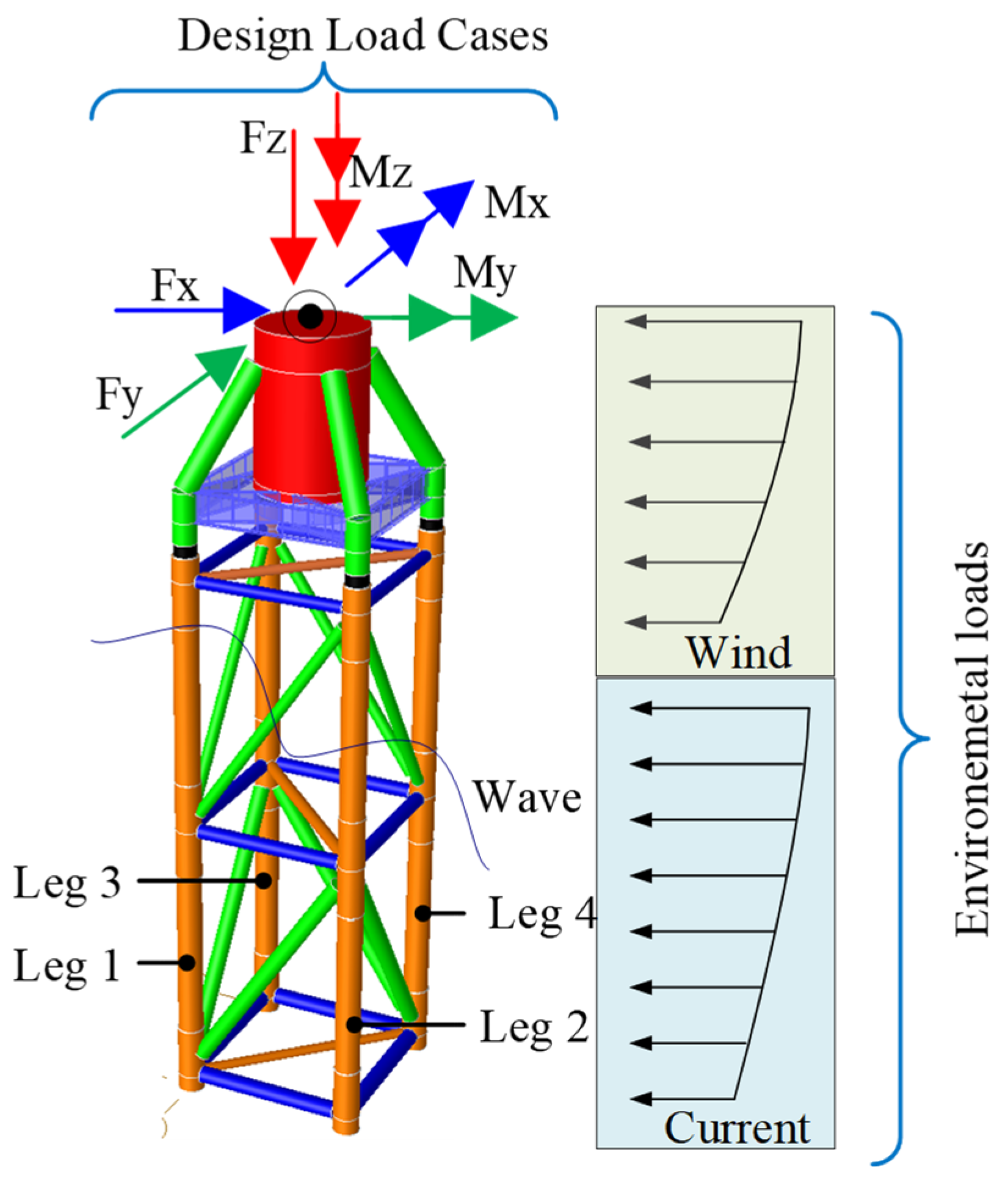
  • Assessment of structural responses of a 4-leg jacket substructure under extreme environmental loads (i.e., wind, wave, and current loading conditions);
  • Determination of critical bending direction of the 4-leg jacket substructure under various loading conditions;
  • Calculation of percentage contribution of the environmental load effects to the total structural response of the 4-leg jacket substructure supporting an OWT.

2. 3 MW 4-Leg Jacket Substructure Model

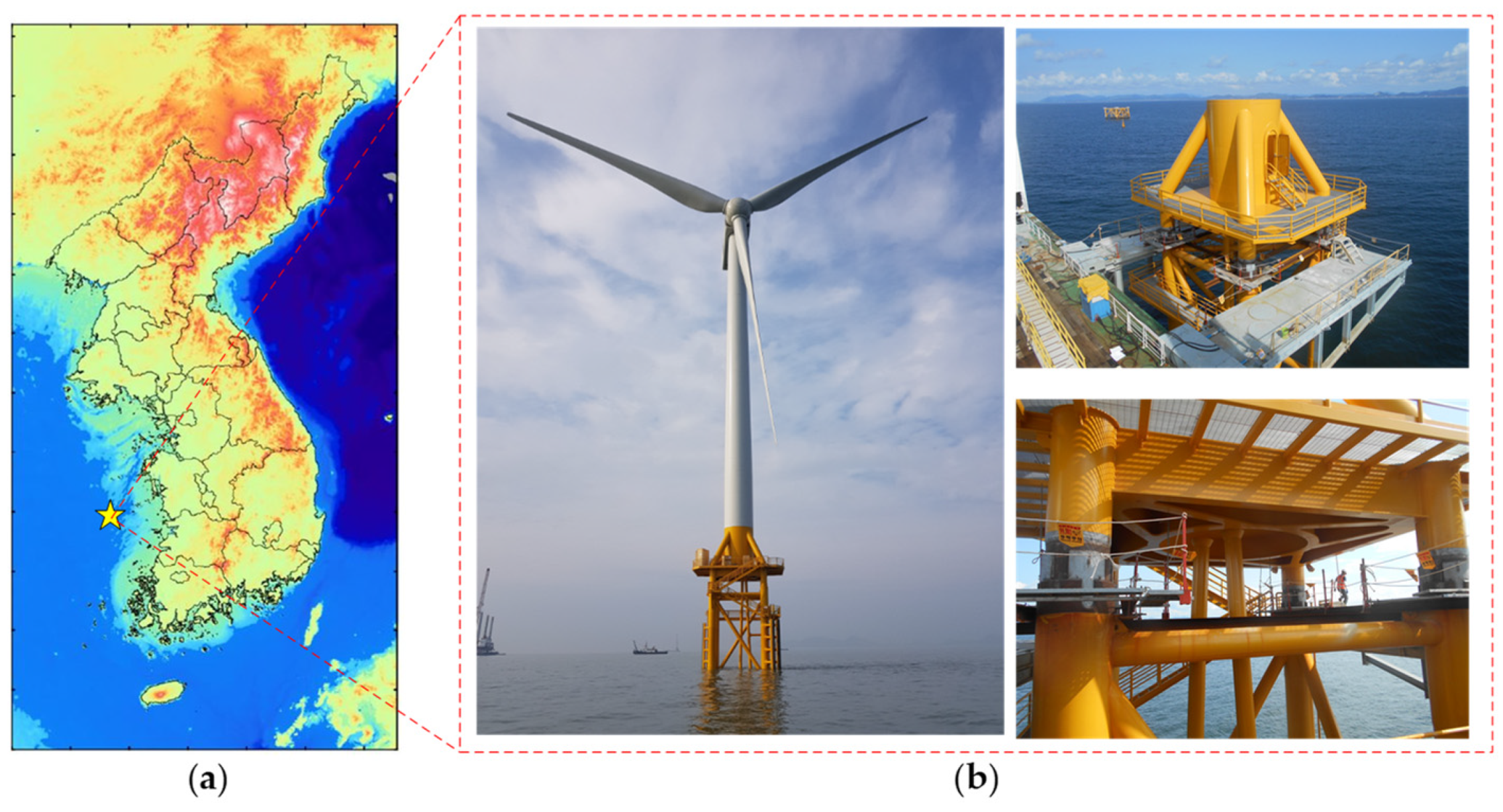
2.1. Configuration of the 4-Leg Jacket Substructure

A prototype of the 3MW offshore wind turbine (OWT) [16], which is installed in the southwest offshore wind farm in South Korea, is utilized in this study. The site location and overall configuration of the 3MW OWT are shown in Figure 1. The wind turbine is mounted on a 4-leg jacket substructure at the mean sea water level of around 14 m. The general specifications (i.e., geometrical and mechanical details) of the 3MW OWT reference model are summarized in Table 1. The wind tower has a height of 56.78 m above the jacket Transition Piece (TP) platform, and it is assembled by three steel tubular sections. The outer diameters at the bottom and top of the tower vary linearly from 450 cm to 307 cm, and the corresponding thicknesses reduce from 3.4 cm to 1.8 cm, respectively. Meanwhile, the total height of the 4-leg jacket substructure is 32.47 m, and it consists of a TP and a jacket structure. In order to provide the required stiffness of the jacket substructure, a Pratt system is selected for the braces.

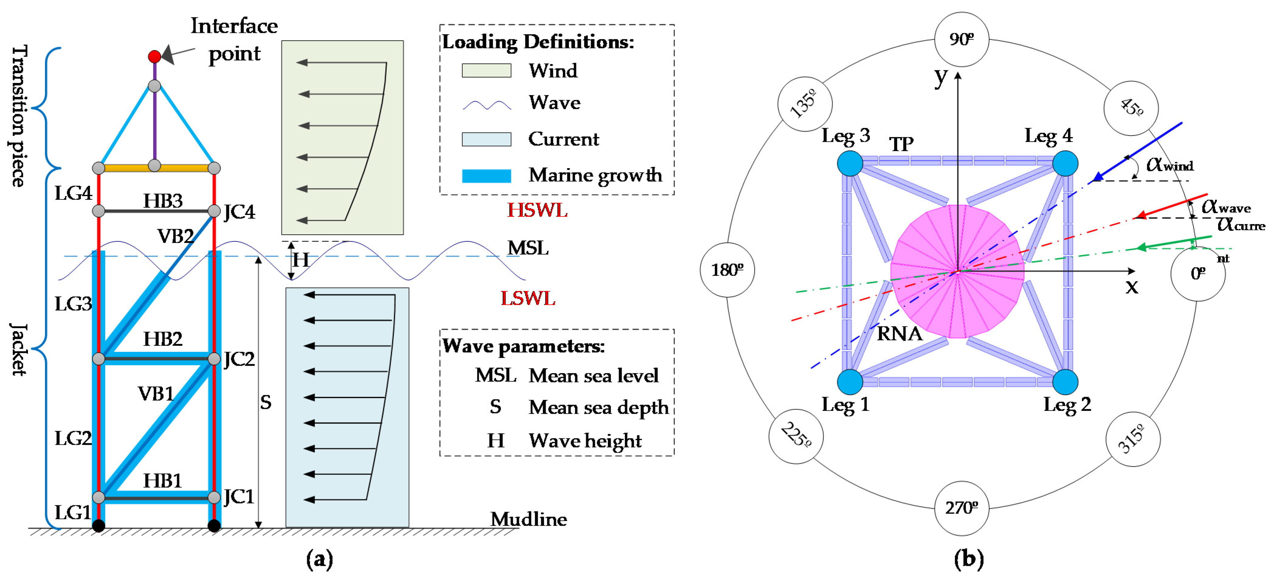
2.2. Environmental Conditions

The environmental loads acting on the jacket substructure can be classified into two types: aerodynamic loads and hydrodynamic loads. These loads are known as significant design loads for the OWT substructures. Kim et al. [17] conducted a feasibility study to select optimal sites for the offshore wind generation around the Korean peninsula. Results indicated that optimal regions for the offshore wind farm are widely distributed in the West Sea, where the sea water depth is limited up to 20 m over a 10 km distance from the coastline. Thus, this region has been chosen as a reference site to evaluate the structural responses of the 4-leg jacket substructure for 3MW OWT.
In this study, the critical scenario of the offshore site is selected based on the wind and wave rose maps obtained from metocean analyses [16]. The wind rose map describes the wind speed corresponding to the wind direction, while the wave rose map describes the wave height corresponding to the wave direction. A summarization of the environmental conditions (i.e., wind, wave, and current) is given in Table 2.

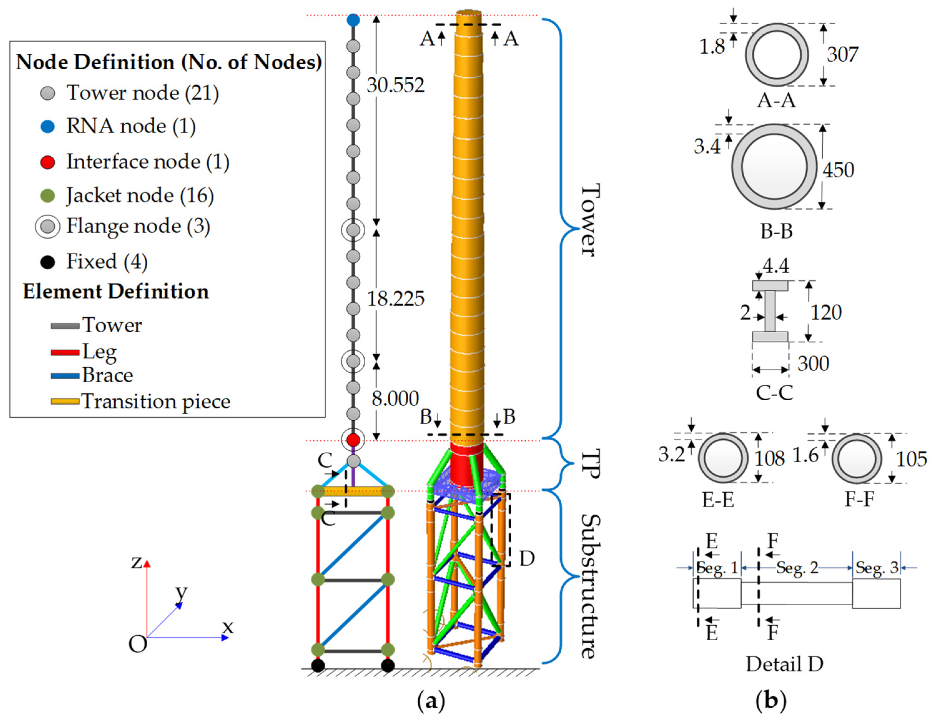
3. Modeling of the Support Structure

The numerical model of the 3MW OWT support structure is developed using the specialized software program SACS (Structural Analysis Computer System) [18]. An overview of the support structure used in this study is illustrated in Figure 2. The numerical model consists of the tower, Transition Piece (TP), and jacket structure. More detailed explanations of each component are depicted in the next sub-sections.

3.1. Tower

The tower is modeled using the beam elements, which allow the linear behavior for the forces and cubic behavior for the moments. The tubular sections are utilized to configure the tower, with the relevant properties displayed in Figure 2b. Due to the complexity of its configuration, geometrical details of the Rotor Nacelle Assembly (RNA) are neglected in the numerical model. Instead, the 3MW RNA is assumed as a mass on the tower with a designed eccentricity. Additionally, the tower flange is considered as a lumped mass at the designed location following the tower (Figure 2a).

3.2. Transition Piece (TP)

TP is the structural component transferring the loads from the tower to the jacket structure. The TP is assembled by H-section beams and tubular tubes (Figure 2b). The TP is configured using shell elements, except the cylinder at the center of the platform deck which is modeled using the Euler-Bernoulli beam elements. Since the beam elements are adopted to simulate the cylinder, the access door in the cylinder is neglected in the analysis model.

3.3. Jacket Structure

Similar to the tower, the Euler-Bernoulli beam elements are used to model the 4-leg jacket structure. Sections of the jacket legs and brace members are modeled as tubular sections. In order to accurately capture the structural behavior, segmented members are configured for the jacket legs, as illustrated in Figure 2b. Each segment is divided into three sections which correspond to their properties.
For the boundary of the jacket substructure at its base, fixed conditions are assumed for all six degrees of freedom.

3.4. Material Properties

The support structure is made of steel European EN S355 material. The material properties are summarized in Table 3.

4. Parameters for the Study

4.1. Wave Parameters

As shown in Table 2, the significant wave height for the return period of 50 years ( H s , 50 ) at the reference site is 5.97 m. Corresponding ranges of the wave period can be calculated using the following Equation [19]:
( T min = 11.1   H s , 50 g )     T     ( 14.3 H s , 50 g = T max )
The maximum wave height, which is expressed as a function of significant wave height, is determined by Equation (2):
H m a x , 1 1.86 H s , 50  
It is worth mentioning that the maximum wave height is limited by the water depth ( s ) due to the breaking limit of the wave [7,19,20]:
H m a x , 2 = 0.78 s
Thus, the final value of the maximum wave height is expressed as follows:
H m a x = min ( H m a x , 1 , H m a x , 2 )

4.2. Environmental Loading Directionality

Figure 3a illustrates a jacket substructure subject to the environmental loads (i.e., wind, wave, and current loads). Axes of the structure are defined using the orthogonal coordinate system Oxyz (two horizontal axes X and Y, and one vertical axis Z). The angles between the X-axis and the wind/wave/current loading directions (Figure 3b) are denoted as the parameters α w i n d ,   α w a v e , and α c u r r e n t , respectively. To simulate the effect of loading directionality, loading angles ranging from 0° to 360° at intervals of 15° are divided on the X-Y plane (Figure 3b). Therefore, a total of 24 loading directions are considered for the numerical analysis in this study. It should be noted that the outcomes achieved at 360° are identical with those observed at 0°.

4.3. Critical Responses and Critical Loading Angles
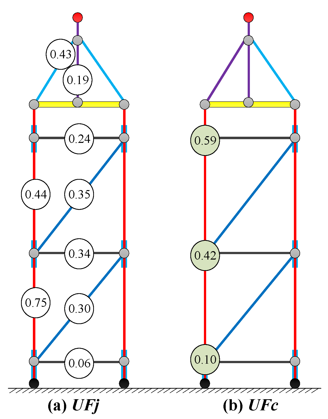
In this study, the total displacement ( δ X Y ) at the tower-substructure Interface Point (IP) and the combined stress ( σ ) at the lower jacket legs are calculated using the equations below:
δ X Y ( i ) = δ X ( i ) 2 + δ Y ( i ) 2
σ ( i ) = | σ a ( i ) | + σ b x 2 ( i ) + σ b y 2 ( i )
where, δ X ( i ) and δ Y ( i ) are the responses in X- and Y-directions at the angle of i ;   σ a ,   σ b x , and σ b y represent the axial and two bending stresses at the lower jacket legs.
The critical responses are then determined from the maximum values considering all environmental loading directions, and they are calculated by Equations (7) and (8):
δ max = max [ δ X Y ( i ) ] , i = 1 , , n  
σ max = max [ σ ( i ) ] , i = 1 , , n
Finally, the critical loading angles (orientations) are the directions that develop the critical structural responses.

4.4. Design Check

In order to check the strength capacity of the jacket members and joints, the utilization factor ( U F ) is used. The U F is composed of the ratio between actual and allowable stresses.
U F = actual   stress allowable   stress
According to NORSOK N-004 [21], the tubular members subject to combined loads should be designed to satisfy the following requirements at all locations along their height. Thus, the U F j of each jacket member is defined as follows:
  • Under axial tension and bending
    U F j = ( N ( j ) S d N t , R d ) 1.75 + M ( j ) y , S d 2 + M ( j ) z , S d 2 M R d
  • Under axial compression and bending
    F j = max ( N ( j ) S d N c , R d + 1 M R d { [ C m y M ( j ) y , S d 1 N S d N E y ] 2 + [ C m z M ( j ) z , S d 1 N S d N E z ] 2 } 0.5 , N ( j ) S d N c l , R d + M ( j ) y , S d 2 + M ( j ) z , S d 2 M R d )
    in which, N ( j ) S d ,   M ( j ) y , S d and M ( j ) z , S d are the design axial force, bending moments about y and z axes of the jacket members, respectively; M R d ,   N t , R d and N c , R d are design bending moment, axial tension, and compressive resistance, respectively; C m y and   C m z are reduction factors about y and z axes, respectively, taken from Table 6-2 in Reference [21]; N c l , R d is the design axial local buckling resistance; N E y and   N E z are Euler buckling strengths about y and z axes, respectively. Formulations of the forces, bending moment resistances, and Euler buckling strengths (i.e., M R d ,   N t , R d , N c , R d , N c l , R d ,   N E y and   N E z ) can be found in Section 6.3 of the Reference [21].
Similarly, the tubular joint check is also conducted to assess the strength capacity at the jacket joints. Joint resistance subject to both axial force and bending moment in the brace should be designed to satisfy the following condition [21]:
U F c = N ( b ) S d N ( b ) R d + ( M ( b ) y , S d M ( b ) y , R d ) 2 + M ( b ) z , S d M ( b ) z , R d
where N ( b ) S d ,   M ( b ) y , S d , and M ( b ) z , S d are the design axial force, in-plane, and out-of-plane bending moments of the brace members, respectively; N ( b ) R d ,   M ( b ) y , R d , and M ( b ) z , R d are the design axial, in-plane, and out-of-plane bending resistances, respectively, and taken in Section 6.3 of the Reference [21].

4.5. Assumptions for the Numerical Analysis

For the numerical analysis of the 4-leg jacket substructure, the following assumptions are adopted; Environmental loads (such as wind, wave, and current loads) acting on the jacket substructure (Figure 3a) are applied all in the same horizontal direction. This implies that the misalignment among α w i n d ( i ) ,   α w a v e ( i ) , and α c u r r e n t ( i )   (Figure 3b) is 0, which makes the critical environmental loading conditions.

5. Results of the Analysis
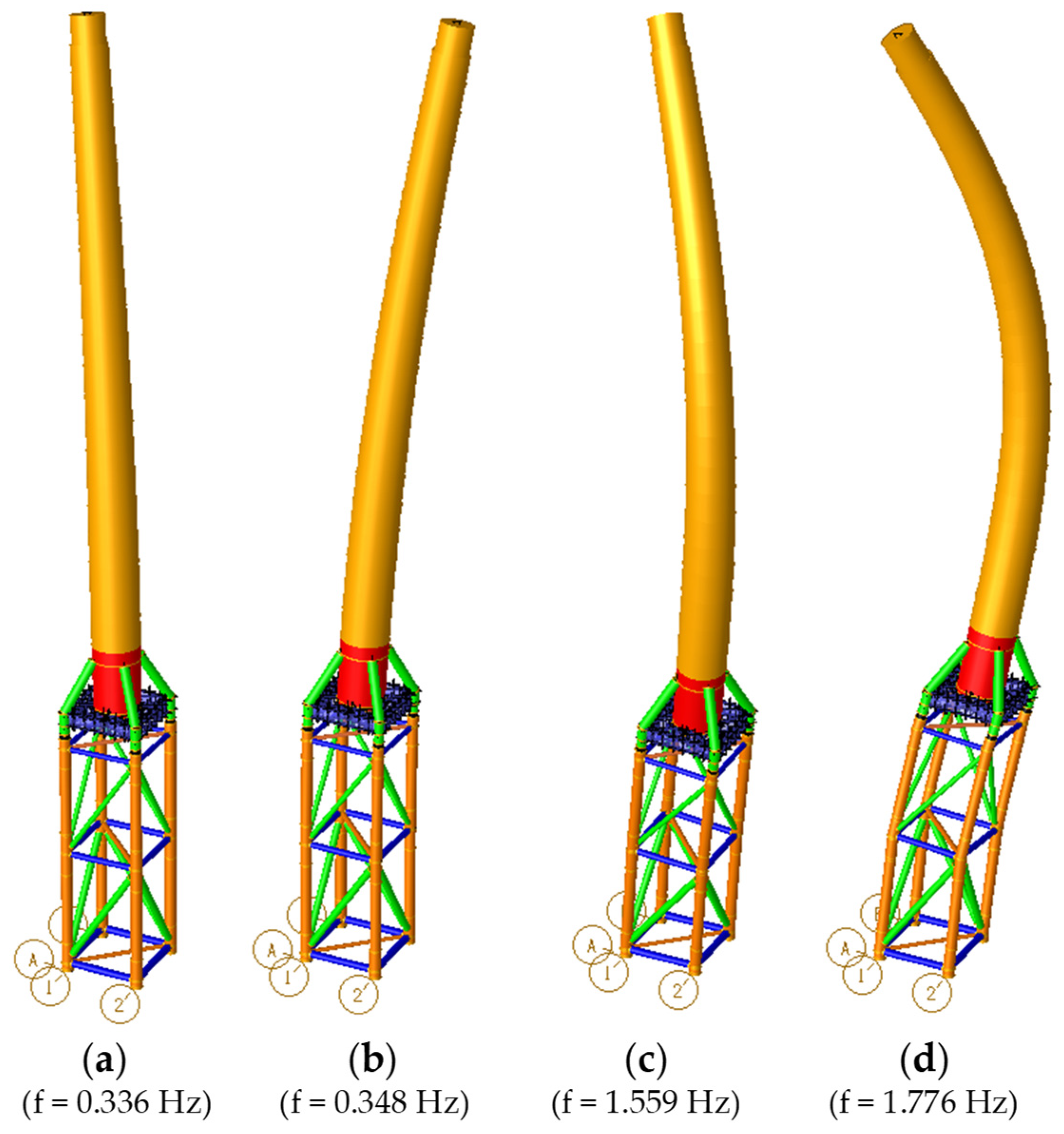
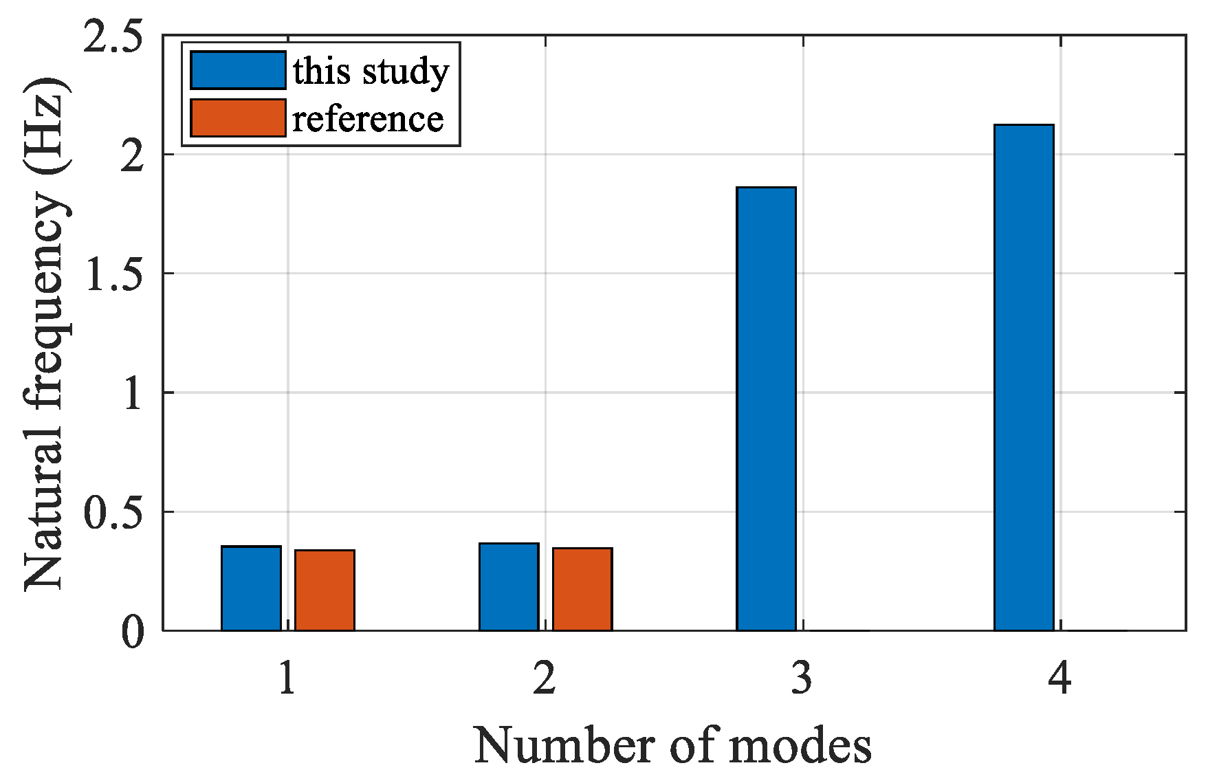
Using the analysis model of the 3MW Offshore Wind Turbine (OWT) support structure, modal analysis is first conducted to verify its appropriateness comparing to the design estimates in Reference [16]. Then, in order to find the critical bending direction of the selected 4-leg jacket substructure, extreme environmental loads are applied and its responding displacements and stresses are analyzed. The structural responses of the 4-leg jacket substructure are also investigated in this study under the critical Design Load Cases (DLCs), which are arranged in a matrix format. The DLC loads at the top of TP are calculated using the GH-Bladed software (Garrad Hassan and Partners Limited- Bristol, UK) [22], and the final matrix format is provided from the 3MW wind turbine manufacturer.
Finally, the extreme environmental loads and the DLC loads are combined together, and structural responses of the 4-leg jacket substructure are investigated under the combined loading conditions. The results are described in the following sub-sections.

5.1. Modal Analysis

Modal analysis is performed to ensure that the numerical model exhibits the same dynamic characteristics, compared to the reference 3MW OWT support structure given in POSCO [16]. To accurately capture the dynamic behavior, masses of the 3MW Rotor Nacelle Assembly (RNA) and flanges are also included in this analysis model (see Figure 2).
Visualized mode shapes of the full support structure (i.e., tower, Transition Piece (TP), and jacket structure) corresponding to their natural frequencies are shown in Figure 4. A comparison of the natural frequencies between the developed analysis model and the reference jacket substructure is made in Figure 5. As shown in the histogram, minor differences (that are less than 0.84% in both X- and Y- directions) are observed in the comparison of the first and the second natural frequencies. This indicates that the developed numerical model is acceptable for the structural analysis in order to understand overall structural behavior.
For higher mode shapes, eigenvalues of 1.559 Hz for the third mode and 1.776 Hz for the fourth mode, which lay beyond the upper boundary of the 3-blade passing frequency range (i.e., 0.35–0.6 Hz), are observed.

5.2. Structural Analysis

In order to find the critical bending direction of the selected 4-leg jacket substructure, extreme environmental loading conditions are considered in the analysis. The environmental loads (i.e., wind, wave, and current loads) are selected from the extreme ocean conditions in the West Sea in South Korea, which is chosen for the reference site in this study. The maximum lateral displacements at the top of TP and the maximum stresses at the lower jacket legs are also investigated under the critical DLC loads, which are arranged in a matrix format.
The schematic diagram of the loads acting on the 4-leg jacket substructure is graphically shown in Figure 6.

5.2.1. Structural Responses under Extreme Environmental Loads (Env Loads)

Under the extreme environmental loading conditions, a numerical analysis is conducted to find the critical bending direction of the selected 4-leg jacket substructure. A total of 24 loading angles, varying from 0° to 360° at intervals of 15°, are considered in this study. Figure 7 shows polar diagrams of the maximum lateral displacements at the tower-substructure Interface Point (IP) and the maximum stresses at the lower jacket legs.
The maximum lateral displacements of the jacket substructure subject to the simultaneous wind/wave/current loads are computed using Equation (7). As expected, the maximum lateral displacements at IP are very sensitive to the loading directionality of the environmental loads. As shown in Figure 7, the jacket substructure exhibits the maximum lateral displacement of 1.13 cm at both the angles of 135° and 315°.
The maximum stresses for all leg members (i.e., leg 1, leg 2, leg 3, and leg 4) at the lower level of the jacket structure are also plotted in Figure 7b. The stress patterns of leg 1 and leg 4 show similar responses, and the stress patterns of leg 2 and leg 3 also show the similarity. The critical responses are approximately 50 MPa both for leg 3 at 135° and for leg 2 at 315°, and these values are much larger than those calculated from leg 1 and leg 4. The differences between leg 2 and leg 3 or between leg 1 and leg 4 are caused by asymmetry of the Pratt bracing system.
From the observation, it can be found that the selected 4-leg jacket substructure shows the smallest bending resistance when the loads apply to the angles of 135° or 315°, which means one of the diagonal direction of the jacket substructure. Thus, in order to maximize the structural efficiency of the substructure, it is recommended that the direction of the diagonal of the 4-leg jacket substructure should be carefully decided when being installed in the ocean.

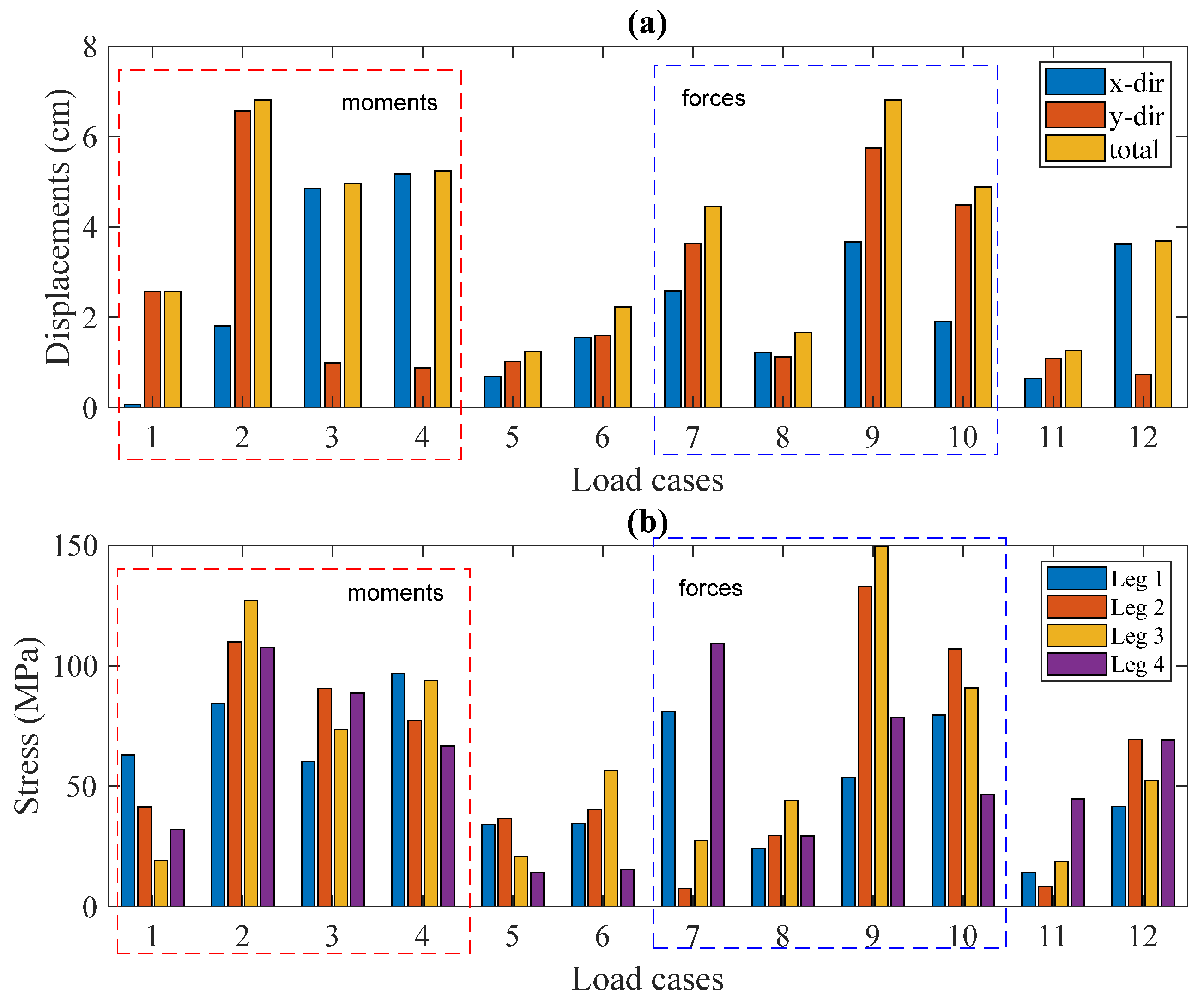
5.2.2. Structural Responses under DLC Loads

For the design of offshore jacket substructures, hundreds of DLC loads need to be considered to ensure the structures are safe during their lifetime. Information on the DLC loads can be found in IEC (2005) [23] or DVNGL-ST-0437 [24]. In this study, a total of twelve DLC loads corresponding to the absolute maximum design forces and design moments are arranged in a matrix format, as shown in Table 4. These critical DLC loads at the location of IP are provided by the 3MW wind turbine manufacturer.
Figure 8 illustrates the maximum lateral displacements at IP and maximum stresses at the lower jacket legs, under the given 12 DLC loads. In Figure 8a, the maximum lateral displacement of 6.82 cm is found for both the DLC2 and DLC9, corresponding to M x ,   m i n and F y , m a x   , respectively. This trend is very similar for the corresponding stresses at the lower jacket legs, as shown in Figure 8b. The maximum stresses for leg 3 are approximately 127 MPa under M x ,   m i n and 150 MPa under F y , m a x   . From Figure 8, it is found that illustrates DLC2, DLC3, DLC4, DLC9, DLC10 show relatively large structural responses.

5.3. Structural Responses under Combined Loads (Env Loads + DLC Loads)

A total of 288 cases (combination of 12 DLC loads with 24 Env loading directions) are analyzed in this sub-section. The main purposes of these analyses are (1) to identify the critical bending direction of the selected 4-leg jacket substructure under the 288 combined load cases (CBs), and (2) to investigate the portion of the Env load effects to the total response of the offshore wind substructure, in the case of jacket layout chosen in this study.
Figure 9 shows a comparison of the lateral displacements at IP, with an Env loading angle variation under the combined loads. The maximum responses of the only five CBs (i.e., CB2, CB3, CB4, CB9, and CB10) are plotted in this figure, because these load cases develop relatively large lateral displacements comparing to the other cases. As a note, CB2 means a combination of DLC2 with 24 Env loading directions. At the Env load angle of 120°, CB9 and CB2 produce the maximum lateral displacements of 8.79 cm and 8.68 cm, respectively. Meanwhile, the maximum values are 3.73 cm, 6.81 cm, and 2.99 cm for CB3, CB4, and CB10, respectively.
Similar to the lateral displacement responses, Figure 10 shows a comparison of the maximum stresses at the four jacket legs under the combined loads. The maximum stresses are found in leg 2 and leg 3, and the maximum values are 190 MPa and 230 MPa, respectively. Comparisons are also made for leg 1 and leg 4; however, these outcomes are less than those obtained from leg 2 and leg 3, with the maximum value of about 150 MPa for both cases. Another finding in this study is that the critical angle varies with a change of CBs. For instance, in Figure 10c the same pattern is found in CB2, CB4 and CB9, and the critical angle is found at 135°; whereas, this value is 335° for two rest cases (i.e., CB3 and CB10).
Furthermore, the outcomes also indicate that stress distributions of the jacket members and joint cans satisfy the ultimate criteria. The maximum stresses are below the material yield strength limit (355 MPa). For better evaluation, strength checks for the jacket substructure are performed, and their results are shown in Figure 11. In this figure, the maximum U F values of the jacket members and joint groups are shown. It indicates that the U F values are smaller than one, implying satisfaction of all jacket members and joints against their ultimate requirements.
In order to quantify how much the Env load effects contribute to the total responses of the jacket substructure, different comparisons are made in Figure 12 and Figure 13. The analysis results of CB9 are utilized, since they produce the largest structural responses comparing to the other combined load cases. In Figure 12 and Figure 13, the structural responses are normalized. This means the total (maximum) response of the jacket substructure under the condition of CB9 is defined as the scale of 100%.
In case of the lateral displacements at IP (see Figure 12), the maximum percentage of 27.24% is observed at 300°, while the average percentage is 15.7%. Similarly, for the stresses at the lower jacket legs, the maximum percentages are 25.81%, 37.39%, 33.17%, and 22.91% for leg 1, leg 2, leg 3, and leg 4, as plotted in Figure 13. The average percentage for all jacket leg members is around 20.0%. This result reveals that the effects of Env loads are not small comparing to the total structural responses of the 4-leg jacket substructure.

6. Conclusions and Observations

In order to investigate the directional bending performance of a 4-leg jacket substructure, an analytical study has been conducted. For the study, a numerical analysis model is developed. This analysis model is geometrically identical to the 3MW jacket substructure which is already installed in the Southwest offshore wind farm in South Korea.
Using the developed analysis model, structural performances of the 4-leg jacket substructure are studied under (1) extreme environmental loads (Env), (2) critical Design Load Cases (DLC), and (3) combined load cases (CB). Major findings from this study are summarized below:
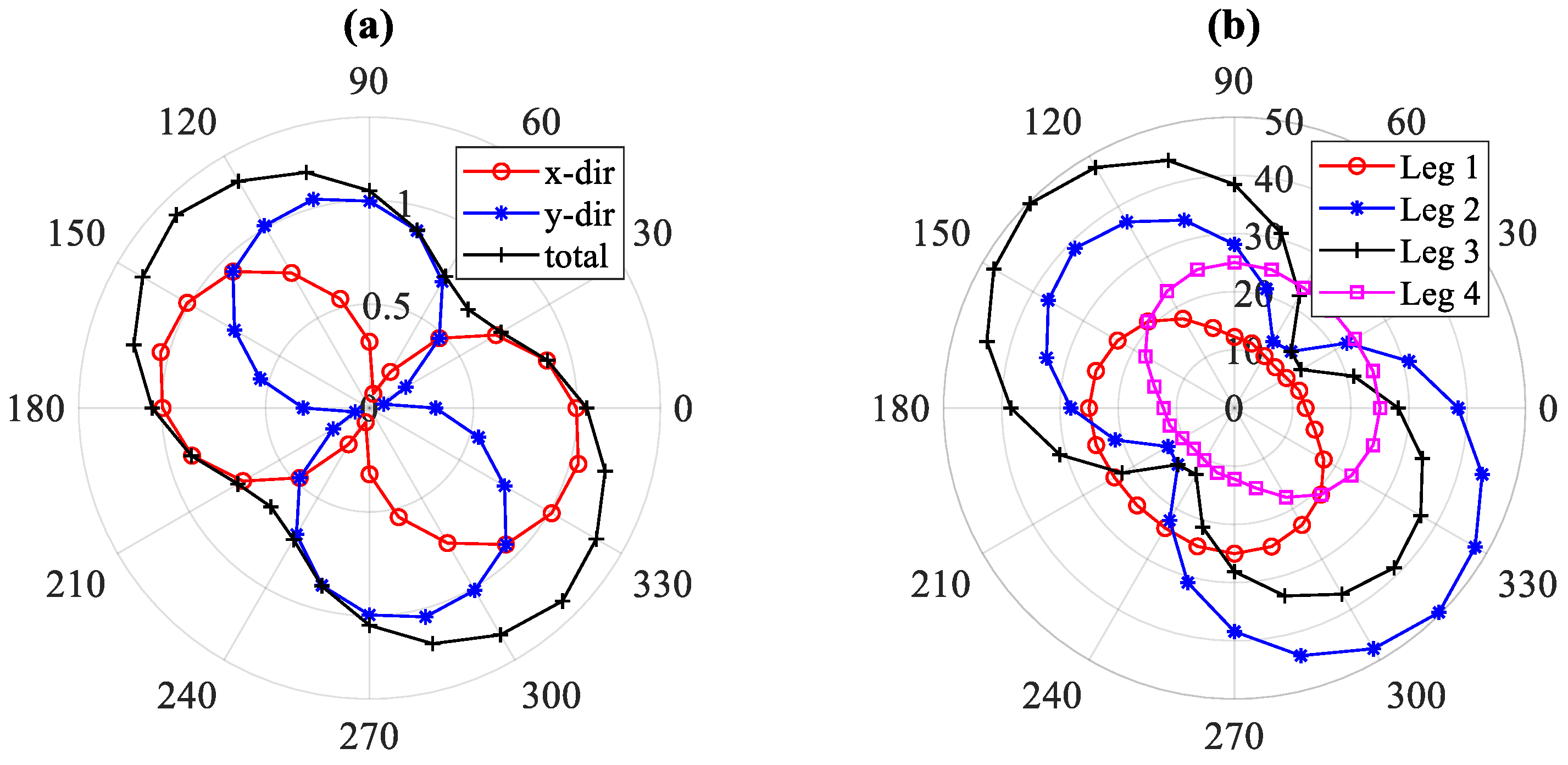
  • Under Env loading conditions, the 4-leg jacket substructure shows maximum structural responses (i.e., maximum lateral displacements at the tower-substructure interface and maximum stresses at the lower jacket legs) at the loading angles of 135° and 315°. This indicates that the smallest bending stiffness can be found in one of the 4-leg jacket diagonal directions.
  • From the study above, it is also found that the polar diagrams are very useful to present directional bending performances of the 4-leg jacket substructure.
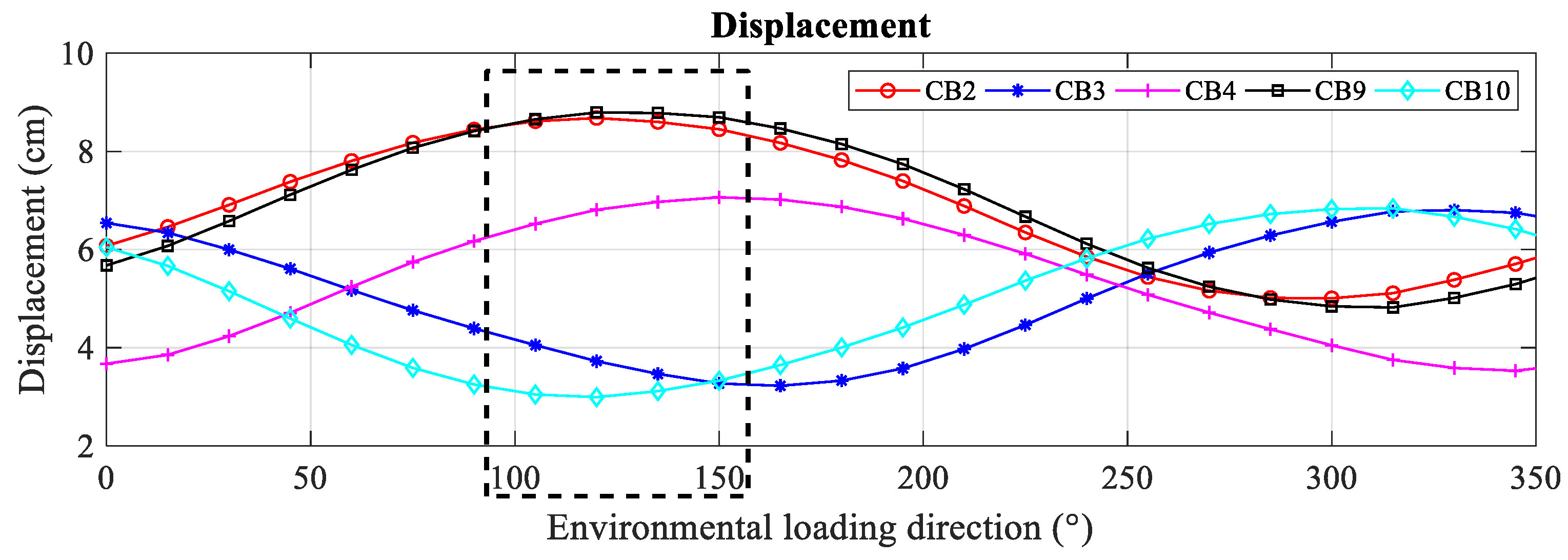
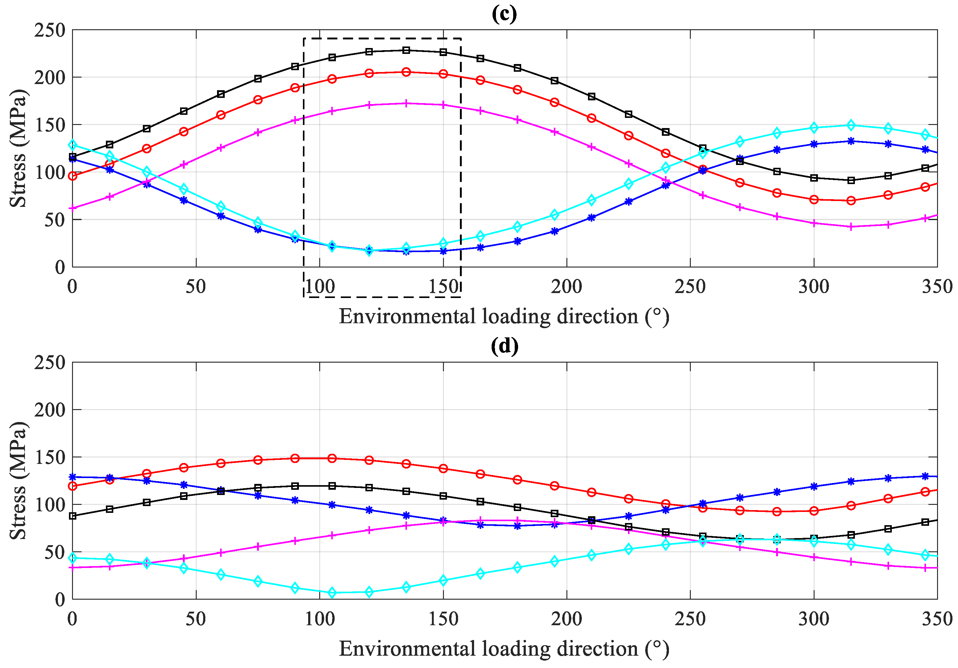
  • From the structural responses under 12 DLC loading conditions, relatively large lateral displacements and stresses are obtained in the cases of DLC2, DLC3, DLC4, DLC9, and DLC10. These five cases also showed similar results when the 12 DLC loads are combined with the 24 Env loading directions.
  • Under CB loading conditions, critical angles for the bending of the 4-leg jacket substructure are found to be from 105° to 150°. In order to maximize the structural efficiency of the jacket substructure, it is recommended that this range of the jacket’s angle in the plane should be avoided from the condition of facing the critical design loads.
  • Comparing to the total structural responses of the 4-leg jacket substructure, supporting a 3MW offshore wind turbine, it is found that the maximum Env load effects show a moderate contribution; the maximum percentage of 27.24% in the case of lateral displacements at the tower-substructure interface and the maximum percentage of 37.39% in the case of stresses at the lower jacket legs.

Author Contributions

Conceptualization, T.-T.T. and D.L.; methodology, T.-T.T. and S.K.; software, T.-T.T., S.K. and J.-H.L.; validation, D.L.; formal analysis, T.-T.T.; investigation, D.L.; data curation, T.-T.T., J.-H.L. and D.L.; writing—original draft preparation, T.-T.T.; writing—review and editing, T.-T.T., S.K. and D.L. All authors have read and agreed to the published version of the manuscript.

Funding

This work was supported by POSCO, a steel-making company headquartered in Pohang, the Republic of Korea, and the Korea Institute of Energy Technology Evaluation and Planning (KETEP) funded by the Ministry of Trade, Industry & Energy (MOTIE) of the Republic of Korea (No. 20183010025200 and No. 20183010025300).

Institutional Review Board Statement

Not applicable.

Informed Consent Statement

Not applicable.

Data Availability Statement

The data presented in this study are available on request from the corresponding author.

Conflicts of Interest

The authors declare no conflict of interest.

References

  1. Bhattacharya, S. Design of Foundations for Offshore Wind Turbines; Wiley: Hoboken, NJ, USA, 2019. [Google Scholar]
  2. Kim, D.H.; Lee, S.G. Reliability analysis of offshore wind turbine support structures under extreme ocean environmental loads. Renew. Energy 2015, 79, 161–166. [Google Scholar] [CrossRef]
  3. Shi, W.; Park, H.; Han, J.; Na, S.; Kim, C. A study on the effect of different modeling parameters on the dynamic response of a jacket-type offshore wind turbine in the Korean Southwest Sea. Renew. Energy 2013, 58, 50–59. [Google Scholar] [CrossRef]
  4. Shi, W.; Han, J.; Kim, C.; Lee, D.; Shin, H.; Park, H. Feasibility study of offshore wind turbine substructures for southwest offshore wind farm project in Korea. Renew. Energy 2015, 74, 406–413. [Google Scholar] [CrossRef]
  5. Kim, D.H.; Lee, S.G.; Lee, I.K. Seismic fragility analysis of 5MW offshore wind turbine. Renew. Energy 2014, 65, 250–256. [Google Scholar] [CrossRef]
  6. Chella, M.A.; Tørum, A.; Myrhaug, D. An overview of wave impact forces on offshore wind turbine substructures. Energy Procedia 2012, 20, 217–226. [Google Scholar] [CrossRef] [Green Version]
  7. Jeong, Y.-J.; Park, M.-S.; Kim, J.; Song, S.-H. Wave force characteristics of large-sized offshore ưind support structures to sea levels and wave conditions. Appl. Sci. 2019, 9, 1855. [Google Scholar] [CrossRef] [Green Version]
  8. Ko, K.; Kim, K.; Huh, J. Variations of wind speed in time on Jeju Island, Korea. Energy 2010, 35, 3381–3387. [Google Scholar] [CrossRef]
  9. Tran, T.-T.; Hussan, M.; Kim, D.; Nguyen, P.-C. Distributed plasticity approach for the nonlinear structural assessment of offshore wind turbine. Int. J. Nav. Archit. Ocean Eng. 2020, 12, 743–754. [Google Scholar] [CrossRef]
  10. Lyu, G.; Zhang, H.; Li, J. Effects of incident wind/wave directions on dynamic response of a SPAR-type floating offshore wind turbine system. Acta Mech. Sin. Xuebao 2019, 35, 954–963. [Google Scholar] [CrossRef] [Green Version]
  11. Kim, S.Y.; Kim, K.M.; Park, J.C.; Jeon, G.M.; Chun, H.H. Numerical simulation of wave and current interaction with a fixed offshore substructure. Int. J. Nav. Archit. Ocean Eng. 2016, 8, 188–197. [Google Scholar] [CrossRef] [Green Version]
  12. Lin, T.-Y.; Zhao, Y.-Q.; Huang, H.-H. Representative Environmental Condition for Fatigue Analysis of Offshore Jacket Substructure. Energies 2020, 13, 5494. [Google Scholar] [CrossRef]
  13. Zhang, J.; Kang, W.-H.; Sun, K.; Liu, F. Reliability-Based Serviceability Limit State Design of a Jacket Substructure for an Offshore Wind Turbine. Energies 2019, 12, 2751. [Google Scholar] [CrossRef] [Green Version]
  14. Chew, K.-H.; Eddie, Y.N.; Tai, K. Offshore Wind Turbine jacket substructure: A comparison study between four-legged and three-legged designs. J. Ocean Wind Energy 2014, 1, 74–81. [Google Scholar]
  15. Vorpahl, F.; Wojciech, P.; Daniel, K. Description of a basic model of the “UpWind reference jacket” for code comparison in the OC4 project under IEA Wind Annex 30. In Offshore Code Comparison Collaboration Continuation (OC4); National Renewable Energy Laboratory: Golden, CO, USA, 2013. [Google Scholar]
  16. POSCO. 4-Leg Jacket Substructure for 3MW Offshore Wind Turbine; Structural Design Report; POSCO: Pohang, Korea, 2017. [Google Scholar]
  17. Kim, J.Y.; Oh, K.Y.; Kang, K.S.; Lee, J.S. Site selection of offshore wind farms around the Korean Peninsula through economic evaluation. Renew. Energy 2013, 54, 189–195. [Google Scholar] [CrossRef]
  18. Structural Analysis Computer System (SACS), User’s Manual, Release 14, Version 0, Engineering Dynamics; Bentley: Chester County, PA, USA, 2019.
  19. DNVGL. DNVGL-DNV-OS-J101–Design of Offshore Wind Turbine Structures; DNVGL: Oslo, Norway, 2014. [Google Scholar]
  20. Tran, T.-T.; Kim, E.; Lee, J.; Lee, D. A study on dynamic response of 4-leg jacket structures under different Sea water levels. In Proceedings of the KWEA Fall Conference, Jeju, Korea, 13 November 2020. [Google Scholar]
  21. NORSOK. Norsok N-004 Standard-Design of Steel Structures; NORSOK: Oslo, Norway, 2004. [Google Scholar]
  22. Bossanyi, E. GH-Bladed Version 4.0 User Manual 2010; Garrad Hassan and Partners Limited: Bristol, UK, 2010. [Google Scholar]
  23. IEC. Wind Turbines-Part 1: Design Requirements; IEC: Geneva, Switzerland, 2005. [Google Scholar]
  24. DVNGL. DVNGL-ST-0437 Loads and Site Conditions for Wind Turbines; ISO: Geneva, Switzerland, 2016. [Google Scholar]
Figure 1. A 3MW offshore wind turbine selected for the study: (a) Site location; (b) A 3MW jacket substructure.
Energies 14 02725 g001
Figure 2. Modeling of the support structure: (a) Analysis model; (b) Cross-section (cm).
Energies 14 02725 g002
Figure 3. Environmental loads acting on the jacket substructure: (a) Loading representation; (b) Definition of environmental loading directionality.
Energies 14 02725 g003
Figure 4. Mode shapes of the support structure: (a) Mode 1; (b) Mode 2; (c) Mode 3; (d) Mode 4.
Energies 14 02725 g004
Figure 5. Comparison of natural frequencies of the support structure.
Energies 14 02725 g005
Figure 6. Loads acting on the 4-leg jacket substructure.
Energies 14 02725 g006
Figure 7. Polar diagrams under Env loads: (a) displacements at IP (cm); (b) stresses at lower jacket legs (MPa).
Energies 14 02725 g007
Figure 8. Structural responses under DLC loads: (a) displacements at IP (cm); (b) stresses at lower jacket legs (MPa).
Energies 14 02725 g008
Figure 9. Lateral displacements at IP under combined loads.
Energies 14 02725 g009
Figure 10. Stresses at lower jacket legs under combined loads: (a) Leg 1; (b) Leg 2; (c) Leg 3; (d) Leg 4.
Energies 14 02725 g010aEnergies 14 02725 g010b
Figure 11. Results of strength check: (a) Jacket members; (b) Joint cans.
Energies 14 02725 g011
Figure 12. Percentage contribution of Env loads (lateral displacement).
Energies 14 02725 g012
Figure 13. Percentage contribution of Env loads (stress): (a) Leg 1; (b) Leg 2; (c) Leg 3; (d) Leg 4.
Energies 14 02725 g013
Table 1. Geometrical and mechanical details of the 3MW offshore wind turbine.
DescriptionSymbolValueUnit
Rotor-Nacelle-Assembly (RNA)
Rating 3MW
Rotor orientation Upwind, 3 blades
Hub height above platform h H U B 56.78m
Mass of the rotor m R O T 64.60ton
Mass of the nacelle m N A C 128.00ton
Mass of the RNA m R N A 192.60ton
Tower
Bottom diameter d B O T 450.00cm
Bottom thickness t B O T 3.40cm
Top diameter d T O P 307.00cm
Top thickness t T O P 1.80cm
4-Leg Jacket Substructure
Height h S U B 32.47m
Leg diameter d L E G 104.70cm
Leg thickness t L E G 1.60cm
Brace diameter d B R A 50.80cm
Brace thickness t B R A 1.90cm
Table 2. Extreme environmental conditions at the reference site [16].
DescriptionSymbolValueUnit
Wind
Wind speed in 50-year condition V W 50 42.50m/s
Current
Current velocity in 50-year condition V C U R 1.04m/s
Wave
Average water depth d M S L 14.00m
Significant wave height in 50-year condition H S 50 5.97m
Wave period in 50-year condition T S 50 11.16s
Table 3. Material properties used for 4-leg jacket substructure.
ParameterSymbolValueUnit
Density γ 7850 kg / m 3
Young’s modulus E 210,000MPa
Yield strength f ys 355MPa
Poisson’s ratio ν 0.3-
Table 4. Critical DLC loads at the location of IP.
DLCDescriptionsForce (kN)Moment (kNm)
F x F y F z M x M y M z
DLC1 M x Max−39.0−959.0−5208.049,041.0−2496.02173.0
DLC2Min−114.0923.0−5197.0−47,885.0−4998.0−1731.0
DLC3 M y Max781.04.0−6424.02369.045,635.0373.0
DLC4Min−699.049.0−5168.01038.0−39,301.0−298.0
DLC5 M z Max31.0−146.0−5244.06720.05034.05385.0
DLC6Min−181.0198.0−5063.0−10,207.0−9979.0−6124.0
DLC7 F x Max1051.0807.0−4705.0−23,378.08965.0−1222.0
DLC8Min−978.0−653.0−4737.0−22,496.010,333.0−742.0
DLC9 F y Max−714.01384.0−4722.0−19,975.0−10,358.0−1072.0
DLC10Min392.0−1352.0−4739.011,407.01986.0964.0
DLC11 F z Max220.0745.0−4600.04275.03995.0885.0
DLC12Min639.023.0−7203.62282.037,895.0866.0
Publisher’s Note: MDPI stays neutral with regard to jurisdictional claims in published maps and institutional affiliations.

