Article

Self-Tuning Observer for Sensor Fault-Tolerant Control of Induction Motor Drive

Department of Electronics, Faculty of Electrical Engineering and Computer Science, VSB-Technical University of Ostrava, 70800 Ostrava, Czech Republic
*
Author to whom correspondence should be addressed.
Energies 2021, 14(9), 2564; https://doi.org/10.3390/en14092564
Submission received: 18 March 2021 / Revised: 19 April 2021 / Accepted: 23 April 2021 / Published: 29 April 2021

Abstract

:
This paper introduces a new solution for the speed and current sensor fault-tolerant direct field-oriented control of induction motor drives. Two self-adjusting observers derived from a modified current-based model reference adaptive system (CB-MRAS) are presented. Finally, the recursive least squares method was used to estimate the parameters of the used observers. The method, in the proposed solution, provides a very fast and accurate finding of the observer parameters while maintaining relative simplicity and ease of implementation. The presented algorithm eliminates the CB-MRAS observer dependence on the induction motor parameters and also compensates for the inaccuracies in the evaluation of the stator voltage vector. The proposed fault-tolerant control offers the drive operation while either a speed sensor or one/two current sensors fault occurs. The drive still works with the direct field-oriented control even when no current sensors are healthy. The proposed scheme was simulated in the MATLAB/Simulink software environment. Then the algorithm was implemented in a floating-point digital signal controller (DSC) TMS320F28335 and tested on an induction motor drive prototype of rated power of 2.2 kW to validate the proposed schemes.

1. Introduction

Induction motors are still among the most widely used machines for electromechanical energy conversion. Field oriented control of induction motors (IM) enables applications of this motor in high performance variable-speed drives and has become an industry standard. However, the mentioned control technique requires healthy drive components including current, voltage and speed sensors for correct operation. This is the reason why fault detection and fault-tolerant control belongs to the up-to-date research trends in the field of electrical drives, especially for safety applications, such as traction drives, automotive, electric aircrafts, etc. [1,2,3]. The source of the fault can be an electric motor [4,5,6,7], a power electronics converter [8,9], a microcomputer control system or sensors. Main sources of failures are power electronics converters and sensors [2].
The sensor fault-tolerant control includes two approaches:
  • When a sensor fault is detected, the system switches to an alternate form of the controller (typically from a closed loop control system to an open loop control system);
  • When a sensor failure is detected, the system still works in the closed control loop using estimated quantities (instead of the measured ones) provided by estimators.
Sensor fault detection methods can be divided into model or signal-based techniques [10]. The most common approach in current sensor fault detection is based on Kirchhoff’s first law [11]. If a sensor fails, two other remaining current sensors are used for compensation, but if two of three phase current sensors fail, Kirchhoff’s law is not applicable. In addition, the basic problem of this simple approach is that only two current sensors are often used for field-oriented control of induction motor drives. In the literature, model-based approaches are used for sensor fault detection, isolation and compensation, e.g., in [11,12]. The techniques are based on comparison between the measured quantities and the estimated ones. In [13], an adaptive observer based on a motor model is presented for phase current estimation, which is robust to changes in the stator and rotor resistance. The extended Kalman filter is also one of the popular techniques for estimating the rotor speed or stator currents of induction motor drives [14,15], but it is generally not easy for practical implementation. A parity-space-scheme-based sensor fault detection algorithm is proposed in [16]. As mentioned in the paper, the algorithm is not sensitive to parameter variations because no model knowledge is required, but compensation of sensor faults is not possible because no estimator is used. In [17], a method based on an adaptive observer with rotor resistance estimation is presented for the detection of current, speed and voltage sensor faults. In [3] and [18], a modification of an X-based model reference adaptive system (MRAS) based on the inner product of d- and q-axes currents and voltages is used to estimate the rotor speed of an induction motor (IM). In [3], an interesting concept of vector rotations to detect, isolate and compensate a faulty current sensor is introduced, but the reference stator current vector components in the [d, q] rotating reference frame are used instead of estimated quantities. In [19,20], a proposed scheme integrates three independent observers for the online monitoring of the state of induction motor current sensors. The observers can detect the faults and switch a drive to the tolerant field-oriented control mode even with only one healthy phase current sensor available (as mentioned in [19]). The schemes for the detection, isolation and compensation of speed and current sensor faults in [2] do not use a motor model or motor parameters. A detailed and interesting analysis of speed and current controllers’ responses during sensor faults are presented as well. In [15,21,22], decision algorithms are used to change the control strategies with respect to the current and speed measurement faults, but all these approaches do not work with field orientation when a fault occurs, so this is the reason why they provide low dynamic performance of the drive. In [23], the direct torque control, indirect field-oriented control and volts-per-hertz control are used in the case of a sensor fault or recovery. In the paper, speed, current and voltage sensors are considered. In [1], a current sensor fault-tolerant control method is presented for the direct torque control of induction motor drives. In this case, a third-difference of the stator currents and a current estimator are used for the detection of the current sensor fault. In the literature, artificial-intelligence-based techniques are also used in the field of fault identification [24]. In [25], a presented approach based on polynomial chaos theory is used for validation and monitoring of sensors behavior. In this case, the fuzzy inference is implemented to combine all available sensors information, but the implementation of such algorithms is not easy.
In this paper, a new solution for the speed and current fault-tolerant control of induction motor drives equipped with a rotor speed encoder and two-phase current sensors is presented. The main contributions of the proposed approach are the following:
  • The method is based on the comparison between the measured and estimated speed and stator currents, respectively. For the speed and current estimation, two observers derived from the current-based MRAS (CB-MRAS [26]) observer are proposed for both the detection of a faulty sensor and also compensation using the estimated rotor speed or stator currents;
  • The algorithm is much simpler in comparison with state observers (Luenberger observer etc.) or the Kalman filter, but it provides an accurate estimation of the rotor speed or stator current vector (see chapter 3 and 4 for the simulation and experimental results);
  • The disadvantage of most MRAS-type observers is the influence of the motor parameters (mainly the stator and rotor resistance) on the quality of the estimated quantities, especially at low speeds [26,27,28,29,30,31,32,33]. The proposed approach is independent of the motor parameters using a recursive least square method (RLS) to estimate the parameters of the speed and current observers. Moreover, the RLS method is easy for implementation in digital signal controllers, and it enables us to compensate for the inaccuracies in the evaluation of the stator voltage vector so that the reference stator voltage vector (the input to the PWM, see Figure 1) can be directly used as the input to the observers and a nonlinear voltage-source inverter model (dead times compensation, voltage drops etc.) is not needed in the control scheme;
  • The proposed fault-tolerant control offers the drive operation while a speed sensor or one/two current sensors fault occurs;
  • The approach enables the drive operation in the direct field-oriented control (DFOC) even when all current sensors are faulty. In the literature concerning the fault-tolerant control, the indirect field-oriented control (IFOC) is very often used;
  • The presented solution based on the RLS can be used for other new MRAS-type concepts as the CB-MRAS with an auxiliary variable [31] to avoid the motor parameters influence.
This paper is organized as follows. Section 2 deals with the proposed speed and current sensor fault-tolerant control. The simulation and experimental results are shown in Section 3 and Section 4, respectively. Finally, conclusions are presented in Section 5.

2. Fault-Tolerant Control of Induction Motor Drive

The proposed fault-tolerant control of induction motor drive considering the operation under either the speed or current sensor fault is shown in Figure 1. The system uses two current sensors and one rotor speed sensor. The current sensors can be placed in any two stator phases of a three-phase induction motor. The control is based on the conventional DFOC in Cartesian coordinates. For the DFOC induction motor drives, knowledge of the rotor magnetic flux vector is required.
When all sensors are healthy this vector is determined using the current model of the rotor flux defined in Equation (1) [34]:
ψ ^ R α β = [ ( j ω R 1 T R ) ψ ^ R α β + 1 T R L m i S α β ] d t
where ψ ^ R α β is the rotor flux vector and i S α β is the stator current vector (measured) in the stationary reference frame [α, β], ω R is the electrical rotor speed (measured), Lm is the magnetizing inductance and TR = LR/RR is the rotor time constant, LR and RR are the rotor inductance and resistance.
Two self-tuning observers, described in the following subsections, are the most important part of the control structure in Figure 1. The observers secure necessary speed or current feedback for the appropriate controllers under speed or current sensor failure, respectively.

2.1. Control under Speed Sensor Failure

To ensure the correct operation of the DFOC, it is necessary to detect the error signal from the rotor speed sensor and replace it with the output signal from the rotor speed observer—this means switching to a so-called speed sensorless control mode. Various application-dependent strategies can be used to detect the speed sensor failure. In this paper, the measured speed ω R is compared to the speed estimated by the CB-MRAS observer ω ^ R and the speed sensor failure is detected by Equation (2):
If   | ω R ω ^ R | ε S   then   ω Rcorr = ω ^ R ;   ψ ^ R = ψ ^ R 1 α β else   ω Rcorr = ω R ;   ψ ^ R = ψ ^ R α β ,
where ω Rcorr is the corrected speed (the output of the fault-tolerant algorithm—see Figure 1), ψ ^ R is the rotor magnetic flux vector used in the DFOC (see Figure 1). The ε S is a threshold value, which setting mainly depends on maximum noise and accuracy in the speed measurement and the estimated speed quality. In the literature, a standard used method for the threshold value evaluation is not available, and this is the reason why the threshold is mostly set according to the experience [3]. After the experimental testing, we found an adaptive speed threshold defined by:
If   | ω Rref | < 150   rpm   then   ε S = 0.1 | ω Rref | else   ε S = 0.05 | ω Rref | ,
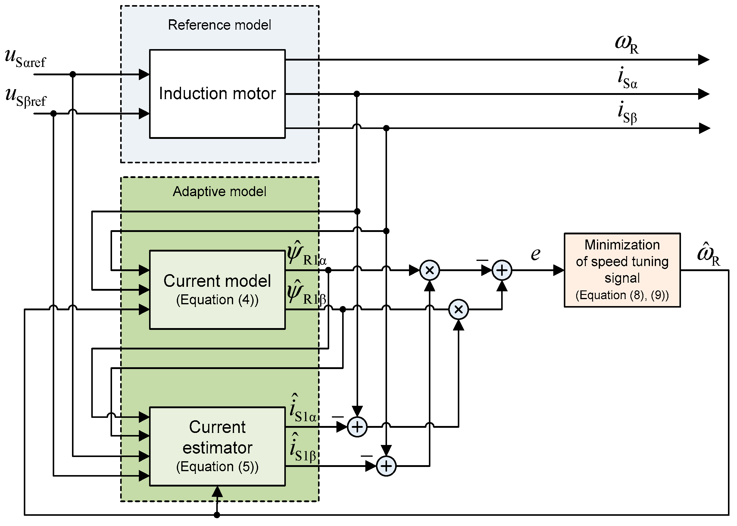
where ω Rref is the demanded rotor speed. The rotor speed ω ^ R is estimated by the CB-MRAS observer based on [26]. As shown in Figure 2, the CB-MRAS uses two adaptive models—a current model of the rotor flux and a current estimator.
If the speed sensor fault occurs, the rotor flux vector is evaluated using the adaptive current model of the rotor flux described in Equation (4):
ψ ^ R 1 α β = [ ( j ω ^ R 1 T R ) ψ ^ R 1 α β + 1 T R L m i S α β ] d t .
The stator current estimator is defined by Equation (5):
i ^ S 1 α β + T i ( CB ) d   i ^ S 1 α β d t = K 1 ( CB ) u S α β ref + K 2 ( CB ) ψ ^ R 1 α β j ω ^ R K 3 ( CB ) ψ ^ R 1 α β ,
where u S α β ref is the reference stator voltage vector in the stationary reference frame [α, β]; K1(CB), K2(CB), K3(CB), Ti(CB) are the CB-MRAS parameters given by the following forms:
K 1 ( CB ) = L R L m ( L R R S L m + L m T R ) ;   K 2 ( CB ) = L m T R L R R S + L m 2
K 3 ( CB ) = 1 ( L R R S L m + L m T R ) ; T i ( CB ) = L S L R L m 2 L m ( L R R S L m + L m T R )
where LS and RS are the stator inductance and resistance. It follows from Equations (6) and (7) that the estimated stator current vector i ^ S 1 α β is affected by the IM parameters.
The adaptation algorithm is based on the comparison of the measured and estimated stator current vector using the Lyapunov’s stability criterion [26]:
e = e i S α ψ ^ R 1 β e i S β ψ ^ R 1 α = ( i S α i ^ S 1 α ) ψ ^ R 1 β ( i S β i ^ S 1 β ) ψ ^ R 1 α ,
ω ^ R = K P e + K I e d t .
The speed tuning signal e is processed by a PI controller. The controller output is the estimated rotor speed ω ^ R . The CB-MRAS enables one to avoid the well-known problems concerning the pure integration in the case of the RF-MRAS [34].

2.2. Control under Current Sensor Failure

The proper stator current feedback is critical for reliable control operation. The stator current failure is detected by Equations (10)–(12):
If   | i S α i ^ S α | < ε C   and   | i S β i ^ S β | < ε C   then i S α β corr = i S α β ; ψ ^ R = ψ ^ R α β ,
If   | i S α i ^ S α | < ε C   and | i S β i ^ S β | ε C   then i S α corr = i S α ;   i S β corr = i ^ S β ;   ψ ^ R = ψ ^ R 2 α β ,
If   | i S α i ^ S α | ε C   then   ( i S β   is   also   not   correct   because   of   Clarke   transformation ) i S α β corr = i ^ S α β ;   ψ ^ R = ψ ^ R 2 α β ,
where i ^ S α β = i ^ S α + j i ^ S β is the estimated stator current vector and i S α β corr is the corrected stator current vector (the output of the fault-tolerant algorithm—see Figure 1). The ε C is a threshold value, which setting depends on many factors, e.g., maximum noise and accuracy in the current measurement, dc offset of a sensor, machine load, the estimated current quality, etc. In the literature, a standard used method for the threshold value evaluation is not available, and this is the reason why the threshold is mostly set according to the experience [3]. To take into account a machine load and after the experimental testing, it was chosen an adaptive current threshold equal to 15% of the magnitude of the stator current vector evaluated from the reference values of d- and q-axes currents:
ε C = 0.15 i Sdref 2 + i Sqref 2 .
The flux producing stator current in Equation (13) is very important for the correct current sensor fault detection when the drive is not subjected to load ( i Sq is close to zero).
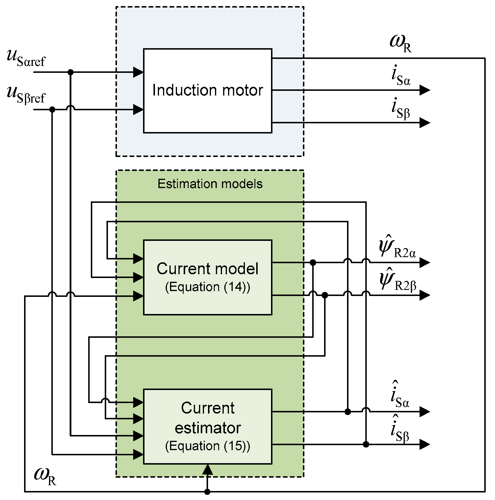
The stator current vector estimation is based on a modified CB-MRAS observer (see Figure 3). The fundamental adaptive models defined in Equations (4) and (5) are reformulated to the form:
ψ ^ R 2 α β = [ ( j ω R 1 T R ) ψ ^ R 2 α β + 1 T R L m i ^ S α β ] d t ,
i ^ S α β + T i ( CB ) d i ^ S α β d t = K 1 ( CB ) u S α β ref + K 2 ( CB ) ψ ^ R 2 α β j ω R K 3 ( CB ) ψ ^ R 2 α β .
The current model defined by Equation (14) provides the estimation of the rotor flux vector components in the stationary reference frame [α, β]. The current estimator defined by Equation (15) calculates the components of the stator current vector, also in the [α, β] frame. It is evident from Figure 3 that the DFOC can operate without any stator current measurement, only the rotor speed information from the sensor is required (see Figure 1).

2.3. Self-Tuning of Rotor Speed and Stator Current Observers

Fundamental Equations (5) and (15) of the applied rotor speed and stator current observers depend on the following parameters K1(CB), K2(CB), K3(CB) and Ti(CB), which are influenced by the induction motor parameters and their changes. Bad settings and variations of these parameters strongly deteriorate the accuracy of the estimation of the stator current and the rotor speed. Another factor that influences the accuracy of the estimation is the correct evaluation of the components of the stator voltage vector. The precise reconstruction of the stator voltage vector is difficult; therefore, the proposed self-tuning algorithm not only adapts the parameters K1(CB), K2(CB), K3(CB) and Ti(CB) but also compensates uncertainty in the stator voltage reconstruction; therefore, the nonlinear voltage-source inverter model (dead times compensation, etc.) is not needed.
The proposed self-tuning algorithm uses the recursive least square method (RLS). The RLS is applied to arbitrary component (α or β) of the stator current estimator defined by Equations (5) and (15) respectively, where the measured both stator current components and rotor speed are used:
i S α = K 1 ( CB ) u S α ref + K 2 ( CB ) ψ ^ R α + ω R K 3 ( CB ) ψ ^ R β T i ( CB ) d i S α d t .
For the implementation of the RLS, the following substitution is used:
y = p 1 u 1 + p 2 u 2 + p 3 u 3 + p 4 u 4 .
The actual output of the system y is, in this case, the α component of the stator current vector i S α . The components of the input vector u and vector of the search parameters p are defined as:
u 1 = u S α ref   ,   u 2 = ψ ^ R α   ,   u 3 = ω R ψ ^ R β   ,   u 4 = d i S α d t ,
p 1 = K 1 ( CB )   ,   p 2 = K 2 ( CB )   ,   p 3 = K 3 ( CB )   ,   p 4 = T i ( CB ) .
The new estimate of the parameters vector p(k + 1) is given by the following Equations (20)–(23) [35]:
e ( k + 1 ) = y ( k + 1 ) u T ( k + 1 ) p ( k ) ,
q ( k + 1 ) = P ( k ) u ( k + 1 ) λ + u T ( k + 1 ) P ( k ) u ( k + 1 ) ,
P ( k + 1 ) = 1 λ [ P ( k ) q ( k + 1 ) u T ( k + 1 ) P ( k ) ] ,
p ( k + 1 ) = p ( k ) + q ( k + 1 ) e ( k + 1 ) ,
where λ is the forgetting factor (the best results were achieved with λ = 0.999), the initial settings of the parameters vector is p(0) = [0, 0, 0, 0]T and the following covariance matrix:
P ( 0 ) = [ 0.1 0 0 0 0 0.1 0 0 0 0 0.1 0 0 0 0 0.1 ] .
The RLS algorithm is simple for implementation and not computationally intensive (its calculation takes 3.4 µs on target TMS320F28335 using the C programming language). The most difficult implementation problem has been the derivative of the stator current occurring in Equation (16). Finally, the integration of Equation (16) and its use for the RLS algorithm proved to be the best solution of the problem:
i S α d t = K 1 ( CB ) u S α ref d t + K 2 ( CB ) ψ ^ R α d t + K 3 ( CB ) ω R ψ ^ R β d t T i ( CB ) i S α
u 1 = u S α ref d t   ,   u 2 = ψ ^ R α d t   ,   u 3 = ω R ψ ^ R β d t   ,   u 4 = i S α .
When the drive operates in normal mode, the optimal observers parameters are set for the accurate sensor fault detection and then compensation using the RLS method. If the speed or current sensor fault occurs the RLS algorithm is deactivated and the drive uses the speed or current observer. In general, the FOC performance with sensors is always better than any sensorless method, which often has operational difficulties in a low-speed range (10% of the rated speed and less) due to the sensitivity of machine parameters, the nonlinearity of inverters, etc. IMDs should not generally operate with the faulty sensor for a long time and the broken sensor should be repaired or replaced as soon as possible to recover the normal operation.

3. Simulation Results

The correct function of the proposed control has been verified by the simulation of the induction motor drive of the rated power of 2.2 kW in the Matlab-Simulink. The parameters of the motor are given in Table 1. A voltage-source inverter works with these parameters—the dc-link voltage is 300 V; the switching frequency is 20 kHz.
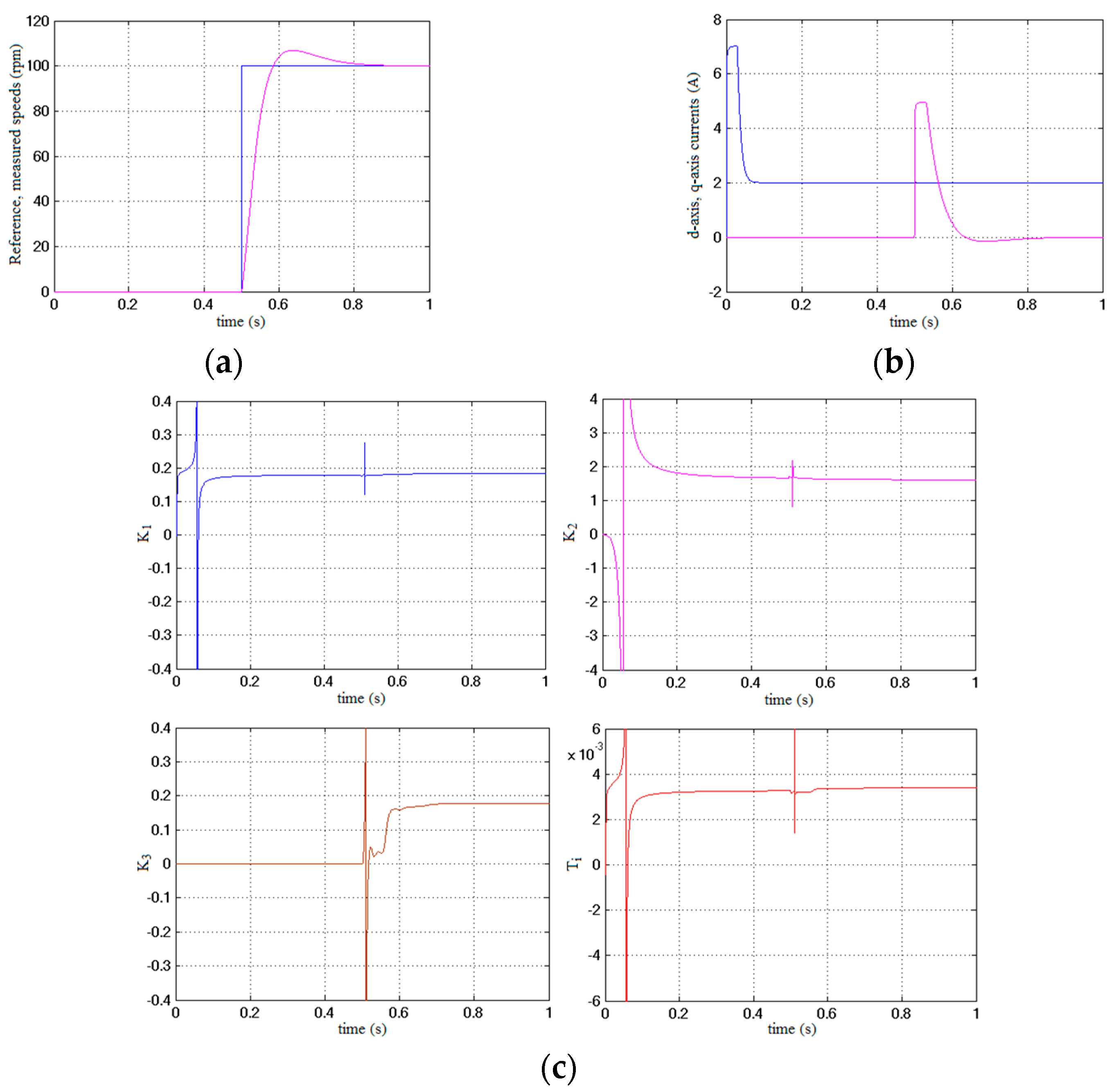
First, the drive was operating with all healthy sensors and the self-tuning algorithm was used to find the correct parameters of the observers. The K1(CB), K2(CB), K3(CB) and Ti(CB) parameters are found very fast and accurately in less than 0.8 s. The parameter identification test shown in Figure 4 consisted of the drive start-up, the motor excitation and acceleration from 0 to 100 rpm. The found parameters of the observers are presented in Table 2.
The simulation results for the speed sensor fault at 1 s are shown in Figure 5a. At the beginning of the test, all sensors are healthy. The motor is excited at 0 s and acceleration from 0 to 100 rpm is commanded at 0.25 s. The drive works with the defined reference speed of 100 rpm according to Figure 5a. By comparing the actual and estimated rotor speed, the fault-tolerant algorithm (FTA) detects the fault in the rotor speed sensing (see Equation (2) and Section 2.1), and the DFOC of the induction motor uses the estimated rotor speed instead of the measured rotor speed. The output from the FTA block (see Figure 1 and Figure 2) is the corrected rotor speed, which is equal to the measured speed in the case of healthy speed sensor and equal to the estimated speed when a speed sensor fault occurs. It can be seen from Figure 5a that the electric drive is able to normally operate even after the rotor speed sensor has failed.
The simulation results for the a-phase current sensor fault at 1 s are shown in Figure 5b. At the beginning of the test, all sensors are healthy. The motor is excited at 0 s, and acceleration from 0 to 100 rpm is commanded at 0.25 s. The drive works with the defined reference speed of 100 rpm according to Figure 5b. After a current sensor failure in the a-phase, both current vector components expressed in the stator reference frame are not correct because of the Clarke transformation. By comparing the actual and estimated stator currents, the FTA detects the failure in the stator current sensing (see Equations (10)–(12) and Section 2.2) and the DFOC algorithm uses the estimated stator current vector obtained from the stator current observer. The output of the FTA block is the corrected stator current vector i S α β corr and the rotor magnetic flux vector ψ ^ R used in the DFOC. It can be seen from Figure 5b that the electric drive is able to properly operate even after the stator currents measurement has failed.

4. Experimental Results

The proposed fault-tolerant control including the rotor speed observer, the stator current observer and the self-tuning algorithm is experimentally validated on a laboratory prototype of the induction motor drive with the DFOC. The prototype consists of the induction motor (its parameters are defined in Table 1) fed by an indirect frequency converter with a voltage-source inverter, a second induction motor (for loading) and a control system based on the Texas Instruments Digital Signal Controller TMS320F28335. A sampling frequency of 20 kHz is set for the real time processing of the algorithms. The rotor speed is measured by an incremental encoder with resolution of 2048 pulses per revolution. The dc-link voltage is 300 V for all experimental results.
First, the drive was operating with all healthy sensors (a speed sensor and two current sensors), and the self-tuning algorithm was used to find the correct parameters of the observers. The parameters are found quite fast, after 10 s (right after the motor excitation, acceleration from 0 to 100 rpm and speed reversal to −100 rpm), see Figure 6 and Table 2 for the experimental results of the found observers parameters. It is obvious from Table 2 that the identified parameters of the observers by simulation are almost identical to those of the values determined by the calculation from the nominal motor parameters.
The experimentally obtained parameters show slight differences, the largest difference occuring with the K2(CB). The reason for these differences is that the used nominal motor parameters may not exactly match the actual values, and the self-tuning algorithm also compensates for inaccuracies when evaluating the stator voltage vector (for more details, see Section 2.3).
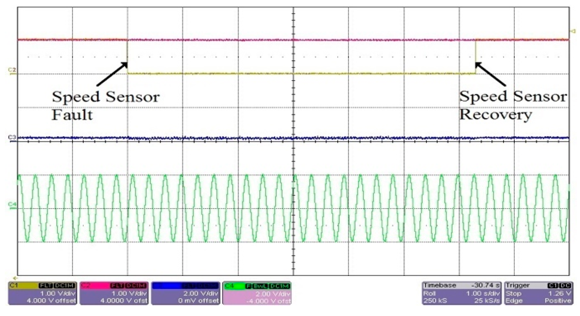
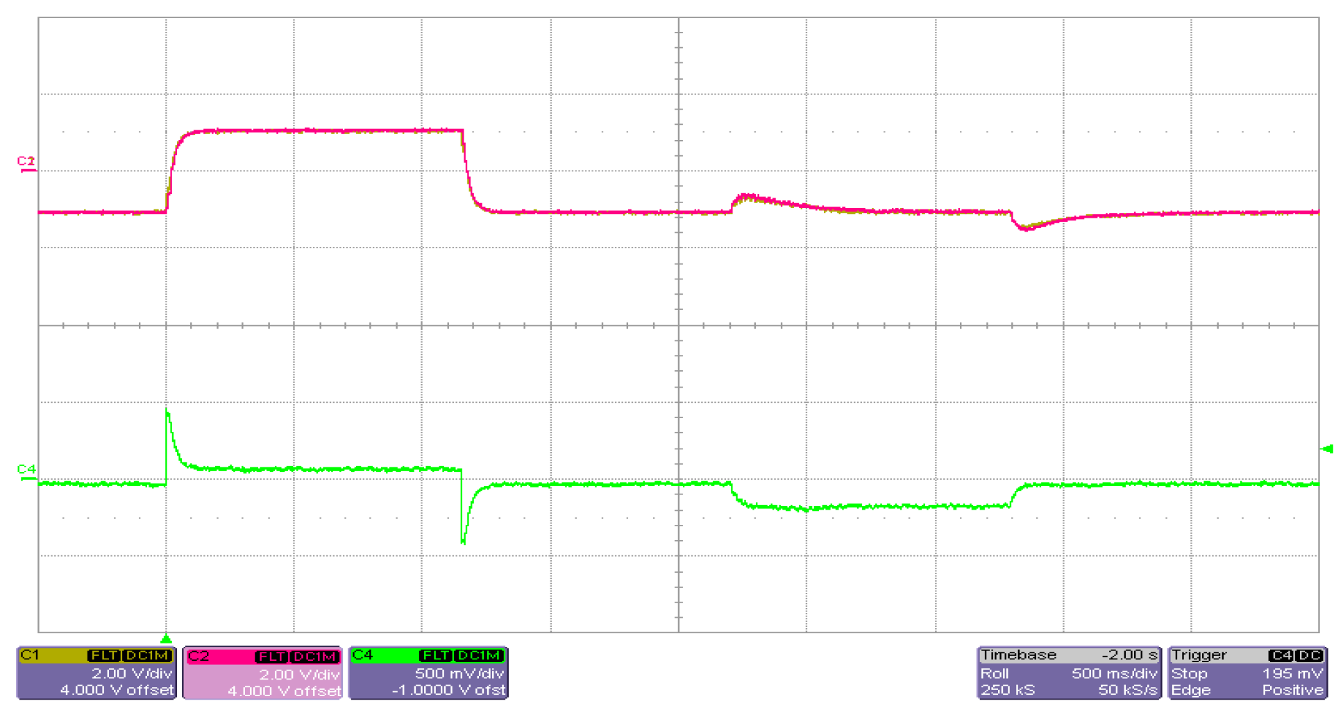
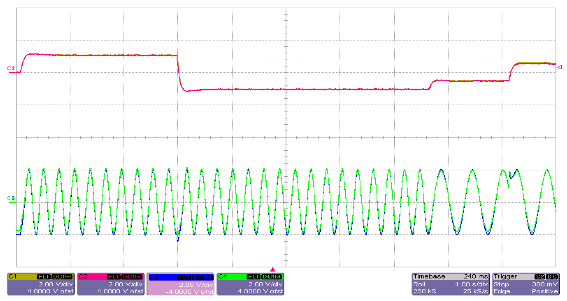
The experimental results for the speed sensor fault are shown in Figure 7, Figure 8 and Figure 9. At the beginning of the test, all the sensors are healthy. Figure 7 shows a situation where the rotor speed sensor of the motor is intentionally disabled and subsequently put into operation again. While the rotor speed sensor is malfunctioning, the FTA detects the fault in the rotor speed sensing (see Equation (2) and Section 2.1) and the control passes to the speed sensorless control mode of IM using the rotor speed observer (see Figure 8 and Figure 9). It is evident from the courses that the transitions between these control modes, during the operation of the drive, run smoothly without any visible disturbances and the drive normally operates even after the rotor speed sensor has failed. In Figure 8 and Figure 9, the measured rotor speed is shown for comparison purposes only, and it is not used in the control structure during the speed sensorless control mode. The measured and estimated rotor speeds are very similar; therefore, it is necessary to zoom Figure 8 and Figure 9 to see both speeds.
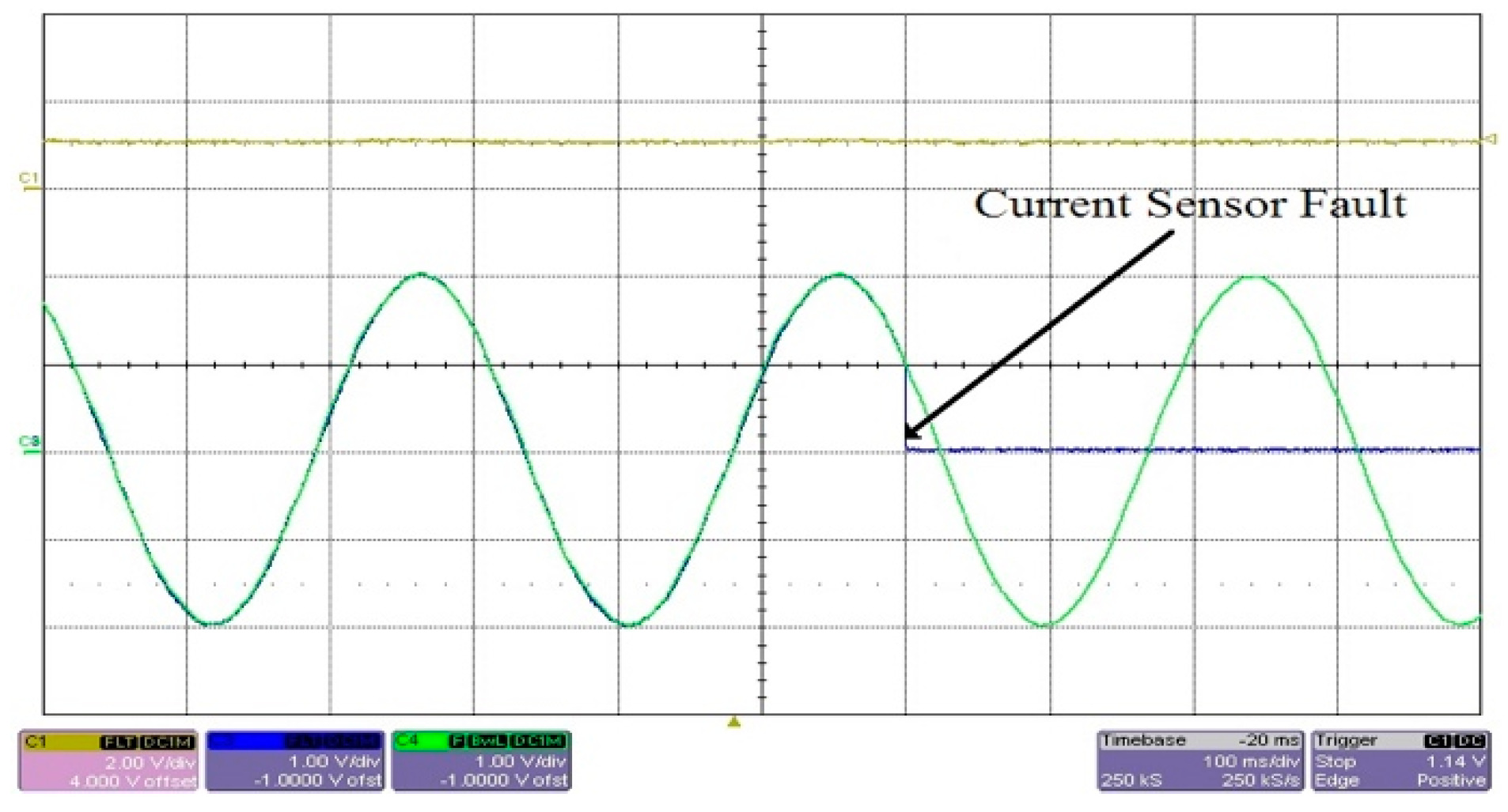
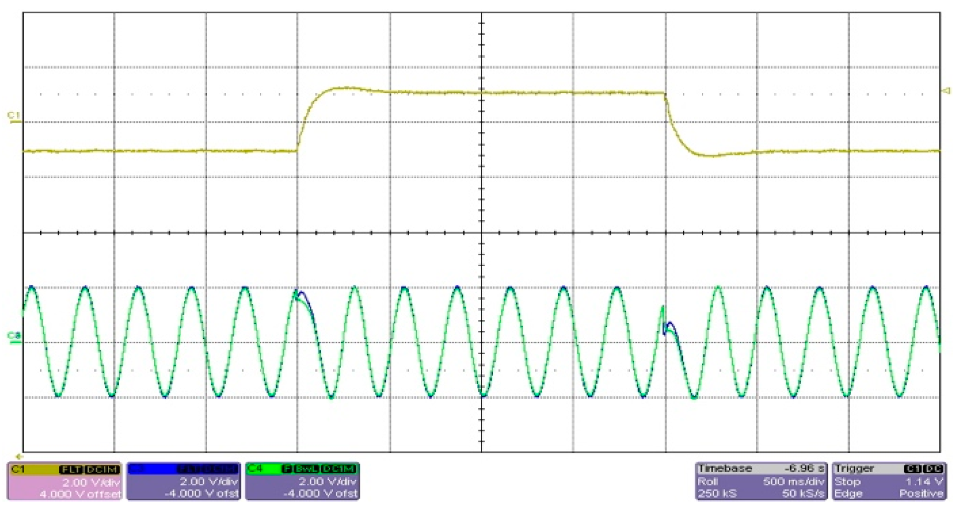
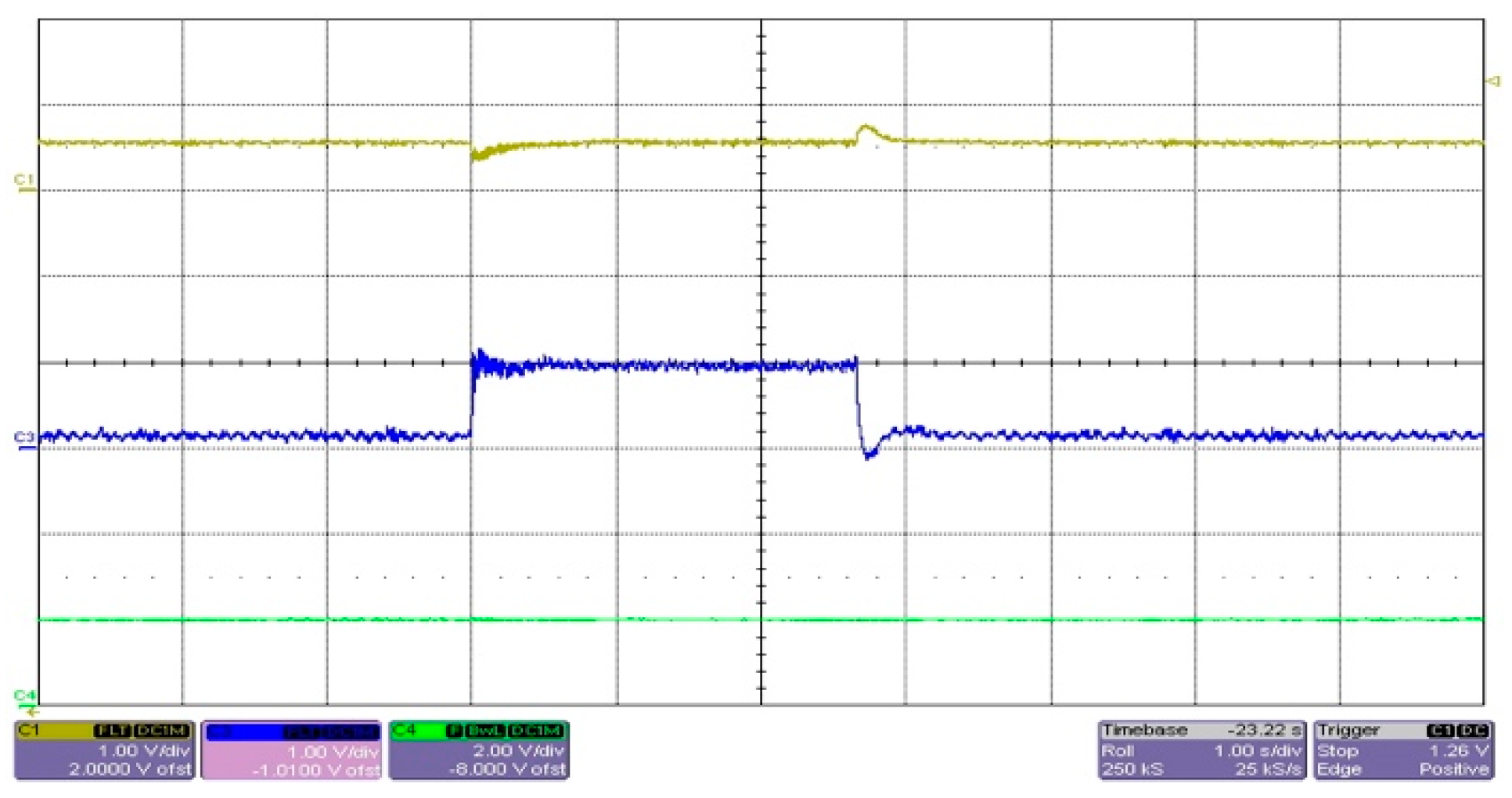
The experimental results for both stator current sensor faults (in a-phase and b-phase) are shown in Figure 10, Figure 11, Figure 12 and Figure 13. At the beginning of the test, all the sensors are healthy. Figure 10 shows a situation where both stator current sensors are intentionally disabled. While all the current sensors are malfunctioning, the FTA detects the fault in the stator current sensing (see Equations (10)–(12) and Section 2.2) and the control passes to the current sensorless control mode of IM using the stator current observer (see Figure 11, Figure 12 and Figure 13). It is evident from the experiments that the transitions between the sensor and sensorless control modes, during the operation of the drive, run smoothly without any visible disturbances, and the drive normally operates even after all the stator current sensors have failed. In Figure 11 and Figure 12, the measured stator currents are shown for comparison purposes only, and they are not used in the control structure during the current sensorless DFOC control.

5. Conclusions

This paper presents a new method of the speed and current sensor fault-tolerant control for induction motor drives. This approach enables the detection, isolation and compensation of either the speed or all current sensors faults using the estimated rotor speed and stator currents. For these purposes, self-tuning stator current and rotor speed observers have been proposed. The self-tuning algorithm is based on the recursive least squares method. The self-tuning strategy eliminates the dependence of the observers on the motor parameters and is also able to compensate for inaccuracies when evaluating the components of the stator voltage vector, which can significantly affect the precision of the estimation. The presented simulation and experimental results show very accurate rotor speed and stator current estimations in steady states and transient states as well, including a very low speed and load operation. From the results, it is obvious that this sensor fault-tolerant DFOC drive can operate well even when no healthy phase current sensor is available. The proposed method makes the induction motor drive more robust and reliable and it is suitable for safety crucial applications, e.g., in the field of traction vehicles and automotive drivetrains.

Author Contributions

Conceptualization, M.K. and P.P.; methodology, M.K. and P.P.; software, M.K. and J.S.; validation, M.K., J.S. and P.P.; formal analysis, M.K.; investigation, M.K., P.P. and J.S.; resources, P.S.; writing—original draft preparation, M.K.; writing—review and editing, P.P. and M.K.; visualization, M.K.; supervision, P.P.; project administration, P.S.; funding acquisition, P.S. and M.K. All authors have read and agreed to the published version of the manuscript.

Funding

This research was funded by the Student Grant Competition of VSB-Technical University of Ostrava, grant number SP2021/70 and by the European Regional Development Fund—Operational Programme Research, Development and Education, grant number CZ.02.1.01/0.0/0.0/17_049/0008425 (Research Platform focused on Industry 4.0 and Robotics in Ostrava agglomeration).

Institutional Review Board Statement

Not applicable.

Informed Consent Statement

Not applicable.

Conflicts of Interest

The authors declare no conflict of interest.

References

  1. Manohar, M.; Das, S. Current sensor fault-tolerant control for direct torque control of induction motor drive using flux linkage observer. IEEE Trans. Ind. Informat. 2017, 13, 2824–2833. [Google Scholar] [CrossRef]
  2. Salmasi, F.R. A Self-healing induction motor drive with model free sensor tampering and sensor fault detection, isolation, and compensation. IEEE Trans. Ind. Electron. 2017, 64, 6105–6115. [Google Scholar] [CrossRef]
  3. Chakraborty, C.; Verma, V. Speed and current sensor fault detection and isolation technique for induction motor drive using axes transformation. IEEE Trans. Ind. Electron. 2015, 62, 1943–1954. [Google Scholar] [CrossRef]
  4. Toma, S.; Capocchi, L.; Capolino, G.A. Wound-rotor induction generator inter-turn short-circuits diagnosis using a new digital neural network. IEEE Trans. Ind. Electron. 2013, 60, 4043–4052. [Google Scholar] [CrossRef] [Green Version]
  5. Gritli, Y.; Zarri, L.; Rossi, C.; Filippetti, F.; Capolino, G.A.; Casadei, D. Advanced diagnosis of electrical faults in wound-rotor induction machines. IEEE Trans. Ind. Electron. 2013, 60, 4012–4024. [Google Scholar] [CrossRef]
  6. Leite, V.C.M.N.; Borges da Silva, J.G.; Veloso, G.F.C.; Borges da Silva, L.E.; Lambert-Torres, G.; Bonaldi, E.L.; Ely de Lacerda de Oliveira, L. Detection of localized bearing faults in Induction Machines by spectral kurtosis and envelope analysis of stator current. IEEE Trans. Ind. Electron. 2015, 62, 1855–1865. [Google Scholar] [CrossRef]
  7. Merizalde, Y.; Hernández-Callejo, L.; Duque-Perez, O. State of the art and trends in the monitoring, detection and diagnosis of failures in electric induction motors. Energies 2017, 10, 1056. [Google Scholar] [CrossRef] [Green Version]
  8. Zidani, F.; Diallo, D.; Benbouzid, M.E.H.; Said, R.N. A fuzzy-based approach for the diagnosis of fault modes in a voltage-fed PWM inverter induction motor drive. IEEE Trans. Ind. Electron. 2008, 55, 586–593. [Google Scholar] [CrossRef] [Green Version]
  9. Aleenejad, M.; Mahmoudi, H.; Jafarishiadeh, S.; Ahmadi, R. Fault-tolerant space vector modulation for modular multilevel converters with bypassed faulty submodules. IEEE Trans. Ind. Electron. 2019, 66, 2463–2473. [Google Scholar] [CrossRef]
  10. Gao, Z.; Cecati, C.; Ding, S.X. A survey of fault diagnosis and fault-tolerant techniques—Part I: Fault diagnosis with model-based and signal-based approaches. IEEE Trans. Ind. Electron. 2015, 62, 3757–3767. [Google Scholar] [CrossRef] [Green Version]
  11. Romero, M.E.; Seron, M.M.; Dona, J.A.D. Sensor fault-tolerant vector control of induction motors. IET Control Theory Appl. 2010, 4, 1707–1724. [Google Scholar] [CrossRef] [Green Version]
  12. Rothenhagen, K.; Fuchs, F.W. Current sensor fault detection, isolation, and reconfiguration for doubly fed induction generators. IEEE Trans. Ind. Electron. 2009, 56, 4239–4245. [Google Scholar] [CrossRef]
  13. Salmasi, F.R.; Najafabadi, T.A. An adaptive observer with online rotor and stator resistance estimation for induction motors with one phase current sensor. IEEE Trans. Energy Convers. 2011, 26, 959–966. [Google Scholar] [CrossRef]
  14. Zhang, X.; Foo, G.; Vilathgamuwa, M.D.; Tseng, K.J.; Bhangu, B.S.; Gajanayake, C. Sensor fault detection, isolation and system reconfiguration based on extended Kalman filter for induction motor drives. IET Elect. Power Appl. 2013, 7, 607–617. [Google Scholar] [CrossRef]
  15. Raisemche, A.; Boukhnifer, M.; Larouci, C.; Diallo, D. Two active fault-tolerant control schemes of induction motor drive in EV or HEV. IEEE Trans. Veh. Technol. 2014, 63, 19–29. [Google Scholar] [CrossRef]
  16. Berriri, H.; Naouar, M.W.; Belkhodja, I.S. Easy and fast sensor fault detection and isolation algorithm for electrical drives. IEEE Trans. Power Electron. 2012, 27, 490–499. [Google Scholar] [CrossRef]
  17. Najafabadi, T.A.; Salmasi, F.R.; Maralani, P.J. Detection and isolation of speed-, dc-link voltage-, and current-sensor faults based on an adaptive observer in induction-motor drives. IEEE Trans. Ind. Electron. 2011, 58, 1662–1672. [Google Scholar] [CrossRef]
  18. Verma, V.; Chakraborty, C.; Maiti, S.; Hori, Y. Speed sensorless vector controlled induction motor drive using single current sensor. IEEE Trans. Energy Convers. 2013, 28, 938–950. [Google Scholar] [CrossRef]
  19. Yu, Y.; Zhao, Y.; Wang, B.; Huang, X.; Xu, D. Current sensor fault diagnosis and tolerant control for VSI-based induction motor drives. IEEE Trans. Power Electron. 2018, 33, 4238–4248. [Google Scholar] [CrossRef]
  20. Yu, Y.; Wang, Z.; Xu, D. Speed and current sensors fault detection and isolation based on adaptive observers for induction motor drivers. J. Power Electron. 2014, 14, 967–979. [Google Scholar] [CrossRef]
  21. Benbouzid, M.E.H.; Diallo, D.; Zeraoulia, M. Advanced fault tolerant control of induction-motor drives for EV/HEV traction application: From conventional to modern and intelligent control techniques. IEEE Trans. Veh. Technol. 2007, 56, 519–528. [Google Scholar] [CrossRef] [Green Version]
  22. Tabbache, B.; Rizoug, N.; Benbouzid, M.E.H.; Kheloui, A. A control reconfiguration strategy for post-sensor FTC in induction motor based EVs. IEEE Trans. Veh. Technol. 2013, 62, 965–971. [Google Scholar] [CrossRef] [Green Version]
  23. Liu, Y.; Stettenbenz, M.; Bazzi, A.M. Smooth fault-tolerant control of induction motor drives with sensor failures. IEEE Trans. Power Electron. 2019, 34, 3544–3552. [Google Scholar] [CrossRef]
  24. Klimkowski, K.; Dybkowski, M. Neural network approach for stator current sensor fault detection and isolation for vector controlled induction motor drive. In Proceedings of the IEEE International Power Electronics and Motion Control Conference, Varna, Bulgaria, 18–23 September 2016; pp. 1072–1078. [Google Scholar]
  25. Li, H.; Monti, A.; Ponci, F. A fuzzy-based sensor validation strategy for ac motor drives. IEEE Trans. Ind. Inform. 2012, 8, 839–848. [Google Scholar] [CrossRef]
  26. Orlowska-Kowalska, T.; Dybkowski, M. Stator-current-based MRAS estimator for a wide range speed-sensorless induction-motor drive. IEEE Trans. Ind. Electron. 2010, 57, 1296–1308. [Google Scholar] [CrossRef]
  27. Korzonek, M.; Tarchala, G.; Orlowska-Kowalska, T. A review on MRAS-type speed estimators for reliable and efficient induction motor drives. ISA Trans. 2019, 93, 1–13. [Google Scholar] [CrossRef]
  28. Perdukova, D.; Fedor, P.; Fedak, V.; Padmanaban, S. Lyapunov based reference model of tension control in a continuous strip processing line with multi-motor drive. Electronics 2019, 8, 60. [Google Scholar] [CrossRef] [Green Version]
  29. Orlowska-Kowalska, T.; Korzonek, M.; Tarchała, G. Stability analysis of selected speed estimators for induction motor drive in regenerating mode—A comparative study. IEEE Trans. Ind. Electron. 2017, 64, 7721–7730. [Google Scholar] [CrossRef]
  30. Korzonek, M.; Orlowska-Kowalska, T. Stability analysis of MRASCC speed estimator in motoring and regenerating mode. Power Electron. Drives 2016, 1, 113–131. [Google Scholar]
  31. Korzonek, M.; Tarchala, G.; Orlowska-Kowalska, T. Simple stability enhancement method for stator current error-based MRAS-type speed estimator for induction motor. IEEE Trans. Ind. Electron. 2020, 67, 5854–5866. [Google Scholar] [CrossRef]
  32. Ravi-Teja, A.V.; Chakraborty, C.; Maiti, S.; Hori, Y. A new model reference adaptive controller for four quadrant vector controlled induction motor drives. IEEE Trans. Ind. Electron. 2012, 59, 3757–3767. [Google Scholar] [CrossRef]
  33. Listwan, J.; Pienkowski, K. Comparative analysis of control methods with model reference adaptive system estimators of a seven-phase induction motor with encoder failure. Energies 2021, 14, 1147. [Google Scholar] [CrossRef]
  34. Vas, P. Sensorless Vector and Direct Torque Control; Oxford University Press: New York, NY, USA, 1998. [Google Scholar]
  35. Weidauer, J.; Dittrich, A. A new adaptation method for induction machines with field-oriented control. In Proceedings of the EPE European Conference on Power Electronics and Applications, Firenze, Italy, 3–6 September 1991; pp. 151–155. [Google Scholar]
Figure 1. Block diagram of speed and current sensor fault-tolerant DFOC-based induction motor drive.
Energies 14 02564 g001
Figure 2. Current-based MRAS observer used for speed sensor fault-tolerant control.
Energies 14 02564 g002
Figure 3. Stator current observer used for stator current sensor fault-tolerant control.
Energies 14 02564 g003
Figure 4. Simulation result: identification of observers parameters using self-tuning algorithm—motor excitation, acceleration from 0 to 100 rpm at 0.5 s; (a) reference (blue) and measured (pink) speed; (b) flux (blue) and torque (pink) producing stator current components; (c) observer parameters (K1(CB), K2(CB), K3(CB), Ti(CB)).
Energies 14 02564 g004
Figure 5. Simulation results: Simulated scenario—motor excitation, acceleration from 0 to 100 rpm, speed reversal to −100 rpm, step changes of load torque from 0 to −5 Nm at 2.5 s and from −5 to 0 Nm at 3.3 s; (a) rotor speed sensor fails at 1 s, drive passes to speed sensorless control using estimated rotor speed.; (b) a-phase stator current sensor fails at 1 s, drive passes to current sensorless control using estimated stator currents.
Energies 14 02564 g005
Figure 6. Experimental results: identification of observers parameters using self-tuning algorithm—acceleration from 0 to 100 rpm and reversal to −100 rpm, no load; (a) measured speed (red), flux (green) and torque (blue) producing stator current components; (b) observer parameters K1(CB) (yellow), K2(CB) (red), K3(CB) (blue), 1/Ti(CB) (green). Scales: speed—200 rpm/div; currents—1 A/V; K1(CB), K2(CB)—0.5/div; K3(CB)—1/div; 1/Ti(CB)—500/div; time—2 s/div.
Energies 14 02564 g006
Figure 7. Experimental result: rotor speed sensor fails and recovers—steady state at 100 rpm, no load. Measured (yellow) and estimated (red) rotor speed, torque producing stator current (blue) and a-phase stator current (green). Scales: speeds—100 rpm/div; currents—2 A/div; time—1 s/div.
Energies 14 02564 g007
Figure 8. Experimental result: speed sensorless control using estimated rotor speed when speed sensor fails—speed reversal to ±100 rpm, then step changes of load torque from 0 to −5 Nm and from –5 to 0 Nm. Measured (yellow) and estimated (red) rotor speed, torque producing stator current (green). Scales: speeds—200 rpm/div; currents—5 A/div; time—500 ms/div.
Energies 14 02564 g008
Figure 9. Experimental result: speed sensorless control using estimated rotor speed when speed sensor fails—acceleration from 0 to 100 rpm and speed reversal to −100 and 50 rpm, no load. Measured (yellow) and estimated (red) rotor speed, measured (blue) and estimated (green) a-phase stator current. Scales: speeds—200 rpm/div; currents—2 A/div; time—1 s/div.
Energies 14 02564 g009
Figure 10. Experimental result: all current sensors fail—steady state at 100 rpm, no load. Measured rotor speed (yellow), measured (blue) and estimated (green) a-phase stator current. Scales: speeds—200 rpm/div; currents—1 A/div; time—100 ms/div.
Energies 14 02564 g010
Figure 11. Experimental result: current sensorless control using estimated stator currents when all current sensors fail—speed reversal to ±100 rpm, no load. Measured rotor speed (yellow), measured (blue) and estimated (green) a-phase stator current. Scales: speeds—200 rpm/div; currents—2 A/div; time—500 ms/div.
Energies 14 02564 g011
Figure 12. Experimental results: current sensorless control using estimated stator currents when all current sensors fail. Measured (yellow) and estimated (red) α-component of stator current vector (a-phase stator current), measured (blue) and estimated (green) β-component of stator current vector; (a) speed reversal to 10 rpm, (b) step changes of load torque from 0 to 2 Nm at 10 rpm. Scales: currents—2 A/div; time—1 s/div (a), 2 s/div (b).
Energies 14 02564 g012
Figure 13. Experimental result: current sensorless control using estimated stator currents when all current sensors fail. Measured rotor speed (yellow), torque (blue) and flux (green) producing stator currents—step changes of load torque from 0 to 3 Nm at 50 rpm. Scales: speeds—100 rpm/div; currents—1 A/V; time—1 s/div.
Energies 14 02564 g013
Table 1. Induction motor parameters.
ParameterValue
Rated power2.2 kW
Rated speed1425 rpm
Rated voltage230 V/400 V
Rated current8.8 A/4.8 A
Rated torque14.8 Nm
Number of pole-pairs2
Stator resistance2.78 Ω
Rotor resistance2.84 Ω
Stator inductance319 mH
Rotor inductance318 mH
Magnetizing inductance309 mH
Moment of inertia0.0058 kgm2
Table 2. Comparison of estimated parameters.
ParameterEvaluated from IM Nominal
Parameters
Estimated Using RLS—SimulationEstimated Using RLS—Experiment
K1(CB)0.18310.18350.1598
K2(CB)15.8891.5920.682
K3(CB)0.17790.17830.1972
Ti(CB)0.0034320.0034370.003448
Publisher’s Note: MDPI stays neutral with regard to jurisdictional claims in published maps and institutional affiliations.