Abstract
Wind power penetration increases in most grids and the sizes of wind turbines increase. This leads to increasingly tough requirements, which are imposed on wind turbines, both from the grid as well as from economics. Some of these partially contradictory requirements can only be satisfied with additional control mechanisms in the wind turbines. In this paper, such a mechanism, i.e., a hydraulic–pneumatic flywheel system in the rotor of a wind turbine, is discussed. This flywheel system supports a wind turbine in providing grid services such as steadying the power infeed, fast frequency response, continuous inertia provision, power system stabilization, and low voltage ride-through. In addition, it can help mitigate the stress on the mechanical structure of a wind turbine, which results from varying operating points, imbalances in the rotor, gravitation that acts on the blades, in-plane vibrations, and emergency braking. The study presented in this paper is based on simulations of a publicly available reference wind turbine. Both the rotor blade design as well as the design of the flywheel system are as previously published. It is discussed how the aforementioned grid services and the stress reduction mechanisms can be combined. Finally, it is concluded that such a flywheel system broadens the range of control mechanisms of a wind turbine substantially, which is beneficial for the grid as well as for the wind turbine itself.
1. Introduction
Wind turbines face increasingly tough requirements, both from the grid to which they are connected [1], and from the economics [2]. Grids demand more and more functionalities that are unrelated to the instantaneous wind speed at the rotor. This poses a burden for the structure of the wind turbine (WT) as power variations, which are not driven by wind speed variations, are a potential driver of mechanical stress.
In this article, the focus is on grid services that are related to active power only. Reactive power can be realized by the frequency converter and has hardly any, or even no, effect on the torque of the WT. Active power, on the other hand, is directly related to torque and therefore stress on the mechanical structure of the WT. Hence, a system is needed that enables a WT to provide the grid with various services on the one hand, and that reduces the stress on the WT structure on the other hand. Both goals can be achieved with a hydraulic–pneumatic flywheel system (FW) in the rotor of a WT. Consequently, in this paper, it is discussed how such a FW can facilitate grid services such as steadying power infeed, fast frequency response, continuous grid inertia provision, power system stabilization, and low voltage ride-through. The same FW can also be applied to reduce stress on the WT structure. Causes of stress that can be tackled with the proposed FW can be of intermittent nature, such as imbalances in the rotor, unsteady operation at the transition from part load to full load, and emergency braking. However, the FW can also be applied to reduce stress from continuously occurring effects like gravitation and wind shear. Once an excitation has led to vibrations, the FW can be applied to dampen vibrations in, e.g., the blades and the tower.
The FW is an extra component in the rotor blades of a WT. The wind power industry is reluctant to apply extra equipment in general, and in rotor blades in particular. However, with increasing size, the mechanical stress on the whole structure of the WT demands extra efforts to maintain controllability of fatigue and extreme loads. One tendency that can be observed is that extra equipment is applied, which utilizes aerodynamic effects for stress reduction [3]. However, active aerodynamic actuators are avoided as far as possible, because these tend to increase the complexity rather than yielding an extra benefit [4]. Instead, passive aerodynamic actuators are preferred [3,5]. All aerodynamic actuators have in common that they require the air to flow around them with a minimum speed. Hence, they are not applicable in all conceivable operating conditions. The tendency to unstable vibrations of high towers and large rotor blades has therefore led to the application of additional mechanical systems, e.g., tuned mass dampers. They add additional masses to the WT and their sole purpose is to maintain controllability of vibrations [6].
The FW that is considered here is also an extra system that adds additional masses to the rotor. However, it is discussed in this paper that it serves not just one purpose but a number of purposes. In addition, it does not just serve either the grid or the WT, but it is capable of serving both.
The setup of the FW is briefly introduced in the following. A detailed description is omitted here, as this can be found in the cited literature sources.
Figure 1 shows that the FW system consists of at least two hydraulic–pneumatic piston accumulators in each rotor blade of the WT. The fluid in these piston accumulators has a certain mass. By relocating the fluid with its mass from the piston accumulator in the blade root, Figure 1a, to the piston accumulator, which is closer to the blade tip, Figure 1b, the inertia of the rotor blade is increased [7,8].
In addition, by varying the inertia of the rotor blade, the eigenfrequencies of the rotor blades, of the drive train, and to a minor extent also of the tower are varied. If the state of charge is varied while the rotor rotates, Coriolis forces cause a driving torque in the rotor blades, which is independent of the aerodynamic torque [8,9,10].

Figure 1.
Principle overview of the major components of the FW in the WT rotor [11]. (a) FW in discharged state. (b) FW in charged state. Reproduced from [11], WETI, Hochschule Flensburg: 2021.
The initial design of the FW applied deliberate overspeed of the rotor for charging the FW with centrifugal forces only [7,8,9]. However, this methodology is only feasible for small WTs, as the required overspeed increases with increasing rotor diameter. Figure 2 illustrates that the required overspeeds for charging with centrifugal forces are well beyond the normal speed range of state-of-the-art multi-megawatt (MW) WTs. Hence, the FW system comprises electrically driven pumps for charging the FW (Figure 1) at any arbitrary rotor speed [11]. Although the need for electrically driven pumps adds complexity to the system and seems to be a disadvantage, it is actually an advantage in two respects: (i) The FW can be charged and discharged at any operating point of the WT, and the transition from charging to discharging and vice versa can take place within seconds. (ii) The electric power that is consumed by the pumps adds to the torque in the generator of the WT. Therefore, the pumps are additional actuators in the controls of the generator torque.
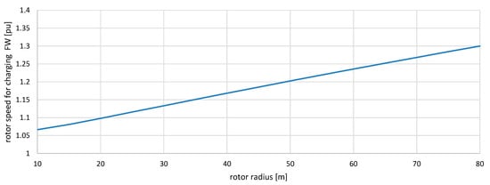
Figure 2.
Necessary rotor speed for charging the FW with centrifugal forces only. The speed base for converting the rotor speed to per unit (pu) is the speed that leads to rated power.
The three types of loads a WT is exposed to are the aerodynamic, gravitational, and inertial loads [12]. Although the FW can only indirectly impact on the aerodynamic loads, via the motion of the rotor, it can directly impact on the gravitational and the inertial loads. With the power of the electric motors that drive the hydraulic pumps, the FW system can even impact on these loads on both ends of the drive train.
In the following Section 2, the WT model is introduced briefly. Section 3 presents the grid services that can be provided with a WT which is equipped with the FW in its rotor. In Section 4, the possibilities of applying the FW for reducing the stress on the mechanical structure of the WT are discussed and the connection between grid services and mechanical stress is made. Section 5 illustrates the behavior of the FW with respect to the grid and with respect to the WT. For this purpose, a scenario is conceived where the WT is subject to turbulent wind on the one hand, and various grid events on the other hand. Finally, Section 6 summarizes the findings and provides an outlook to the future work on this topic.
2. Methods, Simulation Models and Data
2.1. WT Simulation Model and FW Type
The study presented in this paper is based on simulations. The simulation model applied is the first eigenmodes simulation model of a WT [13]. To facilitate reproducibility, the signal names and parameter names mentioned in this paper are provided in the way as they are contained in the source code and hence in the documentation of the simulation model. Hence, although unusual in scientific papers, most of the variable names and parameter names shown in this paper contain underscores, e.g., the generator power is called P_gen. This allows finding a variable or parameter quickly in the model documentation [13]. The WT that is modeled with this simulation model is the NREL 5 MW reference WT [14]. This WT is equipped with a hydraulic–pneumatic FW system that is dimensioned to fit into the rotor blades as designed by Sandia National Laboratories [15]. Of the different conceivable FW configurations, type VI is chosen for the study presented in this paper [16]. The hydraulic–pneumatic piston accumulators are optimized for weight, i.e., they are made of carbon fiber-reinforced plastic. The properties of these piston accumulators determine the additional masses that have to be incorporated in the rotor blades [17]. The design of the pump system for charging the FW, which results in the masses as well as the electrical, mechanical, and hydraulic characteristics, is also published open access [11]. The simulations are conducted with the Matlab and Simulink release 2020a [18].
2.2. Feed Forward Control
The FW is controlled with the control valves, the fluid pressure from the pumps, and the bypass controller. The bypass controller allows fine-tuning the pressure of the pumps by temporarily circulating the fluid pressureless. Hence, whenever the control valves are open, the state of charge is determined by the balance between the pressure in the compressed gas and the fluid pressure [11]. Consequently, the torque from the FW, T_fw, is controllable; and can hence impact on the overall driving torque that acts on the rotor. Eventually T_fw impacts on the power of the generator, P_gen. Figure 3 shows the block diagram of the power control of the WT with FW. In addition, in Figure 3 there is a feed forward control path that enhances the response speed of the FW.
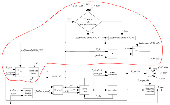
Figure 3.
Simplified block diagram of the power control circuit of the WT with FW system. The red encircled part is the feed forward control.
The feed forward control is introduced here as it is the basis for many of the control functionalities that are introduced in this paper. All functionalities that demand rapid power supply from the FW are facilitated by this feed forward control.
The fundamental idea of the feed forward control is to allow the frequency converter to extract the power from the FW, already as soon as the FW torque has developed. This means that it is no longer necessary to wait until the FW torque managed to accelerate the generator to a different rotational speed, speed_gen. Equation (1) shows that the FW torque, T_fw, is the derivative of the FW inertia, J_fw, with respect to time. J_fw comprises the center of gravity, R_var, of the FW fluid with its mass, m_fw_fluid.
Figure 4 illustrates that T_fw is measured and fed forward to the power controller of the frequency converter, where it is turned into a power offset that is extracted from the generator. This is different from the original power control as published in the model documentation [13]. Hence, T_fw acts simultaneously on the driving end of the drive train (the WT rotor) and on the output end of the drive train (the generator). The advantage of this feed forward control is twofold: (i) The power from the FW can be provided much faster, i.e., without having to overcome the inertias in the drive train first; (ii) the drive train remains in a steadier operating point, because the flexibility of the drive train (illustrated in Figure 4) is less excited to vibrations with every change in T_fw.
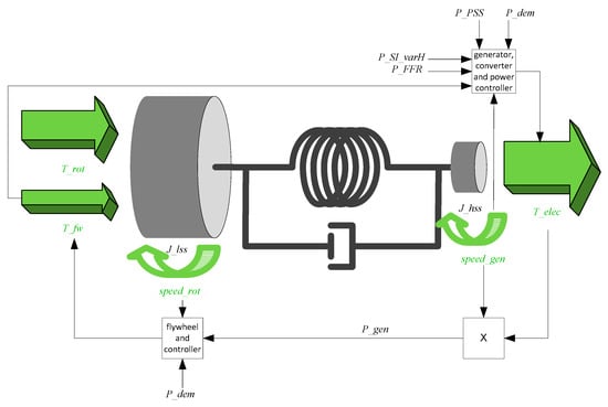
Figure 4.
Simplified drive train model of the WT with the power control and a qualitative illustration of the resulting torques that act on the masses of the drive train.
All variables and parameters shown in Figure 3 and Figure 4 are either introduced in this text, or they are described in detail in the documentation of the simulation model of the WT [13], or of the pump bypass controller [11]. The power demand offsets P_FFR, P_SI_varH and P_PSS are discussed in Section 3.2.1, Section 3.2.2 and Section 3.3, respectively.
In steady-state operation, the power setpoint for the frequency converter, P_setpo_add, results from the rotational speed of the generator, speed_gen, i.e., P_setpo_add = P_setpoint. Whenever the feed forward control path makes the frequency converter extract an amount of power that does not fit the current generator speed, P_fw_add, the power that is fed back into the power control loop, P_feedback, has to be adapted. Otherwise, the power controller would eliminate the additional power as quickly as it can. Therefore, whenever feed forward is active (feedforward_OFF0_ON1 = 1), the feedback power is not the measured generator power, P_gen, but the power that fits the current generator speed, P_setpoint. The ramp rate limiter in the feedback path limits the transients in the fed back power to +/−0.3 pu, which was necessary to avoid undue transients whenever the switch selects a different feedback power.
3. Grid Services
There are many different grid services demanded from WTs. Here, only grid services that are related to active power are discussed, as the FW is an energy storage. Any grid services that are related to reactive power are not in the scope of this work, because reactive power can be provided with the frequency converter alone.
3.1. Steadying Power Infeed
Steadying the power infeed of the WT with the FW, but without feed forward control, has been proposed in the past already [10]. For the NREL 5 MW WT equipped with a FW type VI, a controller design was conducted and the benefit in terms of increased wind energy yield was assessed [11]. In the article at hand, steadying the power infeed is enhanced with the feed forward control, which increased the response speed of the FW. Hence, energy flow direction in the FW can be changed within seconds, which allows the power infeed to be steadied even in high-frequency turbulences and in the case of low-frequency mechanical vibrations in the WT.
Figure 5 shows the behavior of the WT, which applies the FW with the feed forward control as shown in Figure 3 and Figure 4 for steadying the power infeed. Energy is stored in the FW whenever the operating point of the WT suffices for rated power to be fed into the grid. Whenever there is a dip in the wind speed, the FW is discharged to mitigate the dip in electric power infeed. Figure 5 shows wind speed, v_wind, pitch angle, theta, rotor speed, speed_rot, and generator power, P_gen. Figure 6 shows the state of charge of the FW in the three different blades of the WT. The state of charge of the FW is quantified by the radius at which the center of gravity of the FW fluid rotated in the WT rotor: R_var_bl1, R_var_bl2, R_var_bl3 for blade 1, blade 2, and blade 3, respectively. Figure 6 reveals that the state of charge is equal in blade 2 and blade 3, but that it is different from the state of charge of blade 1. This is for balancing the rotor, which is further discussed in Section 4.2.
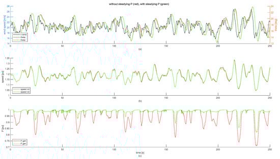
Figure 5.
Simulation of WT operation around full load in normal operation and when the FW is used as short-term energy storage to steady the power infeed. (a) Wind speed and pitch angle. (b) Rotor speed. (c) Generator power.
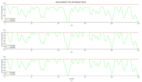
Figure 6.
State of charge of FW in the different blades in normal operation and when steadying the power infeed. (a) Blade 1, (b) blade 2, (c) blade 3.
The FW is designed to achieve about 10% of the rated power of the WT. Hence, the overall energy yield is increased, because the FW can mitigate power dips by approximately 10%. In the scenario shown in Figure 5, the wind speed varies with a turbulence intensity of 0.093, as derived by Equation (2) [19]. In Equation (2) σwind = 1.8758 m/s is the standard deviation and vmean = 20.1795 m/s is the average wind speed, both of the whole simulation period.
In this scenario, steadying the power infeed with the FW increases the energy yield by 3.0987%. This is the same scenario that was previously simulated without the feed forward control, where only an additional energy yield of 0.6133% could be achieved [11]. Hence, direct comparison shows that the feed forward control causes a 2.4854% increase in energy yield.
Apart from the increased energy yield, the steadier power infeed is advantageous for the grid as it reduces flicker from voltage variations and it enhances the utilization of the installed grid equipment [20]. Table 1 lists the benefits for the grid in absolute values and in percentage difference comparing steadying operation with non-steadying operation. The most obvious difference of steadying power infeed is the reduced power variability. The standard deviation of the WT power is reduced by 60.7318% as the FW manages to keep the power infeed close to rated power most of the time. The remaining standard deviation of the power is mainly caused by deeper power dips, because the FW only manages to mitigate power dips by 10% of the rated power of the WT.

Table 1.
Variables quantifying the grid effect of steadying power infeed.
Figure 5 further reveals that steadying the power infeed also reduces the excursions in the rotor speed and in the pitch angle. This mitigation of mechanical stress is further discussed in Section 4.1.
3.2. Grid Frequency Support
3.2.1. Fast Frequency Response
In this section the support of the grid frequency, f_grid, with active power from a WT is discussed. To avoid confusion the terminology shall be introduced first. It has to be noted that different, and in some cases contradicting, terminology can be found in the literature. In this paper, the convention used by Eriksson et al. is applied. Hence, fast frequency response (FFR) refers to power adaptations based on grid frequency deviations. Inertial behavior of a WT, i.e., power adaptations in response to frequency changes, is called inertial response. The resulting energy exchange is called synthetic inertia (SI) [21]. In this section, FFR is applied according to the requirements stipulated for the Canadian grid in Quebec [22]. It is particularly important to note that in this grid code the response to frequency deviations is called inertial response. To avoid confusion, in the paper at hand the author applies the terminology FFR instead.
Hydro Quebec demands WTs to inject a minimum power for a minimum duration and with minimum ramp rates if the grid frequency drops below a certain threshold. However, FFR operation is only demanded in case of sufficient wind speed [22]. The FFR controller applied here exceeds all minimum requirements as stipulated by Hydro Quebec, see Figure 7. This type of FFR is most suitable for generators with small energy storages, such as a WT which can access its kinetic energy in the drive train, or even better, a WT with a FW in its rotor.
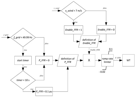
Figure 7.
Flow chart of the FFR controller.
The alternative would be to apply a droop characteristic. In the case of dropped grid frequency a droop characteristic calls for a power increase for a potentially long time, which cannot be realized with the kinetic energy stored in a WT. Hence, precautious downregulation of the WT would be the only way of complying with such a requirement [23]. This approach potentially leads to very large losses in wind energy yield and is therefore not considered here.
Although Hydro Quebec operates a 60 Hz grid, the requirement can be adapted to 50 Hz grids. The threshold for activation of FFR is set to −10 mHz, which also complies with the restrictive Irish grid code [24].
In part-load operation, the extra power, which the WT has to feed into the grid for FFR, is taken from the FW. While the FW generates the extra mechanical power, the feed forward control makes the frequency converter at the terminals of the generator to simultaneously feed the same amount of power into the grid. Hence, the impacts on the rotational speed of the WT, and also on the variation of the drive train loading, are minimized, as seen in Figure 4.
3.2.2. Continuous Inertia Provision
The changes in the grid frequency are quantified by the Rate Of Change Of Frequency (ROCOF). When a WT adjusts its power to the ROCOF, it behaves similarly to synchronously connected rotating machine. Hence, it behaves inertial in a deliberately controlled manner, i.e., it provides inertia not inherently, but synthetically [21]. Hence, it emulates real inertia, which is a way for grid operators to maintain controllability of the grid frequency, even in the case of high penetration with wind power [23].
In this study, the previously proposed variable inertia constant (Hvar) controller is applied [25]. The Hvar controller takes the needs of a variable speed WT and the needs of the grid into account. On the one hand, a WT is bound to be exposed to varying wind speeds; on the other hand, the grid requires reliable inertia provision. The Hvar controller ensures reliable inertia provision by the WT even in case of turbulent wind. However, to consider the worst-case scenario for the stress on the WT, the facility for preventing excessive vibrations caused by the Hvar controller is omitted [26]. Hence, the Hvar controller depicted in Figure 8 results.
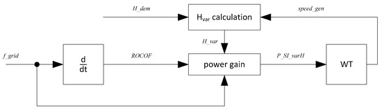
Figure 8.
Block diagram of the Hvar controller.
In the case of normal grid operation with moderate ROCOF, the Hvar controller used only little energy as the sign of the power varies frequently. The frequency spectrum of the ROCOF shows that it is dominated by high frequencies [26]. Hence, the Hvar controller taps the FW only in the case of large and long lasting ROCOF; otherwise, it used the kinetic energy stored in the rotation of the drive train, as seen in Figure 3 and Figure 4.
3.2.3. Frequency Support Simulation
The grid frequency support mechanisms introduced in Section 3.2.1 and Section 3.2.2 target different grid quantities, namely the grid frequency and the ROCOF. However, since they strive for the same goal, i.e., maintaining a healthy and controllable grid frequency, these mechanisms are simulated and assessed together.
For the purpose of testing the functionalities, a part-load operating point of the WT is considered. Full load is less interesting, as there the wind speed usually contains sufficient kinetic energy; hence, the FW is not needed for producing extra power. To have a realistic test case, the reference incident as defined by the European Network of Transmission System Operators for Electricity (ENTSO-E) [27] is chosen, as seen in Figure 9a. To improve comprehensibility, the scenario shown in Figure 9 considers a non-turbulent constant wind speed of 11 m/s.
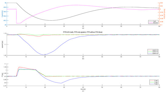
Figure 9.
Simulation of WT operation providing the grid with FFR and SI in response to the ENTSO-E reference incidence. (a) Grid frequency and ROCOF. (b) Rotor speed. (c) Generator power.
To facilitate assessing the behavior of the WT with FW, Figure 9 shows three cases: (i) FFR and SI as described above, (ii) FFR as described above only, and (iii) FFR without applying the FW. The latter scenario represents the situation of a state-of-the-art WT, which taps kinetic energy from its drive train to provide the grid with extra power.
Figure 9 shows clearly that the FW prevents large excursions in the rotational speed. Hence, the recovery phase, which is clearly visible in the case of FFR without FW, can be avoided. The recovery phase is particularly disturbing for the grid, as it deprives the grid of power in a situation when it is in desperate need of extra power. The demanded inertia constant for the Hvar controller is set to Hdem = 12 s, as in previous studies [26].
3.3. Power System Stabilization
An alternating current (AC) grid can be considered a large rotating machine. In the steady state, the magnetic stator fields of all synchronously connected motors and generators rotate at the same rate. The connection between these motors and generators are the electric lines and cables. The rotating mechanical masses are linked with the electric lines via the magnetic field in the airgaps of the motors and generators. This configuration, together with the fact that AC grids in many countries spread large distances and comprise large numbers of synchronously connected machines, leads to the problem that AC grids are prone to electro-mechanical oscillations. Such oscillations are tackled with power system stabilizers (PSS), which are typically incorporated in the excitation systems of synchronous generators [28]. Although in the steady state the excitation system of a synchronous generator determines the reactive power production, a transition from one state of excitation to another also leads to a transient in active power production of the same synchronous generator. With this temporary variation of active power, periodic rotor speed oscillations in synchronous generators can be damped. Damping, D, is torque, T, in phase with speed oscillations, ω, as seen in Equation (3).
Hence, the same concept can be transferred to any other generator, e.g., a WT, which must provide the grid with active power, P, that is oscillating in phase with the grid frequency oscillations.
This concept has been proposed in the past already for the application of fixed speed WTs, which can vary their power output solely with the pitch angle [29]. The performance of PSS in fixed speed WTs was assessed with simulations of electro-mechanical oscillations in the Nordic grid [30]. The concept of PSS in a synchronous generator was adapted to variable speed WTs with frequency converters, where the DC capacitor voltage was controlled similarly to the excitation control in a synchronous generator [31]. In addition, other methods of PSS with WTs are conceivable [32]. However, all of these methods have in common that they have to extract active power, P, from the grid in case f_grid swings beyond its steady-state value, f_grid_ss, and that they have to inject extra P in case f_grid swings below f_grid_ss. The WT manufacturer Nordex emulated PSS behavior with variable speed WTs by periodically varying the reactive power infeed. The obvious advantage of this approach is that WTs can provide PSS independently of the wind speed [33]. The damping effect in the grid is caused by the resistances of lines and cables, which act as braking resistors when the injected reactive power flows through them.
The frequencies of electro-mechanical oscillations can vary in a wide range. In the study on the Nordic grid, the observed frequencies in the different locations ranged from 0.3 Hz to 0.8 Hz [30]. The tests with the aforementioned Nordex WTs were conducted in the Finnish grid and there, the grid oscillations to be tackled are in the range of 0.6 to 1 Hz [33]. In general, the frequency of electro-mechanical grid oscillations is in the range of 0.1 to 0.7 Hz when considering inter-area oscillations. The frequencies of local grid oscillations can be expected to be above that and in the range of 0.7 to 2 Hz, while oscillations of single machines are typically with frequencies of above 2 Hz [32].
Since electro-mechanical grid oscillations are grid frequency oscillations, it could be suspected that PSS is identical with FRR or SI. However, neither is the case, as FRR responds only when a certain frequency threshold is exceeded, while grid oscillations can threaten system stability even if their magnitude seems harmless. SI, on the other hand, responds to the ROCOF. Hence, its power, P_SI_varH, is 90 degrees out of phase to the grid frequency oscillations, which is why it does not contribute to damping.
Figure 10 shows that the power offset for damping grid oscillations, P_PSS, is derived from the difference between the instantaneous f_grid and its steady state value, f_grid_ss, around which it oscillates, see Equation (4).
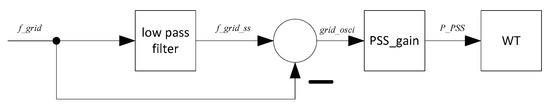
Figure 10.
Block diagram of PSS.
In the study at hand, P_PSS is realized with the FW in the WT. The FW is particularly handy for this purpose because it allowed for periodic energy storage and release without much impact on the rotational speed. The alternative to using the FW would be to use the kinetic energy stored in the WT drive train, which would invariably lead to noticeable speed excursions. Also for PSS, the feed forward control is applied. It mitigates transients in the loading of the drive train, because also here it varies the power on the rotor end and on the generator end simultaneously, as seen in Figure 4. Since the kinetic energy used for PSS is not taken from the rotation of the drive train, there is also hardly any impact on the rotor speed, and, hence, on the aerodynamics and consequently on the energy yield of the WT, as seen in Figure 11.
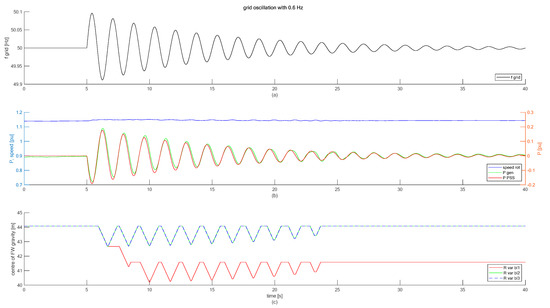
Figure 11.
Simulation of PSS with the WT when subject to grid oscillations with a frequency of 0.6 Hz. (a) Grid frequency. (b) Rotor speed, generator power and power setpoint for PSS. (c) Centre of gravity of FW fluid in the three blades.
The simulation shown in Figure 11 is also conducted with a non-turbulent constant wind speed of 11 m/s. The gain, which translates the grid frequency excursion to power setpoints in pu is PSS_gain = 2 pu/Hz. Figure 11c shows the state of charge of the FW with the variable R_var for the different blades. This diagram reveals that the rotor is not balanced in the beginning. With the first operation of the FW, it becomes balanced and from there onwards it maintains an asymmetric state of charge to level out the imbalance in the rotor. This is further discussed in Section 4.2.
3.4. Low Voltage Ride Through
From the perspective of the grid, low voltage ride-through (LVRT) is an important functionality of generators. Transient voltage drops, e.g., caused by lightning strikes on overhead lines, contamination of insulators, or faulty grid equipment, occur regularly. Usually, they do not last for more than several hundred milliseconds and are automatically cleared by the protection system in the grid. Therefore, power consumers are hardly affected by transient voltage drops, i.e., they stay connected to the grid. Hence, in order to avoid a potentially dangerous imbalance between generation and demand, generators also have to stay connected. For generators, transient voltage drops are a large burden, because they can export only less or even no electric power while the voltage is low. During a transient voltage trough, generators have to accumulate the mechanical driving power. WTs do this by storing the kinetic energy in the acceleration of their drive trains. Since this can lead to dangerous overspeeds, i.e., wear and tear and disconnection from the grid, both the owners of WTs and the grid operators fear the consequences of transient voltage drops.
In a WT, the acceleration can be mitigated with quick pitching of the rotor blades. This limitation of the rotational speed comes at the price of harmful variations of the aerodynamic thrust, which causes fatigue, mainly in the WT tower [34]. Some WTs also try to mitigate mechanical loads by applying braking resistors in order to dissipate some of the driving power while the grid voltage is low.
The FW in the rotor of a WT can also absorb energy during LVRT; however, it can do so even on both ends of the drive train. While the FW is charged, the Coriolis forces that arise from moving the fluid mass to a larger radius cause a decelerating torque in the rotor blades. However, since charging is accomplished with motor-driven pumps, the power that these pumps absorb has to be produced by the generator. Hence, although the generator cannot feed power into the grid, it can produce some decelerating torque from the electric power that it provides for the pumps. Figure 12 shows, again, the schematic of the drive train. It shows how the FW torque, T_fw, and the electric torque, T_elec, caused by the pumps in the generator, mitigate the acceleration of the WT drive train.
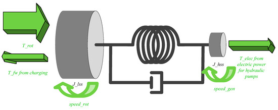
Figure 12.
Schematic of the drive train, where the FW is charged during LVRT.
Apart from the mitigated acceleration, Figure 12 reveals another advantage of charging the FW during LVRT: The flexibility of the drive train is not unloaded entirely. Therefore, LVRT excites the drive train less to vibrations. If the WT is burdened less with overspeed and vibrations, it can resume power infeed quicker after the voltage has recovered. Hence, the FW helps the WT to be a reliable source of power, also in the case of transient voltage drops.
To illustrate the behavior of the WT with FW, Figure 13 shows a simulation of a voltage drop that leads to zero active power in all three phases and that lasts for 500 ms [34].
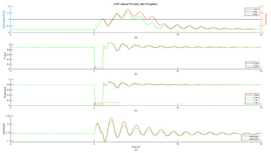
Figure 13.
Simulation of LVRT. (a) Wind speed and pitch angle. (b) Generator power. (c) Generator torque and negated FW torque. (d) Generator speed.
The scenario shown in Figure 13 is simulated with a constant non-turbulent wind speed of 11 m/s. To assess the effect of the FW, the scenario is simulated twice, once without applying the FW and once with charging the FW to mitigate the acceleration caused by the transient loss in grid power. Figure 13 shows that the FW mitigates the acceleration, which can be seen in the generator speed, speed_gen, and in the pitch angle, theta, with which the WT tries to bring the speed back to a steady state. Figure 13c shows the generator torque, T_elec, and the FW torque, T_fw (T_fw is negated for better visibility in the diagram). While the FW was charged, T_fw decelerates the rotor. At the same time, the pumps for driving the fluid into the accumulators close to the blade tip absorb power from the generator, which leads to T_elec that mitigates the acceleration of the generator.
4. Stress Reduction
The aforementioned grid services decouple the electric power that the WT feeds into the grid from the prevailing wind at the rotor. This is a potential source of stress for the structure of the WT. However, the FW is not only good for providing grid services, but since it contains movable masses in the driving end of the drive train, it can also be used for mitigating stress.
The method to achieve the goal of stress reduction in the WT is to steady the operation as far as somehow possible. The three types of loads on a WT are aerodynamic, gravitational, and inertial loads [12]. These loads cause stress for the mechanical structure of the WT and they are caused by the deflection of the WT components and acceleration of the masses in the WT components. Both lead to forces, either static or cyclic, which act on the structure of the WT components. These forces arise from the ambient wind, the rotation of the rotor, and vibrations in WT components. Hence, in order to reduce such forces, their causes should be eliminated as far as possible. It is obvious that the ambient wind has to be taken as it is. The rotation of the rotor is desired, and hence, cannot be avoided. However, the centrifugal acceleration, as well as the gravitational acceleration can be mitigated by the movable masses of the FW. In addition, the accelerations from vibrations in WT components can be mitigated by avoiding resonances [10] and by actively damping vibrations.
All this is a kind of steadying of the WT operation. If the operation of a WT is steady, i.e., if ideally all rotational speeds are constant and if the deflection of flexible WT components is also constant, then the stress on the structure of the WT is minimal. Consequently, in the following subsection, steadying the power infeed with the FW is assessed from the point of view of the WT structure.
4.1. Steadying Power Infeed
In the scenario in Section 3.1, the WT steadied its power infeed with the FW, which, at the same time, also steadied the operation of the whole WT. Hence, in addition to the signals shown in Figure 5 and Figure 6, Figure 14a shows the out-of-plane speed of the tip section of exemplary blade 1. The out-of-plane speed is a measure for the changes in the operating point, which constitutes itself in changes in the aerodynamic thrust. The same reasoning applies to the longitudinal speed of the nacelle (tower head), which is shown in Figure 14c. Finally, Figure 14b shows the in-plane speed of the tip section of exemplary blade 1, which can be compared to the rotor speed signal in Figure 5.
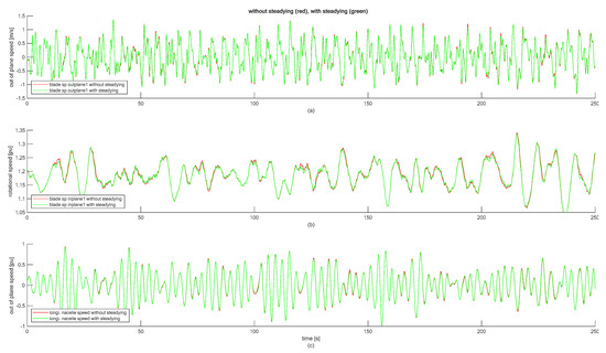
Figure 14.
WT component speeds in normal operation and when steadying the power infeed with the FW. (a) Out of plane speed of tip section of blade 1. (b) In- plane speed of tip section of blade 1. (c) Longitudinal speed of nacelle.
All signals in Figure 5 and Figure 14 show that the WT experiences equal or slightly lower component speeds when the power infeed is steadied with the FW. This is remarkable as the WT is loaded to a somewhat higher level (more energy yield, see Table 1).
Whenever the aerodynamic power at the rotor of the WT suffices for more than rated power, the electric pumps start charging the FW. The electric power consumed by the pumps creates a decelerating torque in the generator of the WT, which mitigates the negative damping in full-load operation. In normal full-load operation, WTs limit their power infeed to rated power. Any transient increase in wind speed leads to a transient increase in rotational speed, while the power is kept constant at its rated value. Hence, in transient speed increases of the generator, the torque decreases. This is negative damping, which is generally known to be a potential source of vibrations in full-load operation.
4.2. Balancing Rotor
Virtually no WT is entirely free of imbalances. Tolerances in the manufacturing of rotor blades, imprecisions in the balancing process at commissioning of a WT, contaminations inside a blade or on the surface of a blade, damages in the structure of a rotor blade, as well as repairs during the service life of a blade can lead to imbalances of a WT rotor. Imbalances of this sort can occur at any time during the lifetime of a WT and are a driver of fatigue. However, imbalances in the rotor can be leveled out with the FW. For this purpose, the state of charge of the FW in the three blades can be adjusted such that the existing inertia imbalance in the blades is compensated. This leads to a ratio of states of charge in the three blades, which has to be maintained at all times. Figure 6 and Figure 11 show examples of how the different states of charge are maintained as soon as the FW leaves its initial operating state. This method is applied in all control options presented in this paper. Therefore, its implications are outlined here, but it has to be kept in mind that they have a bearing on all other sections of this paper. While the effect of the FW in terms of torque and rotation is well documented already [7,10], the kinetics of the FW beyond the rotation of the rotor shall be discussed in more detail here.
Figure 15 shows a qualitative representation of the FW in an asymmetric state of charge. The different radii of center of gravity of the hydraulic fluids in the different blades lead to different centrifugal forces. While different centrifugal forces cause fatigue in the rotating part of the WT, Figure 15 also shows the horizontal components of the different centrifugal forces, because they excite the WT tower to lateral (side-to-side) vibrations.
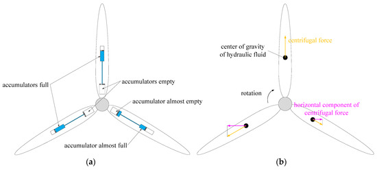
Figure 15.
FW in asymmetrical state of charge for leveling out imbalances in the rotor. (a) Schematic of the asymmetrically filled piston accumulators in the rotor blades. (b) Qualitative representation of the centrifugal forces exerted by the FW fluids.
HYDAC Technology GmbH holds a patent on the methodology of balancing the rotor with the FW when an unknown imbalance has developed during the operation of the WT [35]. In the following, the equations are presented, that allow finding the states of charge for leveling out a known imbalance analytically.
In the model an imbalance in the rotor is introduced by an additional mass in blade 1: m_bladetip1 > m_bladetip2 = m_bladetip3. These parameter names and their values can be found in the documentation of the simulation model [13].
The inertia of blade 1, J_blade1, comprises the blade root mass, m_bladeroot, and the blade tip mass, m_bladetip1, with their distances to the center of rotation, R_cntr_gravi_bladeroot and R_cntr_gravi_bladetip, respectively, as seen in Equation (5).
Extending Equation (5) to also represent the FW in charged state leads to Equation (6), where R_fw_max_bl1 and m_fw_fluid are the maximum permissible center of gravity of the fluid in blade 1 and the fluid mass in one blade, respectively.
The inertias of blade 2 and blade 3, J_blade2 and J_blade3, respectively, are derived likewise. The goal is to get equal inertias in all three blades: J_blade1 = J_blade2 = J_blade3. These equal inertias allow resolving Equation (6) for R_fw_max_bl1.
The other two blades, i.e., the lighter blades, can charge their FW accumulators to R_fw_max, which represents the maximum filling level of the FW system [13].
The same methodology can be applied for finding the minimum charging level. Obviously, blade 1 may be discharged to the minimum filling level, R_fw_min_bl1 = R_fw_min, while the FW in blade 2 and blade 3 has to maintain a higher charging state to level out the imbalance in the blade inertias.
The simulations conducted in this paper are all done with an imbalance in the rotor: The inertia of blade 1 is 1.37% larger than the inertia of blade 2 and blade 3. This imbalance leads to asymmetric centrifugal forces, which cause lateral deflections of the WT tower. The scenario shown in Section 3.1 and Section 4.1 are again taken here to show the effect of this rotor imbalance. When the WT steadies the power infeed with the FW, the FW starts with striving for the state of charge ratio, which levels out the imbalance in the rotor, as seen in Figure 16. The effect is visible in Figure 16, which shows that the lateral tower vibrations decrease with time when the FW levels out the imbalance, while they increase if the imbalance remains in the rotor.
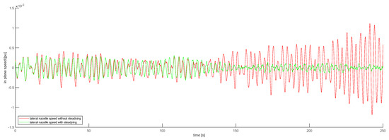
Figure 16.
Lateral WT tower vibrations in normal operation and when steadying the power infeed with the FW.
4.3. Mitigating Excitations from Gravitation and Wind Shear
Wind shear leads to different thrust forces in the different blades. An imbalance in thrust forces causes a tilting torque at the tower top, which can be mitigated with the FW; see Figure 17a. If the state of charge of the FW is varied in a way that the blade, which experiences less thrust, exerts more centrifugal forces, the tilting torque can be mitigated. The tilting torque leads to stress in the tower and excites it in its second eigenmode. In contrast to the balancing of inertias discussed in Section 4.2., mitigating tilting from wind shear is not static but has to be performed continuously. Hence, if this control functionality is desired, the FW has to asynchronously vary its state of charge in every rotation of the rotor.
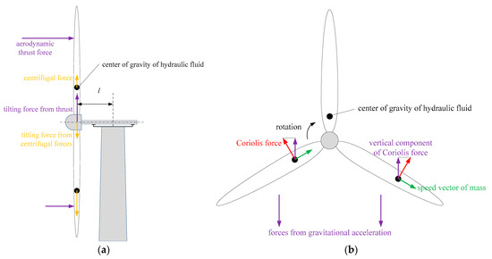
Figure 17.
Continuous asymmetric operation of the FW can mitigate stress from wind shear and gravitation. (a) Asymmetric centrifugal forces can mitigate the tilting of the tower head by offsetting differences in thrust from, e.g., wind shear. (b) Asymmetric Coriolis forces from moving the FW fluid can offset the gravitational forces that act on the rotor blades.
Another example of stress reduction with the FW is the mitigation of the influence of gravitation on the blade root bending torque. The torque that acts on the blade root is dominated by the gravitational acceleration on the blade masses. Figure 17b shows that the Coriolis forces, which occur whenever the FW fluid is moved while the rotor rotates, can be controlled such that the forces from gravitation are partially offset. The Coriolis forces from the FW are obviously only a minor fraction of the gravitational forces. However, the direction of the blade root bending torque alters with every rotation of the rotor, which is a major cause for fatigue. Hence, every reduction of this torque can save lifetime.
Both control options introduced in this subsection rely on continuous asymmetric operation of the FW. This seems to contradict the desire to balance the rotor with the FW as introduced in Section 4.2. However, if the ratio of the states of charge is maintained also here, then an imbalance in the rotor is leveled out and the impact from wind shear or gravitation is counteracted nonetheless.
Taking the example of mitigating blade root bending from gravitation and analyzing the Coriolis forces over a whole revolution of the rotor reveals that a constant force in lateral direction results. Hence, there is no periodic excitation that could lead to vibrations of the tower. Figure 18 shows the operation of the WT at a constant non-turbulent wind speed of 11.5 m/s, where the WT runs at rated speed. The states of charge of all three blades are shown in Figure 18a. But since the effect is identical in all three blades, only the blade root torque of blade 2, T_drive2, is shown in Figure 18b. The FW reduces the peak-to-peak value of T_drive2 by 7%.
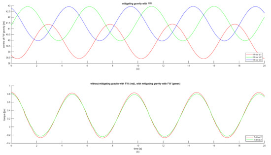
Figure 18.
Continuous asymmetric operation of the FW to mitigate the gravitational forces that lead to the torques which act on the blade roots. (a) Centre of gravity of FW fluid in the three blades. (b) Blade root torque of blade 2.
The excitation from wind shear is similar deterministic as the excitation from gravitation. However, it is obviously not possible to apply both control options at the same time. Hence, for every particular WT and its site, it has to be determined which effect causes the most fatigue and therefore has to be mitigated with the FW. Roughness length of the terrain around the WT, height of the tower, and lengths of the blades are among the criteria that influence this decision.
4.4. Damping In-Plane Vibrations of Blades and Tower
The FW can also be used for damping in-plane vibrations of the WT tower or of individual rotor blades. Also here the FW has to be controlled in a way that the Coriolis forces either counteract the lateral motion of the tower, or the in-plane motion of one rotor blade. To show an example, the latter case is considered: The LVRT simulation shown in Figure 13 also led to strong in-plane vibrations of the rotor blades. Figure 19 shows the scenario again, once with mitigating the acceleration only (as discussed in Section 3.4), and once where in addition also the in-plane vibrations of the blades are damped.
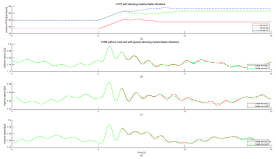
Figure 19.
Simulation of LVRT with and without damping in-plane motion of the blades. (a) Centre of gravity of FW fluid in the three blades. (b) In-plane speed of tip section of blade 1. (c) In-plane speed of tip section of blade 2. (d) In-plane speed of tip section of blade 3.
Figure 19 shows that the in-plane vibrations of the blades calm down quicker when they are actively damped with the FW. The damping of these vibrations starts at 6.5 s. Before 6.5 s, the mitigation of acceleration is still active (see Section 3.4). In an operating point where the acceleration does not lead to speeds beyond rated speed, the damping of in-plane blade vibrations could start already at the voltage recovery (5.5 s), which would improve the damping result even further.
4.5. Emergency Braking
In case a WT experiences a problem, it has to be brought to standstill. One of the most severe problems a WT can encounter is a permanent grid voltage drop, also called grid loss. In such a situation, the torque of the generator gets lost instantaneously. The WT has to be brought to standstill with the aerodynamic brake, i.e., by pitching the blades to feather position. The advantage of this method is that the driving torque gets eliminated and the decelerating torque gets generated at the same end of the drive train. The disadvantage is that fast pitch angle variations at high rotor speeds lead to drastic thrust variations, which are a heavy burden for the support structure of the WT, mainly for the tower. Figure 20 shows the worst-case scenario, in which the WT runs at 11.5 m/s wind speed, which leads to the maximum thrust in downwind direction. When the grid connection gets lost at 5 s, the speed controller tries to limit the acceleration and brings the rotor to a harmless idling speed. This is done by running the pitch angle with the maximum pitch rate towards feather position. The scenario is simulated with and without charging the FW to support the braking procedure. Similar to the LVRT scenario, the FW can also here mitigate the acceleration on both ends of the drive train, as seen in Figure 12. This has two advantages for the WT: (i) The negative thrust, which in the beginning of the braking procedure excited the tower heavily to longitudinal fore-aft vibrations, is also reduced, see Figure 20c; (ii) the maximum overspeed is reduced, which reduces the centrifugal acceleration (Figure 21c). The longitudinal tower vibrations shown in Figure 20b are only lightly damped because of the large pitch angles.
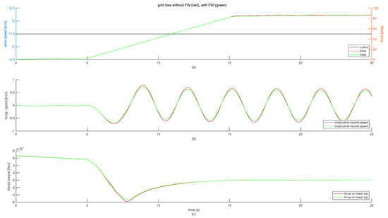
Figure 20.
Emergency braking after grid loss. Effect on the WT tower, with and without the support of the FW. (a) Wind speed and pitch angle. (b) Longitudinal nacelle speed. (c) Thrust torque acting on tower top.
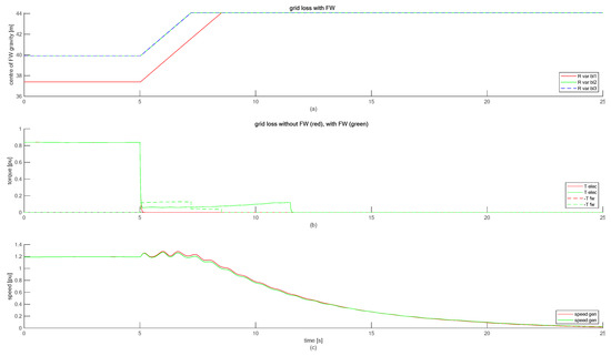
Figure 21.
Emergency braking after grid loss. Effect on the drive train of the WT, with and without the support of the FW. (a) Centre of gravity of FW fluid in the three blades. (b) Generator torque and negated FW torque. (c) Generator speed.
Figure 21 shows that the FW produces a decelerating torque until the FW reached its maximum state of charge in all three blades. As the FW gets charged by the pumps, their electric power is produced by the generator, which causes a torque in the generator, as seen in Figure 21b. The pumps remain turned on and produce losses, even after the FW is fully charged, until the generator underruns its minimum speed for power production.
Figure 21c shows that the generator speed accelerates less when the FW supports the braking procedure. Since the WT is brought to a standstill, the vertical axis prevents the full extent of this effect from being easily visible.
5. Results
To assess the effect of the FW, a test scenario is presented in this section, as seen in Figure 22. This test scenario is a mixture of the circumstances already discussed in the previous sections. The WT is subject to the same turbulent wind speed as shown in Figure 5. At 65 s, the grid frequency contains an event of electromechanical oscillations as shown in Figure 11, which is assumed to be caused by a switching event in the grid [33]. At 140 s, the ENTSO-E reference incident, as shown in Figure 9, follows, which is assumed to be caused by a major loss of generation in the grid [27]. Furthermore, transient voltage drops at 25 and 130 s, which prevent active power infeed for 0.5 s each (see Figure 13), are considered [34]. Eventually, the grid connection is permanently lost at 250 s, forcing the WT to perform an emergency braking.
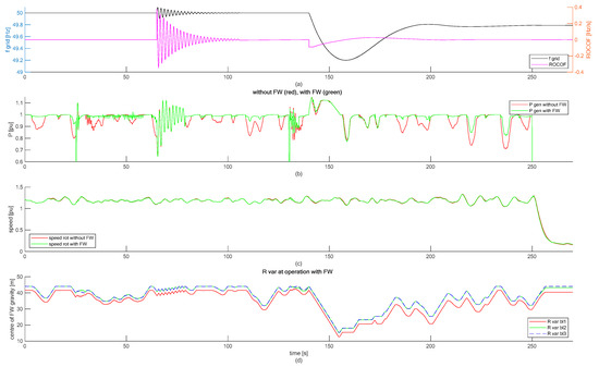
Figure 22.
Scenario for testing the different functionalities. (a) Grid frequency and ROCOF. (b) Generator power. (c) Rotor speed. (d) Centre of gravity of FW fluid in the three blades.
Obviously, not all control options that are introduced in the sections above can be activated at the same time. Consequently, the scenario shown in this section applies steadying power infeed, FFR, SI, PSS, LVRT, balancing the rotor, damping in-plane vibrations of the blades, and emergency braking whenever necessary. The mitigating of the gravitational impact on the blades is deactivated as the scenario is too congested with excitations from the grid. Hence, steady-state operation of the WT, which is where mitigating the gravitational impact on the blades makes most sense, hardly ever takes place.
Table 2 shows that the FW increases the energy infeed by 2.7113%, which is less than in the power-steadying scenario considered in Table 1. This is hardly surprising, as the FW has to deal with a lot of different tasks here, while it is only demanded to steady the power infeed in the scenario shown in Section 3.1.
Table 2.
Variables quantifying the grid effect of the WT in the test scenario.
The standard deviation of the power, also shown in Table 2, is clearly dominated by the voltage drops; hence, a comparison is hardly meaningful. The power demand offsets for FFR, SI, and PSS are as discussed above. However, the power that is actually generated by the generator, P_gen, is also influenced by its rotational speed, which in turn is influenced by the turbulent wind. Therefore, during PSS and grid frequency support, the time trace of P_gen in Figure 22b looks different from the time traces shown in Figure 11 and Figure 9, respectively.
The stress on the mechanical structure of the WT is assessed with the histograms of some selected mechanical quantities in Figure 23. When considering the stress on the WT, most emphasis should be put on the tower and the rotor blades, as these are the most expensive components of a WT [19]. For each signal, Figure 23 compares the operation of the WT in the test scenario without FW (red) and with the FW (blue).
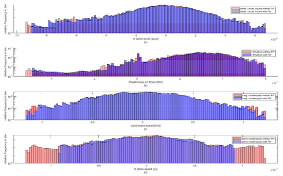
Figure 23.
Effect of the test scenario on the mechanical structure of the WT, quantified with histograms of (a) in-plane acceleration of the tip section of blade 1, (b) thrust torque acting on the tower top, (c) longitudinal speed of the nacelle and (d) lateral speed of the nacelle.
The acceleration of the blade tip masses is very similar in the two cases; see Figure 23a. The FW reduces the largest thrust peaks that act on the tower head; see Figure 23b. The large positive thrust is mainly driven by instances of high rotor speed. The large negative thrusts are caused by the emergency braking initiated at 250 s. The reduction in the extreme thrust values reduces stress in the tower as it reduces the torque that acts on the tower. However, this also has an effect on the cyclic stress quantified by the longitudinal vibration of the tower; see Figure 23c. The most dominant effect, though, is the balancing of the rotor, which allows the FW to level out the inertia imbalance between the three rotor blades in most operating conditions. Whenever there is an imbalance in the rotor, the tower is bound to exhibit lateral vibration. These vibrations are grossly reduced by the FW as it levels out inertia imbalances before vibrations with large magnitudes can develop; see Figure 23d.
6. Discussion, Conclusions and Outlook
This paper shows clearly that a hydraulic–pneumatic FW in the rotor of a WT is suitable for serving the grid as well as the WT itself. The numerous functionalities presented in this paper can be applied as needed. Some of them can be in operation continuously and in combination with others. Some are specifically made for rarely occurring circumstances, are hardly compatible with others, and are hence only activated when needed.
It is shown in this paper that the proposed FW can serve the grid by enhancing the WT to increase the energy yield around full-load operation. This steadying of the power infeed also steadies the operating point of the WT. Hence, it mitigates accelerations of WT components that results from operation in turbulent wind. A steadier operating point reduced the stress on the WT structure.
Apart from steadying the power infeed, the FW enhances the WT to support the grid frequency. Grid codes of different countries demand different functionalities to support the grid frequency. Therefore, it is shown how the FW enhances a WT to provide rapid control power (FFR), continuous grid inertia, and damping of sub-synchronous grid frequency oscillations (PSS). Even riding through transient grid voltage drops (LVRT) is facilitated with the FW, as it reduces the acceleration of the drive train while the grid voltage is low. This is the same benefit for the WT as when the FW is applied for mitigating rotor acceleration in the case of emergency braking. Hence, the FW does not only serve the grid as short-term energy storage. It also reduces the mechanical stress that acts on the structure of the WT.
Even in normal operation of the WT, which means when the grid does not demand any extra functionality, the FW is usable for reducing stress in the WT. The FW can level out imbalances in the rotor. It can mitigate alternating gravitational acceleration that acts on the rotor blades in every revolution of the rotor. It can also mitigate cyclically varying thrust forces from wind shear and it can be applied for damping oscillations of the rotor blades or of the tower in in-plane direction.
The design of the FW as applied in this study can be considered a conservative assumption. It is driven by the space that is available for the piston accumulators inside the rotor blades. Since state-of-the-art piston accumulators must not be bent, the space is limited not only by the geometry of the rotor blade, but also by the bending in the worst conceivable operating condition [16]. Although the piston accumulators considered in this study are designed to be flexible [17], the previously developed FW configuration type VI is applied, i.e., the potential to bend the accumulators is not utilized yet. The motivation for this decision is that it allows using the proven and publicly available rotor blade design by Sandia [15].
The focus of a current research project is on designing a rotor blade from scratch, where the flexible piston accumulators are not only considered to be integral components, but also to be an essential part of the support structure of the blade. With this new design, there will be fewer restrictions on the location of the center of gravity of the FW fluid (R_var), on the fluid volume and its flow speed. Hence, with this blade, the effects that the FW will have on the grid and on the mechanical stress in the WT are expected to be magnified.
Funding
This research was funded by Gesellschaft für Energie und Klimaschutz Schleswig-Holstein GmbH (EKSH), grant number 8/12-29.
Institutional Review Board Statement
Not applicable.
Informed Consent Statement
Not applicable.
Data Availability Statement
The data presented in this study is available in the cited references.
Acknowledgments
The author acknowledges the valuable discussions with the colleagues at the Wind Energy Technology Institute (WETI) of Flensburg University of Applied Sciences.
Conflicts of Interest
The author declares no conflict of interest. The funders had no role in the design of the study; in the collection, analyses, or interpretation of data; in the writing of the manuscript; or in the decision to publish the results.
References
- Srivastava, P.K.; Tiwari, A.N.; Singh, S.N. Impacts of Wind Energy Integration to the Utility Grid and Grid Codes: A Review. Recent Adv. Electr. Electron. Eng. 2020, 13, 446–469. [Google Scholar] [CrossRef]
- Elia, A.; Taylor, M.; Gallachóir, B.Ó.; Rogan, F. Wind turbine cost reduction: A detailed bottom-up analysis of innovation drivers. Energy Policy 2020, 147, 111912. [Google Scholar] [CrossRef]
- Barlas, T.K.; van Kuik, G.A.M. Review of state of the art in smart rotor control research for wind turbines. Prog. Aerosp. Sci. 2010, 46, 1–27. [Google Scholar] [CrossRef]
- Schubel, P.J.; Crossley, R.J. Wind Turbine Blade Design. Energies 2012, 5, 3425–3449. [Google Scholar] [CrossRef]
- Rehman, S.; Alam, M.M.; Alhems, L.M.; Rafique, M.M. Horizontal Axis Wind Turbine Blade Design Methodologies for Efficiency Enhancement—A Review. Energies 2018, 11, 506. [Google Scholar] [CrossRef]
- Zhang, Z.; Fitzgerald, B. Tuned mass-damper-inerter (TMDI) for suppressing edgewise vibrations of wind turbine blades. Eng. Struct. 2020, 221, 110928. [Google Scholar] [CrossRef]
- Jauch, C. A flywheel in a wind turbine rotor for inertia control. Wind Energy 2014, 18, 1645–1656. [Google Scholar] [CrossRef]
- Hippel, S.; Jauch, C. Hydraulic-Pneumatic Energy Storage in a Wind Turbine for Enhancing the Power System Inertia. In Proceedings of the 13th Wind Integration Workshop, Berlin, Germany, 11–13 November 2014. [Google Scholar]
- Jauch, C.; Hippel, S. Hydraulic–pneumatic flywheel system in a wind turbine rotor for inertia control. IET Renew. Power Gener. 2016, 10, 33–41. [Google Scholar] [CrossRef]
- Jauch, C. Controls of a flywheel in a wind turbine rotor. Wind Eng. 2016, 40, 173–185. [Google Scholar] [CrossRef]
- Alhrshy, L.; Jauch, C.; Bünning, N.; Schaffarczyk, A.P. Development of a Lightweight Hydraulic-Pneumatic Flywheel System for Wind Turbine Rotors. WETI Hochsch. Flensbg. 2021. [CrossRef]
- Hansen, M.O.L. Aerodynamics of Wind Turbines, 2nd ed.; Earthscan: London, UK, 2010. [Google Scholar]
- Jauch, C. First Eigenmodes Simulation Model of a Wind Turbine—For Control Algorithm Design. WETI Hochsch. Flensbg. 2020. [Google Scholar] [CrossRef]
- Jonkman, J.; Butterfield, S.; Musial, W.; Scott, G. Definition of a 5-MW Reference Wind Turbine for Offshore System Development. Available online: https://www.nrel.gov/docs/fy09osti/38060.pdf (accessed on 6 January 2021).
- Resor, B. Definition of a 5 MW/61.5 m Wind Turbine Blade Reference Model. April 2013. Available online: https://prod.sandia.gov/techlib-noauth/access-control.cgi/2013/132569.pdf (accessed on 6 January 2021).
- Hippel, S.; Jauch, C.; Ritschel, U. Hydraulic-pneumatic flywheel configurations for controlling the inertia of a wind turbine rotor. Wind Eng. 2019, 43, 114–132. [Google Scholar] [CrossRef]
- Alhrshy, L.; Jauch, C.; Kloft, P. Development of a Flexible Lightweight Hydraulic-Pneumatic Flywheel System for Wind Turbine Rotors. Fluids 2020, 5, 162. [Google Scholar] [CrossRef]
- MATLAB Version: 9.8.0.1323502 (R2020a). Available online: http://uk.mathworks.com/products/matlab/ (accessed on 6 January 2021).
- Schaffarczyk, A. Understanding Wind Power Technology, Theory, Deployment and Optimisation; Wiley: Chichester, UK, 2014. [Google Scholar]
- Jauch, C.; Gloe, A.; Hippel, S.; Thiesen, H. Increased Wind Energy Yield and Grid Utilisation with Continuous Feed-In Management. Energies 2017, 10, 870. [Google Scholar] [CrossRef]
- Eriksson, R.; Modig, N.; Elkington, K. Synthetic inertia versus fast frequency response: A definition. IET Renew. Power Gener. 2018, 12, 507–514. [Google Scholar] [CrossRef]
- Hydro-Québec Technical Requirements for the Connection of Generating Stations to the Hydro-Québec Transmission System. Decision D-2018-145. 1 January 2019. Available online: http://www.hydroquebec.com/transenergie/fr/commerce/pdf/2_Requirements_generating_stations_D-2018-145_2018-11-15.pdf (accessed on 26 January 2021).
- EirGrid; Soni. All Island TSO Facilitation of Renewables Studies. Available online: http://www.eirgridgroup.com/site-files/library/EirGrid/Facilitation-of-Renewables-Report.pdf (accessed on 26 January 2021).
- EirGrid Grid Code. Version 9. 21 December 2020. Available online: http://www.eirgridgroup.com/site-files/library/EirGrid/GridCodeVersion9.pdf (accessed on 26 January 2021).
- Gloe, A.; Jauch, C.; Craciun, B.; Winkelmann, J. Continuous provision of synthetic inertia with wind turbines: Implications for the wind turbine and for the grid. IET Renew. Power Gener. 2019, 13, 668–675. [Google Scholar] [CrossRef]
- Jauch, C.; Gloe, A. Simultaneous Inertia Contribution and Optimal Grid Utilization with Wind Turbines. Energies 2019, 12, 3013. [Google Scholar] [CrossRef]
- ENTSO-E Frequency Stability Evaluation Criteria for the Synchronous Zone of Continental Europe—Requirements and Impacting Factors—RG-CE System Protection & Dynamics Sub Group. March 2016. Available online: https://eepublicdownloads.entsoe.eu/clean-documents/SOC%20documents/RGCE_SPD_frequency_stability_criteria_v10.pdf (accessed on 26 January 2021).
- Kundur, P. Power System Stability and Control; McGraw-Hill: New York, NY, USA, 1994. [Google Scholar]
- Jauch, C.; Cronin, T.; Sørensen, P.; Bak-Jensen, B. A Fuzzy Logic Pitch Angle Controller for Power System Stabilization. Wind Energy 2007, 10, 19–30. [Google Scholar] [CrossRef]
- Jauch, C.; Sørensen, P.; Norheim, I.; Rasmussen, C. Simulation of the Impact of Wind Power on the Transient Fault Behavior of the Nordic Power System. Electr. Power Syst. Res. 2007, 135–144. [Google Scholar] [CrossRef]
- Jauch, C. Transient and Dynamic Control of a Variable Speed Wind Turbine with Synchronous Generator. Wind Energy 2007, 10, 247–269. [Google Scholar] [CrossRef]
- Dominguez-Garcia, J.L.; Gomis-Bellmunt, O.; Bianchi, F.D.; Sumper, A. Power Oscillation Damping Supported by Wind Power: A Review. Renew. Sustain. Energy Rev. 2012, 16, 4994–5006. [Google Scholar] [CrossRef]
- De Rijcke, S.; Hamann, N.; Harjula, A.; Seppanen, J.; Kuusela, A.; Luukkonen, I. Damping Power System Oscillations by Wind Power Plants. In Proceedings of the 15th Wind Integration Workshop, Vienna, Austria, 15–17 November 2016. [Google Scholar]
- Arbeiter, M.; Hopp, M.; Huhn, M. LVRT impact on tower loads, drivetrain torque and rotational speed—Measurement results of a 2-MW class DFIG wind turbine. Energies 2021, submitted. [Google Scholar]
- Kloft, P.; Bartels; Jauch, C. Auswuchtvorrichtung und Verfahren zur Kompensation der Unwucht von Rotoren von Windenergieanlagen. DPMA Patent DE102016003345A1, 21 September 2017. [Google Scholar]
Publisher’s Note: MDPI stays neutral with regard to jurisdictional claims in published maps and institutional affiliations. |
© 2021 by the author. Licensee MDPI, Basel, Switzerland. This article is an open access article distributed under the terms and conditions of the Creative Commons Attribution (CC BY) license (https://creativecommons.org/licenses/by/4.0/).