Abstract
Reciprocating piston pumps are widely used in various fields, such as automobiles, ships, aviation, and engineering machinery. Conventional reciprocating piston pump distributing flow (RPPDF) systems have the disadvantages of a loose structure and low volumetric efficiency, as well as affected positively by the operating frequency. In this paper, a novel rotating-sleeve distributing flow (RSDF) system is presented for bridging these drawbacks, as well as structurally improved to overcome the inoperable and challenging problems in oil intake and discharge found in the experiment. Moreover, the Singhal cavitation model specifically for the RSDF system and four-cam groove profiles (CGPs) is established. To find the most suitable CGP to reduce the RSDF’s cavitation, the cavitation of the RSDF system was investigated, combining with simulations by taking into account the gap among the rotating sleeve, the pump chamber, and experiments on four presented CGPs. Simulation results based on vapor volume fraction, cavitation ratio, and volumetric efficiency show that the linear profile’s cavitation is the weakest. Finally, the correctness of the simulation is verified through orthogonal experiments. This research is of great significance to the further development of the RSDF system; more important, it has great potential to promote the reform of the RPPDF method.
1. Introduction
The hydraulic system is one of the key components of the equipment manufacturing industry. All engineering fields with mechanical equipment are inseparable from the hydraulic system [1,2,3]. Hydraulic pump is the core component of hydraulic equipment, known as the “heart” of the hydraulic system, and according to statistics, the pump industry consumes about 20 percent of electrical energy, is the second-largest electromechanical industry in the world [4,5,6,7]. Reciprocating piston pump (RPP) has the characteristics of large power density and ultimate high pressure, at first mainly used in large ships, water conservancy and hydropower and oil, mining fields [8,9]. With the aggravation of energy and environmental problems, RPPs are increasingly widely used in automobiles, engineering machinery, mobile machinery and stationary machinery. Figure 1 shows the applications of RPPs.
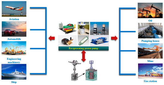
Figure 1.
Applications of the reciprocating piston pump.
The development of RPPs has been the focus of researchers’ attention, and the optimization of its structure and the improvement of the principle has very important economic benefits for the actual production. The conventional reciprocating piston pump distributing flow (RPPDF) system has drawbacks, such as loose structure, low volumetric efficiency (VE), and severe reflection lag at the high rotating speed [10,11]. The rotating-sleeve distributing flow (RSDF) system overcomes the disadvantages of the RPPDF system. However, when the plunger of the RSDF system reciprocates, the liquid pressure will be lower than the air separation pressure or the saturated vapor pressure. The vapor structures are formed within the oil appearing in the two coexisting states, also called cavitation [12,13,14]. Cavitation is an essential factor affecting the RSDF system’s VE and increases vibration and noise [15,16,17].
1.1. Literature Review
The hydraulic transmission system relies on hydraulic pumps to provide power. As a common power source, RPP uses the reciprocating movement of the plunger to periodically change the volume of the working chamber to transport fluid; now, it has become an indispensable part in many fields, such as automobiles and construction machinery [18,19]. The conventional RPP mostly uses one-way valves or solenoid valves for flow distribution [20,21,22]. The one-way valve has hysteresis when opening and closing; especially at high speed, the hysteresis of the one-way valve is more serious, which leads to lower VE of the pump. The solenoid valve solves the problem of hysteresis. However, new issues have emerged, such as increased costs, challenging to install and arrange, and the frequent opening and closing of the solenoid valve increases the noise of the RPP [23,24]. Increasingly sophisticated machinery puts forward higher requirements on the hydraulic system. Hydraulic pumps are developing towards high integration and increased agility. Under this new situation, it is indispensable to find a new RPPDF system.
For hydraulic systems, cavitation has always been a hot issue studied [25]. The appearance of cavitation will cause cavitation erosion and increase the noise of the system [26]. The traditional cavitation analysis methods have many limitations on engineering applications; at the beginning of this century, the computational fluid dynamics (CFDs) cavitation model developed rapidly, in which the most typical are the models proposed by Schnerr [27], Singhal [28], and Zwart [29], etc. In recent years, there has been an increasing amount of literature on cavitation. Xu et al. [30] proposed a new cavitation model combined with LES; this model was utilized to simulate the tip-leakage cavitating flow around a NACA0009 hydrofoil. Ram et al. [31] addressed the longstanding question by experimental study; that was, why inception of attached cavitation on curved surfaces or hydrofoils at incidence was relatively insensitive to the concentration of free-stream nuclei. Wu et al. [32] proposed a generalized definition of cavitation intensity for energy; the research derived an approximate formula to calculate the cavitation intensity and discussed its measure method. An et al. [33] studied the cavitation performance of the nuclear reaction coolant pump under the reverse pump mode; the research proposed a new method based on the average vapor volume fractions (VVFs) to estimate the cavitation. As can be seen, cavitation has been researched in various ways. For a specific hydraulic system, it is necessary to find a suitable cavitation model for the system.
It is well-acknowledged that a hydraulic pump’s performance determines the hydraulic system’s quality, and cavitation is an inevitable problem when the pump is working [34,35]. For the cavitation research of piston pumps, many studies have been done through simulation or experiments. Sun et al. [36] simulated the cavitation flow of the axial piston pump (APP) by the FLUENT software; the research put forward the two-way inclined type cylinder barrel kidney shape port, which could inhibit the cavitation of the plunger cavity. Yin et al. [37] developed a fully dynamic numerical model to understand the operational performance of seawater hydraulic APP under cavitation effects, and he built a test rig to validate the CFDs simulations. Chao et al. [38] presented an extensive analysis of the centrifugal impact on the cylinder cavitation of APPs; this paper used analytical and simulation methods to study the cylinder pressure and cavitation. Shi et al. [39] employed CFD to analyze the cavitation flow near a damping groove of a valve plate inside an APP; the research found that the cavitation can be effectively restrained by increasing the number of V-shaped grooves or the aspect ratio of the cross-section of U-shaped groove. However, many of these cavitation studies stay at the simulation stage. Some experimental studies also have a short comparison between simulation and experiment.
As a new RPPDF system, the RSDF system has not been fully developed. Xu et al. [40] established the kinematic characteristic of the RSDF system to research its state of motion. Zhang et al. [41] developed governing equations of the plunger and rotating sleeve; a CFD model of the RSDF system was established to simulate flow field and working pulsation. This research provides foundations for investigating flow field characteristics and structure optimization of the RSDF system. To reduce pressure pulsation, Zhang et al. [42] optimized the angle between valve port and chamber of the RSDF system; meanwhile, the research was the first time to discover the cavitation in the RSDF system. However, this research of the RSDF system mainly focuses on the kinematics and the flow field characteristics, and rare consideration is given to cavitation, which is a factor that seriously affects the performance of the RSDF system. Although the research [42] found the cavitation of the system, it did not establish a cavitation model that is suitable for the RSDF system. Moreover, this research is still at the theoretical stage and has not been confirmed by experiments.
1.2. Contributions of the Work
The conventional RPPDF systems have the disadvantages of the loose structure and low VE, as well as affected positively by the operating frequency. In this paper, a novel system is to be presented for bridging these drawbacks. This paper attempts to make several notable contributions and improvements to the current techniques, as shown in the following:
- A novel RPPDF system: This paper proposes a novel RSDF system that realizes the reciprocating motion of the plunger and single-track rotation of the rotating sleeve to achieve distribution functions. This structure has an excellent performance in a compact, sealing and VE.
- Optimized structure: In the process of processing and experiment of the RSDF system, it was found that the original structure had problems, such as the drive pin does not run smoothly along with the cam groove profile (CGP) and difficulty in oil supply and discharge. This paper improves the structure by increasing the diameter of the inlet and outlet ports; moreover, this research redesigns four-CGPs. Simulations and experiments have proven that the RSDF system can operate smoothly.
- Singhal cavitation model: This paper establishes the Singhal cavitation model specifically for the RSDF system and four CGPs. Using Singhal’s default values, the cavitation simulation analysis is implemented on four CGPs designed under standard conditions and different rotating speeds to find the most suitable CGP. Cavitation is evaluated from three aspects: VVF, cavitation ratio (CR), and VE. The stronger the cavitation, the greater the VVE and CR, and the smaller the VE. This paper is the first to study the RSDF system’s cavitation, which is of great significance to further research.
- Improved analytical methods: The research, for the first time, simultaneously uses an improved simulation model and experiment to analyze the RSDF system. The simulation model considers the gap between the rotating sleeve and the pump chamber, which uses hydraulic oil as the working medium to make the simulation more practical, rather than uses water as in previous simulations. The cavitation experiment is implemented on one CGP with the best cavitation characteristics in simulation. The experiments proved the feasibility of the theory of the RSDF system. Moreover, the existence of cavitation in the system is verified, and the variation law of cavitation in the simulation is correct.
1.3. Organization of the Paper
2. Fluid Model and Cavitation Model
2.1. Fluid Model
The RSDF system is a highly integrated system that combines the RPP with flow distribution; the structure is shown in Figure 2. The plunger is driven by the crank linkage mechanism to perform reciprocating linear motion when the system is working. Simultaneously, the rotating sleeve is rotated in one direction to realize the function of transmitting energy. The fluid model of the RSDF system is shown in Figure 3, and the characteristics of the RSDF system can be summarized as follows:
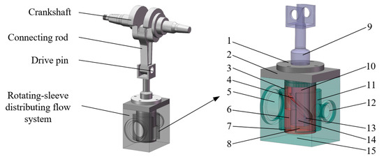
Figure 2.
Structure principle of the rotating-sleeve distributing flow (RSDF) system. (1) Guide sleeve; (2) Cover; (3) Loading chamber; (4) Inner cam groove; (5) Oil inlet; (6) Valve port; (7) Damping groove; (8) Pump chamber; (9) Plunger; (10) Rotating sleeve; (11) Collecting chamber; (12) Oil outlet; (13) Drive pin; (14) Compression spring; (15) Pump body.
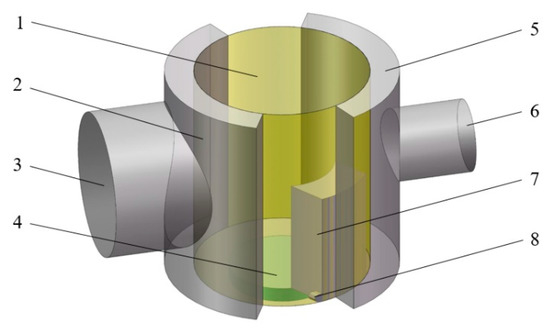
Figure 3.
Fluid model of RSDF system. (1) Rotating sleeve gap; (2) Loading chamber; (3) Oil inlet; (4) Pump body; (5) Collecting chamber; (6) Oil outlet; (7) Valve port; (8) Damping groove.
- A hole is machined at the bottom of the plunger, the compression spring and drive pin are put into it, and the inner surface of the rotating sleeve is designed with a cam groove. Under the force of the compression spring, the drive pin is compressed in the cam groove. When the plunger reciprocates, the drive pin at the bottom of the plunger moves along the CGP to drive the rotating sleeve to rotate in one direction;
- There is a valve port on the rotating sleeve, which rotates in one direction following the rotating sleeve. When the plunger moves up, the valve port is connected to the loading chamber, and the oil flows into the pump chamber through the valve port; when the plunger moves down, the valve port is connected with the collecting chamber, and the oil in the pump chamber is discharged through the valve port;
- To ensure that the rotating sleeve can rotate in one direction, the cam groove’s depth is designed. The depth step is designed at the top and bottom dead center to enable the drive pin to move along the established CGP.
2.2. Design of the CGP
On one hand, when the system is working, the crank linkage mechanism drives the plunger to reciprocate. On the other hand, the rotating sleeve performs continuous single-track rotation. The relationship between the axial displacement of the plunger and the crank angle is:
where z is the axial displacement of the plunger; φ = ωt, φ is the crank angle; t is time; ω = 2πn/60, ω is the angular velocity of the crankshaft; n is the rotating speed of the crankshaft; λ = r0/l0, λ is the crank link ratio; r0 is the radius of the crankshaft; l0 is the length of the connecting rod.
The radial depth of the cam groove is designed to ensure the rotating sleeve’s continuous single-track rotation with the plunger’s reciprocating motion. The radial equation expressed by Equation (2) controls the change in-depth of the cam groove.
where r is the radial depth of the cam groove; d is the diameter of the plunger; Δh = h2 − h1 is the depth change of the cam groove; h1 is the minimum depth of the cam groove; h2 is the maximum depth of the cam groove; θ is the rotating sleeve angle.
This paper designs four CGPs, and the relationship between the rotating sleeve angle of the anti-sinusoidal CGP and the crank angle is:
The relationship between the rotating sleeve angle of the linear CGP and the crank angle is:
The relationship between the rotating sleeve angle of the tangent CGP and the crank angle is:
The relationship between the rotating sleeve angle of the spline CGP and the crank angle is:
where z is the z in Equation (1).
Expand the four CGPs along the circumference, and the shape is shown in Figure 4, and the relationship between the angular velocity (ω1) of the four CGPs rotating sleeve and the crank angle is shown in Figure 5. It can be seen from Figure 4 and Figure 5 that various CGPs show an obvious symmetry. When the plunger moves to the top and bottom dead center, the spline profile has the longest transition time, which is not conducive to converting the oil in and out of the system. In turn, the transition time of the anti-sinusoidal profile, the tangent profile, and the linear profile decrease. However, the angular velocity of the spline profile and anti-sinusoidal profile is relatively gentle in the transition phase, which reduces the impact of the conversion process, and the linear profile has the greatest impact on the conversion process. The four CGPs redesigned have their own advantages and disadvantages, and they can all meet the kinematic characteristics of the RSDF system. From the perspective of cavitation, we will continue to analyze these four CGPs.
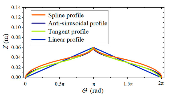
Figure 4.
Cam groove profiles (CGPs) circumferential expanded view.

Figure 5.
Angular velocity of the rotating sleeve.
2.3. Cavitation Model
The working medium of the RSDF system is hydraulic oil, and the cavitation simulation analysis will be affected by the vapor and surface tension in the oil. Meanwhile, the flow field is a turbulent flow, and turbulent kinetic energy affects cavitation. The Singhal cavitation model considers the influence of turbulent flow, vapor motion, liquid surface tension, etc., on the vapor phase; it is suitable for accurate calculation of liquid cavitation, so the Singhal cavitation model is selected to simulate the cavitation of this system [43,44,45]. Ignoring the influence of second-order terms, liquid viscosity, and surface tension on the growth of the bubble, the fundamental equation of the bubble dynamics can be simplified to:
where R is the surface radius of the bubble; pb is the surface pressure of the bubble; pc is the local far-field pressure.
The final form of evaporation rate and condensation rate of vapor–liquid mass transfer is:
where ρv is the vapor phase density; ρl is the liquid phase density; fg is the permanent vapor mass fraction; fv is the steam mass fraction, p is liquid pressure, pv is saturated vapor pressure; σ is the liquid surface tension coefficient; recommended empirical coefficient value Ce = 0.02, Cc = 0.01.
User-defined function (UDF) of Fluent software (Fluent 16.0, Qingdao, China) is used in simulation to ensure fluid model motion. The RNG k-ε turbulence model and SIMPLE algorithm are used for an iterative calculation to further discuss the effect of CGP on cavitation [46,47]. Table 1 shows the simulation parameters of the RSDF system.

Table 1.
Simulation parameters.
2.4. Mesh Independence Verification
The fluid model of the RSDF system is divided by the structured mesh using the ICEM CFD meshing tool to ensure high mesh quality, and the boundary layer mesh is encrypted. The fluid model’s mesh is shown in Figure 6.

Figure 6.
Fluid mesh model.
The mesh density of the fluid model has a significant influence on the calculation results. Only when the mesh number has little effect on the calculation results, the results of numerical simulation are meaningful, so it is necessary to perform mesh independence verification [48,49].
By setting different mesh sizes, this paper obtains five sets of mesh models of the fluid model. The number of each part and the total mesh number are shown in Table 2. VE is an important performance indicator when studying cavitation problems. The relationship between VE (ηv) and mesh grouping is shown in Figure 7. The calculation results show that the VE increases that accompany the increasing number of mesh, but when the total number of mesh exceeds 337,000, the simulation results are basically unaffected by the number of mesh, so mesh 3 is preferred as a mesh model for cavitation simulation of the RSDF system.

Table 2.
Number of mesh in each part of the fluid model.

Figure 7.
Comparison results of volumetric efficiency (VE) of different mesh models.
Meanwhile, the quality of the mesh also directly affects the accuracy of the simulation results. The mesh quality can be checked according to various standards, and the structured hexahedral mesh is usually evaluated by the isometric slope ES. It is defined as:
where θmax is the maximum angle of the geometry in the fluid mesh model; θmin is the minimum angle of the geometry in the fluid mesh model; θe is the degree of inner angles of the isometric polygon.
An ES value closing to 1 represents a higher mesh quality. The ES distribution of mesh 3, which has been selected above, is shown in Figure 8. It can be seen that the ES values of most of the meshes are above 0.8, indicating that the overall quality of the mesh of the fluid model is high and meets the calculation requirements. Finally, mesh 3 is determined as the fluid mesh model for the cavitation simulation.
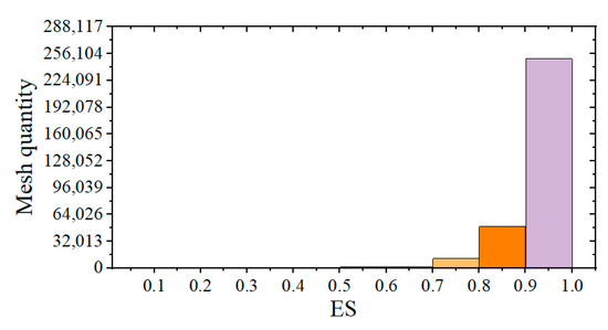
Figure 8.
Mesh 3 ES distribution.
3. The Relationship between CGP and Cavitation
3.1. Analysis of Cavitation under Standard Conditions
The cavitation of the RSDF system is generated in the initial stage of oil intake. The cavitation vapor is mainly concentrated in the valve port and the pump chamber. Simulations are carried out under standard conditions of 500 r/min, inlet pressure 0.1 MPa and load pressure 10 MPa. In the simulation, select “pressure-based” in Solver, set the boundary conditions to pressure-inlet and pressure-outlet, set the time step to 0.0001, and set the Convergence Criterion to none. In addition, the turbulence model is RNG k-ε, and SIMPLE is selected as the algorithm. Figure 9 shows the distribution of cavitation vapor in the valve port and pump chamber at a certain moment. It can be seen from Figure 9 that the valve port and the pump chamber have different degrees of cavitation; the cavitation of the pump chamber is stronger.

Figure 9.
The simulated vapor distribution. (a) Valve port vapor volume fractions (VVF); (b) pump chamber VVF.
However, the VVFs in different areas of the valve port and the pump chamber is not the same, so a detailed analysis of the overall cavitation cannot be performed. Therefore, the average VVF was monitored during the simulation to reflect cavitation. The valve port average VVF (αv) and pump-chamber average VVF (αp) of different CGPs are shown in Figure 10.

Figure 10.
Average vapor distribution of different CGPs. (a) Valve port average VVF; (b) pump chamber average VVF.
It can be seen from Figure 10 that the spline profile displays the strongest cavitation at the valve port, the duration of the cavitation occupies 19.33% of the single operating cycle, and the VVF reaches 28.18% when the working time is 0.015 s. The anti-sinusoidal profile and the tangent profile declined gradually. In contrast, the linear profile shows that the maximum VVF is only 8%, and the process accounts for 12.33% with the weakest cavitation. The change of VVF of each CGP in the pump chamber is consistent with that in the valve port, but the cavitation is higher significantly. The spline profile has a maximum VVF of 46.15%, and the cavitation time accounts for 23% of a single operating cycle. In comparison, the maximum VVF of the linear profile with the smallest cavitation is also 27.16%, and the time accounts for 16%. Overall, the linear profile has the lowest cavitation intensity and the shortest duration under standard conditions, which is better than the other three profiles.
3.2. Analysis of Cavitation at Different Rotating Speeds
In the actual working process of the RSDF system, the working speed will affect the cavitation characteristics of the system. This paper sets the inlet pressure and the load pressure to 0.1 MPa and 10 MPa, respectively, for the four CGPs designed above. It conducts simulation at different rotating speeds to determine the optimal working speed of the distributing flow system. Meanwhile, it provides a theoretical basis for experimental research. The mathematical quantities representing the cavitation are mainly the maximum VVF, the cavitation ratio (CR), and the VE.
3.2.1. Maximum VVF
The maximum VVF is expressed as:
where Vgmax is the maximum instantaneous vapor volume; V is the total volume of the system.
The maximum VVF increases following the increase of the rotating speed (n), as shown in Figure 11. The linear CGP at the valve port has the lowest growth rate and is always maintained below 10%, the spline profile has the most massive increase, and the maximum VVF can reach more than 30%. The cavitation in the pump chamber is more prominent. The maximum VVF of these CGPs in the high rotating speed is above 40%. The spline profile and the anti-sinusoidal profile are more than 50% having a large instantaneous cavitation intensity. In general, the linear profile’s cavitation intensity is the weakest among the above CGPs.
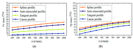
Figure 11.
Relationship between maximum VVF and rotating speed. (a) Valve port maximum VVF; (b) pump chamber maximum VVF.
3.2.2. CR
The maximum VVF can only indicate the intensity of cavitation. To judge the degree of cavitation of the distribution flow system, it is also necessary to consider the cavitation duration, so the CR is introduced to indicate the duration of cavitation in a cycle.
where tc is the cavitation duration in a single work cycle; T is the work cycle.
The larger CR indicates that the cavitation exists for a long time, having a significant influence on the RSDF system’s working process. The variation of the valve port CR (τv) and pump chamber CR (τp) with the rotating speed is shown in Figure 12. It can be seen that the corresponding CR of these CGPs increases that accompany the increase of the rotating speed in the valve port and the pump chamber, and the middle range has a faster growth. The linear profile has the smallest CR among different CGPs; the spline profile displays the largest CR. After the operating speed is more significant than 800 r/min, the tangent profile’s CR, the anti-sinusoidal profile, and the spline profile reach more than 20% at the valve port signals. These three CGPs are more than 25% in the pump chamber. Overall, the linear profile’s cavitation is the smallest, having apparent advantages.

Figure 12.
Relationship between cavitation ratio (CR) and rotating speed. (a) Valve port CR; (b) pump chamber CR.
3.2.3. VE
The formula for the VE of the distribution flow system is:
where Qc is the actual output flow; Qt is the theoretical output flow.
The generation of cavitation will affect the VE of the RSDF system. Compare the VE of different CGPs, as shown in Figure 13. The distribution flow system’s VE increases first. It then decreases following the increase of the rotating speed. When the rotating speed is lower than 500 r/min, the VE increases gradually, and the VE begins to decrease when the speed is higher than 500 r/min. The linear CGP, the maximum VE of 92.13%, has the highest VE. Then the VE of the tangent profile, the anti-sinusoidal profile and the spline profile reduced sequentially. The spline CGP in the simulation has the lowest VE. Still, the increasing trend is the most obvious. The linear profile’s cavitation characteristics in these CGPs are optimal.

Figure 13.
Relationship between VE and rotating speed.
In this paper, the linear CGP with the best cavitation is selected for experimental research. The cavitation of the RSDF system is continuously explored.
4. Experimental Study on Cavitation
The experiment is carried out on the YST380W hydraulic comprehensive experiment bench (HCEB), as shown in Figure 14. The HCBE is mainly composed of the drive motor, hydraulic oil tank console, and console. All the operations of the experiment are completed through the operation area of the console. There is also a digital display area on the console to display the current pressure, rotating speed, and other states. The HCBE can monitor the VE, and the monitored results are displayed on the computer display area. After the console gives a rotation command, the drive motor starts to drive the RSDF system to rotate, and after giving the pressure command, the hydraulic oil tank console will provide the pressure according to the command. The RSDF system’s overall structure is designed according to the HCEB, as shown in Figure 15.

Figure 14.
Hydraulic comprehensive experiment bench (HCEB). (a) Workbench; (b) Console.
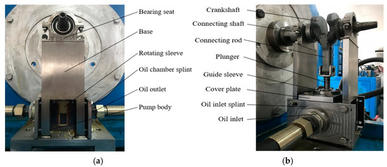
Figure 15.
Structure of the RSDF system. (a) Front view; (b) Left view.
The HCEB has the function of monitoring the pump’s VE, so the VE monitoring experiment uses a pump body of high-strength nylon material. During the experiment, the inlet pressure and outlet pressure are set to 0.1 Mpa and 10 Mpa, respectively, to monitor the VE at different speeds. The comparison of the VE of the experiment and simulation is shown in Figure 16.

Figure 16.
VE at different rotating speeds.
The system’s VE monitored by the HCEB is the same as that of the simulated VE. Still, the value under the experiment is lower than the simulation. The reasons for the analysis are that: on one hand, there is a specific error in the actual processing resulting in increased leakage of oil. On the other hand, the shearing effect between the rotating sleeve and the pump body increases cavitation. The maximum VE monitored at the rotating speed of 500 r/min is 90.23%, and the error is 2%.
It can be seen that the optimal working speed of the RSDF system is around 500r/min, which is consistent with the simulation results.
5. Conclusions
This paper has presented a novel RSDF system, optimized structure, and the cavitation analysis method of the RSDF system. The four CGPs were applied to analyze the cavitation from the three aspects of maximum vapor volume fraction, cavitation ratio and volumetric efficiency. The results show that the vapor volume fraction analysis of the four CGPs shows that the spline profile displays the strongest cavitation among different profiles. The anti-sinusoidal profile and the tangent profile declined gradually, while the linear profile’s cavitation is the weakest. The rule will maintain unchanged if there is a different rotating speed. The four CGPs’ cavitation ratio increases following the rotating speed. Simultaneously, the spline profile has the highest cavitation ratio, the cavitation exists for a long time, and the linear profile is the lowest. The volumetric efficiency of the four CGPs increases first. It then decreases that accompanies the increase of the rotating speed, and the maximum value is obtained at the speed of 500 r/min. The linear profile has the highest volumetric efficiency. In turn, the volumetric efficiencies of the tangent profile, the anti-sinusoidal profile, and the spline profile decrease at the same speed. The experiments verify the cavitation phenomenon. The experiment observes cavitation bubbles in the system at the initial stage of oil intake, and the higher the rotating speed, the more bubbles are observed. The volumetric efficiency detected by the hydraulic experiment bench is the same as the simulation result, and the calculation error is about 2%.
The RSDF system will replace the RPPDF system as a novel “heart” of the hydraulic system. It can be applied to various fields, such as automotive, ships, aviation, engineering machinery. Future research will analyze the practicability of the RSDF system for specific application machinery. As a new type of distribution flow system, the RSDF system has its advantages and significance. It can be predicted that with the continuous research and development of the RSDF system, this system will become an innovation that promotes the reform of the RPPDF system.
Author Contributions
Conceptualization, S.D. and H.Z.; methodology, S.D. and J.H.; software, S.D. and X.J.; validation, J.H. and H.Z.; formal analysis, Q.Z. and T.Z.; investigation, X.X. and X.J.; resources, H.Z.; data curation, J.H. and X.X.; writing—original draft preparation, S.D. and H.Z.; writing—review and editing, S.D. and J.H.; supervision, Q.Z. and Tiezhu.Zhang; project administration, H.Z. and Q.Z.; funding acquisition, H.Z. and Q.Z. All authors have read and agreed to the published version of the manuscript.
Funding
This research is partly funded by the National Natural Science Foundation of China (Grant No. 51705268, 51575286).
Institutional Review Board Statement
Not applicable.
Informed Consent Statement
Not applicable.
Data Availability Statement
Data is contained within the article.
Conflicts of Interest
The authors declare no conflict of interest.
Nomenclature
| z | Axial displacement of the plunger |
| φ | Crank angle |
| ω | Angular velocity of the crankshaft |
| λ | Crank link ratio |
| r | Radial depth of cam groove |
| d | Diameter of plunger |
| Δh | Depth change of cam groove |
| θ | Rotating sleeve angle |
| R | Surface radius of the bubble |
| pb | Surface pressure of the bubble |
| pc | Local far-field pressure |
| ρv | Vapor phase density |
| ρl | Liquid phase density |
| fg | Permanent vapor mass fraction |
| fv | Steam mass fraction |
| p | Liquid pressure |
| pv | Saturated vapor pressure |
| σ | Liquid surface tension coefficient |
| α | vapor volume fraction |
| Vgmax | Maximum instantaneous vapor volume |
| V | Total volume of the RSDF system |
| τ | Cavitation ratio |
| tc | Cavitation duration in a work cycle |
| T | Work cycle |
| ηv | Volumetric efficiency |
| Qc | Actual output flow |
| Qt | Theoretical output flow |
Nomenclature
| APP | Axial piston pump |
| CFD | Computational fluid dynamic |
| CGP | Cam groove profile |
| VVF | Vapor volume fraction |
| CR | Cavitation ratio |
| HCEB | Hydraulic comprehensive experiment bench |
| RPP | Reciprocating piston pump |
| RPPDF | Reciprocating piston pump distributing flow |
| RSDF | Rotating-sleeve distributing flow |
| UDF | User-defined function |
| VE | Volumetric efficiency |
References
- He, X.; Xiao, G.; Hu, B.; Tan, L.; Tang, H.; He, S.; He, Z. The applications of energy regeneration and conversion technologies based on hydraulic transmission systems: A review. Energy Convers. Manag. 2020, 205, 112413. [Google Scholar] [CrossRef]
- Zhao, Q.; Zhang, H.; Xin, Y. Research on Control Strategy of Hydraulic Regenerative Braking of Electrohydraulic Hybrid Electric Vehicles. Math. Probl. Eng. 2021, 2021. [Google Scholar] [CrossRef]
- Uchiyama, T.; Honda, S.; Okayama, T.; Degawa, T. A Feasibility Study of Power Generation from Sewage Using a Hollowed Pico-Hydraulic Turbine. Engineering 2016, 2, 510–517. [Google Scholar] [CrossRef]
- Munih, J.; Hocevar, M.; Petric, K.; Dular, M. Development of CFD-based procedure for 3d gear pump analysis. Eng. Appl. Comput. Fluid Mech. 2020, 14, 1023–1034. [Google Scholar] [CrossRef]
- Zhu, D.; Fu, Y.; Han, X.; Li, Z. Design and experimental verification on characteristics of electro-hydraulic pump. Mech. Syst. Signal Process. 2020, 144, 106771. [Google Scholar] [CrossRef]
- Zuo, Z.; Liu, S. Flow-Induced Instabilities in Pump-Turbines in China. Engineering 2017, 3, 504–511. [Google Scholar] [CrossRef]
- Zhou, J.; Jing, C.; Liu, J. On the steady posture of conical spindle distribution used in ball piston pump. Proceedings of the Institution of Mechanical Engineers, Part J. J. Eng. Tribol. 2019, 234, 490–499. [Google Scholar]
- Ma, Y.; Chen, Y.; Zhang, S. Numerical study on void fraction wave of reciprocating multiphase pumps with high gas rates based on real gas models. Eng. Appl. Comput. Fluid Mech. 2020, 14, 607–621. [Google Scholar] [CrossRef]
- Wang, J.; Huang, Z. The Recent Technological Development of Intelligent Mining in China. Engineering 2017, 3, 439–444. [Google Scholar] [CrossRef]
- Ma, Y.; Ni, Y.; Zhang, H.; Zhou, S.; Deng, H. Influence of valve’s lag characteristic on pressure pulsation and performance of reciprocating multiphase pump. J. Pet. Sci. Eng. 2018, 164, 584–594. [Google Scholar] [CrossRef]
- Ma, Y.; Luo, H.; Gao, T.; Zhang, Z. Transient flow study of a novel three-cylinder double-acting reciprocating multiphase pump. J. Fluids Eng. 2017, 139. [Google Scholar] [CrossRef]
- Liu, X.; Wu, Z.; Li, B.; Zhao, J.; He, J.; Li, W.; Zhang, C.; Xie, F. Influence of inlet pressure on cavitation characteristics in regulating valve. Eng. Appl. Comput. Fluid Mech. 2020, 14, 299–310. [Google Scholar] [CrossRef]
- Zhao, X.; Liu, T.; Huang, B.; Wang, G. Combined experimental and numerical analysis of cavitating flow characteristics in an axial flow waterjet pump. Ocean Eng. 2020, 209, 107450. [Google Scholar] [CrossRef]
- Zhou, J.; Wei, C.; Yuan, S. An analytical model of gas content in fluids considering the distribution of bubble radius. Lubrication Sci. 2017, 29, 227–239. [Google Scholar] [CrossRef]
- Chao, Q.; Zhang, J.; Xu, B.; Huang, H.; Zhai, J. Effects of inclined cylinder ports on gaseous cavitation of high-speed electro-hydrostatic actuator pumps: A numerical study. Eng. Appl. Comput. Fluid Mech. 2019, 13, 245–253. [Google Scholar] [CrossRef]
- Xu, S.; Wang, J.; Cheng, H.; Ji, B.; Long, X. Experimental study of the cavitation noise and vibration induced by the choked flow in a venturi reactor. Ultrason. Sonochemistry 2020, 67, 105183. [Google Scholar] [CrossRef] [PubMed]
- Ye, S.; Zhang, J.; Xu, B. Noise reduction of an axial piston pump by valve plate optimization. Chin. J. Mech. Eng. 2018, 31, 57. [Google Scholar] [CrossRef]
- Yu, D.; Zhang, H. Fault diagnosis method for submersible reciprocating pumping unit based on deep belief network. IEEE Access 2020, 8, 109940–109948. [Google Scholar] [CrossRef]
- Sun, H.; Yang, L.; Jing, J.; Luo, Y. Control strategy of hydraulic/electric synergy system in heavy hybrid vehicles. Energy Convers. Manag. 2011, 52, 668–674. [Google Scholar]
- Ma, Y.; Luo, H.; Zhang, Z.; Zhou, S.; Deng, H. Numerical modeling of dynamic characterics for combined valves in multiphase pump. Eng. Appl. Comput. Fluid Mech. 2017, 11, 328–339. [Google Scholar] [CrossRef]
- Deng, H.; Liu, Y.; Li, P.; Zhang, S. Hybrid model for discharge flow rate prediction of reciprocating multiphase pumps. Adv. Eng. Softw. 2018, 124, 53–65. [Google Scholar] [CrossRef]
- Romer, M.C.; Brown, M.; Ainsworth, N.; Rundberg, O.; Bolt, D.J.; Bolt, T.; Tolman, R.C. Field trial of a novel self-reciprocating hydraulic pump for deliquification. Spe Prod. Oper. 2017, 32, 527–538. [Google Scholar] [CrossRef]
- Wang, L.; Li, G.; Xu, C.; Xi, X.; Wu, X.; Sun, S. Effect of characteristic parameters on the magnetic properties of solenoid valve for high-pressure common rail diesel engine. Energy Convers. Manag. 2016, 127, 656–666. [Google Scholar] [CrossRef]
- Zhu, G.; Dong, S. Analysis on the performance improvement of reciprocating pump with variable stiffness valve using CFD. J. Appl. Fluid Mech. 2020, 13, 387–400. [Google Scholar] [CrossRef]
- Zhou, J.; Vacca, A.; Casoli, P. A novel approach for predicting the operation of external gear pumps under cavitating conditions. Simul. Model. Pract. Theory 2014, 45, 35–49. [Google Scholar] [CrossRef]
- Bilus, I.; Hocevar, M.; Dular, M.; Lesnik, L. Numerical prediction of various cavitation erosion mechanisms. J. Fluids Eng. 2020, 142, 041402. [Google Scholar] [CrossRef]
- Schnerr, G.H.; Sauer, J. Physical and numerical modeling of unsteady cavitation dynamics. In Proceedings of the 4th International Conference on Multiphase Flow, New Orleans, LA, USA, 27 May 2001. [Google Scholar]
- Singhal, A.K.; Athavale, M.M.; Li, H.; Jiang, Y. Mathematical basis and validation of the full cavitation model. J. Fluids Eng. 2002, 124, 617–624. [Google Scholar] [CrossRef]
- Zwart, P.J.; Gerber, A.G.; Belamri, T. A Two-phase flow model for predicting cavitation dynamics. In Proceedings of the 5th International Conference on Multiphase Flow, Yokohama, Japan, 30 May 2004. [Google Scholar]
- Xu, M.; Cheng, H.; Ji, B.; Peng, X. LES of tip-leakage cavitating flow with special emphasis on different tip clearance sizes by a new Euler-Lagrangian cavitation model. Ocean Eng. 2020, 213, 107661. [Google Scholar] [CrossRef]
- Ram, O.; Agarwal, K.; Katz, J. On the mechanisms that sustain the inception of attached cavitation. J. Fluid Mech. 2020, 901, R4. [Google Scholar] [CrossRef]
- Wu, P.; Bai, L.; Lin, W. On the definition of cavitation intensity. Ultrason. Sonochemistry 2020, 67, 105141. [Google Scholar] [CrossRef]
- An, C.; Zhu, R.; Long, Y.; Wang, X.; Lu, Y.; Chen, Y. The cavitation performance analysis of the RCP under LBLOCA at inlet. Ann. Nucl. Energy 2020, 148, 107605. [Google Scholar] [CrossRef]
- Chao, Q.; Tao, J.; Wei, X.; Liu, C. Identification of cavitation intensity for high-speed aviation hydraulic pumps using 2D convolutional neural networks with an input of RGB-based vibration data. Meas. Sci. Technol. 2020, 31, 105102. [Google Scholar] [CrossRef]
- Shen, X.; Zhang, D.; Xu, B.; Jin, Y.; Shi, W.; Van Esch, B.P.M. Experimental investigation of the transient patterns and pressure evolution of tip leakage vortex and induced-vortices cavitation in an axial flow pump. J. Fluids Eng. 2020, 142, 101206. [Google Scholar]
- Sun, Z.; Xiao, S.; Xu, M.; Wei, W. Optimization of the structure of water axial piston pump and cavitation of plunger cavity based on the Kriging model. J. Vibroengineering 2016, 18, 2460–2474. [Google Scholar]
- Yin, F.; Nie, S.; Xiao, S.; Hou, W. Numerical and experimental study of cavitation performance in sea water hydraulic axial piston pump. Proceedings of the Institution of Mechanical Engineers Part I. J. Syst. Control Eng. 2016, 230, 716–735. [Google Scholar]
- Chao, Q.; Zhang, J.; Xu, B.; Huang, H.; Zhai, J. Centrifugal effects on cavitation in the cylinder chambers for high-speed axial piston pumps. Meccanica 2019, 54, 815–829. [Google Scholar] [CrossRef]
- Shi, Y.; Lin, T.; Meng, G.; Huang, J. A study on the suppression of cavitation flow inside an axial piston pump. In Proceedings of the 2016 Prognostics and System Health Management Conference (PHM-Chengdu), Chengdu, China, 19 October 2016. [Google Scholar]
- Xu, W.; Zhang, H.; Shu, P.; Gao, L. Kinematics research of rotating-sleeve distributing-flow system for reciprocating plunger pump. In Proceedings of the 5th International Conference on Advanced Design and Manufacturing Engineering, Shenzhen, China, 19 September 2015. [Google Scholar]
- Zhang, Y.; Zhang, H.; Yang, J. Research on distribution of flow field and simulation of working pulsation based on rotating-sleeve distributing-flow system. Model. Simul. Eng. 2017, 2017, 1015494. [Google Scholar] [CrossRef]
- Zhang, Y.; Zhang, H.; Zhao, Q.; Jiang, X.; Cheng, Q. Research of working pulsation in closed angle based on rotating-sleeve distributing-flow system. In Proceedings of the International Conference on Green Energy and Sustainable Development (GESD), Chongqing, China, 27 May 2017. [Google Scholar]
- Zhai, Z.; Chen, T.; Li, H. Evaluation of mass transport cavitation models for unsteady cavitating flows. Mod. Phys. Lett. B 2020, 34, 2050020. [Google Scholar] [CrossRef]
- Du, T.; Wang, Y.; Liao, L.; Huang, C. A numerical model for the evolution of internal structure of cavitation cloud. Phys. Fluids 2016, 28, 077103. [Google Scholar] [CrossRef]
- Djahida, B.; Omar, I. Numerical simulation of the cavitating flow around marine co-rotating tandem propellers. Brodogradnja 2019, 70, 43–57. [Google Scholar] [CrossRef]
- Wang, X.; Zhao, H. A High-Efficiency Two-Stroke Engine Concept: The Boosted Uniflow Scavenged Direct-Injection Gasoline (BUSDIG) Engine with Air Hybrid Operation. Engineering 2019, 5, 351–594. [Google Scholar] [CrossRef]
- Gao, X.; Zhang, H.; Liu, J.; Sun, B.; Tian, Y. Numerical investigation of flow in a vertical pipe inlet/outlet with a horizontal anti-vortex plate: Effect of diversion orifices height and divergence angle. Eng. Appl. Comput. Fluid Mech. 2018, 12, 182–194. [Google Scholar] [CrossRef]
- Cao, W.; Mao, J. Study of the affinity law of energy and cavitation characteristics in emergency drainage pumps at different rotating speeds. Processes 2019, 7, 932. [Google Scholar] [CrossRef]
- Quan, L.; Gao, H.; Guo, C.; Che, S. Assessment of the dynamics flow field of port plate pair of an axial piston pump. Processes 2020, 8, 86. [Google Scholar] [CrossRef]
Publisher’s Note: MDPI stays neutral with regard to jurisdictional claims in published maps and institutional affiliations. |
© 2021 by the authors. Licensee MDPI, Basel, Switzerland. This article is an open access article distributed under the terms and conditions of the Creative Commons Attribution (CC BY) license (https://creativecommons.org/licenses/by/4.0/).