
Multiple-Vector Model Predictive Control with Fuzzy Logic for PMSM Electric Drive Systems


Abstract
1. Introduction
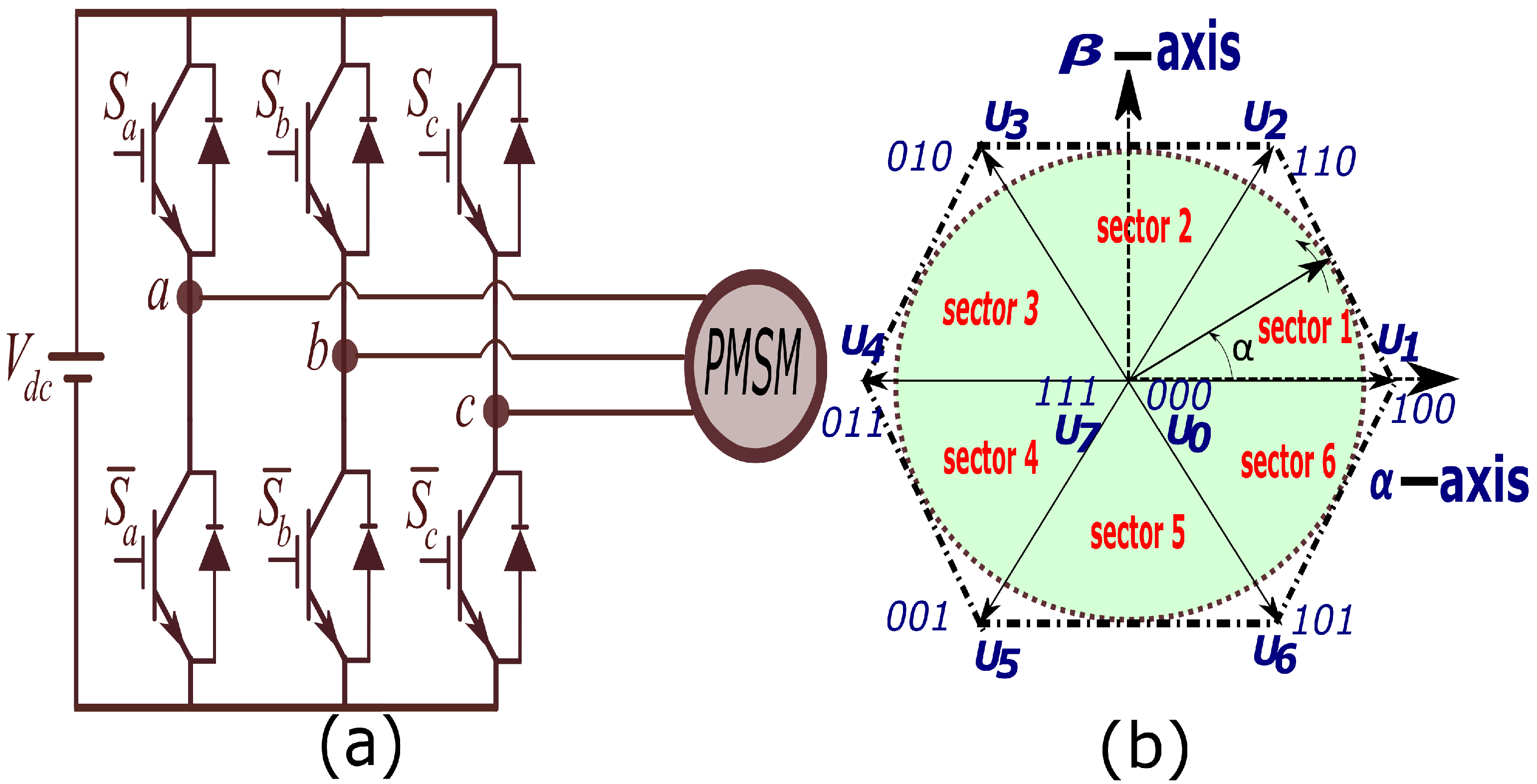
2. Drive Model
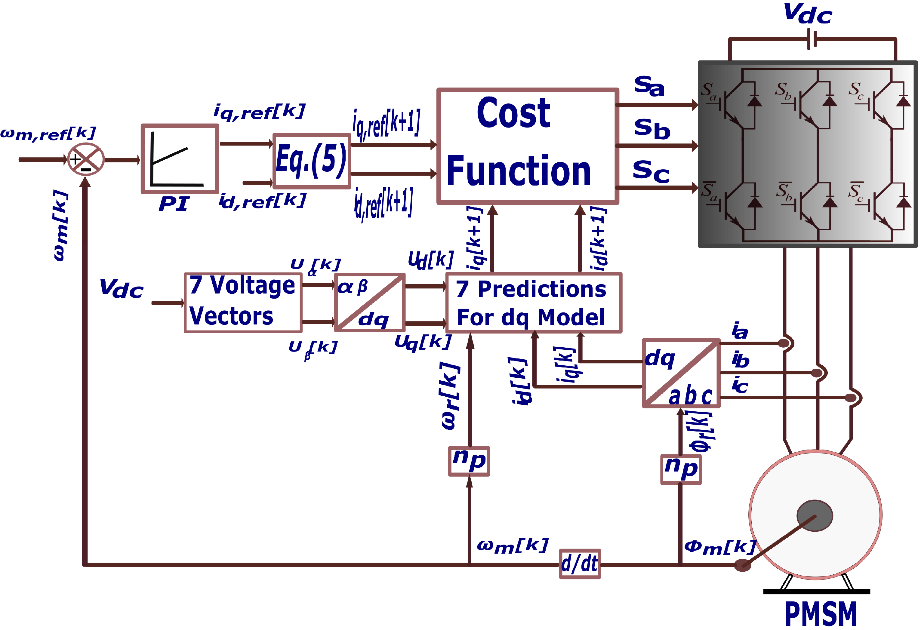
3. Traditional Finite-Control-Set Model Predictive Control (FCS-MPC)
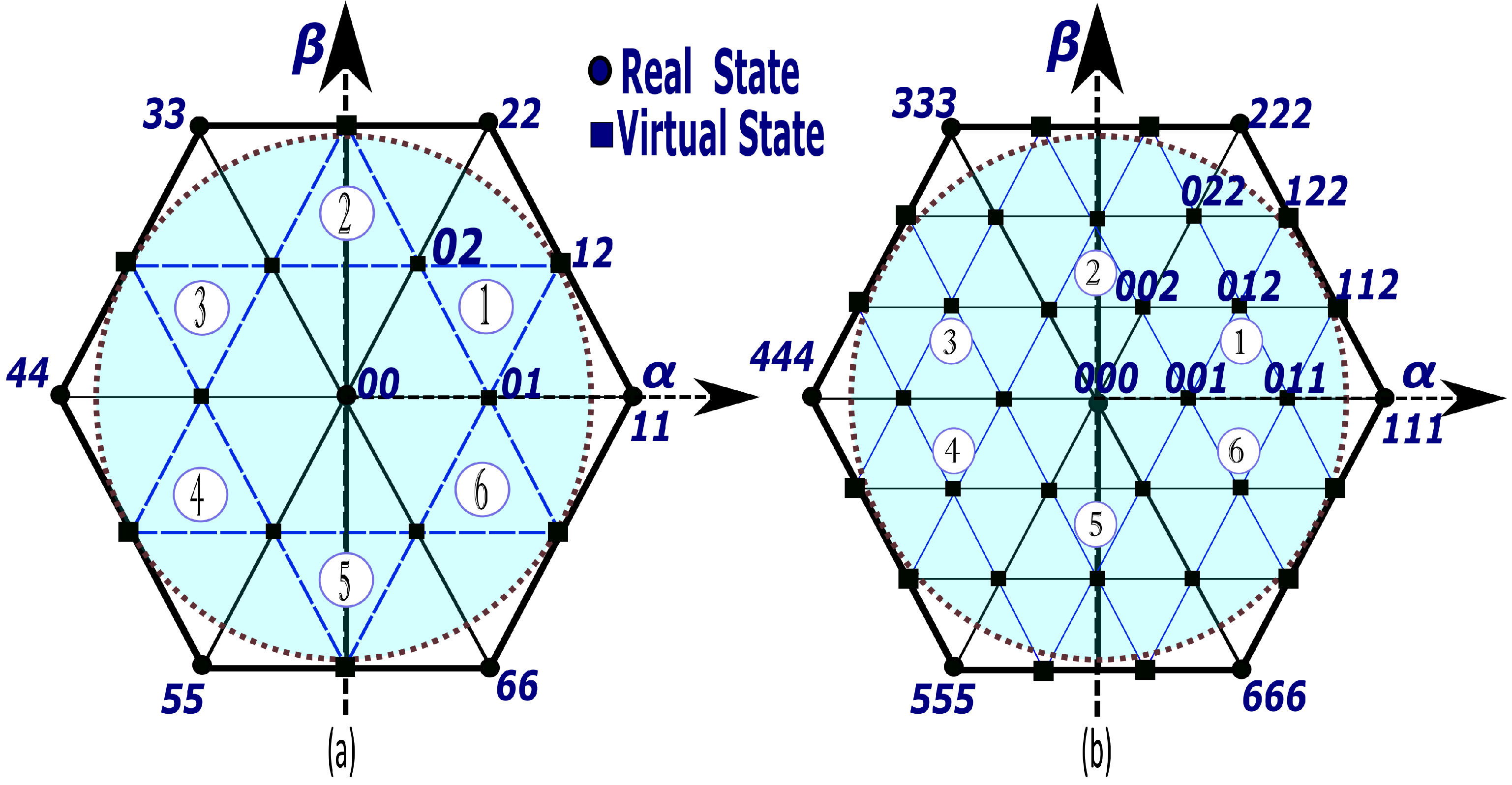
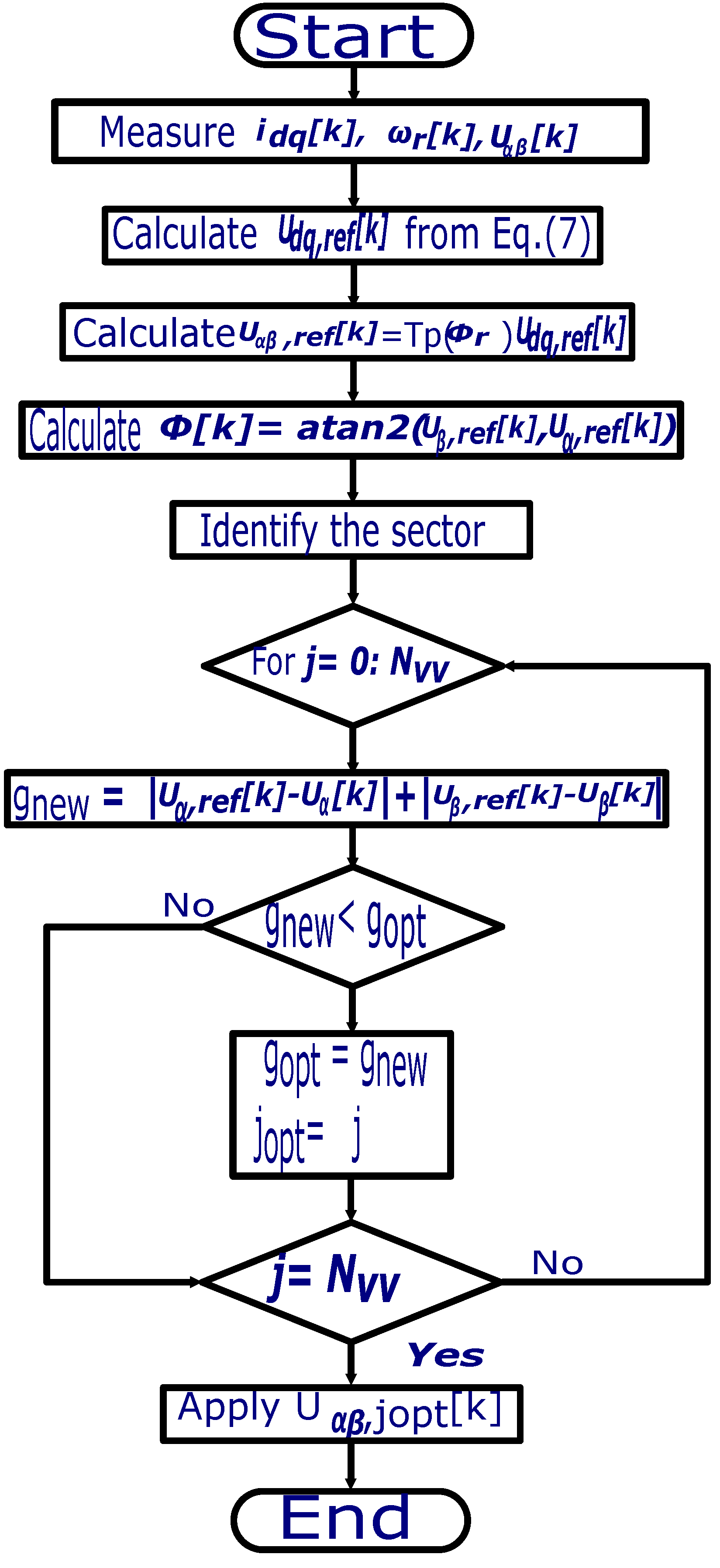
4. Proposed Multiple-Vector FCS-MPC
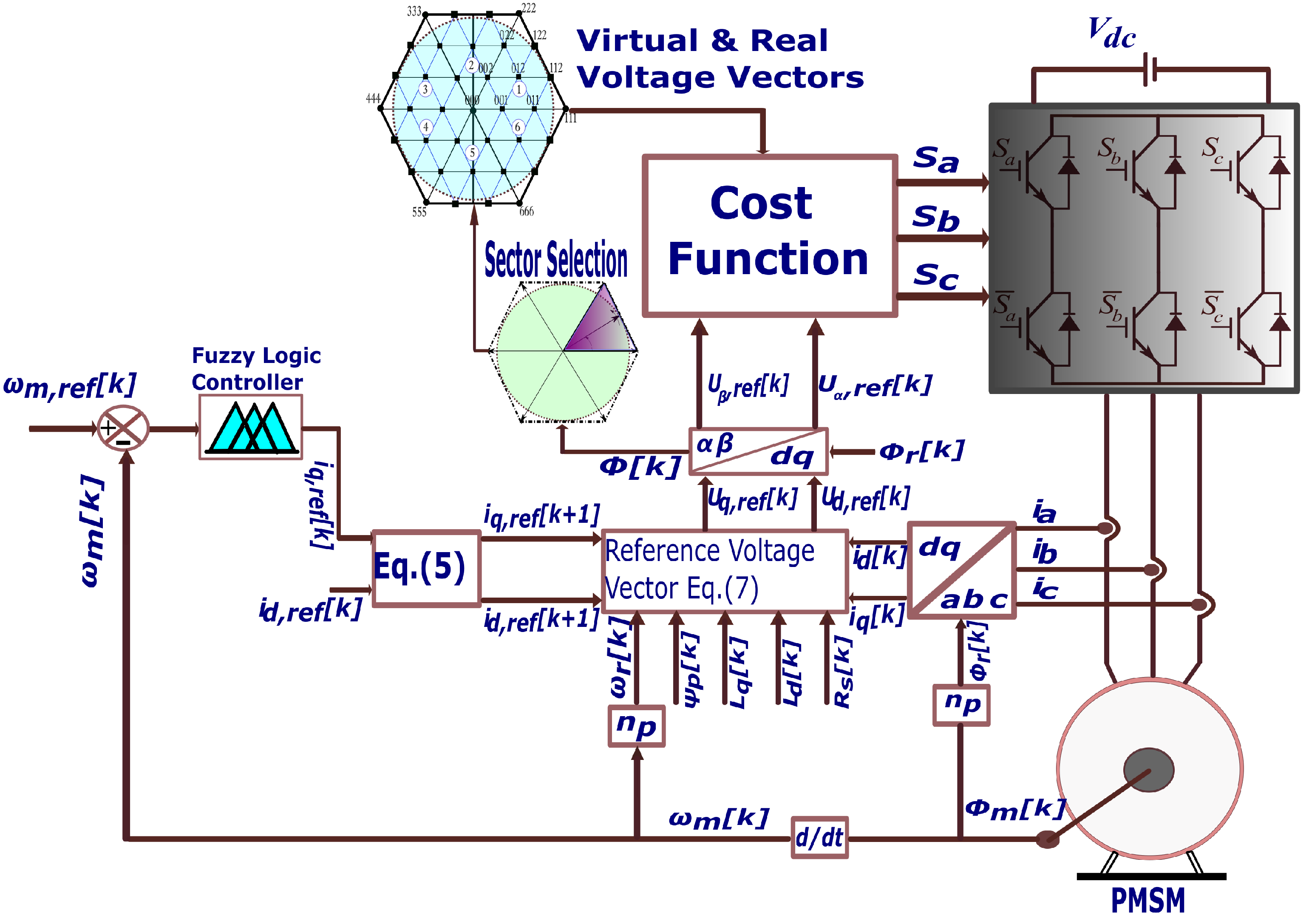
5. Fuzzy Logic Speed Control
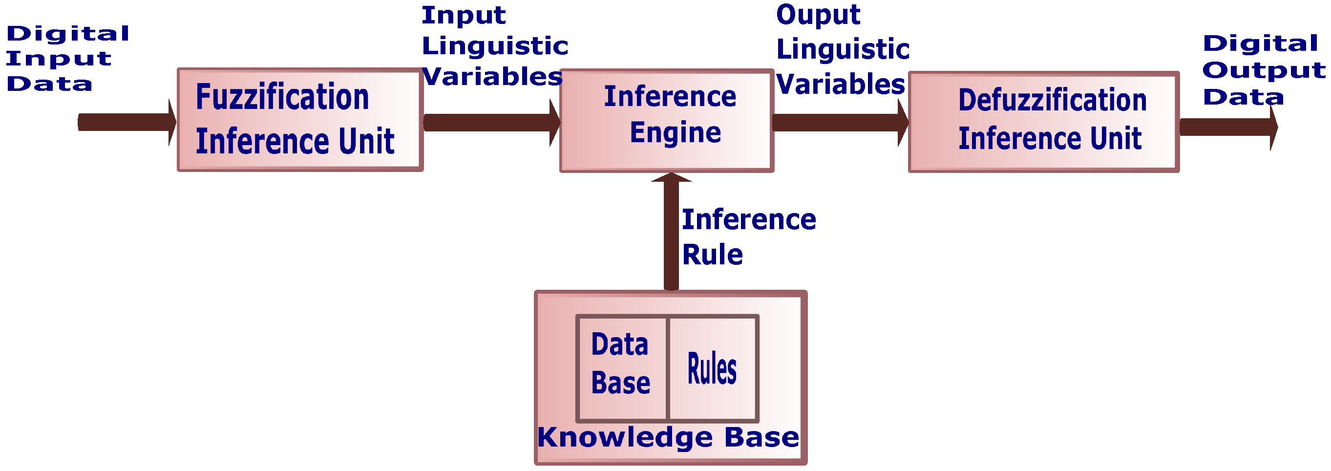
5.1. Architecture of Fuzzy Logic Control System
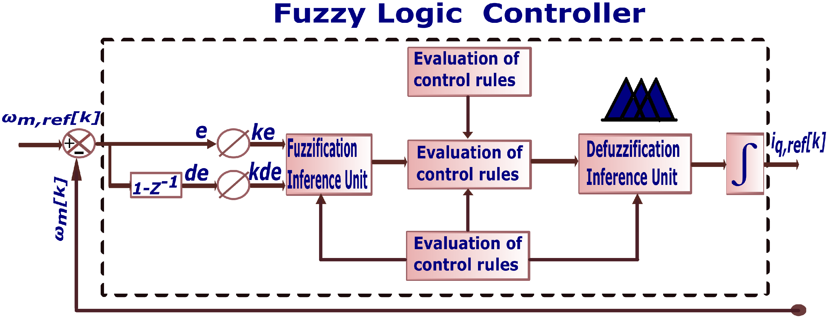
5.2. Fuzzy Logic Controller
- 1.
- If the values of e (k) and de (k) are NB, the value of the output will be NS;
- 2.
- If the values of e (k) and de (k) are PB and NM, respectively, the value of the output will be PS;
- 3.
- If the values of e (k) and de (k) are ZE and NS, respectively, the value of the output will be NS;
- 4.
- If the values of e (k) and de (k) are NS and NB, respectively, the value of the output will be NS.
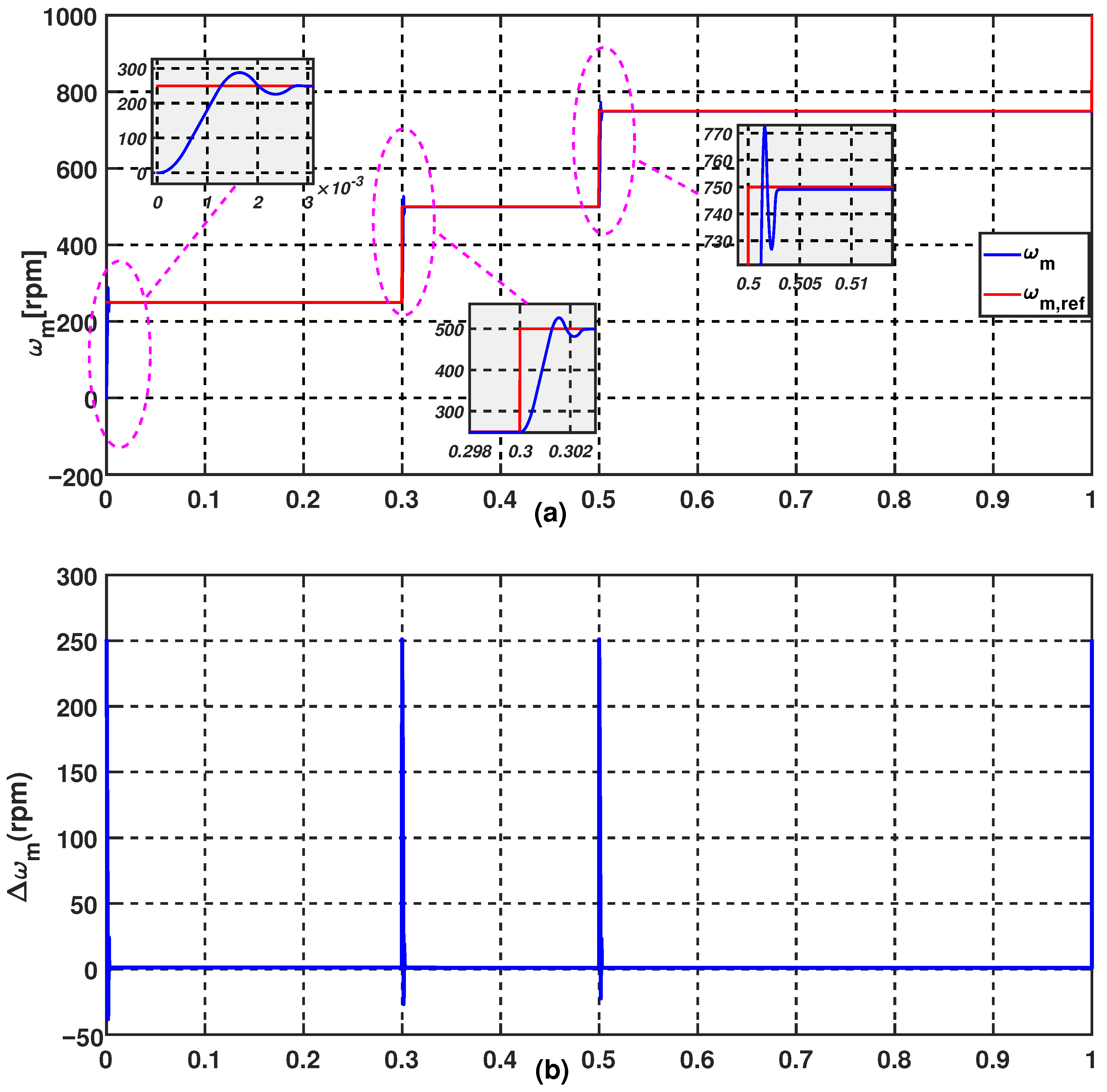
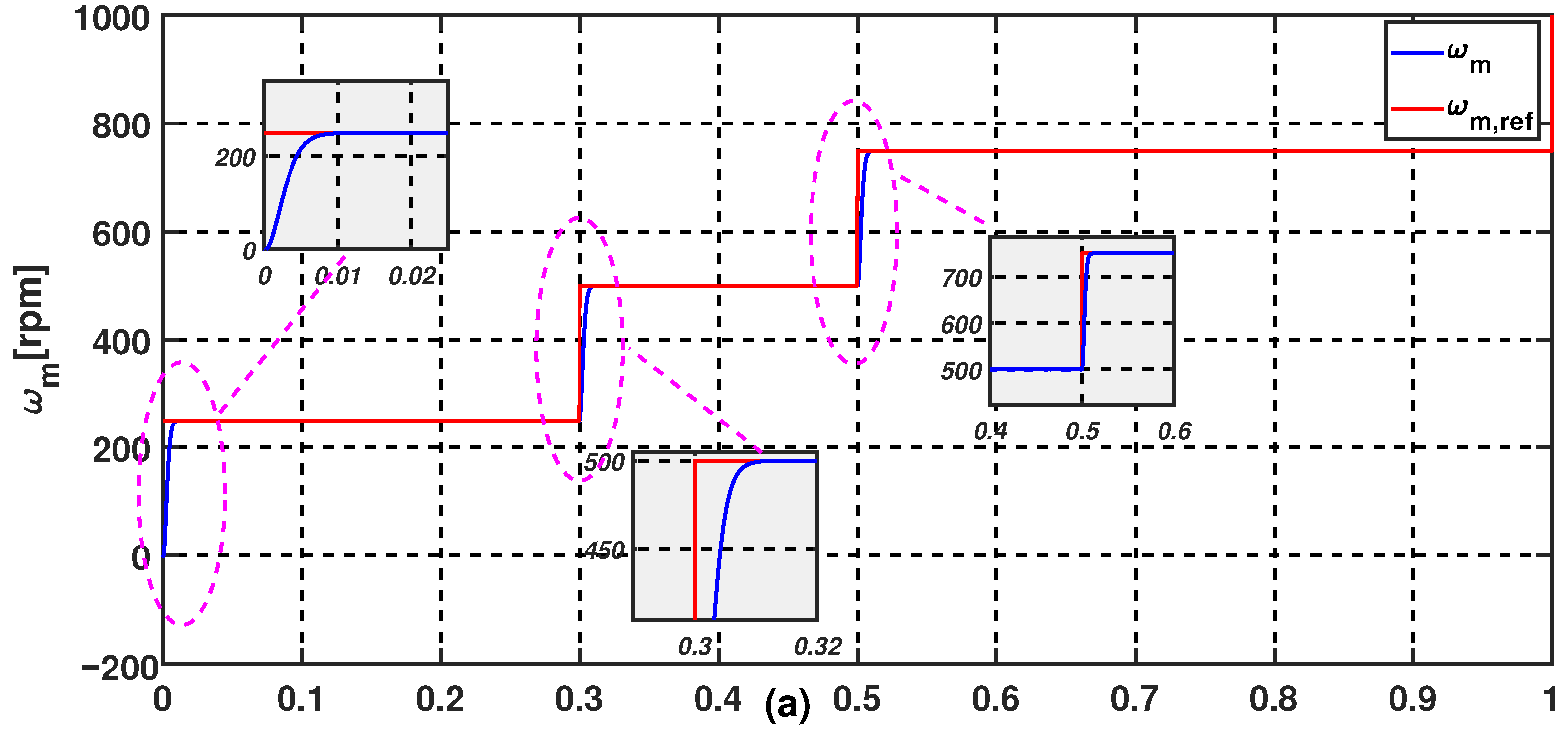
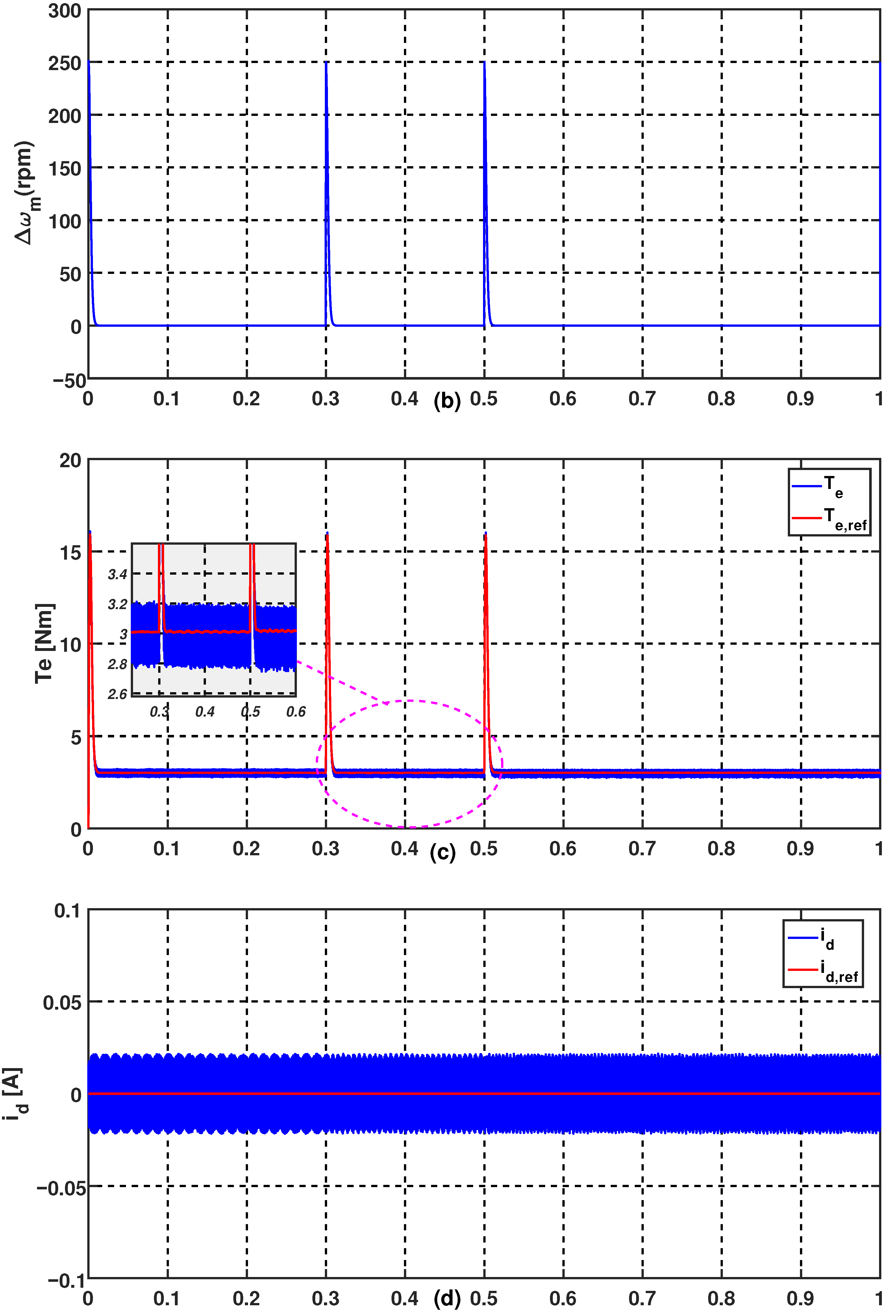
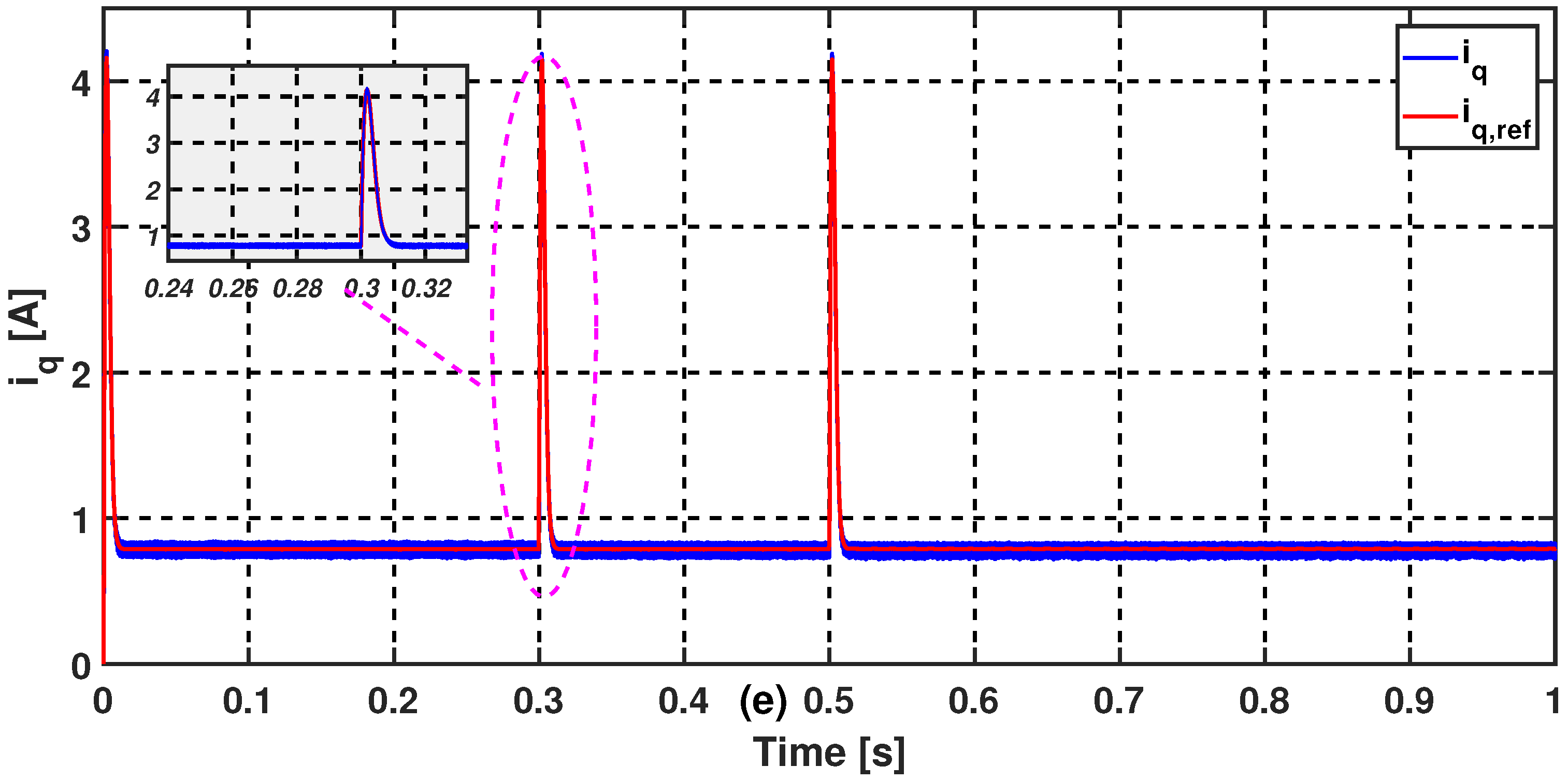
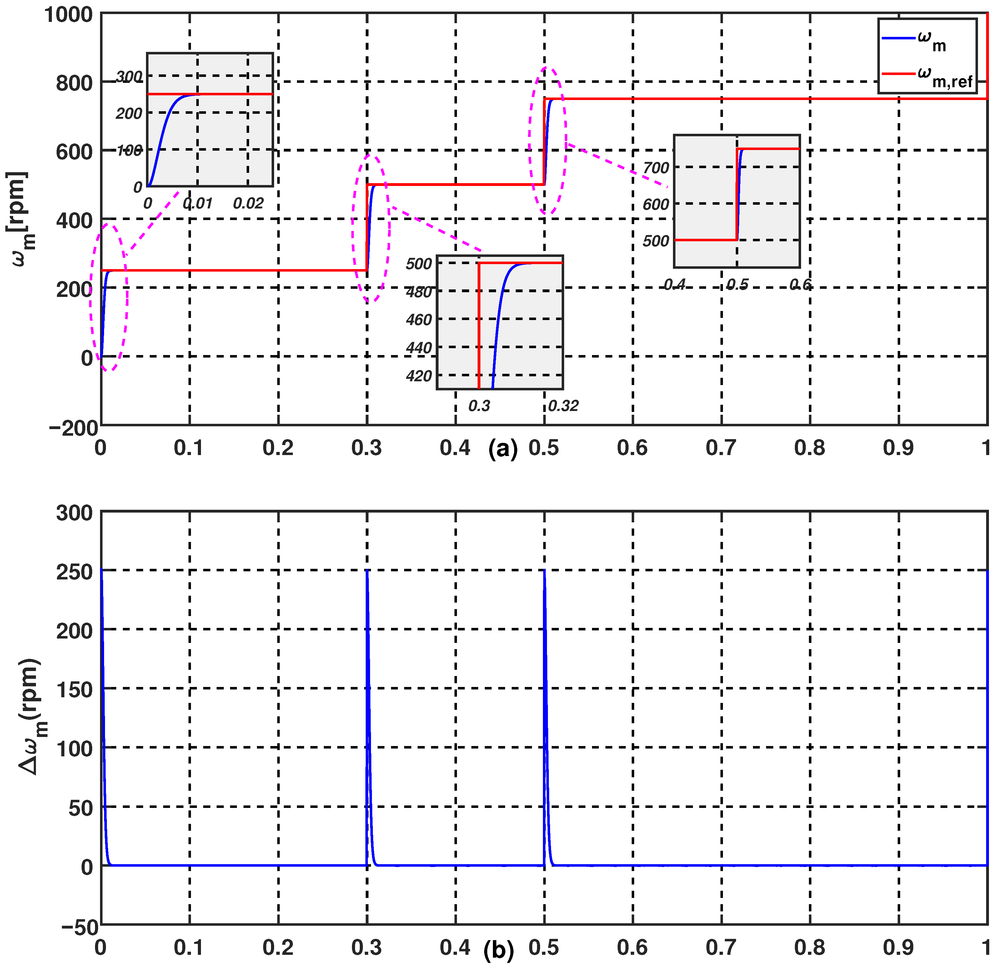
6. Simulation Results and Discussion
7. Conclusions
Author Contributions
Funding
Institutional Review Board Statement
Informed Consent Statement
Data Availability Statement
Acknowledgments
Conflicts of Interest
References
- Deng, R.; Xiang, Y.; Huo, D.; Liu, Y.; Huang, Y.; Huang, C.; Liu, J. Exploring flexibility of electric vehicle aggregators as energy reserve. Electr. Power Syst. Res. 2020, 184, 106305. [Google Scholar] [CrossRef]
- Wang, Y.; John, T.; Xiong, B. A two-level coordinated voltage control scheme of electric vehicle chargers in low-voltage distribution networks. Electr. Syst. Res. 2019, 168, 218–227. [Google Scholar] [CrossRef]
- Sufyan, M.; Rahim, N.A.; Muhammad, M.A.; Tan, C.K.; Raihan, S.R.S.; Bakar, A.H.A. Charge coordination and battery lifecycle analysis of electric vehicles with v2g implementation. Electr. Power Syst. Res. 2020, 184, 106307. [Google Scholar] [CrossRef]
- Van den Bergh, K.; Delarue, E. Energy and reserve markets: Interdependency in electricity systems with a high share of renewables. Electr. Power Syst. 2020, 189, 106537. [Google Scholar] [CrossRef]
- Salehifar, M.; Moreno-Eguilaz, M.; Putrus, G.; Barras, P. Simplified fault tolerant finite control set model predictive control of a five-phase inverter supplying bldc motor in electric vehicle drive. Electr. Power Syst. 2016, 132, 56–66. [Google Scholar] [CrossRef]
- Rodrigues, T.; Neves, G.; Gouveia, L.; Abi-Ramia, M., Jr.; Fortes, M.; Gomes, S., Jr. Impact of electric propulsion on the electric power quality of vessels. Electr. Power Syst. Res. 2018, 155, 350–362. [Google Scholar] [CrossRef]
- Xiao, X.; Zhang, Y.; Wang, J.; Du, H. New adaptive sliding-mode observer design for sensorless control of pmsm in electric vehicle drive system. Int. J. Smart Sens. Intell. Syst. 2016, 9, 377–396. [Google Scholar] [CrossRef]
- Driss, S.; Farhangi, S.; Nikzad, M.R. Low switching frequency model predictive control of pmsm drives for traction applications. In Proceedings of the 2018 9th Annual Power Electronics, Drives Systems and Technologies Conference (PEDSTC), Havez, Iran, 14–15 February 2018; pp. 300–305. [Google Scholar]
- Ayad, A.; Karamanakos, P.; Kennel, R.; Rodriguez, J. Direct model predictive control of bidirectional quasi-z-source inverters fed pmsm drives. In Proceedings of the 2017 11th IEEE International Conference on Compatibility, Power Electronics and Power Engineering (CPE-POWERENG), Cadiz, Spain, 4–6 April 2017; pp. 671–676. [Google Scholar]
- Sun, X.; Hu, C.; Zhu, J.; Wang, S.; Zhou, W.; Yang, Z.; Lei, G.; Li, K.; Zhu, B.; Guo, Y. Mptc for pmsms of evs with multi-motor driven system considering optimal energy allocation. IEEE Trans. Magn. 2019, 55, 1–6. [Google Scholar] [CrossRef]
- Yuan, X.; Zhang, S.; Zhang, C. Enhanced robust deadbeat predictive current control for pmsm drives. IEEE Access 2019, 7, 148218–148230. [Google Scholar] [CrossRef]
- Buja, G.S.; Kazmierkowski, M.P. Direct torque control of pwm inverter-fed ac motors-a survey. IEEE Trans. Ind. Electron. 2004, 51, 744–757. [Google Scholar] [CrossRef]
- Emanuele, G.; Marco, P.; Fabio, C.; Matthias, N.; Francesco, C.; Francesco, G. Detection of stator turns short-circuit during sensorless operation by means of the Direct Flux Control technique. In Proceedings of the 2020 AEIT International Annual Conference (AEIT), Catania, Italy, 23–25 September 2020; pp. 1–6. [Google Scholar]
- Pedrosa, D.; Carvalho, J.; Gonçalves, H.; Monteiro, V.; Fernandes, A.; Afonso, J.L. Field oriented control of an axial flux permanent magnet synchronous motor for traction solutions. In Proceedings of the IECON 2014—40th Annual Conference of the IEEE Industrial Electronics Society, Dallas, TX, USA, 29 October 2014; pp. 1466–1472. [Google Scholar]
- Sun, X.; Chen, L.; Yang, Z.; Zhu, H. Speed-sensorless vector control of a bearingless induction motor with artificial neural network inverse speed observer. IEEE/ASME Trans. Mechatron. 2012, 18, 1357–1366. [Google Scholar] [CrossRef]
- Yang, Y.P.; Chuang, D.S. Optimal design and control of a wheel motor for electric passenger cars. IEEE Trans. Magn. 2006, 43, 51–61. [Google Scholar] [CrossRef]
- Sun, X.; Su, B.; Wang, S.; Yang, Z.; Lei, G.; Zhu, J.; Guo, Y. Performance analysis of suspension force and torque in an ibpmsm with v-shaped pms for flywheel batteries. IEEE Trans. Magn. 2018, 54, 1–4. [Google Scholar] [CrossRef]
- Sun, X.; Chen, L.; Jiang, H.; Yang, Z.; Chen, J.; Zhang, W. High-performance control for a bearingless permanent-magnet synchronous motor using neural network inverse scheme plus internal model controllers. IEEE Trans. Ind. Electron. 2016, 63, 3479–3488. [Google Scholar] [CrossRef]
- Preindl, M.; Bolognani, S. Model predictive direct speed control with finite control set of pmsm drive systems. IEEE Trans. Power Electron. 2012, 28, 1007–1015. [Google Scholar] [CrossRef]
- Boazzo, B.; Pellegrino, G. Model-based direct flux vector control of permanent-magnet synchronous motor drives. IEEE Trans. Ind. 2015, 51, 3126–3136. [Google Scholar] [CrossRef]
- Siahbalaee, J.; Vaez-Zadeh, S.; Tahami, F. A new loss minimization approach with flux and torque ripples reduction of direct torque controlled permanent magnet synchronous motors. In Proceedings of the 2009 13th European Conference on Power Electronics and Applications, Barcelona, Spain, 8–10 September 2009; pp. 1–8. [Google Scholar]
- Abdelrahem, M.; Zhang, Z.; Kennel, R.; Eldeeb, H.; Hackl, C. Simple and robust direct-model predictive current control technique for pmsgs in variable-speed wind turbines. In Proceedings of the 2017 IEEE International Symposium on Predictive Control of Electrical Drives and Power Electronics (PRECEDE), Pilsen, Czech Republic, 4–6 September 2017; pp. 1–6. [Google Scholar]
- Gao, X.; Abdelrahem, M.; Hackl, C.M.; Zhang, Z.; Kennel, R. Direct predictive speed control with a sliding manifold term for pmsm drives. IEEE J. Emerg. Sel. Top. Power Electron. 2019, 8, 1258–1267. [Google Scholar] [CrossRef]
- Abdelrahem, M.; Hackl, C.; Kennel, R.; Rodriguez, J. Sensorless predictive speed control of permanent-magnet synchronous generators in wind turbine applications. In Proceedings of the PCIM Europe 2019, International Exhibition and Conference for Power Electronics, Intelligent Motion, Renewable Energy and Energy Management, VDE, Nuremberg, Germany, 7–9 May 2019; pp. 1–8. [Google Scholar]
- Abdelrahem, M.; Hackl, C.; Kennel, R. Model predictive control of permanent magnet synchronous generators in variable-speed wind turbine systems. In Proceedings of the Power and Energy Student Summit (PESS 2016), Aachen, Germany, 19–20 January 2016. [Google Scholar]
- Kiselev, A.; Kuznietsov, A. Motor drive control of a full-electric vehicle using generalized predictive control algorithm. In Proceedings of the 2014 IEEE International Electric Vehicle Conference (IEVC), Florence, Italy, 17–19 December 2014; pp. 1–5. [Google Scholar]
- Rodriguez, J.; Cortes, P. Predictive Control of Power Converters and Electrical Drives; John Wiley & Sons: Hoboken, NJ, USA, 2012; Volume 40. [Google Scholar]
- Cortés, P.; Kazmierkowski, M.P.; Kennel, R.M.; Quevedo, D.E.; Rodríguez, J. Predictive control in power electronics and drives. IEEE Trans. Ind. Electron. 2008, 55, 4312–4324. [Google Scholar] [CrossRef]
- Hu, J.; Zhu, Z. Improved voltage-vector sequences on dead-beat predictive direct power control of reversible three-phase grid-connected voltage-source converters. IEEE Trans. Power Electron. 2012, 28, 254–267. [Google Scholar] [CrossRef]
- Kang, J.; Li, X.; Liu, Y.; Mu, S.; Wang, S. Predictive current control with torque ripple minimization for pmsm of electric vehicles. In Proceedings of the 2018 IEEE International Power Electronics and Application Conference and Exposition (PEAC), Shenzhen, China, 4–7 November 2018; pp. 1–6. [Google Scholar]
- Hackl, C.M. Mpc with analytical solution and integral error feedback for lti mimo systems and its application to current control of grid-connected power converters with lcl-filter. In Proceedings of the 2015 IEEE International Symposium on Predictive Control of Electrical Drives and Power Electronics (PRECEDE), Valparaiso, Chile, 5–6 October 2015; pp. 61–66. [Google Scholar]
- Rodriguez, J.; Kazmierkowski, M.P.; Espinoza, J.R.; Zanchetta, P.; Abu-Rub, H.; Young, H.A.; Rojas, C.A. State of the art of finite control set model predictive control in power electronics. IEEE Trans. Ind. 2012, 9, 1003–1016. [Google Scholar] [CrossRef]
- Garcia, C.; Rodriguez, J.; Odhano, S.; Zanchetta, P.; Davari, S.A. Modulated model predictive speed control for pmsm drives. In Proceedings of the 2018 IEEE International Conference on Electrical Systems for Aircraft, Railway, Ship Propulsion and Road Vehicles & International Transportation Electrification Conference (ESARS-ITEC), Nottingham, UK, 7–9 November 2018; pp. 1–6. [Google Scholar]
- Van Ngo, B.Q.; Rodriguez-Ayerbe, P.; Olaru, S. Model predictive control with two-step horizon for three-level neutral-point clamped inverter. In Proceedings of the 20th International Conference on Process Control (PC), Štrbské Pleso, Slovak Republic, 9–12 June 2015; pp. 215–220. [Google Scholar]
- Vázquez Pérez, S.; Rodríguez, J.; Rivera, M.; García Franquelo, L.; Norambuena, M. Model predictive control for power converters and drives: Advances and trends. IEEE Trans. Ind. 2017, 64, 935–947. [Google Scholar] [CrossRef]
- Zhang, Y.; Xie, W.; Li, Z.; Zhang, Y. Low-complexity model predictive power control: Double-vector-based approach. IEEE Trans. Ind. 2014, 61, 5871–5880. [Google Scholar] [CrossRef]
- Riar, B.S.; Scoltock, J.; Madawala, U.K. Model predictive direct slope control for power converters. IEEE Trans. Power Electron. 2017, 32, 2278–2289. [Google Scholar] [CrossRef]
- Zhang, Y.; Yang, H. Two-vector-based model predictive torque control without weighting factors for induction motor drives. IEEE Trans. Power Electron. 2016, 31, 1381–1390. [Google Scholar] [CrossRef]
- Sheng, L.; Li, D.; Ji, Y. Two-vector fcs-mpc for permanent-magnet synchronous motors based on duty ratio optimization. Math. Probl. Eng. 2018, 2018, 9061979. [Google Scholar] [CrossRef]
- Zhang, Y.; Gao, S.; Xu, W. An improved model predictive current control of permanent magnet synchronous motor drives. In Proceedings of the 2016 IEEE Applied Power Electronics Conference and Exposition (APEC), Long Beach, Canada, 20–24 March 2016; pp. 2868–2874. [Google Scholar]
- Rodríguez, J.; Kennel, R.M.; Espinoza, J.R.; Trincado, M.; Silva, C.A.; Rojas, C.A. High-performance control strategies for electrical drives: An experimental assessment. IEEE Trans. Ind. Electron. 2012, 59, 812–820. [Google Scholar] [CrossRef]
- Abdelrahem, M.; Hackl, C.M.; Kennel, R.; Rodriguez, J. Efficient direct-model predictive control with discrete-time integral action for pmsgs. IEEE Trans. Energy Convers. 2018, 34, 1063–1072. [Google Scholar] [CrossRef]
- Zhang, Y.; Xu, D.; Liu, J.; Gao, S.; Xu, W. Performance improvement of model-predictive current control of permanent magnet synchronous motor drives. IEEE Trans. Ind. Appl. 2017, 53, 3683–3695. [Google Scholar] [CrossRef]
- Vazquez, S.; Leon, J.I.; Franquelo, L.; Carrasco, J.; Martinez, O.; Rodriguez, J.; Cortes, P.; Kouro, S. Model predictive control with constant switching frequency using a discrete space vector modulation with virtual state vectors. In Proceedings of the 2009 IEEE International Conference on Industrial Technology, Churchill, VIC, Australia, 10–13 February 2009; pp. 1–6. [Google Scholar]
- Zhang, Y.; Bai, Y.; Yang, H. A universal multiple-vector-based model predictive control of induction motor drives. IEEE Trans. Power Electron. 2017, 33, 6957–6969. [Google Scholar] [CrossRef]
- Habibullah, M.; Lu, D.D.C.; Xiao, D.; Rahman, M.F. A simplified finite-state predictive direct torque control for induction motor drive. IEEE Trans. Ind. Electron. 2016, 63, 3964–3975. [Google Scholar] [CrossRef]
- Hassine, I.M.B.; Naouar, M.W.; Mrabet-Bellaaj, N. Model predictive-sliding mode control for three-phase grid-connected converters. IEEE Trans. Ind. Electron. 2017, 64, 1341–1349. [Google Scholar] [CrossRef]
- Zhang, Y.; Xu, D.; Huang, L. Generalized multiple-vector-based model predictive control for pmsm drives. IEEE Trans. Ind. Electron. 2018, 65, 9356–9366. [Google Scholar] [CrossRef]
- Xie, W.; Wang, X.; Wang, F.; Xu, W.; Kennel, R.; Gerling, D.; Lorenz, R. Finite-control-set model predictive torque control with a deadbeat solution for PMSM drives. IEEE Trans. Ind. Electron. 2015, 62, 5402–5410. [Google Scholar] [CrossRef]
- Zhang, X.; Hou, B. Double vectors model predictive torque control without weighting factor based on voltage tracking error. IEEE Trans. Power Electron. 2018, 33, 2368–2380. [Google Scholar] [CrossRef]
- Zhang, X.; He, Y. Direct voltage-selection based model predictive direct speed control for PMSM drives without weighting factor. IEEE Trans. Power Electron. 2019, 34, 7838–7851. [Google Scholar] [CrossRef]
- Wang, Y.; Wang, X.; Xie, W.; Wang, F.; Dou, M.; Kennel, R.; Lorenz, R.D.; Gerling, D. Deadbeat model-predictive torque control with discrete space-vector modulation for PMSM drives. IEEE Trans. Ind. Electron. 2017, 64, 3537–3547. [Google Scholar] [CrossRef]
- Abdelrahem, M.; Rodríguez, J.; Kennel, R. Improved Direct Model Predictive Control for Grid-Connected Power Converters. Energies 2020, 13, 2597. [Google Scholar] [CrossRef]
- Bouguenna, I.F.; Azaiz, A.; Tahour, A.; Larbaoui, A. Robust neuro-fuzzy sliding mode control with extended state observer for an electric drive system. Energy 2019, 169, 1054–1063. [Google Scholar] [CrossRef]
- Singh, B.; Goyal, D. Improved dsvm-dtc based current sensorless permanent magnet synchronous motor drive. In Proceedings of the 2007 7th International Conference on Power Electronics and Drive Systems, Bangkok, Thailand, 27–30 November 2007; pp. 1354–1360. [Google Scholar]
- Sun, Y.; Zhai, S.; Cui, H.; Nan, D.; Wang, K. Frequency regulation strategy for private evs participating in integrated power system of res considering adaptive markov transition probability. Electr. Power Syst. Res. 2019, 173, 291–301. [Google Scholar] [CrossRef]
- Mansour, M.; Mansouri, M.; Bendoukha, S.; Mimouni, M. A grid-connected variable-speed wind generator driving a fuzzy-controlled pmsg and associated to a flywheel energy storage system. Electr. Power Syst. Res. 2020, 180, 106137. [Google Scholar] [CrossRef]
- Maamoun, A.; Alsayed, Y.; Shaltout, A. Fuzzy logic based speed controller for permanent-magnet synchronous motor drive. In Proceedings of the 2013 IEEE International Conference on Mechatronics and Automation, Takamatsu, Japan, 4–7 August 2013; pp. 1518–1522. [Google Scholar]
- Rashid, G.; Ali, M.H. Fault ride through capability improvement of dfig based wind farm by fuzzy logic controlled parallel resonance fault current limiter. Electr. Power Syst. Res. 2017, 146, 1–8. [Google Scholar] [CrossRef]
- Faddel, S.; Mohamed, A.A.; Mohammed, O.A. Fuzzy logic-based autonomous controller for electric vehicles charging under different conditions in residential distribution systems. Electr. Power Syst. Res. 2017, 148, 48–58. [Google Scholar] [CrossRef]
- Bouzeria, H.; Fetha, C.; Bahi, T.; Abadlia, I.; Layate, Z.; Lekhchine, S. Fuzzy logic space vector direct torque control of pmsm for photovoltaic water pumping system. Energy Procedia 2015, 74, 760–771. [Google Scholar] [CrossRef]


| Conducting Modes | Switching States | Output Voltage | |||
|---|---|---|---|---|---|
| 0 | 0 | 0 | 0 | 0 | |
| 1 | 0 | 0 | 0 | ||
| 1 | 1 | 0 | |||
| 0 | 1 | 0 | |||
| 0 | 1 | 1 | 0 | ||
| 0 | 0 | 1 | |||
| 1 | 0 | 1 | |||
| 1 | 1 | 1 | 0 | 0 | |
| e | NB | NM | NS | ZE | PS | PM | PB |
|---|---|---|---|---|---|---|---|
| de | |||||||
| NB | NS | NS | NS | NB | NM | NS | ZE |
| NM | NS | NS | NB | NM | NS | ZE | PS |
| NS | NS | NB | NM | NS | ZE | PS | PM |
| ZE | NB | NM | NS | ZE | PS | PM | PB |
| PS | NM | NS | ZE | PS | PM | PB | PS |
| PM | NS | ZE | PS | PM | PB | PS | PB |
| PB | ZE | PS | PM | PB | PS | PB | PB |
| Variable | Symbol | Value |
|---|---|---|
| d axis inductance [] | 15 | |
| q axis inductance [] | 15 | |
| Flux induced by magnets [] | 0.85 | |
| Number of poles | 3 | |
| Rotor inertia [] | 0.002 | |
| viscous friction [] | 0.0015 | |
| Stator resistance [] | 0.2 | |
| Rated power [kw] | P | 16 |
| DC-link [] | 560 | |
| Sampling time for all methods [] | 40 |
Publisher’s Note: MDPI stays neutral with regard to jurisdictional claims in published maps and institutional affiliations. |
© 2021 by the authors. Licensee MDPI, Basel, Switzerland. This article is an open access article distributed under the terms and conditions of the Creative Commons Attribution (CC BY) license (http://creativecommons.org/licenses/by/4.0/).
Share and Cite
Bouguenna, I.F.; Tahour, A.; Kennel, R.; Abdelrahem, M. Multiple-Vector Model Predictive Control with Fuzzy Logic for PMSM Electric Drive Systems. Energies 2021, 14, 1727. https://doi.org/10.3390/en14061727
Bouguenna IF, Tahour A, Kennel R, Abdelrahem M. Multiple-Vector Model Predictive Control with Fuzzy Logic for PMSM Electric Drive Systems. Energies. 2021; 14(6):1727. https://doi.org/10.3390/en14061727
Chicago/Turabian StyleBouguenna, Ibrahim Farouk, Ahmed Tahour, Ralph Kennel, and Mohamed Abdelrahem. 2021. "Multiple-Vector Model Predictive Control with Fuzzy Logic for PMSM Electric Drive Systems" Energies 14, no. 6: 1727. https://doi.org/10.3390/en14061727
APA StyleBouguenna, I. F., Tahour, A., Kennel, R., & Abdelrahem, M. (2021). Multiple-Vector Model Predictive Control with Fuzzy Logic for PMSM Electric Drive Systems. Energies, 14(6), 1727. https://doi.org/10.3390/en14061727