1. Introduction
The pulp and paper industry is one of the largest global industrial sectors in terms of energy use [
1]. Most of the energy demand is fulfilled by burning black liquor, a liquid byproduct from extracting the fibers from wood in a kraft pulping process, in recovery boilers [
2]. The liquor contains both the used pulping chemicals to be recovered and about half of the organic matter in wood, particularly lignin. Combustion of this liquor in a kraft recovery boiler achieves two goals—regenerating the pulping chemicals and recovering a significant amount of energy by burning the organics. In forested countries with large pulp and paper industries such as Finland, black liquor can amount to more than half of all renewable fuel sources in heat and power generation in terms of energy content [
3]. Although the pulping process is energy-intensive and consumes considerable amounts of both electricity and heat, the energy from black liquor combustion is enough to make a kraft pulp mill, typically a net energy producer, able to sell electricity to the national grid.
The pulp and paper industry is under pressure to meet the demands of a competitive and sometimes volatile market, in addition to the societal pressure both in the form of regulations and public image to reduce the environmental impacts of the production. A number of measures have been studied in search of improved profitability and sustainability, including diversifying production to other products such as biofuels [
4], alternative chemical recovery technologies such as black liquor gasification [
5], separating lignin [
6] and other valuable materials [
7] from the black liquor, and recently also carbon capture and storage (CCS) [
8], to name a few. As the process is energy-intensive, energy efficiency, in particular, has been widely studied. The clear majority of these studies have focused on the pulp mill itself—various pinch and bridge analyses have been conducted and published as case studies, e.g., [
9,
10]; the potential of absorption heat pumps for reducing the energy demand has been considered both as case examples for individual applications [
11] and as part of a pinch analysis [
12], elimination of non-isothermal mixing of flows has been conducted [
13], optimal values of key process parameters such as steam pressure levels [
14] have been studied, and the configurations of large steam consumers such as the evaporator plant have been optimized [
15].
Even though the explicit or indirect goal of many energy efficiency studies has been the reduction of the steam consumption of the pulp mill processes for the purpose of increased net power generation, the recovery boiler and the steam cycle have received much less attention in comparison. Achieving high electrical efficiencies in kraft pulp mill steam cycles is curbed by the significant steam use of the mill itself and by relatively modest live steam values available from the recovery boiler. This is necessitated by the corrosive nature of the flue gases rich with sulfur, chlorine, and alkaline metals [
16]. The live steam temperatures in new boilers have gradually improved over the years [
17] but remain well below those of other types of biomass-fired boilers.
Although improving steam parameters has been a focus area in efforts to improve recovery boiler performance, a significant amount of energy in conventional recovery boilers is also lost when flue gases are released through the stack to the atmosphere. In the past, the acid dew point limited the flue gas exit temperature to higher values than was typically possible with other types of biomass boilers [
18]. Significant energy can be recovered by further cooling the flue gases [
19], translating to increased power generation and electricity sales revenue. Additional savings can be achieved if the flue gas is cooled below the dew point. Due to the combination of the low temperature of the recovered heat and the cost of materials needed to prevent corrosion problems, this has not been a common approach in the past, however. Even though some recovery boilers have been equipped with scrubbers that incorporate flue gas condensation and heat recovery, the configurations are typically simple and oriented toward gas cleaning and simplicity rather than heat recovery and high energy efficiency.
In recent years, the increased emphasis on energy efficiency and renewable energy has created interest in low-grade heat recovery by flue gas condensation in many applications. Han et al. studied water and heat recovery in a large-scale power plant application utilizing high-moisture lignite fuel [
20], Liu et al. investigated a packed bed scrubber for coal-fired power plants with oxy-fuel CCS and air-combustion boiler [
21], Hebenstreit et al. performed a techno-economic study of a small-scale biomass boiler with heat recovery by flue gas condensation [
22], and Terhan and Comakli studied flue gas condensers in a 60 MW gas-fired boiler [
23]. In the Nordic countries increasing numbers of biomass-fired boilers are being equipped with condensing back-end heat recovery systems, similar to that presented by Teppler et al. [
24]. Earlier, the authors of this paper considered a heat recovery scheme based on scrubbers as part of a CCS scheme based on biomass chemical looping combustion with oxygen uncoupling (CLOU) [
25]. A shared characteristic of all aforementioned applications is high flue gas moisture, whether due to fuel moisture (biomass or lignite), hydrogen in the fuel (natural gas or biomass), or a lack of atmospheric nitrogen (oxy-combustion and CLOU).
Different heat sinks can be considered for the recovered heat; some studies have considered boilers for district heating, in which the return water from the district heating network is the heat sink, while in [
20], the main condensate stream of a power plant steam cycle was identified as a potential heat sink. Even though the water vapor in flue gases typically has a considerable amount of latent heat available, the dew point sets an upper limit to the temperature of the recovered heat. This restricts the possible heat sinks in all applications. To circumvent this limitation, many studies, including [
20,
22,
24], have considered heat pumps as a way to increase the possibilities for heat recovery. Both compression and absorption heat pumps have been installed in operational heat-only boilers for reducing fuel consumption through improved efficiency in heat generation.
Several studies have evaluated the potential benefits of flue gas condensation in a number of applications. Different aspects of pulp mill energy efficiency improvement potential have also been investigated, but as of yet, there are no published works focusing on the application of flue gas condensation in a recovery boiler. The purpose of this study is to address this research gap by investigating the technical potential for increased power generation through condensing waste heat recovery from kraft recovery boiler flue gas. The study is limited to direct-contact condensation in counter-current, packed bed quench scrubbers. Different configurations of heat recovery equipment and different possible heat sinks are evaluated. In addition to using a number of possible heat sinks in the steam cycle for heat recovery, the pulp mill is considered as a potential user of the recovered heat, and the potential of compression heat pumps to augment the recovery of the relatively low-grade heat is evaluated.
2. Methods
2.1. Modeling Software
The boiler, steam cycle, and heat recovery equipment are modeled using IPSEpro, a steady-state, equation-oriented commercial process simulation software for simulation and design of power plants [
26,
27] by SimTech GmbH, Graz, Austria. In the IPSEpro environment, the overall plant flowsheet models are constructed using discrete modules representing individual power plant and boiler components, which are connected by streams. Each component model consists of a set of equations describing the behavior of the component. These equations, together with any additional free equations the user may define, form the system of nonlinear equations that is the plant model. This is solved in IPSEpro by first dividing the equations into groups and then solving the groups consecutively with a Newton–Raphson-based solver [
28].
The IPSEpro software includes a Model Development Kit (MDK), which allows modifying the existing standard library components, or creating new component modules not included in the standard power plant component library. The MDK was used to create the recovery boiler furnace module and the spray tower and humidifier modules used in this study.
In comparison to a similar equation-oriented power plant simulation software, IPSEpro has been found competitive in terms of performance; it is significantly faster at finding the solution [
28] with very small differences in the results judged to have been caused mainly by the other software failing to precisely converge by the time the solver algorithm stopped [
28]. The main shortcoming of IPSEpro noted in [
28], and also observed in the process of this research, is due to the gradient-based Newton–Raphson solver needing a good initial guess of the solution to converge. Even though this makes major changes to a complex model a tedious, time-consuming process of many small consecutive changes to find the initial guess for the next small change, the accuracy of calculation is not compromised—once the solver does converge, it does so quickly and to a very high degree accuracy. The combination of accurate solutions and full transparency of the equations behind the component models to the user effectively removes the simulation tool as a potential source of errors in the calculation.
2.2. Flue Gas Cooling, Condensation, and Heat Recovery
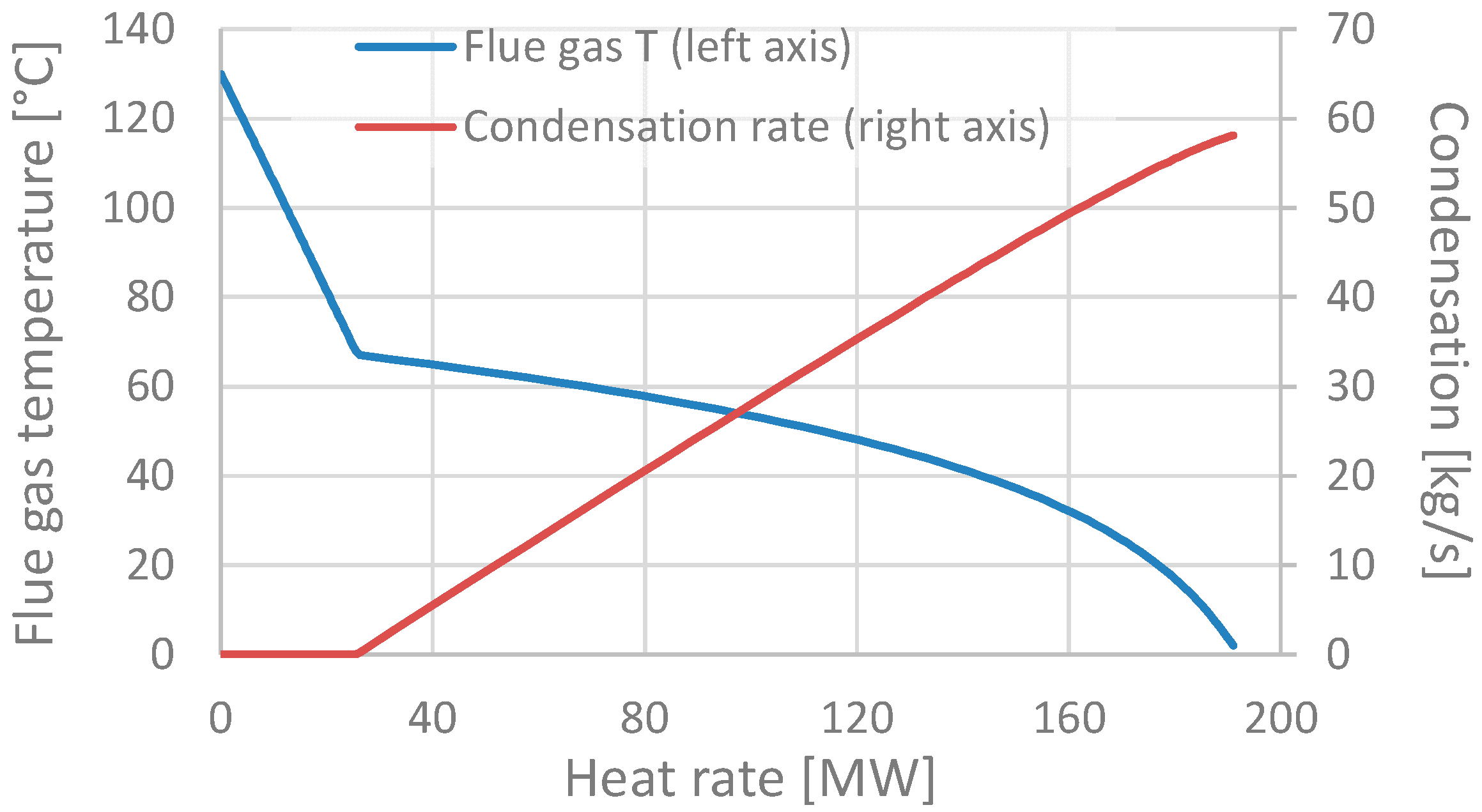
When recovery boiler flue gases are cooled further after the economizer, the first regime is non-condensing, operating above flue gas water dew point, 70–75 °C. The gases can be cooled by surface heat exchangers, with an indirect connection to target media (e.g., combustion air or steam cycle water) using an indirect connection with water as a heat transfer medium [
19]. The second regime is one of condensation; much more heat can be recovered by condensation, albeit at a clearly lower temperature. This is demonstrated in
Figure 1 for a 358 kg/s flue gas flow corresponding to the case considered in this study. Typically condensing is implemented with a scrubber with an indirect connection to the target media, as the flue gases still contain impurities such as dust.
Two different cases of condensing heat recovery schemes are considered; these are depicted in
Figure 2. The simple scrubber scheme (“S1” in
Figure 2) is representative of equipment currently used in those recovery boilers that are equipped with scrubbers. The main purpose of this is typically gas cleaning, and heat recovery is often implemented through a simple warm-water tank serving as a heat sink for cooling the water from the bottom of the tower as it is pumped up to be sprayed again. For enhanced heat recovery, a packed-bed device can be used for increased water–gas contact area. The low temperature of the recovered water, typically approximately 60 °C, means that these schemes are often limited by the availability of low-temperature heat sinks.
Utilizing some of the recovered heat for combustion air humidification allows further flue gas cooling and condensation while increasing the heat recovery temperature due to increased water partial pressure in the flue gases. Humidification is considered in conjunction with a two-stage packed bed scrubber to increase further the temperature of the water collected from the lower scrubber (“S2H” in
Figure 2). Finally, even though not depicted in
Figure 2 as the spray tower configurations remain unaffected, heat pumps can be used to upgrade the recovered heat to a higher temperature. In this study, compression heat pumps are considered in conjunction with both configurations.
2.3. Studied Case
The studied case is a large Nordic pulp mill producing 1.6 million ADt of pulp annually during 350 days of operation. The energy consumptions are assumed similar to those reported in [
8], at 0.83 MWh/ADt of 12 bar(a) MP steam and 1.8 MWh/ADt of 5 bar(a) LP steam. The specific electricity consumptions are 0.584 MWh/ADt and 0.020 MWh/ADt for the pulp mill and adjacent oxygen, hydrogen peroxide, and ClO
2 plants, respectively [
8]. Black liquor production is 1.5 t
BL,ds/ADt;
Table 1 shows the firing liquor dry matter composition after mixing with the ash from the recovery boiler.
The flowsheet of the basic version of the investigated plant is presented in
Figure 3. The recovery boiler considered is a modern one, with live steam parameters of 100 bar(a) and 510 °C. A single high-pressure feedwater preheater operating with 12 bar extraction steam is used to heat the boiler feedwater to 186 °C before economizer. There are no low-pressure preheaters before the deaerator; the main condensate is heated only by sealing and leakage steam condenser, hot water from blowdown, and a dry heat recovery (“D”) scheme without flue gas condensation.
The case “D” depicted in the figure is a typical configuration for modern recovery boilers with feedwater preheated to a comparatively high temperature before the economizer but without a scrubber. Flue gas temperature after economizer is still relatively high at slightly over 200 °C; from this temperature, the gases are cooled to 130 °C using an indirect water loop. The water in the gas–water heat exchanger is maintained at above 110 °C to prevent condensation and risk of corrosion at the surfaces. Temperature is maintained at a safe level by mixing 140 °C water after the heat exchanger with the cold return water arriving back from having been used for heating combustion air and the main condensate stream.
2.4. Boiler Model
The recovery boiler model is composed of a furnace model, followed in flue gas flow direction by separate heat exchanger modules representing the superheater, economizer, and the hot-water heat recovery heat exchanger described above, placed after the electrostatic precipitators. Air preheating takes place with steam and hot water only, without an air preheater as used in conventional biomass boilers. The heat losses with ash, smelt, reduction reactions, and radiation losses are determined in the furnace model, developed using the IPSEpro MDK kit.
The boiler model calculation methodology is based on that described in [
17]. Firing liquor dry solids content of
xds = 0.83 and temperature of 140 °C is considered. The higher heating value (HHV) of the black liquor [MJ/kg] is determined according to [
2] from
where
CX is the mass fraction of species x in the dry solids [kg
x/kg
ds]. With the composition of
Table 1, this yields a wet firing liquor lower heating value of LHV = 9.9 MJ/kg at the 0.83 dry solids content. Black liquor enthalpy
hBL is determined as in [
15]—first, a value for the enthalpy at 80 °C is obtained according to [
29],
where
xds is the dry solids fraction, and this is corrected to actual temperature with a correlation for
cp,bl [kJ/kgK] by Masse et al. [
30] as cited in [
2],
where
t is temperature [°C].
The flue gas, ash, and smelt compositions are determined from species balances according to the methodology presented in [
17]. A reduction efficiency of
ηr = 0.94 is considered, defined as the molar ratio of sulfides to total sulfur in the smelt,
A significant amount of the black liquor chemicals end up in the ash rather than the smelt. The ash is mostly recovered from the back pass and the electrostatic precipitators and recycled back into the pulping process, typically in the evaporator plant. The smelt and ash compositions are listed in
Appendix A; the total flows are 35.6 kg/s of smelt and 8.7 kg/s of ash. The smelt and ash are assumed to have specific heats of 1.42 kJ/kgK and 1.2 kJ/kgK, respectively. The smelt exits the furnace at 980 °C, resulting in a considerable sensible heat loss in addition to the endothermic reduction reactions to sulfides.
Finally, the radiation and conduction loss
is estimated according to [
31] as a function of total useful heat output to steam cycle and blowdown
,
and 3.85 MW of unaccounted losses is assumed based on [
17].
Flue gas is assumed to exit the furnace at a temperature of approximately 1100 °C to the superheaters and the economizer. The models of these are otherwise similar to those described in [
32] for a fluidized bed boiler but include sootblowing steam becoming mixed with the flue gas flow. The sootblowing is performed with 27 bar(a) extraction steam from the turbine. The air preheating is implemented by means of steam coil air heaters (SCAH). The 25 °C ambient air is heated to 200 °C temperature before entering the furnace. Air heating is performed in multiple stages, with a high-pressure (HP) SCAH using 27 bar(a) steam always as the final stage. Earlier stages are implemented using various combinations of 11 bar(a) MP steam, hot water heated with the flue gas, and hot water from the scrubbers. An excess air ratio of
λ = 1.18 is assumed. The inputs, useful outputs, and losses according to the boiler model for the considered case are summarized in
Table 2.
The boiler fan power consumptions are calculated assuming isentropic compression efficiencies of 0.80 and electromechanical efficiencies of 0.97 for both forced and induced draft fans, an overpressure of 20 mbar in the furnace windboxes, and a 7 mbar overpressure at the entry to stack.
2.5. Steam Cycle Model
The steam cycle modeling is based on that presented in [
32]. The turbine model assumes at optimal flow rate dry isentropic expansion efficiency
ηs increasing from 0.86 in the first HP turbine work stage module to 0.90 in the low-pressure (LP) turbine modules, for overall values of
ηs = 0.87 in the HP turbine (including governing stage) and 0.82 in the LP turbine (including effects of moisture and exhaust and hood losses). Dry efficiency variation due to mass flow rate change is estimated according to a correlation from Jüdes et al. [
33] and corrected for possible moisture according to [
34], when applicable. The variation of pressure ratios as a function of mass flow is modeled with the ellipse law by Traupel [
35]. More detailed descriptions of the models can be found in [
32]. Expansion ends at a condenser with 3250 m
2 area and 3.0 kW/m
2 K overall heat transfer coefficient at design conditions of 24 mbar, 49 kg/s steam, and 2700 kg/s coolant flow.
Turbine sealing steam flow of 0.5% of the average flow through the HP turbine is assumed to be fully recovered. This is used for main condensate pre-heating, increasing the temperature of combined turbine condensate, and mill condensate returns from 50 °C to 54 °C. The main condensate temperature to the 4.2 bar(a) deaerator after mixing with makeup water and further pre-heating through the liquid from blowdown flashing and dry recovery scheme hot-water heating is 49 °C. The final stage of feedwater heating is the 1310 m2 HP closed feed heater, operated with 11 bar steam for terminal temperature difference TTD = 1 °C, and 186 °C, and 116 bar(a) final feedwater state before the boiler.
2.6. Condensing Heat Recovery System and Component Models
Condensing heat recovery can be implemented either in a surface condenser or through direct-contact condensation in scrubbers. In recent years, heat recovery scrubbers have become increasingly common in new small-scale biomass combustion plants, particularly in heat-only boilers for district heat generation. In those recovery boilers in which scrubbers have been installed, their primary function is typically that of final gas cleaning after the electrostatic precipitators, with a relatively simple heat recovery implementation.
Heat recovery scrubbers are typically implemented as spray towers using packed beds of filler elements. Water is sprayed from above in the counter-flow direction to the upward-flowing flue gas. The filler elements form a water pellicle on their surface, increasing the water–gas contact area. In order to achieve a small droplet size, typically a pressure of approximately 2–3 bar is kept at the spray nozzles; 2-bar pressure is considered here. As the main mode of heat transfer is condensation, the relative humidity of the gas at exit is approximately 100%.
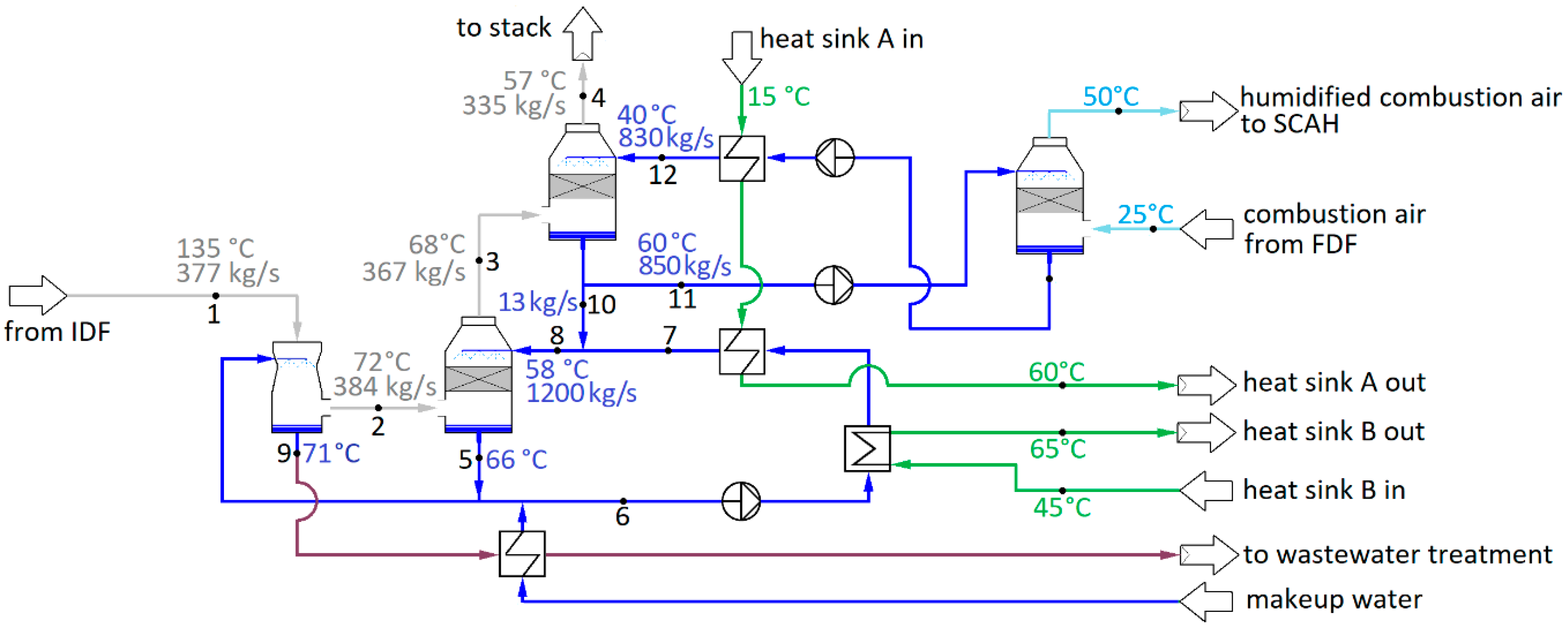
By spraying water into the gas also before the packed bed, the gas can be both cleaned and cooled, thereby reducing volumetric flow rate, permitting lower-cost materials and smaller equipment sizing, and also reducing fouling in the heat recovery system. This can be implemented simply as another spray system below the packed bed in the spray tower, or in a separate emission control scrubber (ECS) unit prior to gas entry to the spray tower. In this study, a separate scrubber is considered; this allows maintaining cleaner water circulating in the spray tower and the related heat exchangers, reducing fouling and making close temperature approaches in the heat exchangers easier to achieve. The modeling implementation of the heat recovery system is shown in
Figure 4.
The depicted example shows the two-stage heat recovery spray tower with humidification, corresponding to the “S2H” configuration of
Figure 2. Mass flow rates of spray water in the figure represent values used in the simulations, slight variations due to varying amounts of condensation and evaporation in the heat recovery scrubber (HRS) and combustion air humidifier (CAH) notwithstanding. In the “S1” configuration, the upper HRS, CAH, and the corresponding spray water loop are absent, and the sole HRS component uses a higher spray water mass flow rate of 2200 kg/s. The “S2H” configuration is able to maintain a slightly higher temperature at the bottom water well than the single loop of “S1”, thereby increasing the heat recovery potential. A higher flow rate in the lower HRS water circulation loop for higher heat capacity rate and temperature retention helps in taking advantage of this feature. In the upper loop, the CAH is the overwhelmingly dominant heat sink; considerable evaporative heat transfer is possible even with smaller, more rapidly cooling flows. A too high evaporation rate in fact often proved counterproductive.
Unlike spray water mass flows, the temperatures vary considerably between scenarios. The temperature data and heat sinks in
Figure 4 represent generic typical values, not any specific result from investigated scenarios. Likewise, the flue gas temperatures and condensation rate depend heavily on the heat sinks present; results for the simulated scenarios are presented in
Section 3.
The water outlet temperature
T9 from the ECS is typically very close to the wet-bulb temperature
Twb [
36], found through the analogy of the heat and mass transfer from
where
Ru is the universal gas constant,
T the absolute temperature [K],
hfg the latent heat of evaporation, subscripts g and H
2O refer to wet flue gas conditions and water, respectively, and
Le is the Lewis number,
where
DAB is the diffusion coefficient between water and flue gas [m
2/s], and
kg the flue gas thermal conductivity [W/mK]. Flue gas properties are obtained as mass-weighted sums of component properties evaluated at film temperature.
The temperature difference Δ
Tg of exiting flue gas flow to spray water can be affected by water flow rate and bed sizing. Optimal flow depends on the cost of packing material and desired flue gas outlet temperature. The detailed component design was ruled beyond the scope of this study. A Δ
Tg value of approximately 10 °C was considered typical for large-scale equipment cooling the flue gas to 56 °C. Assuming constant conductance in the packed bed, the Δ
Tg was allowed to vary with varying condensation rates. A combined gas-side pressure drop of 15 mbar for both scrubbers and a demister is considered for the S1 configuration, based on estimates from the industry as reported in [
37]. A 17-mbar pressure drop was considered for the S2H configuration in which the packed bed is divided into two parts, with a spray in between. A 10-mbar pressure drop and 8 °C temperature difference to spray water at humid air exit are considered for the combustion air humidifier (CAH).
The condensing flue gas heat recovery was estimated to have a negligible net effect on the final flue gas exit pressure before the stack. On one hand, the much-reduced temperature will reduce the natural draft benefit gained in the stack, which is reduced further if the gas is sufficiently clean after multi-stage scrubbing that a lower stack height is permissible. On the other hand, the stack diameter must be large enough to maintain a lower gas velocity in order to prevent possible condensation to the stack walls from splashing; this will reduce friction losses. The net effect was estimated to be approximately zero, with the exit pressure of flue gas remaining unchanged from the dry configuration at a slight 7-mbar overpressure.
The HRS spray water circulation loop heat exchangers are assumed to be plate heat exchangers, dimensioned for 2 °C terminal temperature difference. The heat exchanger for heat recovery from the ECS wastewater to heat recovery spray tower makeup water can be expected to operate in more challenging fouling conditions than the heat recovery spray tower circulation heat exchangers and may require a shell-and-tube heat exchanger to reduce fouling problems and improve operability. A higher 4 °C terminal temperature difference is therefore considered for this heat exchanger.
2.7. Heat Pumps
Some of the evaluated schemes include heat pumps (HPs) for upgrading the relatively low-temperature heat available from flue gas condensation. Key performance indicators for heat pumps are the coefficient of power (COP), meaning the ratio of thermal output to power consumption, and temperature lift ΔTlift, defined as the difference between the hot flow (heat sink) leaving the condenser and cold (heat source) flow entering the evaporator.
Large industrial heat pumps are typically either mechanical compression heat pumps or absorption heat pumps. In recent years, absorption heat pumps have been installed for fuel-saving purposes in biomass-fired plants. A typical example of practical implementation is a 7.5 MW capacity absorption HP for flue gas latent heat recovery in Austria, producing 95 °C water for district heating by using 165 °C steam as driving energy [
38]. Moreover, other sources of heat have been used, e.g., a turbine vacuum condenser coolant in a cogeneration plant in China using an absorption HP driven by 2.5 bar steam for producing 105 °C DH water [
39]. The advantage of absorption heat pumps is their ability to use heat at fairly modest temperature levels as the driving energy; the main drawback is the coefficients of power being much lower than what is achievable with compression heat pumps, typically in the region of 1.3 to 1.8.
In this study, the purpose of the condensing flue gas heat recovery is to increase net power generation with fixed fuel input by releasing more LP steam for full expansion in the condensing tail of the turbine. LP steam can release approximately 2500 kJ/kg heat, but only a little over 600 kJ/kg can be converted to turbine shaft mechanical energy; it is thus clear that a high COP is required for obtaining a power generation increase. Mechanical heat pumps can achieve the high COP figures needed for this increase. Provided that Δ
Tlift remains low, in the region of 10-14 °C, figures up to and even exceeding COP = 10 are feasible with approximately 60 °C heat source temperature [
40].
Based on the above, compression heat pumps are assumed for those heat recovery configurations implementing heat pumps. R717 (ammonia) is assumed for the refrigerant for its advantages of generally enabling higher COP figures at low Δ
Tlift values than CO
2 [
41] and permitting smaller quantities of refrigerant and more compact equipment due to having several times higher evaporation enthalpy than those of typical synthetic organic hydrofluorocarbon (HFC) and hydrofluoroolefin (HFO) refrigerants [
42]. The COP estimates of R717 compression heat pumps are based on a correlation from [
42],
where
is the temperature of heat sink flow at condenser exit [°C]. Because very low
and high COP heat pumps represent an atypical case among industrial heat pumps and predicted values may thus contain high uncertainties, at
< 30 °C, the COP is assumed to increase only linearly with reducing
as opposed to the power curve of Equation (8) in order to obtain a conservative performance estimate.
2.8. Heat Sinks
A variety of different heat sinks are considered to evaluate the potential power generation increase available. The simplest case, labeled “BSC,” considers only the boiler and steam cycle as heat sinks, using heat exchangers to transfer heat from spray tower water circulation to the target media—condensate from turbine condenser, makeup water, and combustion air for the boiler. When using heat pumps, the main condensate stream is also used as a heat sink. By increasing the main condensate temperature prior to the deaerator (DA), the LP steam flow to the DA is reduced, while additional air heating helps reduce the MP steam flow to the first steam coil air heater (SCAH).
The heat capacity rates of the heat sink streams are low in comparison with the magnitude of flue gas condensation heat available and are thus quickly heated to a temperature at which even heat pumps cannot transfer more heat without COP becoming too low to yield a net power generation increase. Additional heat sinks were thus looked for in the adjacent pulp mill. The mill is assumed to have the same specific water consumption as that of [
8], at 1.022 m
3/ADt of hot 75 °C water and 2.707 m
3/ADt of warm 45 °C water. While the bulk of the energy required for warm and hot water heating is typically provided by the mill process heat recovery in cooking digester depressurization and other minor producers, approximately 10% of the hot and 30% of the warm water are produced by heating with LP steam [
8]. In the 1.6 million ADt/a mill, this amounts to heating 141.8 kg/s stream of 15 °C water to 45 °C, of which 52.7 kg/s is further heated to 75 °C [
8].
The warm water heating can be replaced entirely by spray tower heat recovery, releasing this steam to be fully expanded in the condensing turbine. When heat pumps are used, the 75 °C hot water can also be produced with the scrubber; even without heat pumps, the hot water can be pre-heated to well above 45 °C to reduce the amount of steam needed for final heating. The case in which LP steam is replaced by the spray tower heat recovery in pulp mill water heating is labeled “PMW.”
In addition to water heating, LP steam is used in a variety of other pulp mill processes. Many of the steam users in a pulp mill are such that steam cannot be replaced by hot water even partly, including the single greatest user, i.e., the evaporator plant. In many mills, however, some uses of steam both in indirect heating and steam injection system could be replaced in part or whole by other heat sources, mainly hot water. Keshtkar et al. in [
43] evaluated three Canadian kraft pulp mills with a total of four pulping lines for energy efficiency improvement and found 17–29% of the steam usage replaceable in these mills. In this study, the replacement of LP steam in water heating amounts to 31.0 MW, i.e., 9.1% of total LP steam consumption in the mill. The detailed analysis of pulp mill processes for identifying LP steam replacement potential was ruled beyond the scope of this study, but based on the findings presented in [
43], an additional variant labeled “PMW30” was created, in which it was assumed that up to 30 MW of additional LP steam usage could be replaced by hot water. This heat sink scenario is considered only with heat pumps since they are needed for hot water production.
Finally, in spray tower configuration S2H, combustion air moisturizing is considered as an additional heat sink. In this scheme, depicted earlier in
Figure 2, the air–water heat exchanger of the dry heat recovery scheme is replaced by a spray tower implementation, in which water is circulated between the flue gas and airflows, sprayed at 2-bar pressure in counterflow configuration in each. The warm water spray heats the airflow and cools down itself while some water is evaporated into the air stream. In addition to further drying and cooling the flue gas flow, this increases the flue gas initial moisture and thus the available heat and temperature.
3. Results
The simulation results for the plant net energy production and consumptions, in addition to the steam and flue gas parameters, are shown in
Table 3 for configuration S1, and
Table 4 for configuration S2H. The baseline unmodified case with the dry heat recovery scheme is included in both for comparison purposes. The net and gross power generation gains and the increases in auxiliary power consumption obtained with each simulated scheme are visualized in
Figure 5.
From
Figure 5, it is observed that the schemes incorporating heat pumps and hot water production for the pulp mill yield generator power increase in the region of 15–25 MW, translating to 12.7 MW to 16.7 MW increases in net electricity production after accounting for the increased auxiliary consumptions. Even the simple S1-BSC scheme using only boiler and steam cycle heat sinks and no heat pumps yields a 7.6 MW generator power increase for a 6.7 MW increase in net power generation. This gain, achieved through the almost 12 kg/s increase in condensing turbine flow due to reduced deaerator LP steam demand, is not a negligible one, but the S1-BSC scheme is still clearly limited by the availability of low-temperature heat sinks in the power plant process. This is demonstrated by the very small condensation figure of 3.6 kg/s and high stack temperature of almost 66 °C (
Table 3). The majority of heat recovery in the scrubbers is not from condensation but simply from the sensible heat of flue gas cooling.
A common solution in condensing heat recovery schemes in modern biomass-fired boilers in heat production is to use a combustion air humidifier (CAH), thereby introducing a large low-temperature heat sink for the recovered low-grade heat while increasing the temperature of the recovered heat by increasing the water vapor partial pressure in the flue gas. Interestingly, this fails to yield gains in the majority of the cases evaluated here, as derived by comparing the equivalent S1 and S2H configuration results in
Figure 5 and
Table 3 and
Table 4. The amount of heat recovery to the CAH is considerable, as observed from
Figure 6 depicting the division of the recovered heat between different heat sinks, and the total condensation of water from the more humid flue gas is also increased over seven-fold.
Although providing an improvement over the dry scheme D in power generation, and live steam flow increasing slightly from S1-BSC, the net power generation increase of scheme S2H-BSC is only approximately 2/3 of that of the S1-BSC. Much of this is due to the greater auxiliary power consumption—the upper, colder scrubber water loop needs two pumps to pressurize the water for two sprays, the HRS and the CAH; the mass flow rates of air and flue gas are slightly increased, increasing fan power consumptions; and the forced draft fan power consumption, in particular, is increased also due to the additional pressure drop of the air humidifier. More detailed data on the auxiliary power consumption changes are found in
Appendix B. Even the generator power fails to reach that of the S1 variant, however, and although there is a small increase of live steam flow, the S2H variant of the BSC heat sink scheme has less steam available for the condensing turbine than the S1. This is due to the increased heat capacity rate of the humidified air requiring more steam heating before the furnace in the SCAHs. Although before HP extraction and after HP turbine exhaust the S2H-BSC plant has a slightly greater steam flow, between these points the flow is less than in S1-BSC for a slightly lower gross power generation.
The introduction of heat pumps to the BSC scheme increases the gross and net power generation of both S1 and S2H schemes. The increase is clearly more on the S2H, exceeding the generator power, although not net generation, of the S1 scheme. The heat pumps in both are used to transfer heat to the main condensate stream, depicted with the dark blue section in the bar graph of
Figure 6; the heat recovery figure includes the energy gain from heat pump power consumption. The net power generation increases with both S1 and S2H scrubber schemes were achieved with a relatively low-temperature lift of only 20 °C, allowing a high COP figure of approximately 7.9. At higher temperature lifts, the reduction of COP resulted in a net loss of power generation through auxiliary power consumption increasing more than the generator power.
The largest power generation improvements were achieved when the pulp mill warm and hot water production also were considered as heat sinks. Without heat pumps, LP steam could be fully replaced only in warm water production. Hot water heating was possible only partially even in the S2H with humidified air, resulting in an approximately 9 kg/s reduction of LP steam consumption. This translates to a 5.5 MW power generation increase in comparison to the BSC heat sink scheme. Hot water heating was possible to an even lesser extent with the S1 concept (see
Figure 6), for 8 kg/s steam consumption reduction over the BSC scenario, and 4 MW power generation increase. Despite the lesser LP steam replacement, for the same reasons of increased auxiliary power consumption and the increase in SCAH steam demand as with the BSC heat sink scenario, the net power generation of the S1 scheme remained superior to the S2H.
When heat pumps were used for heating the mill hot water fully to 75 °C, the combustion air humidification scheme S2H was able to yield a net power generation increase over the S1, albeit still by only a negligible margin at less than 0.1 MW. However, once the additional 30 MW of LP steam consumption also was considered in the PMW30 scenario, the difference increased to a more substantial value of 2.2 MW. This was largely due to the higher temperature lift required for the heat pump in the S1 scenario, translating to lower COP and higher auxiliary power consumption than in the humidified S2H concept.
4. Discussion
Although the typical moisture and hydrogen contents of black liquor are somewhat lower than those of other woody biomass boiler fuels, the simulation results indicate a clear potential for increased recovery boiler power generation through modern condensing heat recovery schemes. Implementing heat pumps and combustion air humidification in the recovery scheme enabled 12.7 MW to 16.7 MW net power generation increases over the conventional dry back end scenario—a clear increase in comparison to the conventional simple schemes without heat pumps or humidification achieving at best a 10.6 MW improvement. Even though the potential for efficiency improvement was demonstrated, at the same time, it is evident from the results that the availability of heat sinks at sufficiently low temperatures is vital for significant efficiency improvements to be realized.
Particularly the combustion air humidification proved to be beneficial only in the scenarios with the largest heat sinks, in conjunction with heat pumps. Recently, combustion air humidifier (CAH) technology has been studied, and also introduced in operating plants. Concepts range from domestic less than 100 kW range gas-fired boilers [
44] to 70 MW
th boiler in biomass-fired back pressure combined heat and power (CHP) plants for producing electricity and district heat [
45] in an operating plant in a town in southern Finland. Typically, the main benefit sought through the implementation of a CAH is saving fuel and/or allowing a smaller plant sizing when the boiler is designed for producing a fixed amount of low-grade heat for mainly space heating purposes. In the above-mentioned 70 MW
th CHP plant biomass boiler, the combination of condensing heat recovery from the flue gases and a CAH permitted a 25% reduction in the boiler size.
The concept studied in this study was different in that the boiler size was fixed and defined by the pulp mill black liquor generation, as was the heat demand of the pulp mill; the goal was to increase power generation by freeing more LP steam for full expansion to condenser pressure. For this purpose, the CAH was able to provide a small but clear benefit only in the case in which some of the mill LP steam consumption was replaced by hot water. In practice, individual mills and their processes can vary considerably, and it would depend on the mill configuration to what extent this would be possible, but the results of [
43] indicate that this is likely often possible to a significant degree in many kraft pulp mills.
The benefit of CAH may become considerable if there are other processes or products than the pulp and excess electricity. Paper mills are often integrated with pulp mills and use considerable amounts of heated water; various thermochemical conversion processes have been investigated as potential sources of additional income for pulp mills [
4]; and finally, many pulp mills are located near towns and cities in cold climates, producing district heat from turbine extraction steam. Particularly in those mills producing district heat, the use of a CAH is likely to increase the production of both heat and electricity considerably. Among the thermochemical conversion processes, hot water generated from heat recovery can be used as a heat source for a belt drier to avoid having to use steam. The hot water production could be of particular interest in the context of hydrothermal carbonization (HTC), a mild thermochemical conversion process taking place in water at relatively modest temperatures of approximately 180 °C to 250 °C. The availability of a significantly pre-heated water stream could clearly be beneficial. The integration of an HTC process to a pulp mill recovery boiler and the steam cycle has been recently studied both for South American agricultural residue valorization [
46], and as an option for treating the biosludge residues from the pulp mill [
47,
48].
In contrast to the benefit of CAH, which proved to be fairly small and conditional on the presence of sufficiently large low-temperature heat sinks, the usefulness of heat pumps in maximizing power generation was clear. This was the case for all considered scenarios, both the simple S1 scrubber and the more complex S2H with two-stage scrubbing and CAH. With heat pumps, the recovered heat could be used also for main condensate stream heating, reducing the deaerator steam demand, and for pulp mill hot water heating up to the final 75 °C temperature, reducing the mill LP steam consumption. The use of heat pumps was required also to generate large enough heat sinks to enable the CAH to yield any net power generation benefit at all. Heat pumps are already in use in operating boiler plants in conjunction with flue gas condensers for increased district heat production in the number of modern boiler plants. Earlier, the use of absorption heat pumps has also been studied and found promising for improving the energy efficiency of a kraft pulp mill [
11,
12]. Based on the results obtained here, at high COP, heat pumps can also be applied in conjunction with flue gas condensation for increasing the power generation in a recovery boiler steam cycle.
Another clear result is that the power generation increases are largely the result of releasing more LP steam for expansion through the condensing turbine—the steam flow in the case with the highest net power generation increase is almost twice that of the base case. The changes in the HP turbine steam flow were much smaller. The obvious implication is that as a retrofit to an existing plant, the swallowing capacity of an existing condensing turbine is likely to become a bottleneck. This retrofit would thus be a viable option only if the existing condensing turbine has become severely over-sized due to modifications on the plant, or if a sufficiently large capacity increase and modernization are taking place that a turbine replacement would be justified.
At 8400 h annual operating time, the S2H-PMW30 scenario would produce an additional 140 GWh of net electricity to sell. At 40 EUR/MWh, the average electricity spot price in Finland between 2010 and 2019 [
49], this would produce a EUR 5.6 million additional revenue stream for the pulp mill compared to the base case. Compared to the highest possible power generation increase without heat pumps or CAH, the S2H-PMW30 yields 51 GWh of additional power generation for a EUR 2.0 million increase in annual revenue from sold electricity. Future research is planned on economic evaluation and optimization of the proposed concepts. A detailed investigation of heat pump performance and design in the operating regime of low-temperature lifts and high COP is one of the areas that should be investigated in future studies. The probable advantages of the proposed schemes in the context of a biorefinery with an HTC plant for biochar (hydrochar) production should also be investigated.
5. Conclusions
Condensing heat recovery schemes including the use of heat pumps and combustion air humidification are becoming increasingly common in modern biomass boiler plants for producing low-temperature heat, and recently also in co-generation plants used, e.g., for district heating. Clear savings have been demonstrated in fuel economy and equipment sizing in these applications. The results obtained in this study indicate that these heat recovery schemes can also be applied at kraft pulp mill recovery boilers for increased power generation. The utilization of heat pumps for additional heat recovery proved invaluable for improving additional power generation. A high COP figure is important; compression heat pumps can achieve the high COP figures required at low-temperature lifts of less than 30 °C.
Combustion air humidification proved capable of delivering additional benefits in cases in which availability of heat from condensing flue gas rather than availability of heat sinks limited the heat recovery. In practice, this requires the possibility of replacing a sufficiently large amount of LP steam consumption in the pulp mill. Similarly, heating of streams destined for use in, for example, the paper machines in an integrated pulp and paper mill, a biorefinery, or local heat production can be used as an additional sink. In the case study investigated here, the combination of heat pumps and humidification permitted 35% more power generation in comparison to a conventional condensing heat recovery scheme with a steam replacement scenario that, based on literature, can be considered relatively conservative.


 ,
, 


