Article

Effects of Trapping Characteristics on Space Charge and Electric Field Distributions in HVDC Cable under Electrothermal Stress

School of Electrical Engineering, Beijing Jiaotong University, Beijing 100044, China
*
Author to whom correspondence should be addressed.
Energies 2021, 14(5), 1313; https://doi.org/10.3390/en14051313
Submission received: 4 January 2021 / Revised: 6 February 2021 / Accepted: 23 February 2021 / Published: 28 February 2021

Abstract

:
Space charge behavior has a strong impact on the long-term operation reliability of high voltage–direct current (HVDC) cables. This study intended to reveal the effect of trap density and depth on the space charge and electric field evolution behavior in HVDC cable insulation under different load currents and voltages by combined numerical bipolar charge transport (BCT) and thermal field simulation. The results show that when the load current is 1800 A (normal value), the temperature difference between the inside and the outside of the insulation is 20 °C, space charge accumulation and electric field distortion become more serious with the increase in the trap depth (Et) from 0.80 to 1.20 eV for the trap densities (Nt) of 10 × 1019 and 80 × 1019 m−3, and become more serious with the increase in Nt from 10 × 1019 to 1000 × 1019 m−3 for Et = 0.94 eV. Simultaneously decreasing trap depth and trap density (such as Et = 0.80 eV, Nt = 10 × 1019 m−3) or increasing trap depth and trap density (such as Et = 1.20 eV, Nt = 1000 × 1019 m−3), space charge accumulation can be effectively suppressed along with capacitive electric field distribution for different load currents (1800 A, 2100 A and 2600 A) and voltages (320 kV and 592 kV). Furthermore, we can draw the conclusion that increasing bulk conduction current by simultaneously decreasing the trap depth and density or decreasing injection current from conductor by regulating the interface electric field via simultaneously increasing the trap depth and density can both effectively suppress space charge accumulations in HVDC cables. Thus, space charge and electric field can be readily regulated by the trap characteristics.

1. Introduction

High voltage–direct current (HVDC) power transmission is becoming more and more attractive for the wide-area energy interconnection of asynchronous networks, renewable energy utilization, subsea power transmission and island power supply, etc. [1]. HVDC cable is the key equipment in HVDC power transmission system. Cross-linked polyethylene (XLPE) has been applied in HVDC cable insulation and exhibits excellent chemical stability and dielectric properties. However, many studies have shown that significant space charges will accumulate under DC electric field and will be further aggravated by thermal stress [2,3]. Space charges in cable insulation can cause serious electric field distortion and eventually inspire a failure of insulation, which is a bottleneck problem that hinders the development of HVDC cable [4]. This is the reason that XLPE insulated cables are generally limited to operate in voltage source convertor (VSC) HVDC system with voltages less than 320 kV. While HVDC cables insulated with mass impregnated oil-paper (MIND or MI) show considerable service experience at voltage higher than 500 kV and power ratings more than 1000 MW in both voltage source convertor (VSC) and current source convertor (CSC, polarity reversal required) HVDC systems [5,6]. In addition, the average electric field and the conductor temperature are also mainly limited to less than 15 kV/mm and 70 °C in XLPE insulated HVDC cables to reduce space charge accumulation [6,7].
To date, space charge behavior in the HVDC cable insulation of XLPE and various modified polymers have been widely studied by both experiments and numerical simulation method. Doedens et al. used pulsed electro-acoustic (PEA) method to characterize space charge behavior in cable insulation peeling on the physical interface between the cable insulation surface and the pre-molded accessory body with varied surface roughness. Meanwhile, they used a bipolar charge transport model to simulate the charge injection behavior from interfaces [8,9]. Giuseppe et al. developed a two-dimensional numerical model to simulate space charge behavior in the time domain, considering the effect of nonhomogeneous electrical conductivity distributions due to the temperature gradient. They demonstrated that the variations of the external heat exchange conditions along the axis will obviously enhance the maximum electric field in HVDC cables [10]. Zhan et al. developed a modified bipolar charge transport model considering the impurities dissociation and simulated both hetero- and homopolar space charge formation in plate XLPE samples. The results showed that both the calculated charge dynamics and electric field variation were in accordance with the experiment results. However, the modified simulation model did not consider the effect of temperature gradient on the behavior of the space charge [11]. Zhou et al. measured the space charge distribution in XLPE cable insulation under DC electric field and temperature gradient (TG) using the PEA method. They used both the microscopic charge transport model and the macroscopic conductivity model based on a modified cylindrical geometry. The results show that the microscopic charge transport model was more accurate to explain the experimental results than the macroscopic conductivity model [12]. Kim et al. developed a modified model to simulate both the steady state and the polarity reversal state under different load currents. They showed that the time of the transient process and the large load currents contributing to form homo-charges on the conductor side during the polarity reversal resulting in the noticeable decrease in the maximum electric field strength [13]. Du et al. investigated the electrical conductivity variations with temperature and space charge behaviors of the XLPE/graphene oxide nanocomposite dielectrics. They found that the nanocomposite dielectrics with 0.01 wt% graphene oxide showed better dielectric performance including conductivity, space charge accumulation, and DC breakdown strength than neat XLPE. The research indicated that the XLPE/GO nanocomposite dielectrics can be a kind of potential insulation material for HVDC cables and GO nanoparticles was of great significance in polyethylene modification used for HVDC cable insulation applications [14]. Despite much progress in the space charge behavior in HVDC cable and the plate sample, less attention has been paid to provide deep insight on the knowledge of how trap characteristics controlling the spatial–temporal evolution behavior of space charge and electric field in HVDC cables under the electric–thermal stress. Furthermore, the presence of a temperature gradient across the insulation and its variation with the load current and the applied voltage in a fully loaded cable will make the space charge distribution and consequently the electric field much more complex.
In this paper, the space charge and electric field evolution in HVDC cable insulation under the electrothermal-coupled field were simulated by combining the cylindrical bipolar charge transport (BCT) model and the thermal field model. We mainly focused on the effect of trap depth and density on the space charge and electric field evolution in the HVDC cable insulation considering the influence of load current and the applied voltage. Compared to the conduction model, which can be performed by commercial software (such as COMSOL and ANSYS), the BCT model has the advantages of providing deep insight into the microscopic process of space charge behavior, such as charge injection, charge trapping and detrapping, charge transport, the effect of trap characteristics and so on.

2. Simulation Model and Bipolar Charge Transport Theory

Figure 1 presents the geometry of the 320 kV HVDC cable used in this simulation. In order to simplify the computation and more clearly describe the spatial–temporal evolution of the space charge and electric–thermal coupling field, the cable model is composed of seven parts: the conductor, the conductor shielding layer, the XLPE insulation layer, the insulation shielding layer, the longitudinal water-blocking layer, the metallic sheath and the outer polyethylene jacket layer. The size and the material parameter of each part are shown in Table 1. The ambient temperature around the cable sheath is set to 30 °C, assuming that the cable is buried deep into the soil. The model is resolved in one-dimensional and as a function of radius in a 26 mm-thick insulation for charge transfer, while the whole structure is considered for heat transfer simulation.
In this study, the bipolar charge transport model (BCT model) includes the process of bipolar charge injection, transport, charge trapping, recombination and extraction as shown in detail in other publications [15]. The coefficient Si represents the recombination process of different carriers. The effects of deep traps on carrier trapping, detrapping and recombination are considered comprehensively, while the effects of shallow trap, temperature and electric field on carrier mobility are considered. The carrier mobility μ is shown as in Equation (1) [16]:
μ = 2 d v E ( r , t ) exp ( e w μ k T ) sinh ( e E ( r , t ) d 2 k T )
where d is the distance between shallow traps, and e is the electronic charge, v is the attempt to escape frequency, r is the radial position, k is the Boltzmann’s constant, T is the temperature, wµ is the hopping barrier height of electrons and holes.
The charge transport process in HVDC cables with a load current under the electro-thermal coupling field can be described by the following five equations: Ohm’s law, Gauss theorem, current continuity equation, Poisson’s equation and heat transfer equation:
J e / h = μ e / h n e μ / h μ E ( r , t ) = v e / h n e μ / h μ
1 r r ( r V ( r ) r ) = ρ ( r ) ε 0 ε r
n a ( r , t ) t + 1 r ( r j a ( r , t ) ) r = s a ( r , t )
ρ c T t = λ S T r + W
where E is electric field, j is transport current density, r is the radial position, t is the time, ε is the permittivity, ne and nh are the total electrons and holes density. n and n are mobile electron and hole density. μe and μh are effective mobility of electrons and holes. ρ is the density, c is the specific heat, λ is the thermal conductivity of the materials. S is the area for the heat transfer. W is the power loss of the cable. Sa is the term involving local charge density changes, which includes all the changes resulting from phenomena such as the process of trapping, detrapping and recombination as followings:
s e μ = S 1 n h t ( x ) n e μ ( x ) S 3 n h μ ( x ) n e μ ( x ) B e n e μ [ 1 n e t ( x ) n o e t ] + D e n e t ( x )
s h μ = S 2 n e t ( x ) n h μ ( x ) S 3 n h μ ( x ) n e μ ( x ) B h n h μ [ 1 n h t ( x ) n o h t ] + D h n h t ( x )
s e t = S 2 n h μ ( x ) n e t ( x ) S 0 n h t ( x ) n e t ( x ) + B e n e μ [ 1 n e t ( x ) n o e t ] D e n e t ( x )
s h t = S 1 n h t ( x ) n e μ ( x ) S 0 n h t ( x ) n e t ( x ) + B h n h μ [ 1 n h t ( x ) n o h t ] D h n h t ( x )
where Si (i = 0, 1, 2, 3) represent the coefficient of recombination, net and nht are the density of trapped electrons and holes, noet and noht represent the trap density of electrons and holes. The subscript , , et and ht separately mean mobile electrons, mobile holes, trapped electrons and trapped holes. The model neglects impurity ionization to facilitate the simulation process and emphasize on the electronic charge transport and its trap characteristic dependance. The detrapping coefficient is of the form:
D e / h = v exp ( Δ U t r e / h k T )
where v represents the escape frequency. ΔUtr represents the deep trap depth of electrons or holes. k is Boltzmann constant.
Schottky law is used to describe the process of current injection from electrodes to the inner insulation as followings:
j e / h ( 0 , t ) = A T 2 e x p ( w e / h i K T ) e x p ( e K T e E ( 0 , t ) 4 π ε )
where A is the Richardson constant, d is the thickness of the sample, we/hi is the injection barriers for electrons or holes.
The charge transport behavior can be simulated by numerically solving Equations (2)–(6). The numerical algorithm is similar to that for the film or plaque samples publicated [15]. Each part of the cable outside the conductor (including the conductor shield, the insulation, the insulation shield, the water-blocking tape, the metallic sheath and the polyethylene sheath) is divided into layer slices with different numbers according to the balance of the computational accuracy and efficiency. The changes of the charge source terms, electric field, temperature and heat quantity in each slice within a computational time step Δt are calculated cyclically, giving rise to the spatial temporal evolution of space charge, electric field and temperature field distribution in the cable. In the process of simulation, the voltage of the inner conductor is set to a constant voltage applied the cable and the insulation shield is grounded to keep zero potential. The distribution of the thermal field varies with time. The parameters of the BCT model are shown in Table 2. The parameters for simulation are from a large number of publications [17,18,19].
To reveal how the trap characteristics regulate and control the charge transport in the cable under electric thermal coupling field, the simulation model introduces various trap densities and trap depths. Considering the measured trap depth of LDPE is about 0.94 eV and the trap density is 80 × 1019 m−3, we separately take values of the trap densities as 10, 80, 200 and 1000 × 1019 m−3 and take the value of trap depth as 0.80, 0.94, 1.00 and 1.20 eV [15].

3. Results and Discussion

3.1. Effects of Trap Depth on Space Charge and Electric Field Evolution

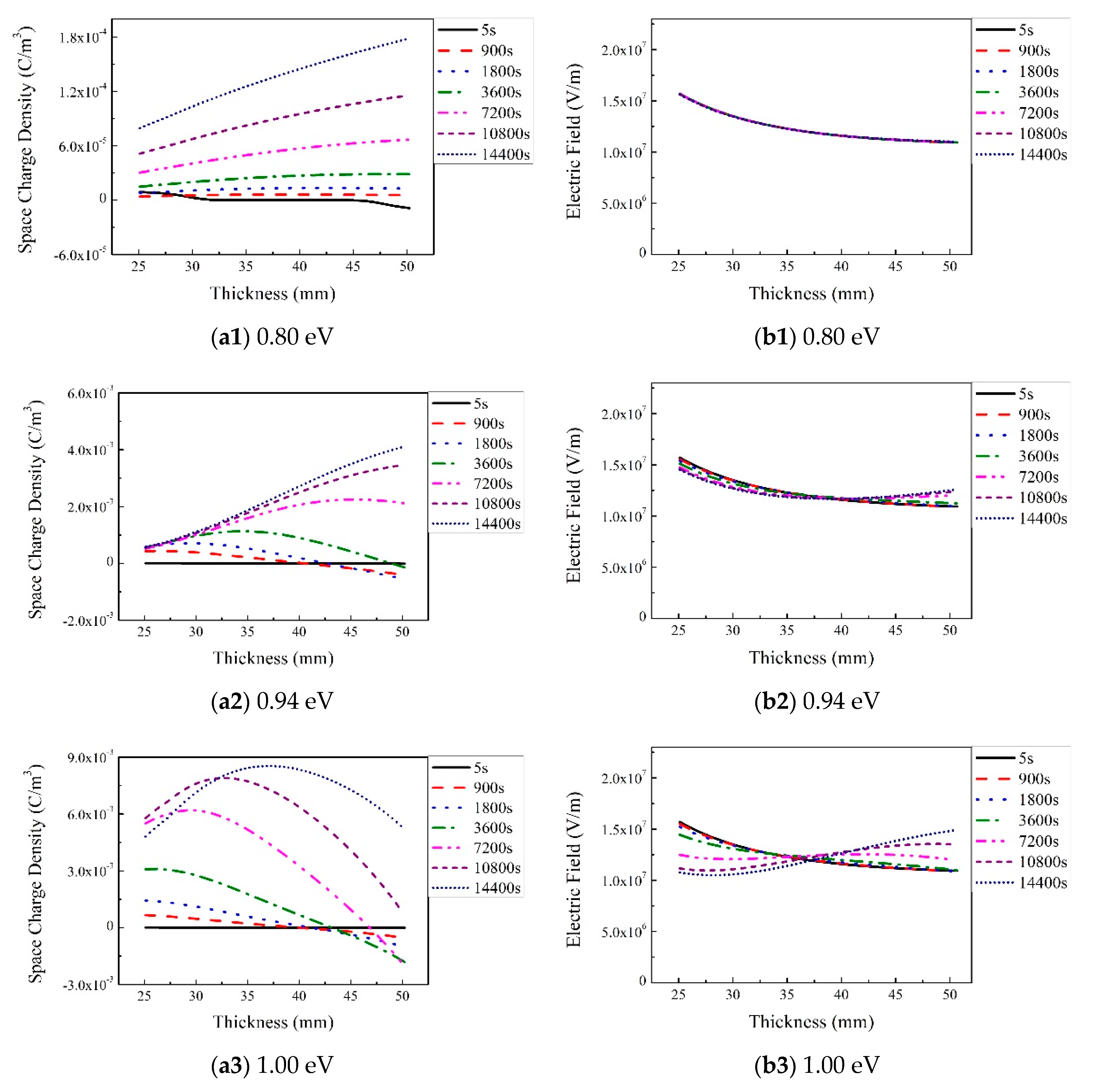
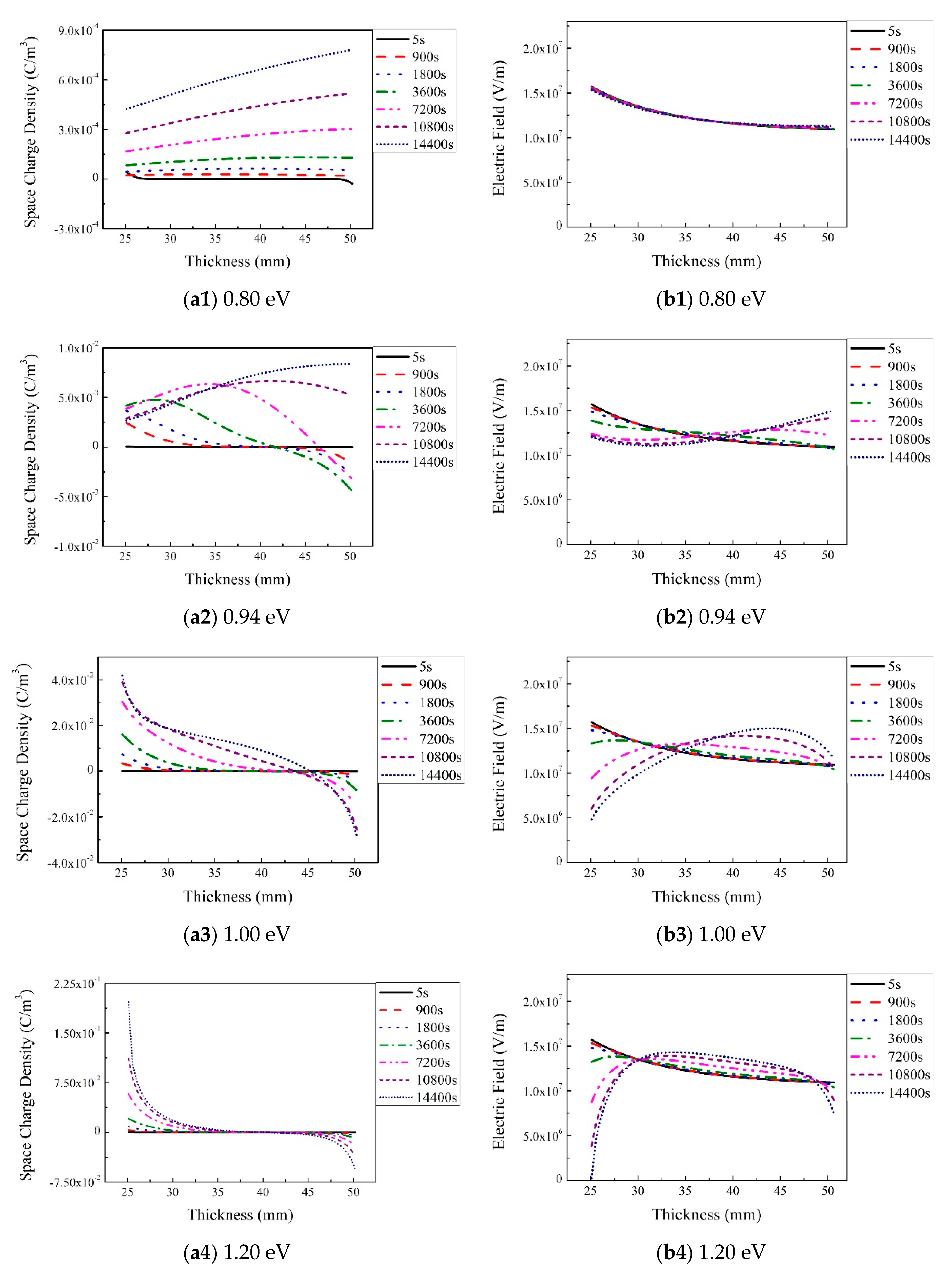
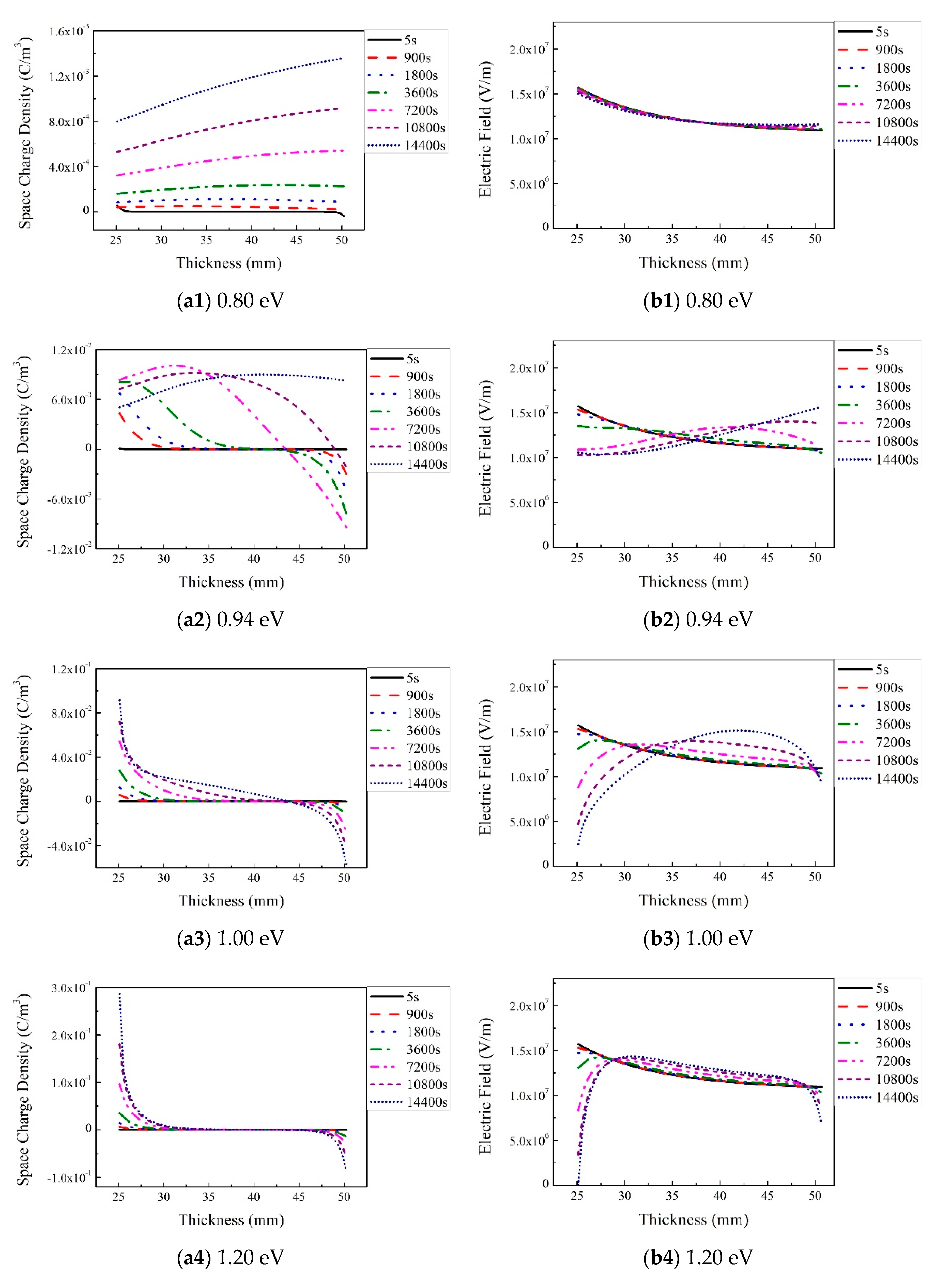
Figure 2, Figure 3, Figure 4 and Figure 5 show the space charge and electric field distribution in the cable insulation with the conductor carrying the rated load current of 1800 A and under the rated voltage 320 kV. The temperature distribution will be shown late in the following part. The trap density is 10 × 1019, 80 × 1019, 200 × 1019 and 1000 × 1019 m−3 and different trap depths (0.80, 0.94, 1.00, 1.20 eV) are selected for each trap density. The simulation duration is up to 14,400 s (4 h) after the voltage and load applied. Just as the simulation started for about 5 s in each Figure, nearly no space charge accumulates in the insulation and the electric field is very similar to the Laplace field.
Figure 2(a1–a4) show the evolution of the space charge and electric field distribution over time in the insulation with four different trap depths when the trap density is set to 10 × 1019 m−3: In Figure 2(a1), fewer space charges (less than 2 × 10⁻⁴ C/m3) of the same polarity as inner conductor are injected when the trap depth is 0.80 eV. Then, the positive charge injected from the inner conductor gradually spreads throughout the insulation over time. The charge density becomes larger in the outside than the inside insulation, called the space charge accumulation reversing. At 14,400 s, a positive charge of 1.8 × 10⁻⁴ C/m3 accumulated near the outer side, and a positive charge of 0.8 × 10⁻⁴ C/m3 accumulated near the inner side. Electron injection from the insulation outer shield can be omitted. With an increase in the trap depth, more space charges accumulate in the bulk insulation as shown in Figure 2(a2–a4). The positive and negative charge density reaches about 5 × 10⁻² C/m3 and 1 × 10⁻² C/m3 at 14,400 s separately around the inside and outside insulation when the trap depth is 1.2 eV. In addition, it shows that bipolar charge accumulation becomes increasingly significant with increasing trap depth. The positive charges around the conductor migrate faster and deeper into the insulation than the negative charges.
The electric field distributions are shown in Figure 2(b1–b4). The electric field has almost no change and keeps similar to Laplace electric field and varying with 1/r during 14,400 s when the trap depth is 0.80 eV. This is because the space charge density is too small to affect the electric field distribution as shown in Figure 21(a1). With an increase in the trap depth, electric field distortion induced by space charges becomes more and more severe. The electric field distribution shows inversion behavior for the trap depth 1 eV after 10,800 s, which shows that the inner and outer electric field is about 12 and 14 kV/mm at 14,400 s, respectively. This behavior agrees well with the space charge distribution changes with trap depth. This is because that the accumulated positive space charge around the conductor will increase the electric field in the outside insulation and decrease it in the inside insulation. The electric field distribution and evolution is much complex for the trap depth 1.2 eV. It shows that the electric field inside the insulation is continuously pulled down to about 4 kV/mm and the outside electric field is raised to 12 kV/mm at 14,400 s. Although the electric field is reversed, the highest electric field appears at about 42 mm in the middle of the insulation. The electric field distribution and evolution result from a remarkable amount of positive and negative charge accumulation and different transport behavior in the inside and outside insulation.
Figure 3 shows the evolution of the space charge and electric field distribution over time in the insulation at four different trap depths for the trap density 80 × 1019 m−3. In Figure 3(a1), positive charge of 7.5 × 10⁻⁴ C/m3 and 4 × 10⁻⁴ C/m3 are accumulated around the outside and the inside insulation separately after 14,400 s for the trap depth of 0.8 eV. Correspondingly, the electric field shows almost no change during 14,400 s and keeps a capacitive distribution as shown in Figure 3(b1). When the trap depth is 0.94 eV, both electrons and holes accumulate around the inside and outside insulation, respectively, after 900 s as shown in Figure 3(a2). The positive charge density and migration distance injected from the inner semiconductive shield are larger. At 10,800 and 14,400 s, the space charge accumulation reverses and positive charges become dominant. At 14,400 s, the positive charge density is 8 × 10⁻³ C/m3 and 2.5 × 10⁻³ C/m3 in the outside and inside insulation, respectively. Accordingly, the electric field distribution reverses as shown in Figure 3(b2), which shows that the electric field decreases in the inside of the insulation and rises in the outside insulation over time and reverses after 7200 s. For the trap depth of 1 eV, both positive charges and negative charges accumulate and migrate to the middle of the insulation over time. Positive charges dominate the charge accumulation and transport process. The electric field distribution gradually reverses and shows a maximum around 45 mm in the insulation at 14,400 s, while the electric field in the inside insulation drops to about 5 kV/mm. For the trap depth of 1.20 eV, more homopolar charges accumulate around the inner and outer insulation over time as shown in Figure 3(a4), but the charges migrate much more slowly compared with that for the trap depth of 1.0 eV. At 14,400 s, the positive and negative charge densities reach 0.2 C/m3 and 0.06 C/m3 in the inside and outside insulation, respectively. The electric field in the inside and outside insulation continuously drop over time and the electric field in the middle of the insulation slightly increases. At 14,400 s, the electric field around the inner semiconductive shield is pulled down to about zero.
Figure 4 and Figure 5 show the evolution of the space charge and electric field distribution in the insulation for different trap depths over time when the trap density is 200 × 1019 m−3 and 1000 × 1019 m−3, respectively. With an increase in the trap depth, space charge accumulation and bipolar charge injection become more and more significant, but the mitigation velocity decreases and the space charges accumulate is closer to the inner and outer semiconductive shield. Much fewer space charges accumulate in the bulk insulation. As a result, the electric field in the insulation around the conductor is pulled to about zero for the trap depth of 1.20 eV at 14,400 s. The electric field becomes more uniform and shows a capacitive distribution in case of no space charge accumulation. The electric field distribution reverses when the trap depth is 0.94 eV in Figure 4. The electric field reaches maximum values at about 45 mm when the trap depth is 1.00 eV in Figure 4 and 0.94 eV in Figure 5.

3.2. Effects of Trap Density on Space Charge and Electric Field Evolution

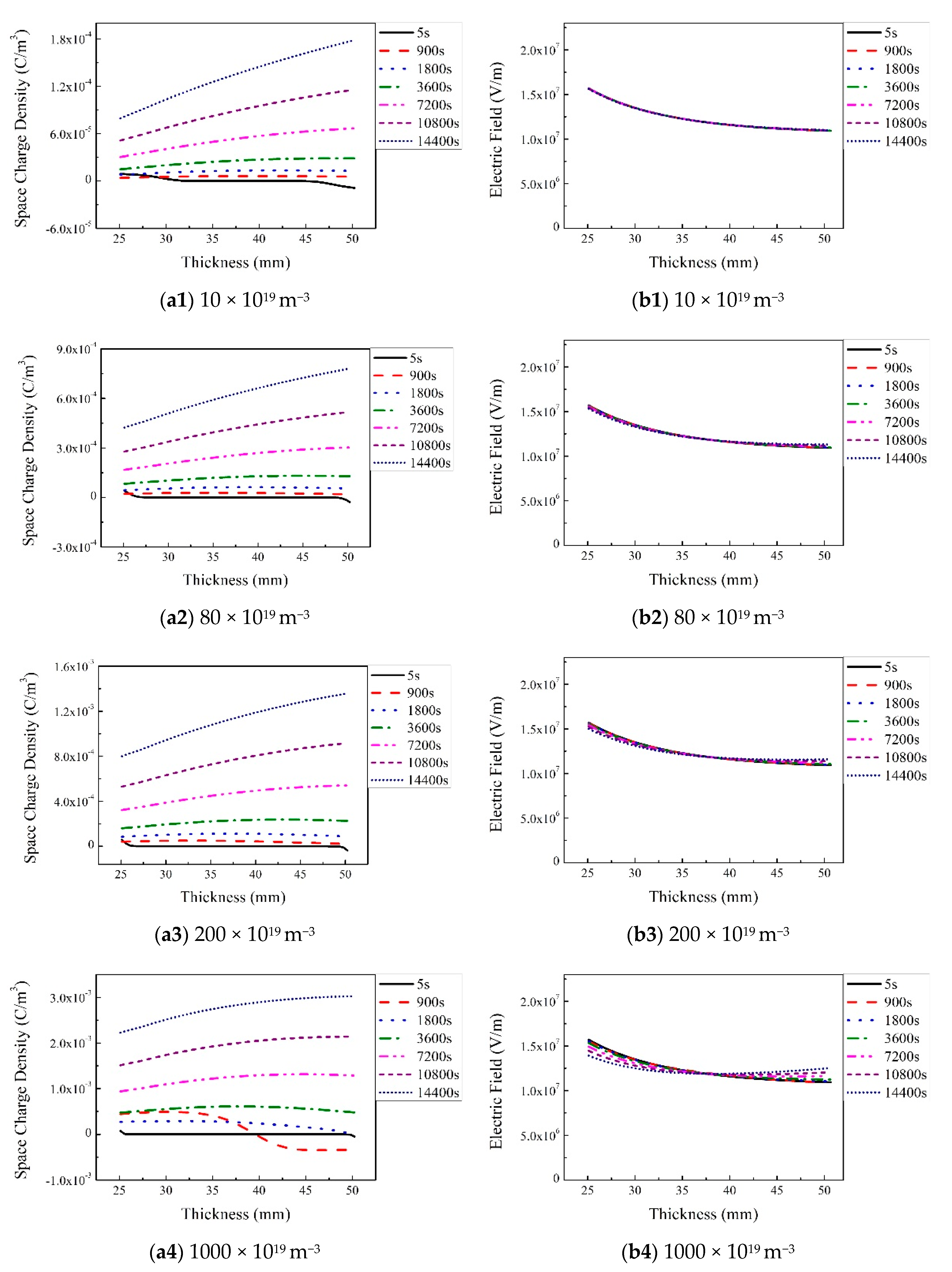
Figure 6, Figure 7 and Figure 8 show the space charge and electric field distributions for the trap depth of 0.80, 0.94 and 1.20 eV with the trap density varying from 10 × 1019 m−3 to 1000 × 1019 m−3. When the trap depth is 0.80 eV, very few space charges accumulate in the bulk insulation and the electric field is similar to the capacitive electric field distribution. The maximum space charge density is around 10−3 C/m3. When the trap depth is 0.94 eV, more and more space charges accumulate and the electric field distribution reverses gradually over time in the bulk insulation with the increase in trap density. In contrast, for the trap depth of 1.2 eV, space charge accumulation decreases and the electric field distribution becomes more and more uniform in the bulk insulation with the increasing trap density. However, space charge accumulation around the electrode interface area becomes significant with increasing trap density for the trap level of 1.20 eV.
In contrast to the phenomenon that space charge accumulation becomes more remarkable with an increase in the trap depth or trap density in 320 kV HVDC cable, it has been reported in many researches that space charge accumulation can be effectively suppressed with increasing trap depth or density for plate samples [15,20,21,22,23,24]. This means that space charge behavior in cylindric cable is significantly different from that in the plate samples and much more complex. In addition, in the constant-temperature flat samples, the increase in the trap density has a significantly greater suppression effect on the space charge than the trap depth. However, in the cable insulation under the electrothermal coupling field, the increase in the trap depth has a significantly greater effect on space charge suppression than the increase in trap density. In a plate sample with constant temperature, the applied electric field is high and the temperature is relatively low. Even if the Poole–Frenkel effect is considered, it is still relatively difficult for space charges to escape from the traps. To pull down the electric field at the conductor–insulation interface and then suppress charge injection from the conductor, a large number of space charges are required to be accumulated around the interface. In this case, the key to suppress space charge accumulation is to increase the trap density at the interface. Thus, the increase in trap density is more effective to suppress the space charges. In the cable sample under the electrothermal coupling field, the temperature around the inner conductor is higher and the applied electric field is lower, so the interface electric field can be pulled down with less trapped charges at the interface. However, due to the high temperature, it is relatively easy for a trapped charge to escape from the traps. In this case, the key to restrain space charge is to ensure that the trapped charge around the interface is difficult to escape. Therefore, increasing the trap depth is more effective. In short, for space charge suppression, increasing trap density is more effective at low temperatures and high electric field, while increasing the trap depth is more effective at high temperature and low field. Of course, increasing both the trap depth and trapping density will bring very excellent space charge suppression ability in both the plate samples under constant temperature and cylindrical HVDC cables under the electrothermal coupled field.

3.3. Effects of Load Current on Space Charge and Electric Field Evolution

Figure 9 shows the thermal field evolution of the cable in 14,400 s (4 h) with load currents of 0, 1800, 2100, and 2600 A, separately. Correspondingly, the inner conductor temperatures were 30, 60, 70, and 90 °C and the temperature difference between the inside and outside of the insulation was about 0, 20, 25, and 40 °C, respectively.
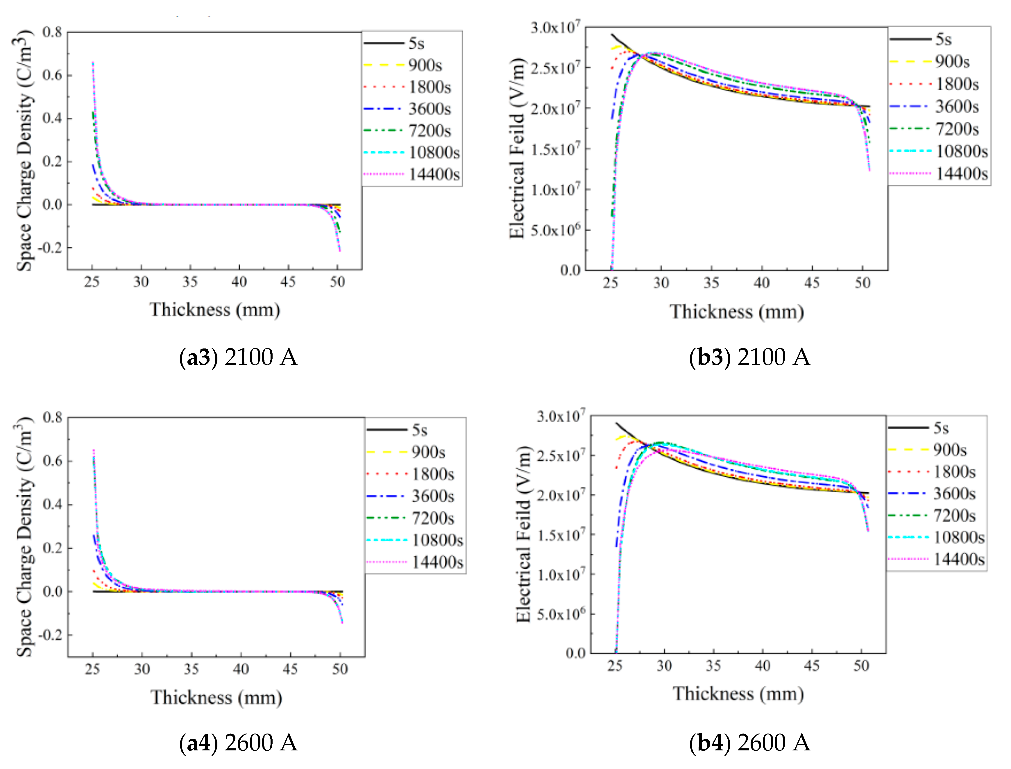
We simulated the space charge and electric field distribution for the case when the trap density was 80 × 1019 m−3 and the trap depth was 0.94 eV (typical values for LDPE), and the case when the trap density is 1000 × 1019 m−3 and the trap depth is 1.20 eV (modified insulation materials with deeper traps and larger trap density, such as many nanocomposite dielectrics) with a different load current and temperature gradients as shown in Figure 10 and Figure 11.
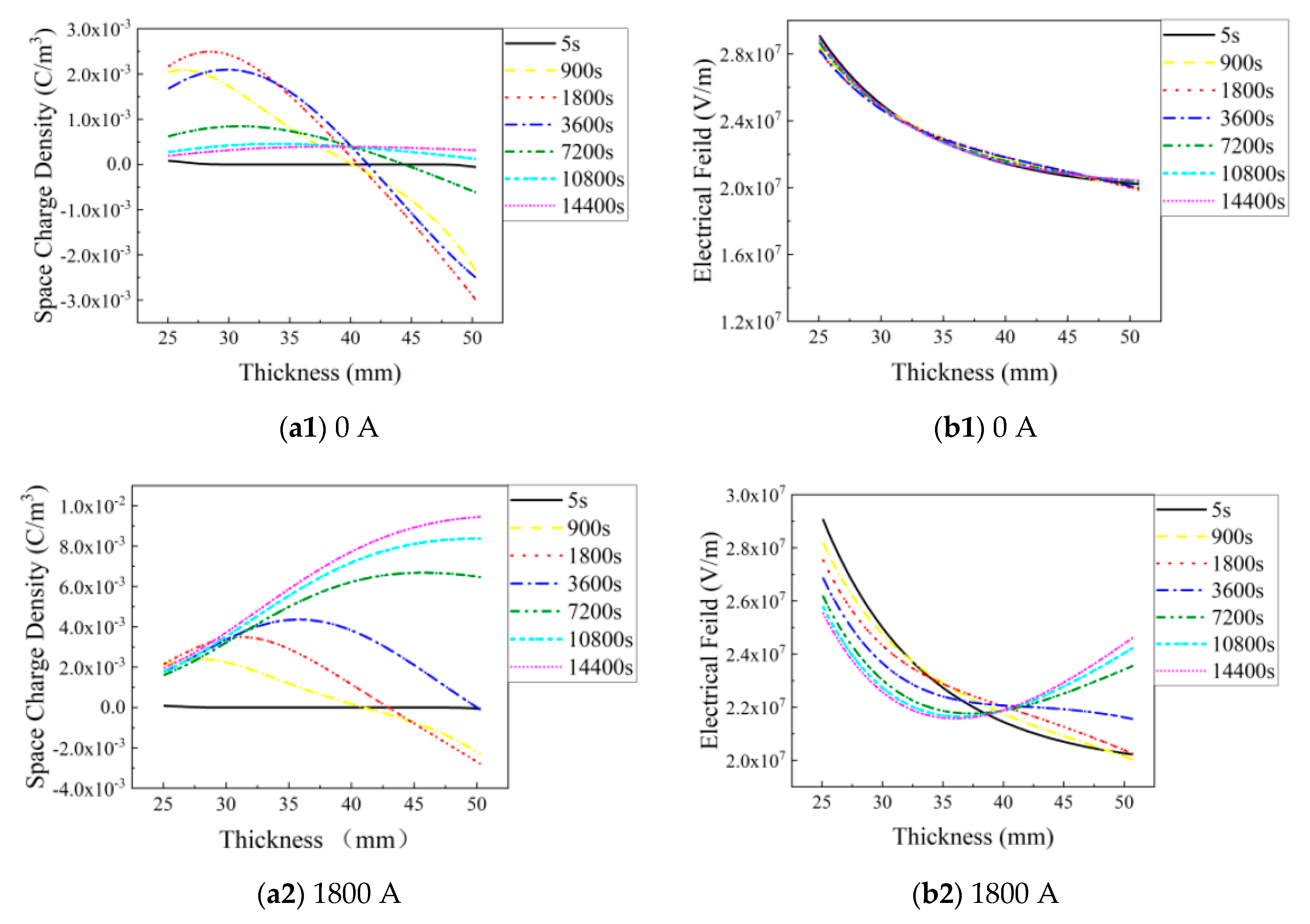
Figure 10 shows the space charge and electric field distribution for the trap depth of 0.94 eV and trap density of 80 × 1019 m−3 with the load current varying from 0 to 2600 A. For the load current of 0 A, very few space charges accumulate in the bulk insulation and the electric field keeps a capacitive distribution. When the load current is 1800, 2100, and 2600 A separately, the space charge accumulation becomes more and more remarkable and the electrical field distribution reverses seriously over time with increasing the load current.
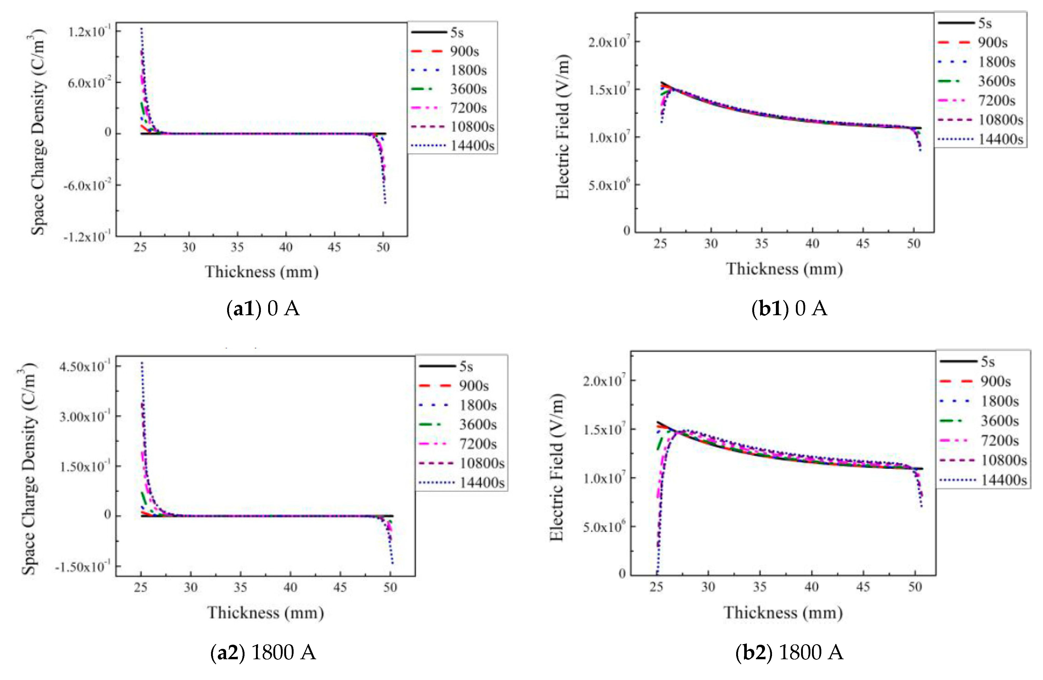
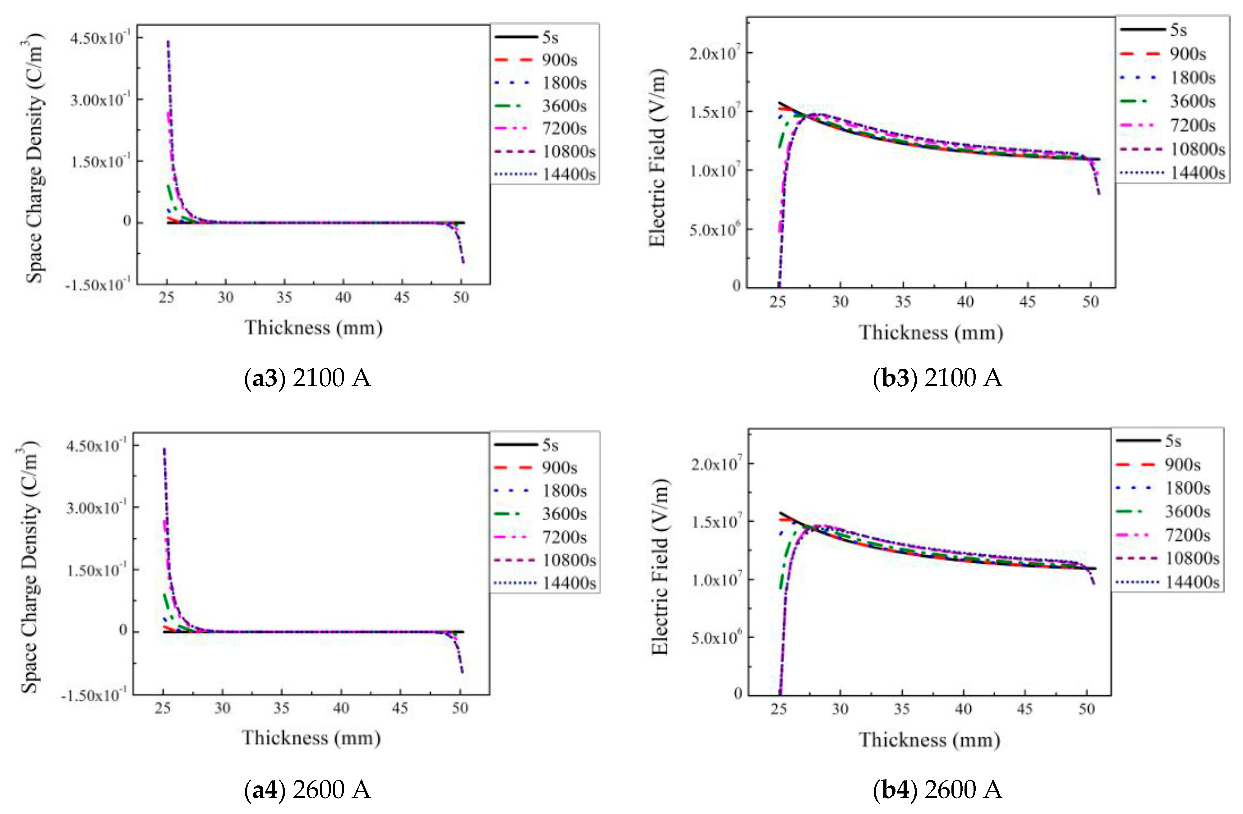
Figure 11 shows the space charge and electric field distribution for the trap depth of 1.20 eV and trap density of 1000 × 1019 m−3 with the load current varying from 0 A to 2600 A. Compared with Figure 10, the space charge has much less migration distance and most space charges accumulate around the inner and outer insulation interface areas. The overall space charges increase with increasing load current and have a maximum of about 0.45 C/m3. Accordingly, the electric field keeps a capacitive distribution in the bulk insulation and is pulled down around the insulation surface. Therefore, the increase in trap depth and trap density shows excellent bulk space charge suppression behavior. However, the effect of trapped charges with large density at the conductor–dielectric interface on the dielectric properties of the HVDC cable insulation should be reassessed especially under polarity reversal conditions.

3.4. Effects of Applied Voltage on Space Charge and Electric Field Evolution

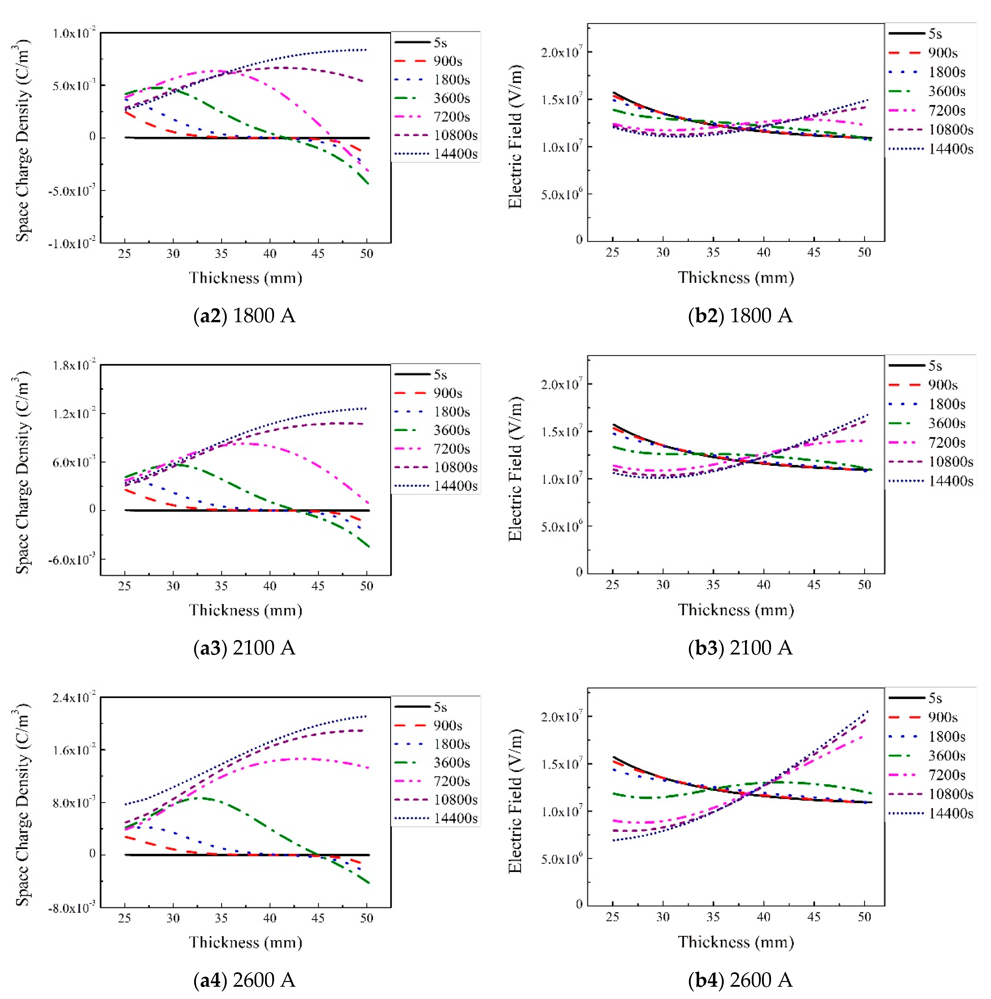
Figure 12 shows the space charge and electric field distributions when the trap density is 80 × 1019 m−3 and the trap depth is 0.94 eV with different load current and temperature gradients under 592 kV. The voltage 592 kV is the DC test voltage for 320 kV HVDC cables. Figure 12(a1,b1) show a few charge injection and nearly capacitive electrical field distribution. In Figure 12(a2–a4) and Figure 12(b2–b4), both positive and negative charges are initially injected in the insulation. Over time, more and more positive charges are injected from the inner conductor and move toward the outer insulation with increasing load current, causing serious electric field reversion. Both space charge accumulation and electric field distortion are more serious than that at 320 kV.
Figure 13 shows the space charge and electric field distribution when the trap depth is 1.20 eV and the trap density is 1000 × 1019 m−3 with different load current and temperature gradients under 592 kV. Compared with Figure 12, the space charge has much less migration distance and most space charges accumulate around the inner and outer insulation interface areas. Accordingly, the electric field almost keeps a capacitive distribution in the bulk insulation and is significantly pulled down around the insulation surface. Therefore, the increase in trap depth and trap density has remarkably suppressed space charge accumulation and improved the electric field distribution in the bulk insulation.
Space charge behavior in film and plate samples has shown that the increase in trap densities or depth by nanofillers or grafting polar groups in polyethylene can significantly suppress space charge accumulation [25,26,27,28]. However, the dependence of space charge and electric field evolution on trap characteristics is much more complex in the HVDC cable with cylindrical structure under electrothermal stress, especially under a temperature gradient as shown above. In contrast to plate samples, increasing trap density or trap depth can result in more serious space charge accumulation and electric field distortion in HVDC cables. Proper trap characteristics can contribute to space charge accumulation in HVDC cables with a low load current but may increase space charge accumulation with increasing load current or temperature gradient. In other words, the effect of trap characteristics on space charge accumulation and electric field distribution in plate samples is not equivalent to that in actual HVDC cables. We should bear in mind the different effects when developing and evaluating new HVDC insulation materials by including nanofillers or grafting proper groups.
The microscopic mechanism and physical nature behind how the trap characteristic regulates space charge behavior and its evolution in HVDC cables under electrothermal stress is important to develop new HVDC insulation materials and assess the insulation status during long-term operation. Essentially, the space charge accumulation or suppression in the insulation materials depends on the balance between the conductor injection current Jin and the bulk conduction current Jb, both of which are regulated by trap characteristics. A trap-regulated space charge suppression model (TR-SCS) has been proposed for plate samples to reveal how the trap characteristics regulate and control the space charge suppression and charge transport in our previously published research [15]. The TR-SCS model also applies to the situation in HVDC cables under electro–thermal stress.
In the case of Jin ≤ Jb or the extremely high bulk conductivity, the charges injected from conductor can be drawn out from the sample. As a result, the bulk space charge accumulation is suppressed. This is the case when the trap depth is 0.80 eV and the trap density is 10 × 1019 m−3.
In the case of Jin > Jb, the bulk conductivity is low, thus the charge injection rate is so large compared with the rate of charge drawn out that some injected charges exist in the sample. The trap characteristics determine the number, location and distribution of the space charges. The relatively low trap density and/or low trap depth (for example, the case where the trap depth is 0.95 eV) cause the relatively low bulk conductivity, which results in that the charge injection rate is just a little larger than the rate of the charge drawn out. As a result, the charges injected from the cable conductor will slowly migrate to the dielectrics inside and accumulate in the bulk. This is due to that the injected charges will keep largely free for the low trap density and/or low trap depth, causing a lower trapping rate and/or faster detrapping rate. In contrast, very high trap density and/or high trap depth (when the trap depth is 1.2 eV and trap density is 1000 × 1019 m−3) cause the very low bulk conductivity and carrier mobility. Then, many injected charges immediately are trapped near the interface between conductor and insulation which forms a thin layer of trapped charges and prevents the charge from moving inside the dielectrics. In this case, the process of charge trapping is much stronger than the process of charge detrapping. The trapped charge layer produces an opposite electric field that decreases the electric field of interface and raises the charge injection potential. This causes the prominent decrease in injection current and reaches a lower-level balance between the injection current and the bulk conduction current at last. Therefore, fewer charges can move into the inner insulation and accumulate in the sample. As a result, increasing the trap depth and density is an effective way to suppress bulk space charge and decrease bulk conductivity.

4. Conclusions

We studied the impact of trap density and depth on the space charge and electric field evolution behavior under different load current and voltages by combined numerical bipolar charge transport (BCT) and thermal field simulation. The following conclusions can be drawn.
(1)
The effect of trapping characteristics on space charge and electric field evolution in HVDC cable insulation under electrothermal stress is obviously different from that in the plate samples with constant temperature, and more complex especially when the current load varies.
(2)
Enhancing bulk conduction current by decreasing trap depth and trap density can effectively suppress the accumulation of bulk space charge and conductor–insulation interface space charge. However, this will increase the leaking current and power loss.
(3)
Simultaneously increasing the trap density and depth can remarkably suppress bulk space charge accumulation and electric field distortion in the cable insulation under the electrothermal coupling field. However, the effect of trapped charges with large density at the conductor–dielectric interface on the dielectric properties of the HVDC cable insulation should be reassessed especially under polarity reversal conditions.

Author Contributions

F.T. conceived the presented idea and analyzed the research data. The article is originally written by F.T. and revised by author S.Z. and C.H. All authors have read and agreed to the published version of the manuscript.

Funding

This research was funded by Basic Scientific Research Program, grant number 2019JBM056.

Institutional Review Board Statement

Not applicable.

Informed Consent Statement

Not applicable.

Data Availability Statement

The data are not publicly available.

Acknowledgments

This work was supported by the Basic Scientific Research Program under Contract No. 2019JBM056.

Conflicts of Interest

The authors declare no conflict of interest.

References

  1. Du, B.X.; Li, Z.; Yang, Z.; Jin, L. Application and research progress of HVDC XLPE cables. High Volt. Eng. 2017, 43, 344–354. [Google Scholar]
  2. Mazzanti, G.; Marzinotto, M. Extruded Cables for High Voltage Direct Current Transmission: Advances in Research and Development; John Wiley & Sons: Hoboken, NJ, USA, 2013. [Google Scholar]
  3. Hao, Y.P.; Chen, Y.; Yang, L.; Qiu, W.H.; Fu, M.; Hou, S. Coupled Simulation on Electro-thermal-fluid Multiple Physical Fields of HVDC Submarine Cable. High Volt. Eng. 2017, 43, 3534–3542. [Google Scholar]
  4. He, J.L.; Dang, B.; Zhou, Y.; Hu, J. Reviews on Research Progress and Key Technology in Extruded Cables for HVDC Trans-mission. High Volt. Eng. 2015, 41, 1417–1429. [Google Scholar]
  5. Mazzanti, G.; Marzinotto, M. Fundamentals of HVDC Cable Transmission. In Extruded Cables for High-Voltage Direct-Current Transmission: Advances in Research and Development; IEEE: New York, NY, USA, 2013; Volume 43, pp. 11–40. [Google Scholar]
  6. Li, Z.H.; Liu, L.L.; Zheng, H.; Liang, S.T. Simulation on the Influence Factors of Electric Field Distribution in HVDC Cable. Proc. CSEE 2016, 36. [Google Scholar]
  7. Yan, Y.X.; Fang, X.L.; Zhang, W.G.; Zhao, J.; Chen, C. Cable Section and Laying of Xiamen ±320 kV Flexible DC Cable Transmission Project. High Volt. Eng. 2015, 41, 1147–1153. [Google Scholar]
  8. Doedens, E.; Jarvid, E.M.; Guffond, R.; Serdyuk, Y.V. Space Charge Accumulation at Material Interfaces in HVDC Cable Insulation Part I—Experimental Study and Charge Injection Hypothesis. Energies 2020, 13, 2005. [Google Scholar] [CrossRef] [Green Version]
  9. Doedens, E.; Jarvid, E.M.; Guffond, R.; Serdyuk, Y.V. Space Charge Accumulation at Material Interfaces in HVDC Cable Insulation Part II—Simulations of Charge Transport. Energies 2020, 13, 1750. [Google Scholar] [CrossRef] [Green Version]
  10. Rizzo, G.; Romano, P.; Imburgia, A.; Viola, F.; Ala, G. The Effect of the Axial Heat Transfer on Space Charge Accumulation Phenomena in HVDC Cables. Energies 2020, 13, 4827. [Google Scholar] [CrossRef]
  11. Zhan, Y.; Chen, G.; Hao, M.; Pu, L.; Zhao, X.; Wang, S.; Liu, J. Space Charge Measurement and Modelling in Cross-Linked Polyethylene. Energies 2020, 13, 1906. [Google Scholar] [CrossRef]
  12. Zhou, Y.; Wang, W.; Guo, T. Space Charge Accumulation Characteristics in HVDC Cable under Temperature Gradient. Energies 2020, 13, 5571. [Google Scholar] [CrossRef]
  13. Kim, S.; Lee, B. Numerical Analysis of Space Charge Behavior and Transient Electric Field under Polarity Reversal of HVDC Extruded Cable. Energies 2020, 13, 2845. [Google Scholar] [CrossRef]
  14. Du, B.X.; Han, C.; Li, J.; Li, Z. Temperature-dependent DC conductivity and space charge distribution of XLPE/GO nanocom-posites for HVDC cable insulation. IEEE Trans. Dielectr. Electr. Insul. 2020, 27, 418–426. [Google Scholar] [CrossRef]
  15. Tian, F.Q.; Hou, C.Y. A trap regulated space charge suppression model for LDPE based nanocomposites by simulation and experiment. IEEE Trans. Dielectr. Electr. Insul. 2018, 25, 2169–2177. [Google Scholar] [CrossRef]
  16. Mauseth, F.; Haugdal, H. Electric field simulations of high voltage DC extruded cable systems. IEEE Electr. Insul. Mag. 2017, 33, 16–21. [Google Scholar] [CrossRef] [Green Version]
  17. Che, H. Simulation on Dynamic Space Charge Behaviour in LDPE. Master Thesis, Harbin University of Science and Technology, Harbin, China, 2014. [Google Scholar]
  18. Wu, J. Charge Transport Investigation in Low-Density Polyethylene/Silica Nanocomposite Based on Experiment and Numerical Simulation. Ph.D. Thesis, Shanghai Jiao Tong University, Shanghai, China, 2012. [Google Scholar]
  19. Xia, J. Numerical Simulation and Experimental Study on Space Charge Interface Injection and Bulk Tranportion in LDPE. Ph.D. Thesis, Tongji University, Shanghai, China, 2010. [Google Scholar]
  20. Tian, F.; Zhang, J.; Peng, X.; Hou, C. Interface trapping effects on the charge transport characteristics of LDPE/ZnO nano-composites. IEEE Trans. Dielectr. Electr. Insul. 2017, 24, 1888–1895. [Google Scholar] [CrossRef]
  21. Tian, F.; Yao, J.; Li, P.; Wang, Y.; Wu, M.; Lei, Q. Stepwise electric field induced charging current and its correlation with space charge formation in LDPE/ZnO nanocomposite. IEEE Trans. Dielectr. Electr. Insul. 2015, 22, 1232–1239. [Google Scholar] [CrossRef]
  22. Tian, F.; Lei, Q.; Wang, X.; Wang, Y. Effect of Deep Trapping States on Space Charge Suppression in Polyethylene/ZnO Nanocomposite. Appl. Phys. Lett. 2011, 99, 142903. [Google Scholar] [CrossRef]
  23. Tian, F.; Lei, Q.; Wang, X.; Wang, Y. Investigation of electrical properties of LDPE/ZnO nanocomposite dielectrics. IEEE Trans. Dielectr. Electr. Insul. 2012, 19, 763–769. [Google Scholar] [CrossRef]
  24. Zhou, Y.; Yuan, C.; Li, C.; Meng, P.; Hu, J.; Li, Q.; He, J. Temperature dependent electrical properties of thermoplastic polypropylene nanocomposites for HVDC cable insulation. IEEE Trans. Dielectr. Electr. Insul. 2019, 26, 1596–1604. [Google Scholar] [CrossRef]
  25. Paramane, A.; Chen, X.; Dai, C.; Guan, H.; Yu, L.; Tanaka, Y. Electrical insulation performance of cross-linked polyeth-ylene/MgO nanocomposite material for ±320 kV high-voltage direct-current cables. Polym. Compos. 2020, 41, 1936–1949. [Google Scholar] [CrossRef]
  26. Liang, Y.; Liu, L.; Zhang, W.; Weng, L.; Li, C. Preparation and electrical properties of 4-acetoxystyrene grafted polypropylene for HVDC cable insulation. J. Mater. Sci. Mater. Electron. 2020, 31, 3890–3898. [Google Scholar] [CrossRef]
  27. Zha, J.W.; Qin, Q.Q.; Dang, Z.M. Effect of multi-dimensional zinc oxide on electrical properties of polypropylene nanocom-posites for HVDC cables. IEEE Trans. Dielectr. Electr. Insul. 2019, 26, 868–875. [Google Scholar] [CrossRef]
  28. Ashish, P.; Sathish, K.; Hafizi, A.M.; Afendi, M.P.M. Space Charge and Conductivity Measurement of XLPE Nanocomposites for HVDC Insulation—Permittivity as a Nanofiller Selection Parameter. IET Sci. Meas. Technol. 2018, 12, 1058–1065. [Google Scholar]
Figure 1. Geometry of the 320 kV high voltage–direct current (HVDC) cable.
Energies 14 01313 g001
Figure 2. Simulation results of space charge distribution (a1a4) and electric field distribution (b1b4) in 320 kV HVDC cable insulation when the trap depth varies from 0.80 to 1.20 eV with the trap density of 10 × 1019 m−3 and load current of 1800 A.
Energies 14 01313 g002aEnergies 14 01313 g002b
Figure 3. Simulation results of space charge distribution (a1a4) and electric field distribution (b1b4) in 320 kV HVDC cable insulation when the trap depth varies from 0.80 to 1.20 eV with the trap density of 80 × 1019 m−3 and load current of 1800 A.
Energies 14 01313 g003
Figure 4. Simulation results of space charge distribution (a1a4) and electric field distribution (b1b4) in 320 kV HVDC cable insulation when the trap depth varies from 0.8 to 1.20 eV with the trap density of 200 × 1019 m−3 and load current of 1800 A.
Energies 14 01313 g004
Figure 5. Simulation results of space charge distribution (a1a4) and electric field distribution (b1–b4) in 320 kV HVDC cable insulation when the trap depth varies from 0.8 to 1.20 eV with the trap density of 1000 × 1019 m−3 and load current of 1800 A.
Energies 14 01313 g005
Figure 6. Simulation results of space charge distribution (a1a4) and electric field distribution (b1b4) in 320 kV HVDC cable insulation when the trap density varies from 10 × 1019 m−3 to 1000 × 1019 m−3 with the trap depth of 0.80 eV and load current of 1800 A.
Energies 14 01313 g006
Figure 7. Simulation results of space charge distribution (a1a4) and electric field distribution (b1b4) in 320 kV HVDC cable insulation when the trap density varies from 10 × 1019 m−3 to 1000 × 1019 m−3 with the trap depth of 0.94 eV and load current of 1800 A.
Energies 14 01313 g007
Figure 8. Simulation results of space charge distribution (a1a4) and electric field distribution (b1b4) in 320 kV HVDC cable insulation when the trap density varies from 10 × 1019 m−3 to 1000 × 1019 m−3 with the trap depth of 1.20 eV and load current of 1800 A.
Energies 14 01313 g008
Figure 9. Temperature distribution of 320 kV HVDC cable with load currents of 0, 1800, 2100 and 2600 A.
Energies 14 01313 g009
Figure 10. Simulation results of space charge distribution(a1a4) and electric field distribution(b1b4) in HVDC insulation when the trap density is 80 × 1019 m−3, trap depth is 0.94 eV with load current varying from 0 A to 2600 A under 320 kV.
Energies 14 01313 g010aEnergies 14 01313 g010b
Figure 11. Simulation results of space charge distribution(a1a4) and electric field distribution(b1b4) in HVDC insulation when the trap density is 1000 × 1019 m−3, trap depth is 1.20 eV with load current varying from 0 to 2600 A under 320 kV.
Energies 14 01313 g011aEnergies 14 01313 g011b
Figure 12. Simulation results of space charge distribution (a1a4) and electric field distribution (b1b4) in HVDC insulation when the trap density is 80 × 1019 m−3, trap depth is 0.94 eV with load current varying from 0 to 2600 A under 592 kV.
Energies 14 01313 g012aEnergies 14 01313 g012b
Figure 13. Simulation results of space charge distribution (a1a4) and electric field distribution (b1b4) in HVDC insulation when the trap density is 1000 × 1019 m−3, the trap depth is 1.20 eV with a load current varying from 0 to 2600 A under 592 kV.
Energies 14 01313 g013aEnergies 14 01313 g013b
Table 1. Size and the material parameter of the 320 kV HVDC cable.
ConstructionThickness or Radius
(mm)
Density
(kg/mm3)
Coefficient of Heat Conductivity
(W/(m·K))
Specific Heat Capacity (J/(kg·K))
Conductor258.89 × 10−6-390
Conductor shield21.12 × 10−60.252700
Insulation261.20 × 10−60.202300
Insulation shield11.12 × 10−60.252700
Water-blocking tape21.15 × 10−60.232000
Metallic sheath2.82.70 × 10−6156947
Polyethylene sheath50.95 × 10−60.302302
Soil2002.60 × 10−60.201500
Table 2. Parameters for the bipolar charge transport (BCT) model.
Model ParameterNumerical ValueUnit
Electron injection barrier1.25eV
Hole injection barrier1.25eV
Electron jump barrier height0.45eV
Hole jump barrier height0.45eV
Jump distance between electronic shallow traps3 × 10−9m
Jump distance between shallow hole traps3 × 10−9m
Electron trapping coefficient0.1s−1
Hole trapping coefficient0.1s−1
Deep trap density of electron80 × 1019m−3
Deep trap density of hole80 × 1019m−3
Deep trap depth of electron0.94eV
Deep trap depth of hole0.94eV
Recombination coefficient S1, S2, S31 × 10−5m3·C−1·s−1
Recombination coefficient S00m3·C−1·s−1
Publisher’s Note: MDPI stays neutral with regard to jurisdictional claims in published maps and institutional affiliations.