Article

New Insights into Hydrothermal Fluid Circulation Affected by Regional Groundwater Flow in the Asal Rift, Republic of Djibouti

1
INRS-Institut National de la Recherche Scientifique, 490, Rue de la Couronne, Québec, QC G1K 9A9, Canada
2
BRGM, 3, Avenue Claude Guillemin, la CEDEX 02, 45062 Orléans, France
*
Author to whom correspondence should be addressed.
Energies 2021, 14(4), 1166; https://doi.org/10.3390/en14041166
Submission received: 20 January 2021 / Revised: 15 February 2021 / Accepted: 17 February 2021 / Published: 22 February 2021

Abstract

:
The Asal Rift hosts a lake located in a depression at 150 m below sea level, where recharge is influenced by regional groundwater flow interacting with the Ghoubbet Sea along the coast of Djibouti. This regional groundwater flow is believed to influence hydrothermal fluid circulation, which we aim to better understand in this study, having the objective of developing concepts for geothermal exploration in the area. To this end, magnetotelluric data acquired in the Asal Rift were processed and analyzed. 1D inversion models of electrical conductivity were interpolated for interpretation. These data were then used to build a 2D hydrogeological model, allowing multiphase flow and heat transfer simulations to be performed, considering the regional groundwater flow near the surface and the site topography, in order to confirm the preferred path of fluid flow. Geophysical data analysis indicates the presence of normal faults, notably the H fault, which may act as a conduit for the circulation of hydrothermal fluids and where the hanging wall can be a hydrogeological barrier within the hydrothermal system of the Asal Rift. The results from the 2D numerical flow and heat transfer modelling show the importance of groundwater flow responsible for thermal springs located at the periphery of Asal Lake. Reservoir temperature inferred by means of geothermometry ranging from 200 to 270 °C was shown to correspond to simulated temperature at potential reservoir depth. Moreover, simulated temperature between 600 and 1700 m depth is close to the temperature profile measured in the geothermal well Asal 6 of the area, with less than 20 °C difference. Simulations indicate that hydrothermal fluid circulation is likely influenced by the regional groundwater flow controlled by the topography and the major water bodies, the Ghoubbet Sea and Asal Lake, feeding buoyant fluids interacting with a deep magmatic source and where tectonic activity created normal faults offering a preferred path for fluid circulation.

1. Introduction

Extensive tectonic environments are known to host significant geothermal resources with large-scale fluid flows [1]. The Asal Rift is located in the central part of the Republic of Djibouti in the Afar depression, a tectonically active region where three major structures, the Great Rift Valley, the Red Sea, and the Gulf of Aden, are in extension and together form the Afar Triple [2,3], an emerged oceanic rift like that of Iceland. This region is a geological laboratory, where several scientific studies have been conducted to understand the processes and mechanisms related to the rifting phenomenon. The geological, geophysical, and geochemical studies carried out with French–Italian scientific collaboration between 1975 and 1988 guided the drilling of six deep geothermal exploration boreholes. A 3D geophysical model was built from passive seismic data [4] and indicated that the dip of normal faults far from the rift axis is about 50°–60° in the NE–SW direction, whereas normal faults close to the rift axis are sub-vertical. The tectonic activity of these faults and the volcanism of the area, including the last eruption of the Ardoukoba volcano in 1978, are sources of seismic activity and drivers of hydrothermal fluid circulation. The results of seismic tomography indicate that most of the seismic events are located in the first 3 km below the surface [4]. Nevertheless, seismicity within the Asal Rift does not seem to be related to vertical fault planes, but rather to the opening of the fractures through a pressure gradient caused by hot fluids rising under the rift [5]. This mechanism implies that the planes of normal faults begin to tilt away from the rift axis [4] and could act as natural conduits allowing hydrothermal fluid circulation.
Asal Lake, which is 150 m below sea level, is affected by saline groundwater originating from the Ghoubbet sea located 12 km southeastward [2,3]. The role of normal faults in groundwater circulation in the Asal Rift appears important, especially for the circulation of groundwater interacting with Asal Lake, the Ghoubbet Sea, and the deep hydrothermal circulation of hot fluids, which has not been studied with modern physical models that can reproduce multiphase flow and heat transfer mechanisms. The present study is based on this hypothesis, for which work was conducted to better understand the importance of normal faults in the circulation of groundwater and hydrothermal fluids. This study was conducted in the context of geothermal exploration to provide fundamental knowledge analyzing the role of faults and considering the impact of groundwater flow between the Ghoubbet Sea and the Asal Lake. The work aims to define which faults can act as conduits or barriers to groundwater flow within the Asal Rift. To achieve this goal, electrical resistivity data were analyzed to build a conceptual model of the rift, followed by quantitative multiphase and heat transfer modelling of the hydrothermal system in 2D.

2. Geodynamic and Hydrogeological Context

The westward propagation of the Gulf of Aden at a velocity of 30 mm/year gave rise to the emergence of the Asal Rift [2]. The opening of the Asal Rift segment dates from the Miocene and its geology is characterized by the abundance of volcanic rocks formed in an environment of extension and opening. This emerged rift segment is 15 km long and 14 km wide. The opening velocity is approximately 16 mm/year [
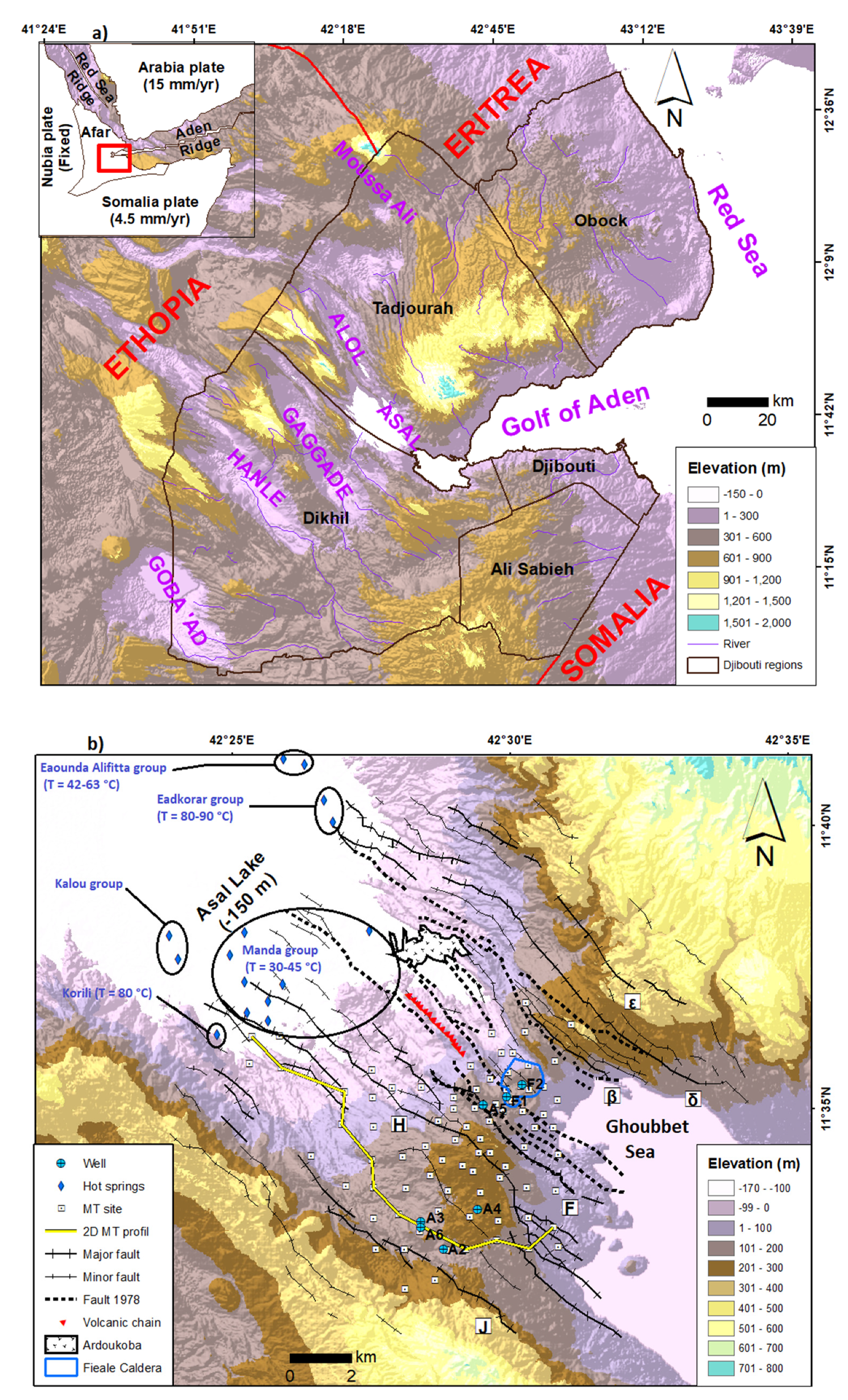
6] in the direction of N°45° E. The structure of this rift is characterized by a set of fracture networks and normal faults in the N130°E direction between Asal Lake and Ghoubbet Bay (Figure 1). Having a thin thickness and basaltic lavas at the surface in the form of basalt series, the land crust of the Asal Rift is considered transitional, i.e., an intermediate between the continental and nascent oceanic crust [4]. The first effusive event linked to the birth of the rift dates from 853,000 to 315,000 years ago [7]. Effusive magmatic activity continued in the northern part of the Asal Rift for 315,000 years and the southern part has been under seawater for 326,000 years, with the formation of hyaloclastites [7]. The activity of the central Fieale Caldera controlled the evolution of the rift between 326,000 and 100,000 years ago. Indeed, it allowed the injection of large volumes of basaltic lava into the interior floor that masked the previous faults [8]. Over the last 50,000 years, volcanic activity has decreased and the successive basaltic flow formations that make up Fieale Caldera have gradually been shifted by normal faults [7]. The modern rift structure began about 40,000 to 30,000 years ago with the development of the faults with outer margins H and δ [9]. From this period, the Fieale Caldera gradually extinguished and volcanic activity continued along the interior floor with small volcanic edifices and eruptive fissures [7]. With the most recent magmato-tectonic event dated in November 1978, two earthquakes of magnitude 5 and 5.3 were recorded in the Asal-Ghoubbet Rift and, following this event, 0.7 m of vertical subsidence and 2 m of horizontal extension in the direction N °40 E occurred in the rift [9]. A one-week eruption accompanied by basaltic fissures to the northwest of the rift gave rise in November 1978 to the axial volcanic chain and then to the eruption of the Ardoukoba volcano (Figure 1). At present, most of the rift deformation is concentrated in its north-eastern part and around the edifice of the Fieale Caldera [4,5,6].
Thermal springs, fumaroles, and the existence of alteration on the surface of the Asal Rift are indicators of volcanic activity and the presence of potential geothermal resources at depth. Hot springs are abundant around the Asal Lake, especially in the eastern part, with temperatures ranging from 30 to 90 °C (Figure 1). Between the Asal Lake and the Ghoubbet Sea, only fumaroles are observed at the surface because the hydrostatic level is below the topographic surface.
Chemical analyses of gases and determination of δD and δ18O water stable isotopes of steam condensate have been performed for some of these fumaroles [10,11]. The results allowed estimating the source temperature at a depth higher than 230 °C, and even than 300 °C, in the studied Asal Rift. The isotopic data from the steam condensate suggest the existence of primary steam (likely separated at high temperature) originating from a deep heavy brine in this area [11]. The existence of this primary steam is in good agreement with the presence of a dominant vapor zone in the conceptual geothermal model proposed by BRGM [10,11,12].
Owing to the high salinity of Asal Lake and according to geochemical analyses, about 90% of the recharge of Asal Lake is believed to be due to infiltration and evaporation of Ghoubbet seawater [3], depleted in sulfate because of CaSO4 precipitation [13]. From a geochemical study of water sampled from the rift thermal springs, the authors of [3] showed that the chemical and Sr isotope composition of these waters can be explained by variable seawater interaction with basaltic rocks at different temperatures and evaporation processes. Among thermal waters, those of the Manda group (Figure 1) indicate the lowest seawater–basalt interaction and evaporation degree, suggesting that their source temperature is not high and their circulation rate is relatively significant between the Ghoubbet Sea and the Asal Lake. The thermal waters of the Eadkorar group, located in the northeastern part of the lake (Figure 1), constituted by a mixing of seawater, Asal Lake water, and meteoric water, as suggested by the δD and δ18O water stable isotopes [14,15], indicate the highest seawater–basalt interaction grade and seem to be the only direct leaks of a deep fluid discharged from a geothermal reservoir at 200–210 °C, as estimated by chemical geothermometry [3]. The Korilii and Kalou thermal waters (Figure 1) can result from a mixing between the deep geothermal water at 260–270 °C with seawater and Asal Lake water. The stable isotopes suggest the Korilii water is also diluted by meteoric waters [14,15]. The Eounda Alifitta waters, located in the north-eastern most part of the lake (Figure 1), indicate relatively low basalt–seawater interaction degrees and significant contributions of Asal Lake water. A contribution of meteoric water is also suggested by the water stable isotopes [15].
The geothermal wells A1, A3, and A6 are within a radius of 300 m (
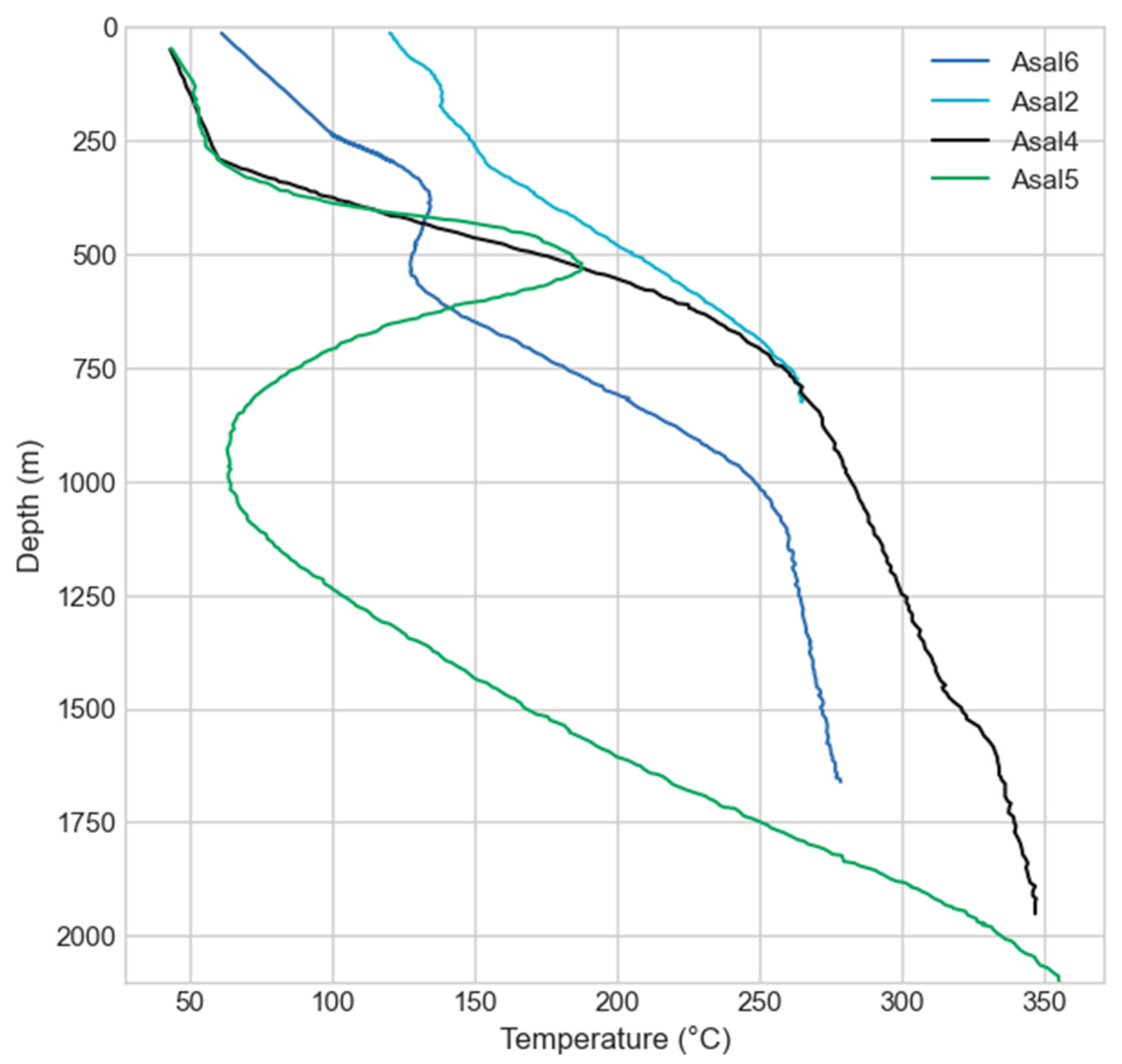
Figure 1). These wells have confirmed the existence of an intermediate reservoir located between 300 and 700 m depth, with a maximum temperature of 185 °C, and another potentially deep reservoir located between 1200 and 2000 m depth, with a maximum temperature of 260–280 °C (Figure 2). However, production tests proved to be ineffective for a continuous commercial geothermal energy production over time for two reasons:
  • The geothermal fluid produced in the wells drilled south-west of the rift (wells A1, A2, A3, and A6), which reached the deep reservoir, had a salinity ranging up to 120 g/L, and wells were subject to scaling and corrosion problems. The solutions considered at that time with chemical inhibitors were not satisfactory [16].
  • The wells drilled in the center of the rift (wells A4 and A5) intercepted formations with low permeability, even if a higher temperature (345 and 360 °C, respectively) was measured at their base.
The authors of [3] showed that the deepest geothermal fluid from the wells is constituted by a mixing of seawater and Asal Lake water, interacting with basalt rocks at 260–270 °C. The water stable isotopes also suggest a contribution of meteoric water [15], similar to that observed in the Korilii, Eadkorar, and Eounda Alifitta thermal waters, which could mainly be the meteoric water that transits from Asal local rift to Sakalol-Harralol depression, located at the north-west of Asal Lake, or/and the meteoric water coming from the deep circulating regional aquifers [11,12,13,14]. The low boron concentration observed in these deep waters suggests the existence of a steam phase in the geothermal system [3]. The existence of such a zone with dominant vapor is in agreement with the conclusions relative to the gas and steam condensate data drawn by [11] and the conceptual geothermal model proposed by BRGM [10,11,12]. The equilibrium temperature calculated from all gaseous reactive species associated with these well waters, except H2S, is very close to that measured at the bottom of the geothermal wells Asal 3 and Asal 6. This temperature corresponds to that of the identified geothermal reservoir and varies between 250 and 270 °C. According to [3], the geothermal waters located at a depth between 300 and 700 m correspond to a mixing between the deepest geothermal fluid and seawater. The circulation of hydrothermal fluids in the northern part of the rift is believed to happen deeper than in its southern part [17].
Assuming the highly saline water of Asal Lake contributes to the recharge of the geothermal reservoir, this contribution is relatively recent as the water of Asal Lake was fresh and its salinity was recently acquired [3,4,5,6,7,8,9]. This constrains the fluid circulation time in the deep hydrothermal system located between 1 and 3 km, having high enthalpy. The water level of Asal Lake 9 to 6 thousand years ago was 160 m above sea level. Over the past 5 to 6 thousand years, the level has declined by 310 m and the lake level is currently 150 m below sea level [9]. This level has remained constant for the last centuries. Therefore, this suggests that, despite the intense evaporation from the arid climate of the area and the infiltration of water from the lake, this evaporation of lake water is compensated by a constant recharge mainly supplied by the Ghoubbet Sea.
The Asal 2 and Asal 3 wells are believed to penetrate the potential deep reservoir unit, but Asal 2 well was non-productive, although a temperature of 230 °C was measured at a depth of 923 m, while the Asal 3 and Asal 6 (located with a distance of about 300 m) were producers with permeable zones at a depth of 1030 m (Figure 2). The fluid produced was hyper saline and essentially composed of liquid at 260° C [16].

3. Methods

An electrical resistivity model deduced from magnetotelluric surveys was used in this study to better understand the circulation of seawater through normal rift faults. Using the geoelectrical model, a 2D hydrogeological model was developed for numerically simulating multiphase flow and heat transfer, in order to better understand and quantify the flow dynamics and the development of possible hydrothermal reservoirs.
To better understand the role of seawater and the origin of thermal springs at the periphery of the Asal Lake, the 2D numerical model of coupled and multiphase flow and heat transfer was developed with the HYDROTHERM software provided by USGS [18,19].

3.1. Magnetotelluric Data Acquisition and Processing

Generally, the presence of fluids in porous rocks and their interconnections, the types of minerals, and the temperature and pressure in the rocks contribute to the variation of electrical resistivity. Hydrothermal fluids and the existence of a layer of clay that acts as a cap rock present on the roof of a hydrothermal reservoir are usually identified as highly conductive areas, while, on the other hand, gas reservoirs and cooled magma are identified as less conductive areas [20].
Between 2007 and 2008, a survey including 81 magnetotelluric (MT) stations was carried out in the Asal Rift by the Icelandic company ISOR [16]. The geographical distribution of the MT stations, which are roughly 1 km apart, covers a large part of the Asal Rift (Figure 1). The instrument used to record the data was a Phoenix MTU-5 system and has the ability to record the temporal variation of the three components of the magnetic field (Hx, Hy, and Hz) and the two components of the telluric field (Ex and Ey). A reference station, located 10 km from the study area, was used to correct and reduce the local noise of the MT signals [21]. The data collection time was 48 h. For each site, time series were converted from time domain to frequency domain impedance tensor [22]. The frequency range of the data varies from 12.9 × 10⁻⁶ Hz to 400 Hz and corresponds approximately to a depth of investigation of the MT signal of more than 12 km inside the earth.
In this study, a 1D inversion of each station of the MT data was achieved. The apparent resistivity of the squared sum of the components of the invariant impedance [23] was inverted using the Occam algorithm [24]. This impedance is expressed as follows:
Z SSQ =   Z xx 2 + Z xy 2 + Z yx 2 + Z yy 2 2
where Zxx, Zxy, Zyx, and Zyy are the elements of the impedance tensor Z. Generally, the invariant determinant model is used, but, recently, ref. [25,26] have shown that the determinant model is affected by galvanic distortion at depth. These authors argue that this model tends to reveal more conductive geological structures in the presence of distortion. Another invariant type of model named SSQ (sum of squared elements) is used because it is less affected by the distortion and more appropriate to obtain a first representative approximation of the regional electrical resistivity [25,26].
In this study, an uncertainty of 10% apparent resistivity was assigned for several soundings, except seven soundings with up to 20% uncertainty. The signal in the so-called dead-band, which corresponds to the 5 to 20 s period interval, was low and the resulting uncertainty higher. Moreover, the uncertainty assigned for the phase was 2.5°. With this approach, an electrical resistivity model was developed, where data from all sites were interpolated and interpreted to infer concepts about underground fluid flow. The inversion results of an electrical conductivity model are presented in Section 4 below, helping to evaluate the role of the Asal Rift in groundwater circulation interacting with deep hydrothermal fluids and to delineate the presence of a hydrothermal system located at a depth between 1.2 and 2 km.

3.2. Conceptual Model and Numerical Simulations

High enthalpy geothermal resources required to generate electricity are generally found in areas where magma is introduced into the shallow crust (<10 km) and hydrothermal convection takes place over intrusive hot bodies. For a convective-type geothermal system such as the Asal Rift, the most appropriate conceptual model consists of the following elements [27]. A deep magmatic intrusion that is covered by a host rock. The latter hosts permeable reservoir formations that are covered by a cap rock close to the surface. Based on the structure of this type of geothermal system and the results of the geothermal wells data (Figure 2), a conceptual model of the Asal Rift was set up, helping to approximate the thickness of the seawater intrusion towards Asal Lake. The 2D conceptual model used to define the geometry of the numerical model was based on an interpreted resistivity section inferred from the 1D electrical resistivity model developed in this study. This 2D section is parallel to the rift axis (Figure 1) and was chosen because of the presence of productive geothermal wells (Asal 3 and Asal 6) along this section, and is parallel to the believed direction of regional groundwater flow. The temperature profile of the Asal 6 well was used to calibrate the numerical model.

3.2.1. Multiphase Flow and Heat Transport

Simulation of multiphasic flow and heat transport is challenging because it is difficult to consider the critical point to set the appropriate thermodynamic state of the fluid in two phases. The pressure–enthalpy formulation that defines the thermodynamic state of the fluid in two phases can be used to avoid this problem, which was done in the HYDROTHERM code [28]. The governing equations used in the HYDROTHERM code are expressions of mass and energy conservation formulated in terms of pressure and enthalpy. As no potentiometric-head function exists for density fields that depend on temperature, pressure is chosen as the dependent variable for fluid flow. All pressures are expressed as absolute and the water-component flow equation is based on the conservation of water mass in a volume element, coupled with Darcy’s law for multiphase flow through a porous medium [19]:
t [ φ ( ρ w S w + ρ s S s ) ] · k k r w ρ r w μ w [ P + ρ w g ] · k k r s ρ r s μ s [ P g + ρ s g ] q s f = 0
where φ is the porosity (dimensionless), ρ is the fluid density (kg m−3), Sw is the saturation of liquid phase (water) and Ss is the saturation of the gas phase (steam or air; dimensionless), k is the porous-medium permeability tensor (m2), kr is the relative permeability (dimensionless), μ is the viscosity of fluid (Pa s), P is the fluid pressure in the liquid phase (Pa), Pg is the fluid pressure in the gas phase (Pa), g is the gravitational constant (m s−2), qsf is the flow-rate intensity of a fluid-mass source (positive into the region; kg s−1 m−3), t is the time (s), and ∇ is the spatial gradient (m−1). The phase subscripts w and s refer to water (liquid phase) and steam (gas phase or vapor phase), respectively. In the single-component (water) zone, pg = p because the capillary pressure is assumed to be zero. As any point in the mesh, it can be a single component or two component zone and the saturation constraint is Sw + Sg =1.
The thermal-transport equation is based on the conservation of enthalpy in both the fluid phases and the solid phase of the porous medium, in a volume element of the region. So, enthalpy is a derived property containing both internal energy and flow energy. Thus,
t [ φ ( ρ w h w S w + ρ s h s S s ) + ( 1 φ ρ r h r ) ] · K a I T + · φ ( ρ w h w S w v w + ρ s h s S s v s ) q s h = 0
where h is the specific enthalpy of the fluid phase (J kg−1), hr is the specific enthalpy of the porous-matrix solid phase (J kg−1), ρr is the density of the porous-matrix solid phase (kg m−3), Ka is the effective thermal conductivity of the bulk porous medium (combined liquid, gas, and solid phases) (W m−1 K−1), I is the identity matrix of rank 3 (dimensionless), T is the temperature (°C), and qsh is the flow-rate intensity of an enthalpy source (positive into the region; W m−3).
The main assumptions underlying Equations (2) and (3) that are solved in HYDROTHERM are the following: capillary pressure effect is negligible, porous medium and fluid are in local thermal equilibrium, the fluid is pure water, heat transfer by radiation and dispersion can be neglected, Darcy’s law is valid with two phase forms, and relative permeability is a nonhysteretic function of liquid volume saturation.

3.2.2. Spatial and Temporal Discretization

The 2D conceptual model to simulate extends 14 km horizontally (Figure 1) and 3 km vertically from the land surface. The model geometry in the HYDROTHERM simulator is discretized with a regular 100 × 100 grid. The simulation time span to reach a quasi-steady state temperature regime was 100,000 years and an initial time step of 0.001 year was considered. An automatic time step algorithm is used in the simulator, where smaller time steps are selected when conditions are changing rapidly and maximum values for changes in pressure, enthalpy, and liquid saturation are specified before running the simulation [19]. In our study the maximum changes in pressure, enthalpy, and saturation are 10%, 5%, and 0.03, respectively. This results in a maximum time step of 1000 years. The independence of the mesh is presented to demonstrate the accuracy of the solution. In this study, two different grids were considered with two different initial time steps.

3.2.3. Initial and Boundary Conditions

Numerical modeling of continental or subaerial hydrothermal systems often considers the upper system flow boundary to be the water table of shallow aquifers affected by topography [18,29,30]. Therefore, initial conditions are an initial temperature of 20 °C with an atmospheric pressure of 1 atm at the surface of the 2D model, a geothermal gradient of 49 °C/km, and hydrostatic pressure increasing with depth. A heat flux of 100 mW/m2 was fixed at the base of the model and the surface boundary has a constant temperature of 20 °C. A pressure of 1 atm was also considered at the surface boundary. The base of the model is considered impermeable with no flux. Constant temperature and pressure determined from the initial conditions were imposed on the lateral boundaries of the model in order to take into account the variation of the geothermal and the pressure gradients at depth. This allowed to establish the temperature and pressure gradients according to the topography and the water table depth inferred from the conceptual model. Five different simulation scenarios are presented below. For all scenarios, a deep resistive structure named R2 was taken as a magmatic intrusion or heat source, and a heat flux of 2700 mw/m2 was fixed at the base of this R2 structure. This is the base case scenario where the boundary conditions presented above are used.
Numerical simulations conducted in magmatic hydrothermal systems [18,31] showed that the representation of the topography is an important factor to reproduce regional groundwater flow driven by the topography. This was taken into account to better evaluate the dynamic of groundwater flow between the Asal Lake and Ghoubbet Sea. In addition, the influence of infiltration from rainfall in geothermal systems is not negligible, but the impact of rainfall in the hydrothermal activity is commonly limited in the upper part [32] and may not prevail in the deeper part of the hydrothermal system, as in the case of Asal Rift. The impact of rainfall was not simulated as the numerical simulations considered confined flow.

3.2.4. Hydraulic and Thermal Properties

The geological units considered in the conceptual 2D model were interpreted from the 1D electrical resistivity model developed in this study. Hydraulic and thermal properties of each unit were defined according to Table 1, used as the base case scenario and noted as scenario 1. Then, four other different scenarios were conducted in order to evaluate the sensitivity of the results to changes in the main hydraulic parameter (permeability) of the geological units. Three permeable vertical conduits that can be associated with fault zones were added and coexist to evaluate the possible impact of fault zones. The choice of emplacement and geometry of these faults was based on the interpretation of the inverted electrical resistivity profile developed in this study. Thus, properties of faults remain the same of those of unit C1 (Table 1), but with higher isotropic permeability equal to 2.17 × 10⁻¹⁴ m2. In scenario 2, a permeability dependent temperature in the potential deep reservoir unit was adopted with an isotropic permeability of heat source equal to 10−17 m2. Scenario 3 was simulated to understand the behaviour of the system in the deeper part without permeability dependent temperature. To do this, an isotropic permeability was assigned to both the heat source (10−17 m2) and the potential deep reservoir unit (10−15 m2). This permeability value assigned in the potential deep reservoir unit is of the same order of the one estimated from the production test of well Asal 3, which reached the potential deep reservoir, which was equal to 6.3 × 10⁻¹⁵ m2 [33]. The conditions of scenario 4 are similar, but a permeability dependent temperature inside the heat source unit was used. Finally, scenario 5 was simulated with permeability anisotropy within the near-surface aquifer C1, which was assigned to the model to investigate how it can influence the regional groundwater flow. Horizontal permeability was set one order higher than the one of the base case scenario. The purpose of this scenario 5 was to simulate the predominance of horizontal fluid movements over vertical movements within this geological formation and hypothesize the behaviour of the system in such conditions. The properties of all units remain the same as those of scenario 1, except for the horizontal permeability in the unit C1, which was equal to 2.17 × 10⁻¹⁴ m2.
In the crust, thermal conductivity decreases with increasing temperature [34]. The formulation developed by [34] for crystalline rocks with a temperature range between 20 and 500 °C was taken into account, where the thermal conductivity value at 20 °C is 2.5 W m−1 °C−1. To consider the effect of latent heat of crystallization, a linear temperature-dependent rock heat capacity relation was adopted, which doubles from 900 at temperatures below 100 °C to 1800 J kg−1 at temperatures greater than 500 °C. This linear relationship was based This linear relationship was based on the approach initially developed by [34] and then used by [35] for similar modeling work.
Temperature-dependent rock permeability was formulated for both the potential deep reservoir and heat source (Table 1). This formulation is the same as that developed by [29] for magmatic hydrothermal systems, where permeability increases with the decreasing temperature. Thus, the permeability of the heat source with a temperature range of 400–500 °C is one order of magnitude less than the one of the deep reservoir with a temperature range of 200–400 °C.
In such systems, fluid flow is mainly controlled by processes such as thermal pressurization, buoyancy, and magmatic exsolved fluid. Our hypothesis is based upon the existence of deep hydrothermal circulation in the Asal Rift and the absence of a magma chamber at a depth less than 5 km [4]. Thus, the fluid pressure originating from the heat source unit may have allowed rocks to fail and created permeability within the potential deep reservoir unit.

4. Results

The results of 1D electrical conductivity model are initially presented and followed by the results of fluid flow simulations.

4.1. 1D Electrical Resistivity Model

Observed and simulated electrical resistivity fits with an average root mean square (RMS) misfit of about 0.1. The match of electrical resistivity and phase at each MT station appears reasonable, as can be seen for resistivity, and phase curves of all MT sites along the 2D MT profile (Figure 1) are presented in Figure 3.
The H fault (Figure 1 and Figure 4) delineates two distinct zones of electrical resistivity. The north-east part of this fault is defined as a conductive zone, while the south part is less conductive (more than 20 Ω.m). The geometry of the Fieale Caldera corresponds to a well-defined zone of electrical resistivity of the order 20–30 Ω.m (Figure 1 and Figure 4). The different electrical iso-resistivity maps in Figure 4 show a gradient of electrical conductivity that increases in the direction from the south-west to the north-east. This change of the conductivity gradient is clearly visible and evident at depths of 1640 and 1840 m (Figure 4).

4.2. 2D Conceptual Model

The conceptual model of Figure 5 was defined using the available electrical resistivity data interpreted along a cross section more or less parallel to the Asal rift axis (Figure 1). A top layer of high resistivity (R1) is associated with unsaturated formation near the surface. The underlying layer with a low resistivity C1 is considered as an aquifer, which can host shallow or intermediate reservoirs, as evidenced by temperature profiles of wells Asal 6 and Asal 3 (Figure 2). These temperature profiles show convection cells with a change in geothermal gradient at a depth between 300 and 600 m that can only occur in permeable layers with fractures.
Layer C2 can be a cap rock covering the formations hosting deep hydrothermal reservoirs, which is referred to here as the potential deep reservoir unit in the numerical model. The highly resistive R2 structures can mostly likely be associated with intrusive bodies.

4.3. Numerical Simulations

Mesh and time step independence were investigated to make sure numerical simulations are reliable. A comparison between different grids for scenario 1 at the location of Asal 6 well at a depth of 1500 m is presented in Appendix A. The results with a 100 × 100 grid and initial time step of 0.001 year are presented in Figure 6 and Figure 7. Furthermore, a mesh with a 40 × 100 grid with an initial time step of 0.01 year was considered (Figure 6) and the patterns of flow and heat transport observed were similar to those of mesh with a 100 × 100 grid (Figure 7). We can deduce and argue that our solution is independent of the choice of the grid and the choice of the initial time step. One should keep in mind that the HYDROTHERM software uses an algorithm allowing an automatic time step [19] in which only the initial time step is set by the user.
The simulation results of scenario 1 and scenario 2 (Figure 6 and Figure 7) show the upwelling of a warm fluid or an upflow zone that propagates from the heat source at the model center toward Asal Lake and toward the sea, but to a lesser intensity. The development of convection movements is visible inside the deep potential reservoir unit that can likely host localized hydrothermal reservoirs. Scenarios 3 and 4 present similar flow and temperature patterns with the presence of three flow zones at a distinct depth. Groundwater circulation toward Asal Lake inside the aquifer C1 can be identified and the widening of the deep upflow zone of hydrothermal reservoir from the center to the sea can be observed. High velocity flow vectors also appear in the center of the rift at a depth between 900 and 1800 m, particularly inside the faults zones, where hot ascent fluid in the fault close to the sea and cold descendant fluid in the fault close to Asal Lake can be observed. This can be associated with a mixture of descending cold groundwater with the ascending deep hydrothermal circulation over a depth of about 500 m and driven by the temperature gradient (Figure 7). Scenario 5 captures the same temperature patterns as the results of scenarios 1 and 2, but with strong flow vectors inside the unit called C1, noted here as a shallow aquifer. Obviously, the system behaviour remains the same in the deeper part even with the presence of significant lateral flow in the upper part of the system (Figure 7).
The Asal 3 and Asal 6 wells are believed to be penetrating the deep potential reservoir unit. The full comparison between simulated and observed temperature in well Asal 6 for each scenario is shown in Figure 8. The simulated temperature is about 255 °C in scenario 1 at a depth of 1600 m, which approximately corresponds to the measured temperature at the bottom of Asal 6 well (265 °C at a depth of 1700 m). In fact, the measured temperature matches with the simulated temperature of scenarios 1, 2, and 5, except in the upper part above 600 m depth (Figure 8). The comparison between the measured and simulated temperature for scenario 3 is not presented as it is the same as scenario 4 (Figure 8).

5. Discussion

The directions of faults and fractures are parallel to the direction of believed groundwater flow (Figure 1 and Figure 4). Unfortunately, the available MT data do not cover the entire area of the emerged Asal Rift. A lack of data in the area of the normal faults ε and δ to the north-east of the rift limits the interpretation (Figure 1). However, previous geochemical analyses conducted by [36] in littoral thermal springs could help to place our interpretations in a logical context and may explain the origin and the evolution of thermal waters that are not far at the eastern flank of the normal faults ε and δ located at the north-east of the rift. These authors conclude that a mixture of hot seawater with cold seawater emerges through the fractures. Moreover, the presence of deep hot seawater-derived geothermal fluid with a temperature of 210 °C was confirmed [37]. Despite the lack of data in this zone, our interpretation of pronounced fluid circulation at the north-east of the rift can be justifiable. The comparison between the 87Sr/86Sr ratio and strontium concentration of the brine waters from the Red Sea bottom and Asal Lake have indicated that Asal Lake is a better location to study how hydrothermal fluids of seawater origin may evolve in the Red Sea rift [38].
The descriptive lithology of the wells drilled in the Asal Rift consists mainly of a succession of basaltic series, which were deposited over geological time and have different ages [39]. Even if the abundance of shale and/or graphite is known to cause a decrease in electrical resistivity [21], no significant quantity of the latter is found in the wells drilled, and more precisely between 1 and 2 km depth [39]. Within the Earth’s crust, the dominant electrical conduction mechanism is electrolytic [
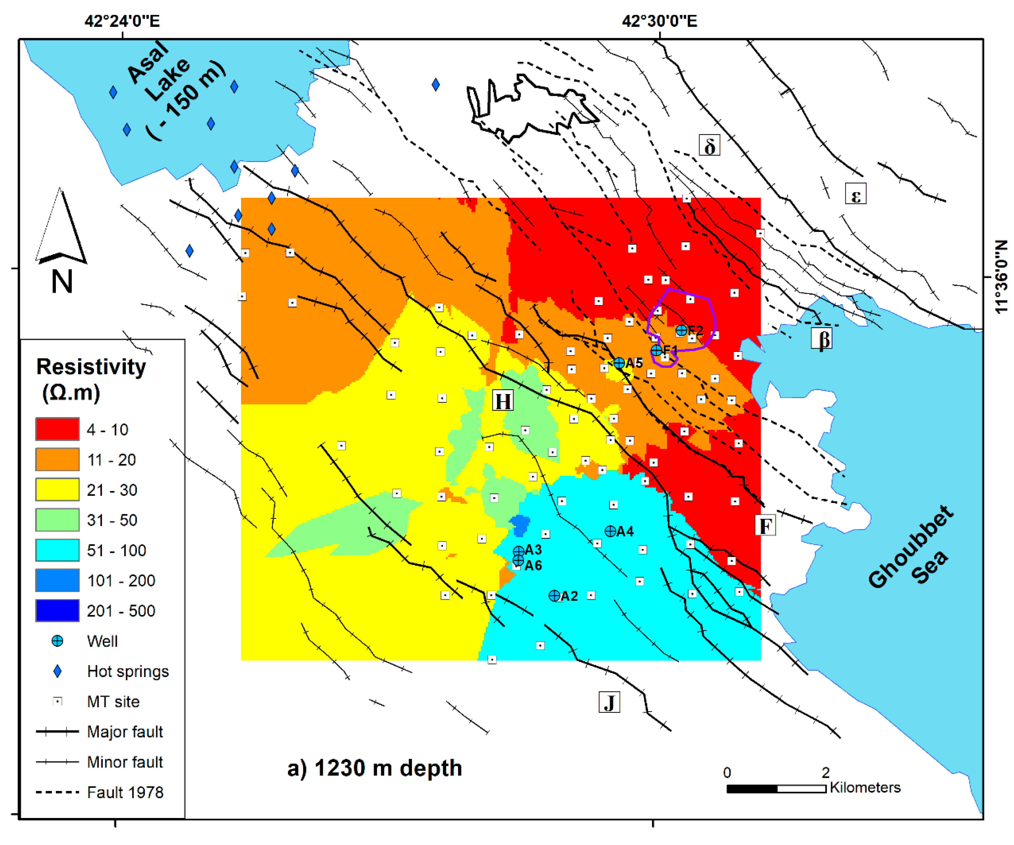
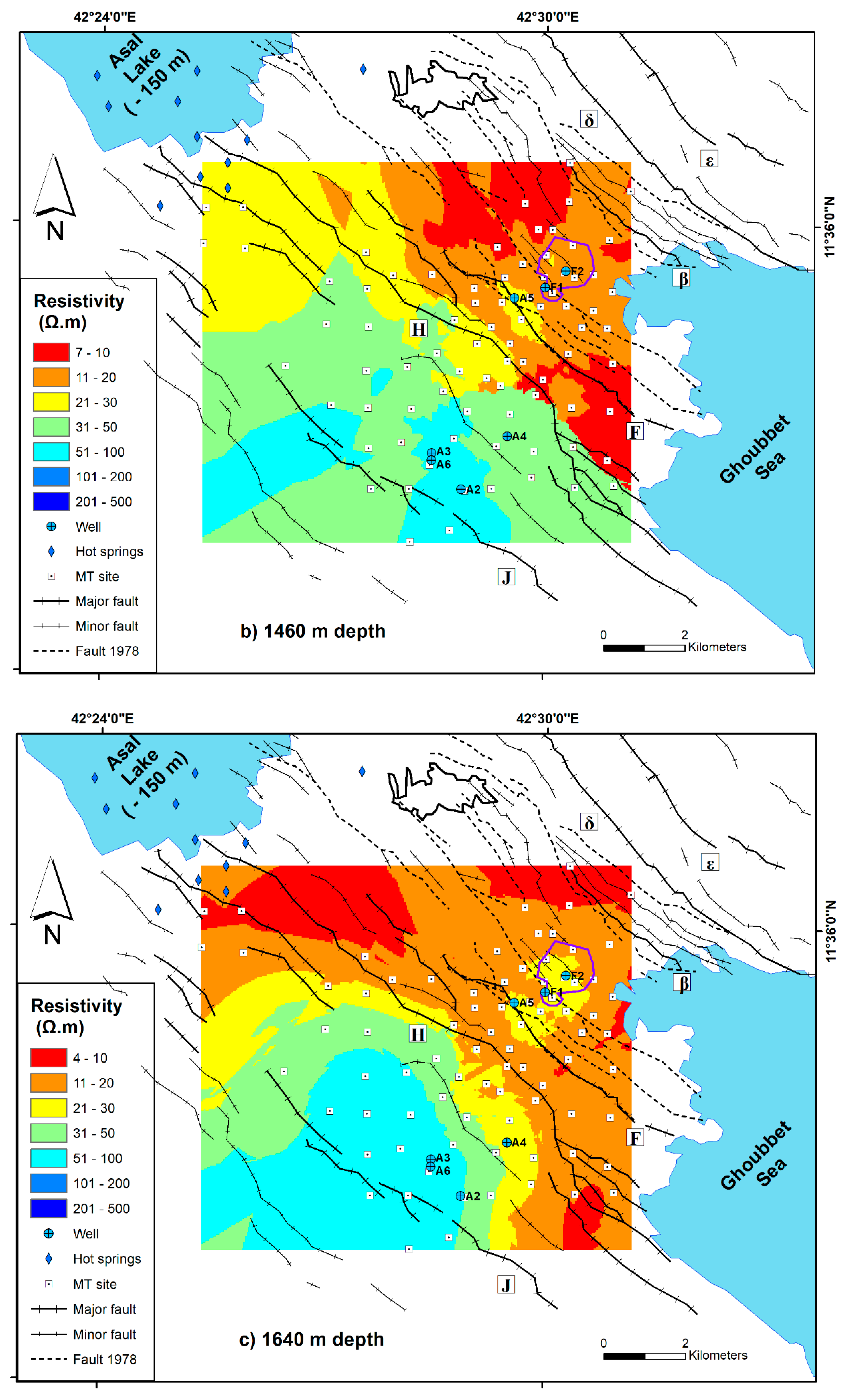
21]. Therefore, low electrical resistivity in the context of the Asal Rift is generally interpreted as an indicator of the presence of a fluid. At depths of 1200 and 1400 m (Figure 4), groundwater seems to be present mainly between the H fault and the δ fault according to the following evidence. In this zone, observed fractures were caused by the tectonic and volcanic activity associated with the eruption of the Ardoukoba volcano that occurred in 1978 (Figure 1). The low electrical resistivity suggests the presence of water and hence more important flow to the southeast between the H and F faults, and to the north-east of Fieale Caldera. The existence of dykes at a depth near the rift axis (between the F and β faults) has been hypothesized based on the deformations observed at the surface [9]. In this case, rift extension and subsidence are controlled by dyke injection. Moreover, the stretching model of Asal Rift is likely accommodated by the magma activity [
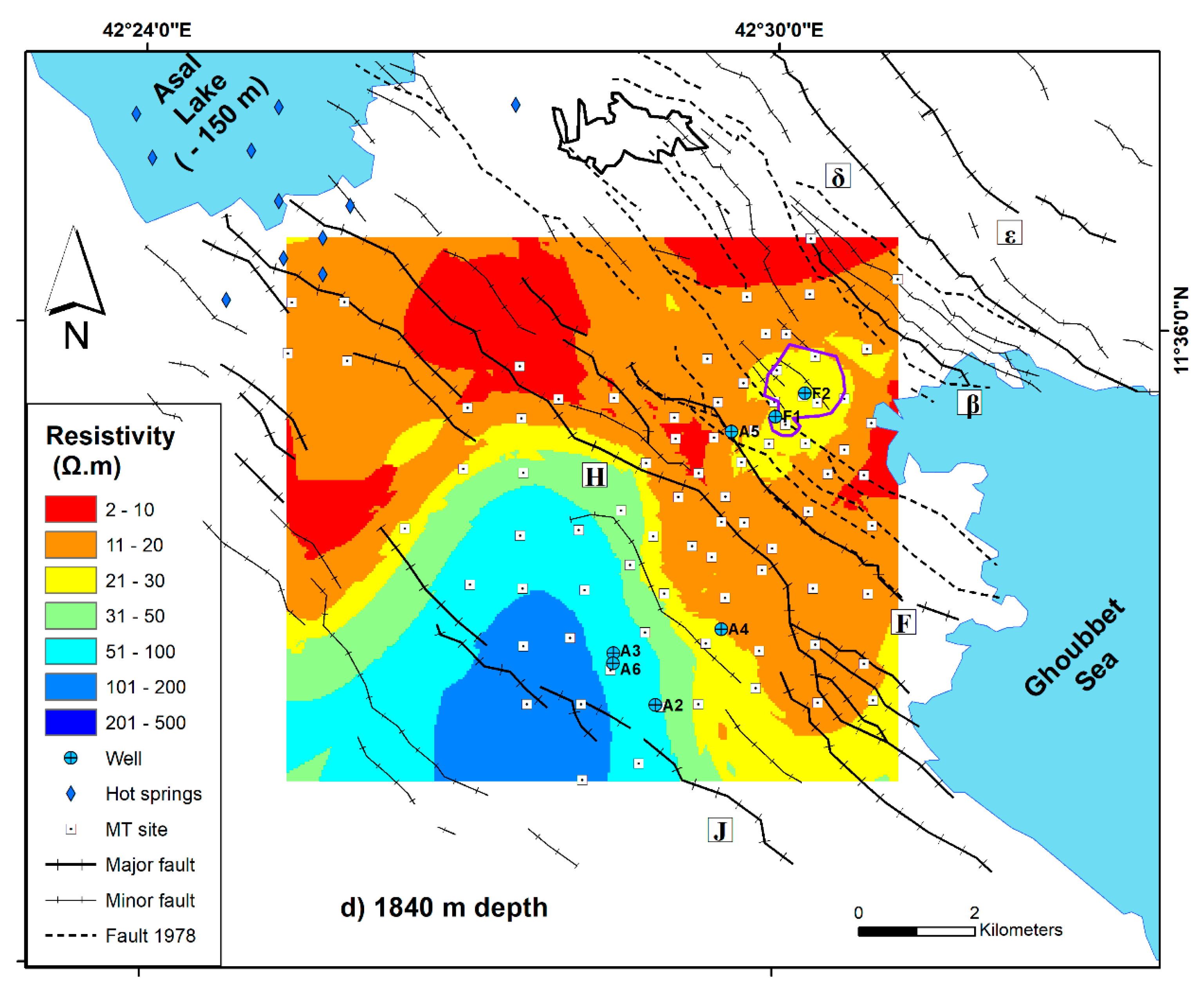
40]. This extension can result in open cracks where groundwater flows easily. The proximity of the sea and the coexistence of recent open faults and fractures is a fair evidence for such flow illustrated with the simulations. The electrical resistivity model, especially images obtained at a depth between 1.2 and 2 km (Figure 4), indicates a possible hydrothermal system in the north-east part of the Asal Rift and with more pronounced regional groundwater flow in this area rather than in the south-west zone (Figure 4). Considering the contrast in electrical resistivity between the north-east and south-west parts of the Asal Rift, it seems likely that the hanging wall of the H fault acts as a hydrogeological barrier separating the Asal Rift between two zones. A first conductive zone, whose high electrical conductivity is due to the presence of groundwater, as well as a second less conductive zone with an increase of the electrical resistivity gradient towards the south of the rift, imply lower porosity and/or less groundwater in pore space and fractures. Only the major J fault and the minor fault passing through well Asal 4 exist in the south zone of the Asal Rift. In addition, according to the bathymetry map of the region, the J fault is not connected to the Ghoubbet sea. The absence of the open cracks or fractures observed with the November 1978 eruption in the southern zone of the Asal Rift is another argument that limits the possibility of possible fluid flow or water infiltration in this sector, while the presence of activated faults in 1978 in the northern part is dominant (Figure 1).
Wells A5, F1, and F2 were drilled in the north-east zone of the H fault, but only the temperature profile of well A5 was available for this study (Figure 2). This temperature profile shows a first convection cell from 300 to 500 m and a second convection cell from 500 to 1200 m, and then a constant geothermal gradient that can be related to heat conduction between 1.2 and 1.8 km. This information, therefore, correlates with the conductive zone to the north-east of fault H. Furthermore, the geothermal gradient estimated between 1.2 and 1.8 km in well Asal 5 is 18.7 °C/100 m. In addition, well Asal 5 is located in a relatively conductive zone with an electrical resistivity greater than 20 Ω m, which can corroborate the absence of groundwater that can have a high salinity associated with electrical resistivity less than or equal to a value of 10 Ω m [21]. This Asal 5 well can be close to a heat source where heat is transferred by deep conduction, resulting in a strong conductive geothermal gradient at a depth between 1.2 and 1.8 km. The absence of groundwater circulation between 1.2 and 2 km in this well is corroborated by both its temperature profile and the electrical resistivity model presented in this study. The latter also shows the Fieale Caldera in close proximity to well Asal 5 has a particular electrical resistivity range of 20–30 Ω m. It is highly probable that this resistivity is characteristic of the nature of the rock in this Caldera zone, which can be hot, but less permeable, limiting the circulation of fluid. Another important fact is that hydrothermal mineral assemblage is in good agreement with the measured temperatures in all geothermal wells of Asal Rift, except for well Asal 5 [39], where a chlorite-epidote mineral assemblage zone that normally should exist at a high temperature was observed at a depth between 500 and 1200 m, where an important temperature inversion was measured (Figure 2). This information is helpful allows to assume that a pre-existing high temperature reservoir can have existed before the infiltration of cold sea water, and the temperature inversion may likely be related to a recent infiltration of seawater.
Geodetic measurements indicate that the opening of the Asal–Ghoubbet Rift has a velocity of 16 mm/year and an opening direction perpendicular to the rift axis, highlighting the asymmetrical behavior of the Asal Rift [6]. These authors studied the horizontal and vertical deformation of the rift in directions parallel and perpendicular to the rift axis. They consider that the north-eastern part of the Asal Rift is the site of significant continuous deformation, whereas for its south-western part, the deformation is weak and practically non-existent. These results corroborate the presence of active normal faults in the north-eastern part of the rift and the existing seismic activity [4]. The rate of deformation along the axis perpendicular to the rift axis increases towards the north-east of the rift [6]. This is a surprising correlation between the increase in this deformation rate and the increase in electrical conductivity highlighted by the model developed in this work pointing in the same direction (Figure 4).
The regional groundwater flow affected by sea water was believed to be the main source of recharge to Asal Lake [
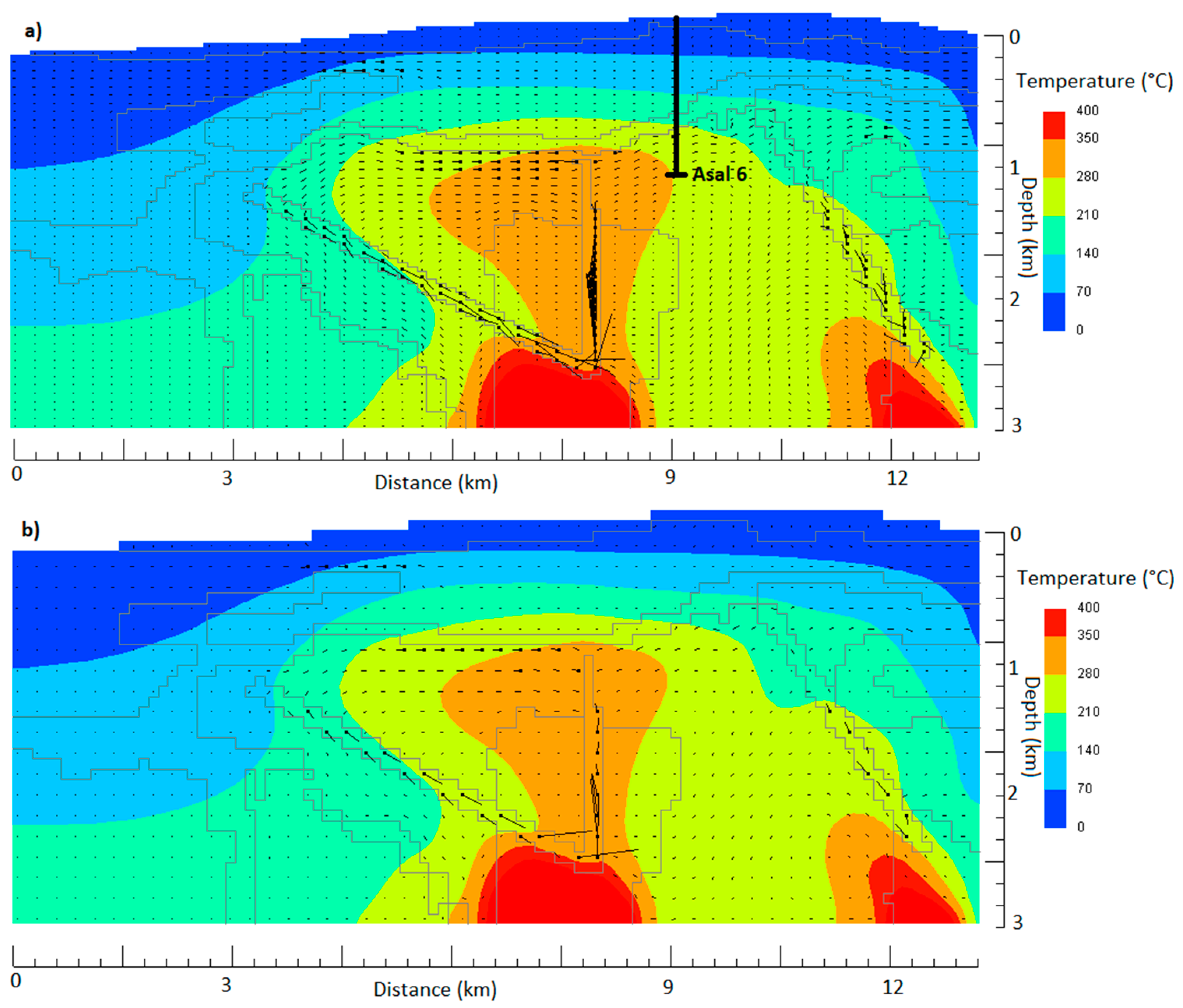
3], but our simulation results show the groundwater flow is directed toward both the Asal Lake and the Ghoubbet Sea, with a maximum point on the SE side diving flow in the two directions and a pronounced flow to Asal Lake. This can limit the pontifical depth of penetration of sea water intrusions near the surface. In this case, recharge of Asal Lake can occur through aquifer (C1), potentially containing fossil seawater that is likely fed by a deep hydrothermal circulation. In all the different simulation scenarios, it is important to highlight the evidence of groundwater flow into Asal Lake and hydrothermal circulation beneath Asal Lake and the Ghoubbet sea.
The superposition of three permeable zones with the predominance of flow towards Asal Lake and the Ghoubbet sea are important elements to advance the hypothesis of the existence of a large hydrothermal system under the rift that would be compartmentalized into these three permeable zones, which can be individualized under the tectonic activity and the injection of a deep heat source since the formation of the rift over the geological time. The subsurface flow at a depth between 300 and 700 m (Figure 7) can be influenced by the Ghoubbet sea and the local rift topography, while the intermediate flow at a depth between 1200 and 2000 m (Figure 7) is interpreted as the result of the development of a hydrothermal system, and the deep flow can be linked to a deep hydrothermal circulation feed by a heat source originating from a deep magmatic system (
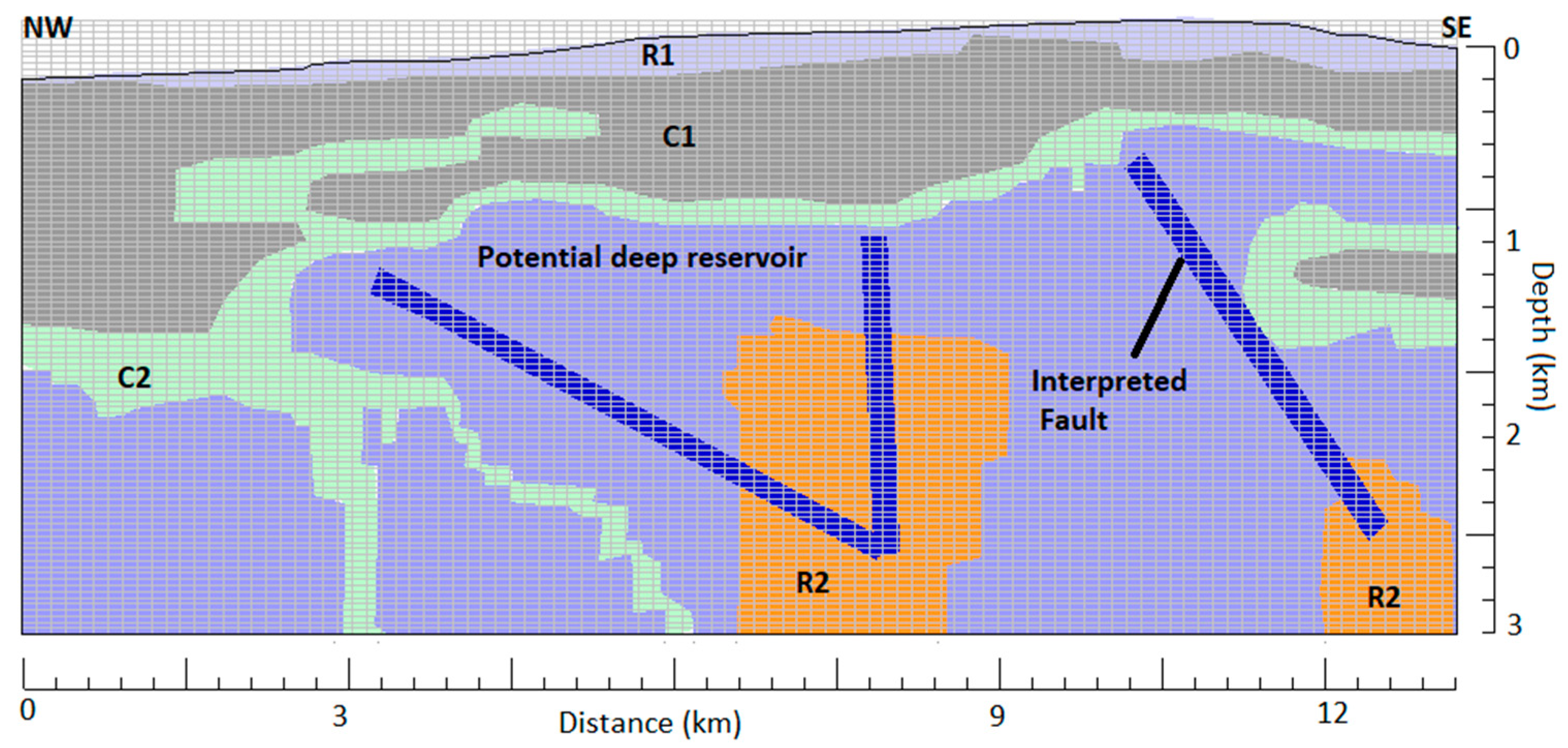
Figure 7). The presence of the cap rock layer limits possible communications between the second permeable layer, identified here as a potential deep reservoir, and the shallow aquifer C1 (Figure 5 and Figure 7), and facilitates the development of a hydrothermal reservoir in the formation, where this cap rock layer covers and helps to contain thermal energy in the potential deep reservoir.
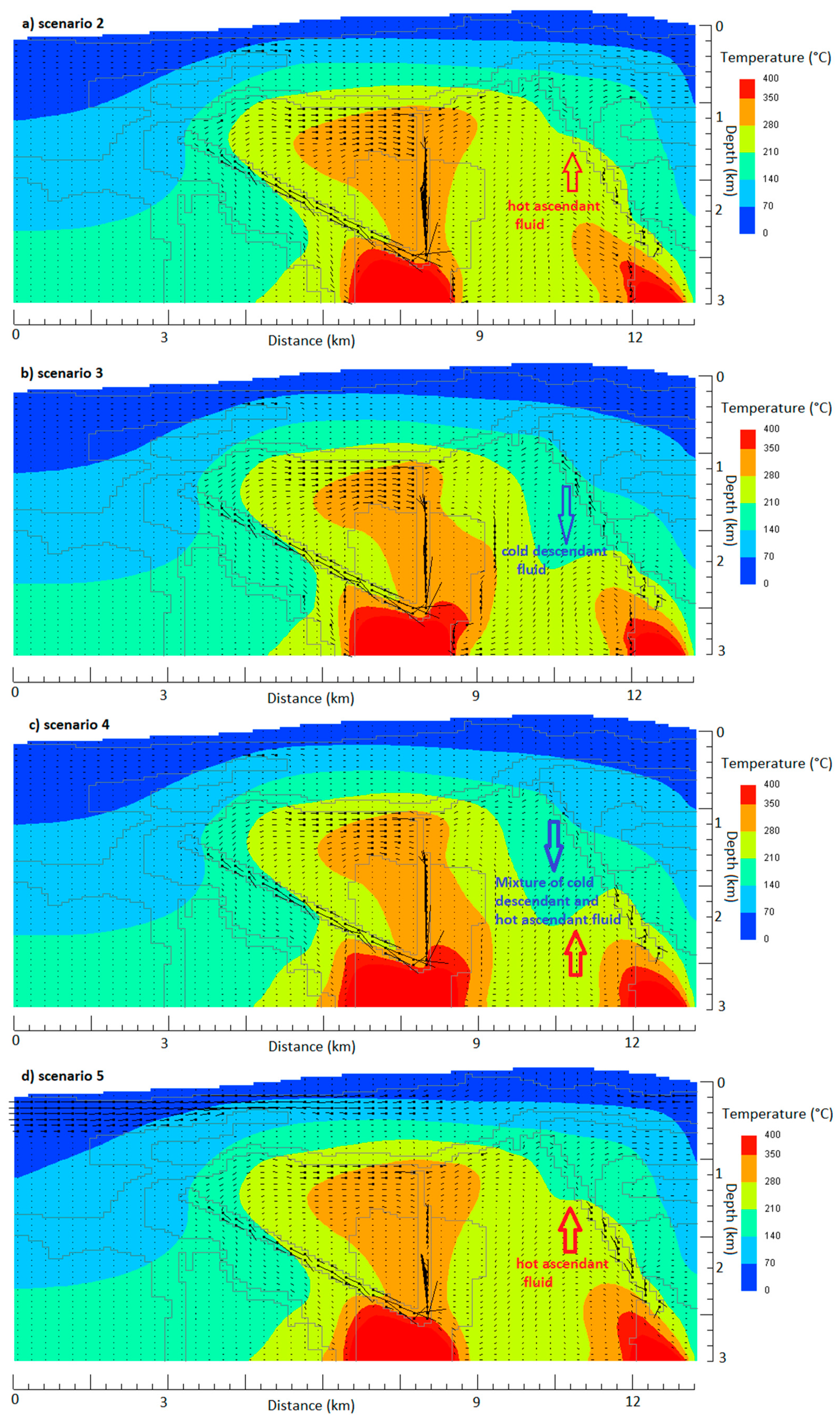
Similar simulation results obtained with scenario 5 (Figure 7) support the idea that regional flow variation is not strongly influenced by the permeability anisotropy in layer C1 of the conceptual model (Figure 5). In other words, the regional flow is mainly controlled by tectonics that affect deep structures and allow the deep heat source to be directed to shallower geological strata and formations. Simulations with an isotropic permeability of 10−15 m2 inside the deep reservoir and equal to 10−17 m2 inside the heat source were conducted for scenario 3 to indirectly evaluate the vertical dependence of permeability, which can decrease with depth. The development of hot convection cells within this unit was less pronounced than in scenarios 1 and 2 (Figure 6 and Figure 7). Scenarios with permeability dependent temperature (scenarios 1, 2, and 5) seem to be more realistic than scenario 3 with isotropic permeability. However, the results from scenario 3 are not representative of conceptual hydrothermal models proposed in previous studies [41,42], where hydrothermal activity is concentrated in areas with elevated topography. Hydrothermal activity in permeability dependent temperature scenarios better correlates with the central zone of high topography (Figure 6 and Figure 7). In scenarios 1, 2, and 5, the lateral extension of the hydrothermal reservoir with the isotherm 210 °C becomes important compared with the results of scenarios 3 and 4 (Figure 6 and Figure 7). This pattern is in good agreement with a previous study conducted in a tectonically active rift-ridge zone in Iceland [43]. The authors of this study confirm that emplacement and geometry of the upflow zones are mainly controlled by the location and the permeability values of fault zones. The geometry, location, and permeability values of fault zones remain the same in all the different scenarios for this study, but we deduce from our results that the permeability dependent temperature rock formulated in both heat source and potential deep reservoir can play a major role to reproduce a representative dynamic heat transfer in hydrothermal systems. Permeability dependent temperature formulated solely for the heat source unit may not produce significant variation when the potential deep reservoir is set with a constant permeability like the simulated conditions of scenario 4. In addition, the results are approximately the same as the results of scenario 3, where isotropic permeability was set for both the heat source and potential deep reservoir units. In such cases, we hypothesize that permeability dependent temperature would be an appropriate formulation in a hydrothermal system as in the Asal Rift, when it is adopted for both the heat source and potential deep reservoir or, uniquely, for the potential deep reservoir like in scenario 2.
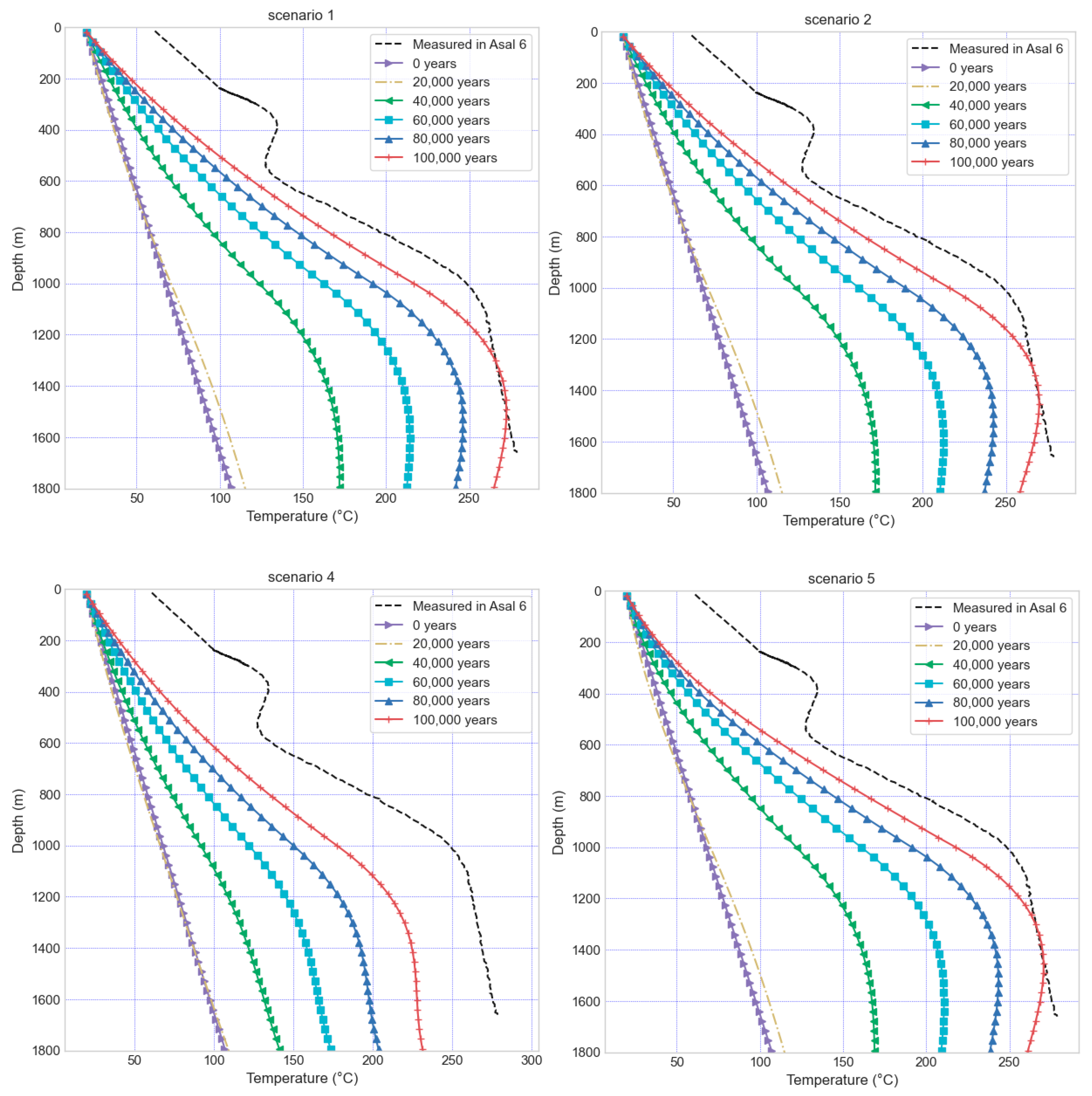
The comparison between the temperature profile measured in the Asal 6 well and the temperature simulated appears more realistic with scenarios 1, 2, and 5 compared with other scenarios (Figure 8). This indicates that the conditions used are representative of the rift and the associated thermal anomaly can be related to the injection of a magma forming a heat source and the development of vertical conduits qualified as active faults to convey this internal thermal energy. In scenario 4 (Figure 8), the system at the end of the simulation began to cooled down, as the temperature at 100,000 years is less than the temperature measured in well Asal 6. It can be reasonable to interpret this as a consequence of an extinguished deep hydrothermal fluid circulation inside the heat source layer, where permeability could be higher than that assigned in scenario 4. However, the shape of the simulated temperature profile at the location of well Asal 6 is maintained and has the same appearance as the measured temperature in well Asal 6. Furthermore, the same reservoir was recognized at a depth between 1050 and 1300 m in three wells, Asal 1, 3, and 6, and the geologic formation hosting this reservoir is called Dalha basal, which has an average age of 4 to 9 My, where temperatures measured in this reservoir range from 260 to 280 °C [33] and are close to the simulated temperatures in this study. In addition, permeability anisotropy considered in scenario 5 inside the C1 layer does not lead to cooling of the system and the simulated thermal state at well Asal 6 is close to the measured one (Figure 8). It can be assumed that the thermal anomaly caused by this near-surface groundwater flow has less effect at the global scale of the system. Nevertheless, the assumption of pronounced horizontal flow near Asal Lake in scenario 5 is corroborated by our interpreted conceptual model based on electrical resistivity inversion (Figure 5), where the thickness of the shallow aquifer called C1 increases toward Asal Lake. As results of MT inversion and numerical simulations showed, this study is focused for the potential deep reservoir between 1 and 3 km. The developed 2D model simulate a regional groundwater flow that gives a capture of fluid circulation in a regional scale. Then, the lack of a better correlation between measured and simulated temperature at Asal 6 well for the shallow part of the system above 600 m of depth (Figure 8) may be related to a localized fractures or convections cells. Another possible interpretation would be resulted by the difference of density fluid between the upper part of the system and the lower part. May be if a higher density fluid (as saline fluid) was considered in the shallow part than the deeper part, the shallow part of temperature profile measured at Asal 6 well could be well represented.
Temperatures measured in the thermal springs emerging on the periphery of Asal Lake range from 30 to 90 °C [3], and the results of the different scenarios show approximate emergence temperatures that corroborate with those measured in the thermal springs (Figure 7). Based on the chemical and isotopic characteristic of water in the Asal region, three main types of water may co-exist in the subsurface: seawater intrusion from Ghoubbet sea, Asal Lake water, and meteoric infiltration probably originating from the meteoric water that transits from Asal Rift to Sakalol-Harralol depression or/and the meteoric water coming from the deep circulating regional aquifer [14]. The low temperature emergence observed in the hot springs of group Manda [3], their chemical composition of which is close to that of seawater, and the high rate of flow show that seawater circulation through the faults and fractures is the main source of their recharge [15]. This information can be related to the emplacement of the hot springs group Manda that are close to the H fault and are aligned more or less to this H fault and with two other major faults located south of the H fault (Figure 1). Moreover, in this case, the information corroborates our hypothesis that seawater intrusion occurs where faults/fractures exist (Figure 1 and Figure 4).
Dissolved salts in water can change the phase conditions of liquid–vapor system and the phase relation of saline water approximated by the H2O-NaCl system is not the same as those of pure water considered in this study. In conditions of an H2O-NaCl system such as that of the Asal Rift, the temperature and pressure of liquid–vapor co-existence are above the critical values of pure water [44]. Despite that the fluid simulated from HYDROTHERM code is pure water [19], for saline geothermal fluid, the emplacement depth of intrusion controls significantly whether phase separation is dominantly carried out by boiling or by condensation [35]. Obviously, in this case, numerical simulations considering a saline geothermal fluid are expected to reveal the presence of a vapor phase, as proposed by the BRGM conceptual model [17]. This model is in good agreement with the gas chemical results of the Asal fumaroles and the water stable isotope data of their steam condensates [11], as well as the decrease of boron concentrations in the well geothermal fluids evidenced by geochemical analyses [3].
The total flow rate of geothermal fluid produced in well Asal 3 showed a considerable decrease of production rate and a decrease of bottom hole pressure, which were related to sulphide and silica deposits in the well with a total dissolved solids (TDS) of 116,000 ppm [33], suggesting a high potential of permeability reduction.
The δD and δ18O water stable isotope data for the geothermal fluids of the Asal wells and for some hot springs (Korilii, Eadkorar, and Eounda Alifitta groups; Figure 1) indicated contributions of meteoric water [3]. This meteoric contribution probably originates from the meteoric water that transits from Asal Rift to Sakalol-Harralol depression or/and the meteoric water coming from the deep circulating regional aquifer [14]. These authors showed, in the area of Sakalol-Harralol, the presence of hot springs, with high TDS Na-Cl waters, aligned in NW-SE along the main faults like in the Asal Rift. The high altitude zones of rift margins at the north and south do not seem to be potential recharge sources. However, a more representative numerical model can incorporate these zones and be tested to confirm or invalidate these hypotheses. As suggested by [14], the existence of a deep regional aquifer that may have a wide extension in Djibouti and where the Asal geothermal water has apparently common features in terms of chemical and water-isotope compositions is a good argument to highlight the need for a numerical multiphase model developed at a large regional scale. Coastal aquifers in Djibouti hosted geothermal water that could be more evolved in terms of water–rock interaction between deep fossil water and sea water intrusions [38].

6. Conclusions

This study emphasizes the importance of fault activity and its role in hydrothermal circulation. More specifically, the hypothesis of groundwater infiltration into Asal Lake is supported by numerical flow and heat transfer simulations performed after considering an electrical resistivity model of the area. The electrical conductivity model obtained after inversion of MT data indicates that faults can act as conduits for the circulation of water, notably the H fault, where the hanging wall of the fault behaves as a hydrogeological barrier. The variation of the electrical conductivity gradient and its increase from the south-west to the north-east of the rift are in agreement with previous work that brings to light the presence of horizontal and vertical deformation in the south-west to north-east direction. The 2D numerical model of flow and heat transfer developed in this study was used to better understand the groundwater flow and hydrothermal circulation. Furthermore, this model confirmed that flow is generally controlled by the presence of faults acting as conduits and driven by deep heat sources. Three flow zones were defined based on the interpretation of electrical resistivity and temperature profiles. The temperature simulated with our model having these three zones is correlated with the temperature measured in well Asal 6, and is thus considered representative of the heat transfer dynamics of the system. These three flow zones are shallow groundwater flow affected by seawater and topography, an intermediate flow with a hydrothermal circulation, and a deep flow related to the hot hydrothermal circulation originating from the magmatic heat source.
In the context of geothermal energy research, future exploration drilling can be located either along this major H fault or in the northeastern part of the rift to capture a significant flow of geothermal fluid that mainly comes from the underground circulation heated by the strong geothermal gradient existing under the Asal Rift. The target drilling zone could be the deep potential reservoir unit down to a depth of 3 km to better intercept permeable zones containing supercritical water or inside the potential deep reservoir at an intermediate depth between 1 and 2 km. The Fieale Caldera and its surrounding zones should be avoided as the presence of hot rocks is thought to produce low permeability in this area.
It could be interesting to complete the present study with a second electrical resistivity model including more MT sites covering the entire surface area of the Asal–Ghoubbet Rift and extending to the north-east of the rift, notably the north Ghoubbet zone, in order to better understand the limits of the hydrothermal system identified in our study and to establish a correlation on a larger scale between the electrical resistivity gradient and the deformation velocity gradient estimated by geodetic measurements [6]. In other words, such a complementary study will help estimate which are the underground circulation paths and proportions of seawater and meteoric water recharged through the faults in the hydrothermal systems identified in this study. According to the water stable isotopes data [14], infiltration of meteoric water can possibly occur from the meteoric water that transits from Asal Rift to Sakalol-Harralol depression or/and the meteoric water coming from the deep circulating regional aquifer. Similarly, the development of a 2D numerical model of flow and heat transfer down to a depth of 10 km can help to elucidate the role of magmatic intrusion in the deep hydrothermal circulation.

Author Contributions

Conceptualization, A.H.A., J.R., and B.G.; methodology, A.H.A.; validation, J.R., B.G., B.S., and A.H.A.; formal analysis, A.H.A.; investigation, A.H.A.; resources, J.R. and B.G.; data curation, A.H.A.; writing—original draft preparation, A.H.A., J.R., and B.G.; writing—review and editing, A.H.A., J.R., B.G., and B.S.; visualization, A.H.A.; supervision, J.R. and B.G.; project administration, J.R.; funding acquisition, J.R. and B.G. All authors have read and agreed to the published version of the manuscript.

Funding

This research was funded by the Islamic Development Bank through a PhD scholarship awarded to the first author as well as research funds attributed by the Natural Sciences and Engineering Research Council of Canada given to the second and third authors.

Acknowledgments

We would like to thank the contribution and support of the INRS. Gaeten Sakindi (Electricity Company of Rwanda), Abdourahman Haga, Awaleh Abdi, and Djama Robleh (Ministry of Energy and Natural Resources of the Republic Djibouti) are further acknowledged for their precious help on this project.

Conflicts of Interest

The authors declare no conflict of interest. The funders had no role in the design of the study; in the collection, analyses, or interpretation of data; in the writing of the manuscript; or in the decision to publish the results.

Appendix A

Table A1. Verification of mesh independence for simulation of scenario 1.
Number of ElementsTemperature at 1600 m Depth in Asal 6 Well
T (°C)
Absolute Value of Relative Difference (%)
1200238.931---
2400248.2570.039
4000254.3870.024
4800256.3270.007
10,000255.0950.004

References

  1. Bellani, S.; Gherardi, F. Thermal Overview of an Area NW of the Larderello Geothermal Field, Italy. GRC Trans. 2013, 37, 231–236. [Google Scholar]
  2. Mlynarski, M.; Zlotnicki, J. Fluid circulation in the active emerged Asal rift (east Africa, Djibouti) inferred from self-potential and Telluric–Telluric prospecting. Tectonophysics 2001, 339, 455–472. [Google Scholar] [CrossRef]
  3. Sanjuan, B.; Michard, G.; Michard, A. Origine des substances dissoutes dans les eaux des sources thermales et des forages de la région Asal-Ghoubbet (République de Djibouti). J. Volcanol. Geotherm. Res. 1990, 43, 333–352. [Google Scholar] [CrossRef]
  4. Doubre, C.; Manighetti, I.; Dorbath, L.; Dorbath, C.; Bertil, D.; Delmond, J.C. Crustal structure and magmato-tectonic processes in an active rift (Asal-Ghoubbet, Afar, East Africa): 2. Insights from the 23-year recording of seismicity since the last rifting event. J. Geophys. Res. Space Phys. 2007, 112. [Google Scholar] [CrossRef] [Green Version]
  5. Doubre, C.; Peltzer, G. Fluid-controlled faulting process in the Asal Rift, Djibouti, from 8 yr of radar interferometry observations. Geology 2007, 35, 69. [Google Scholar] [CrossRef]
  6. Vigny, C.; De Chabalier, J.-B.; Ruegg, J.-C.; Huchon, P.; Feigl, K.L.; Cattin, R.; Asfaw, L.; Kanbari, K. Twenty-five years of geodetic measurements along the Tadjoura-Asal rift system, Djibouti, East Africa. J. Geophys. Res. Space Phys. 2007, 112. [Google Scholar] [CrossRef] [Green Version]
  7. Manighetti, I.; Tapponnier, P.; Gillot, P.Y.; Jacques, E.; Courtillot, V.; Armijo, R.; Ruegg, J.C.; King, G. Propagation of rifting along the Arabia-Somalia Plate Boundary: Into Afar. J. Geophys. Res. Space Phys. 1998, 103, 4947–4974. [Google Scholar] [CrossRef]
  8. Pinzuti, P.; Mignan, A.; King, G.C. Surface morphology of active normal faults in hard rock: Implications for the mechanics of the Asal Rift, Djibouti. Earth Planet. Sci. Lett. 2010, 299, 169–179. [Google Scholar] [CrossRef]
  9. Stein, R.S.; Briole, P.; Ruegg, J.-C.; Tapponnier, P.; Gasse, F. Contemporary, Holocene, and Quaternary deformation of the Asal Rift, Djibouti: Implications for the mechanics of slow spreading ridges. J. Geophys. Res. Space Phys. 1991, 96, 21789–21806. [Google Scholar] [CrossRef] [Green Version]
  10. Correira, H.; Demange, J.; Fabriol, R.; Gerard, A.; Varet, J. Champ Géothermique d’Asal: Synthèse des Données Disponibles au 1er Janvier 1983; Final BRGM Report 83 SGN 022 GTH; BRGM: Oreleans, France, 1983. [Google Scholar]
  11. Marini, L. Geochemistry of North Ghoubbat-Asal Region; Geothermica Italiana Report 551-9-LUI; Geothermica: Reykjavík, Iceland, 1987. [Google Scholar]
  12. Gadalia, A.; Traineau, H. Deux Champs Géothermiques de Rifts Océaniques Émergés: Krafla (Islande) et Asal (République de Djibouti. Une Étude Comparative des Contextes Géologiques et des Méthodes d’Exploration; Final BRGM Report 84 SGN 216 IRG; BRGM: Oreleans, France, 1984. [Google Scholar]
  13. D’Amore, F.; Giusti, D.; Abdallah, A. Geochemistry of the high-salinity geothermal field of Asal, Republic of Djibouti, Africa. Geothermics 1998, 27, 197–210. [Google Scholar] [CrossRef]
  14. Awaleh, M.O.; Boschetti, T.; Soubaneh, Y.D.; Baudron, P.; Kawalieh, A.D.; Dabar, O.A.; Ahmed, M.M.; Ahmed, S.I.; Daoud, M.A.; Egueh, N.M.; et al. Geochemical study of the Sakalol-Harralol geothermal field (Republic of Djibouti): Evidences of a low enthalpy aquifer between Manda-Inakir and Asal rift settings. J. Volcanol. Geotherm. Res. 2017, 331, 26–52. [Google Scholar] [CrossRef]
  15. Fouillac, C.; Fabriol, R.; Lundt, F. Champ Géothermique d’Asal. Synthèse des Données Hydrogéologiques et Géochimiques Disponibles au 1er Janvier 1983; Final BRGM Report 83 SGN 022 GTH; BRGM: Oreleans, France, 1983. [Google Scholar]
  16. Houssein, D.E.; Axelsson, G. Geothermal resources in the Asal Region, Republic of Djibouti: An update with emphasis on reservoir engineering studies. Geothermics 2010, 39, 220–227. [Google Scholar] [CrossRef]
  17. Demange, J.; Puvilland, P. Champ Géothermique d’Asal. Synthèse des Données; Rapport C.F.G; BRGM: Oreleans, France, 1993. [Google Scholar]
  18. Hayba, D.O.; Ingebritsen, S.E. Multiphase groundwater flow near cooling plutons. J. Geophys. Res. Space Phys. 1997, 102, 12235–12252. [Google Scholar] [CrossRef]
  19. Kipp, K.L.; Hsieh, P.A.; Charlton, S.R. Guide to the Revised Ground-Water Flow and Heat Transport Simulator: HYDROTHERM—Version 3; USGS: Reston, VA, USA, 2008. [Google Scholar]
  20. Yamaya, Y.; Alanis, P.K.B.; Takeuchi, A.; Cordon, J.M.; Mogi, T.; Hashimoto, T.; Sasai, Y.; Nagao, T. A large hydrothermal reservoir beneath Taal Volcano (Philippines) revealed by magnetotelluric resistivity survey: 2D resistivity modeling. Bull. Volcanol. 2013, 75, 729. [Google Scholar] [CrossRef]
  21. Simpson, F.; Bahr, K. Practical Magnetotellurics, 1st ed.; Cambridge University Press: Cambridge, UK, 2005. [Google Scholar]
  22. Sakindi, G. Three-Dimensional Inversion of Magnetotelluric Data: Geological-Geothermal Interpretation of Asal Geothermal Field, Djibouti. Master’s Thesis, United Nations University, Reykjavik, Iceland, 2015. [Google Scholar]
  23. Szarka, L.; Menvielle, M. Analysis of rotational invariants of the magnetotelluric impedance tensor. Geophys. J. Int. 1997, 129, 133–142. [Google Scholar] [CrossRef] [Green Version]
  24. Constable, S.C.; Parker, R.L.; Constable, C.G. Occam’s inversion: A practical algorithm for generating smooth models from electromagnetic sounding data. Geophysics 1987, 52, 289–300. [Google Scholar] [CrossRef]
  25. Rung-Arunwan, T.; Siripunvaraporn, W.; Utada, H. On the Berdichevsky average. Phys. Earth Planet. Inter. 2016, 253, 1–4. [Google Scholar] [CrossRef]
  26. Rung-Arunwan, T.; Siripunvaraporn, W.; Utada, H. Use of ssq rotational invariant of magnetotelluric impedances for estimating informative properties for galvanic distortion. Earth Planets Space 2017, 69, 80. [Google Scholar] [CrossRef] [Green Version]
  27. Spichak, V.; Manzella, A. Electromagnetic sounding of geothermal zones. J. Appl. Geophys. 2009, 68, 459–478. [Google Scholar] [CrossRef]
  28. Sanford, W.E. A simulation of the hydrothermal response to the Chesapeake Bay bolide impact. Geofluids 2005, 5, 185–201. [Google Scholar] [CrossRef]
  29. Driesner, T.; Geiger, S. Numerical Simulation of Multiphase Fluid Flow in Hydrothermal Systems. Rev. Miner. Geochem. 2007, 65, 187–212. [Google Scholar] [CrossRef]
  30. Raguenel, M.; Driesner, T.; Bonneau, F. Numerical modeling of the geothermal hydrology of the Volcanic Island of Basse-Terre, Guadeloupe. Geotherm. Energy 2019, 7, 1–16. [Google Scholar] [CrossRef] [Green Version]
  31. Weis, P. The dynamic interplay between saline fluid flow and rock permeability in magmatic-hydrothermal systems. Geofluids 2015, 15, 350–371. [Google Scholar] [CrossRef] [Green Version]
  32. Gaudin, D.; Finizola, A.; Delcher, E.; Beauducel, F.; Allemand, P.; Delacourt, C.; Brothelande, E.; Peltier, A.; Di Gangi, F. Influence of rainfalls on heat and steam fluxes of fumarolic zones: Six months records along the Ty fault (Soufrière of Guadeloupe, Lesser Antilles). J. Volcanol. Geotherm. Res. 2015, 302, 273–285. [Google Scholar] [CrossRef] [Green Version]
  33. Jalludin, M. State of Knowledge of Geothermal Provinces of Republic of Djibouti; UNU training KENGEN: Naivasha, Kenya, 2007. [Google Scholar]
  34. Vosteen, H.-D.; Schellschmidt, R. Influence of temperature on thermal conductivity, thermal capacity and thermal diffusivity for different types of rock. Phys. Chem. Earth Parts A/B/C 2003, 28, 499–509. [Google Scholar] [CrossRef]
  35. Scott, S.; Driesner, T.; Weis, P. Boiling and condensation of saline geothermal fluids above magmatic intrusions. Geophys. Res. Lett. 2017, 44, 1696–1705. [Google Scholar] [CrossRef] [Green Version]
  36. Houssein, I.; Sanjuan, B.; Michard, G. Indices Géochimiques de l’Existence d’un Fluide à 210 °C dans la Région d’Obock (République de Djibouti); Note au C.R.A.S, t.316, Série II; Note au C.R.A.S: Paris, France, 1993; pp. 771–776. [Google Scholar]
  37. Sanjuan, B. Use of a new Sodium/Lithium (Na/Li) geothermometric relationship for High-Temperature (HT) geothermal fluids derived from seawater/basalt interaction processes: Application to the Djibouti case. In Proceedings of the Third East African Rift Geothermal Conference, Djibouti, Djibouti, 22–25 November 2010; p. 22. [Google Scholar]
  38. Boschetti, T.; Awaleh, M.O.; Barbieri, M. Waters from the Djiboutian Afar: A Review of Strontium Isotopic Composition and a Comparison with Ethiopian Waters and Red Sea Brines. Water 2018, 10, 1700. [Google Scholar] [CrossRef] [Green Version]
  39. Zan, L.; Gianelli, G.; Passerini, P.; Troisi, C.; Haga, A.O. Geothermal exploration in the republic of djibouti: Thermal and geological data of the hanlé and asal areas. Geothermics 1990, 19, 561–582. [Google Scholar] [CrossRef]
  40. Smittarello, D.; Grandin, R.; De Chabalier, J.; Doubre, C.; Deprez, A.; Masson, F.; Socquet, A.; Saad, I. Transient deformation in the Asal-Ghoubbet Rift (Djibouti) since the 1978 diking event: Is deformation controlled by magma supply rates? J. Geophys. Res. Solid Earth 2016, 121, 6030–6052. [Google Scholar] [CrossRef] [Green Version]
  41. Harris, R.N.; Fisher, A.T.; Chapman, D.S. Fluid flow through seamounts and implications for global mass fluxes. Geology 2004, 32, 725. [Google Scholar] [CrossRef]
  42. Schardt, C.; Anderson, T.F.; Raiswell, R. Controls on Heat Flow, Fluid Migration, and Massive Sulfide Formation of an Off-axis Hydrothermal System—The Lau Basin Perspective. Am. J. Sci. 2006, 306, 103–134. [Google Scholar] [CrossRef]
  43. Lupi, M.; Geiger-Boschung, S.; Graham, C.M. Hydrothermal fluid flow within a tectonically active rift-ridge transform junction: Tjörnes Fracture Zone, Iceland. J. Geophys. Res. Space Phys. 2010, 115. [Google Scholar] [CrossRef] [Green Version]
  44. Bischoff, J.L.; Pitzer, K.S. Liquid-vapor relations for the system NaCl-H2O: Summary of the P-T-x surface from 300° to 500 °C. Am. J. Sci. 1989, 289, 217248. [Google Scholar] [CrossRef]
Figure 1. (a) Topographic map of Djibouti with the main geothermal potential sites. Red rectangle is Djibouti. (b) Structural map of the Asal Rift modified from [9]. EAR: East African Rift; MT: magnetotelluric.
Energies 14 01166 g001
Figure 2. Temperatures measured at equilibrium in Asal geothermal wells.
Energies 14 01166 g002
Figure 3. Comparison of observed and simulated electrical resistivity at MT sites along 2D MT profile in Figure 1.
Energies 14 01166 g003aEnergies 14 01166 g003b
Figure 4. Interpolation at selected depth of inverted electrical resistivity.
Energies 14 01166 g004aEnergies 14 01166 g004bEnergies 14 01166 g004c
Figure 5. 2D conceptual model interpreted along 2D MT profile in Figure 1.
Energies 14 01166 g005
Figure 6. Simulated temperature and flow vectors at time equal to 100,000 years in scenario 1. The direction of flow is from the point to the end of the straight lines. The length of each line indicates the water flow vector magnitude, where 1.2 km = 1 × 10⁻⁵ g (s−1 cm−2). (a) Results with a grid of 100 × 100 and initial time step of 0.001 year. (b) Results with a grid of 40 × 100 and initial time step of 0.01 year.
Energies 14 01166 g006
Figure 7. Simulated temperature and flow vectors at time equal to 100,000 years. The direction of flow is from the point to the end of the straight lines. The length of each line indicates the water vector magnitude, where 1.2 km = 1 × 10⁻⁵ g (s−1 cm−2).
Energies 14 01166 g007
Figure 8. Comparison between the observed and simulated temperatures at well Asal 6.
Energies 14 01166 g008
Table 1. Hydraulic and thermal properties for simulation of the base case scenario.
FormationsUnsaturated Formation: R1Aquifer: C1Cap Rock: C2Potential Deep ReservoirHeat Source: R2
Porosity (-)0.120.120.120.270.12
Horizontal permeability (m2)2.17 × 10−162.17 × 10−152.17 × 10⁻¹⁸Temperature dependentTemperature dependent
Vertical permeability (m2)2.17 × 10−162.17 × 10−162.17 × 10⁻¹⁸Temperature dependentTemperature dependent
Thermal Conductivity (W m−1 k−1)Temperature dependentTemperature dependentTemperature dependentTemperature dependentTemperature dependent
Density (kg m−3)27002700270028002900
Specific heat (J kg−1)100010001000Temperature dependentTemperature dependent
Compressibility (Pa−1)10−2010−2010−2010−2010−20
Publisher’s Note: MDPI stays neutral with regard to jurisdictional claims in published maps and institutional affiliations.

