
DC Current Limiting Characteristics of Flux-Coupled Type SFCL Using Superconducting Element Connected in Parallel in a DC System


Abstract
1. Introduction
2. Experimental Methods
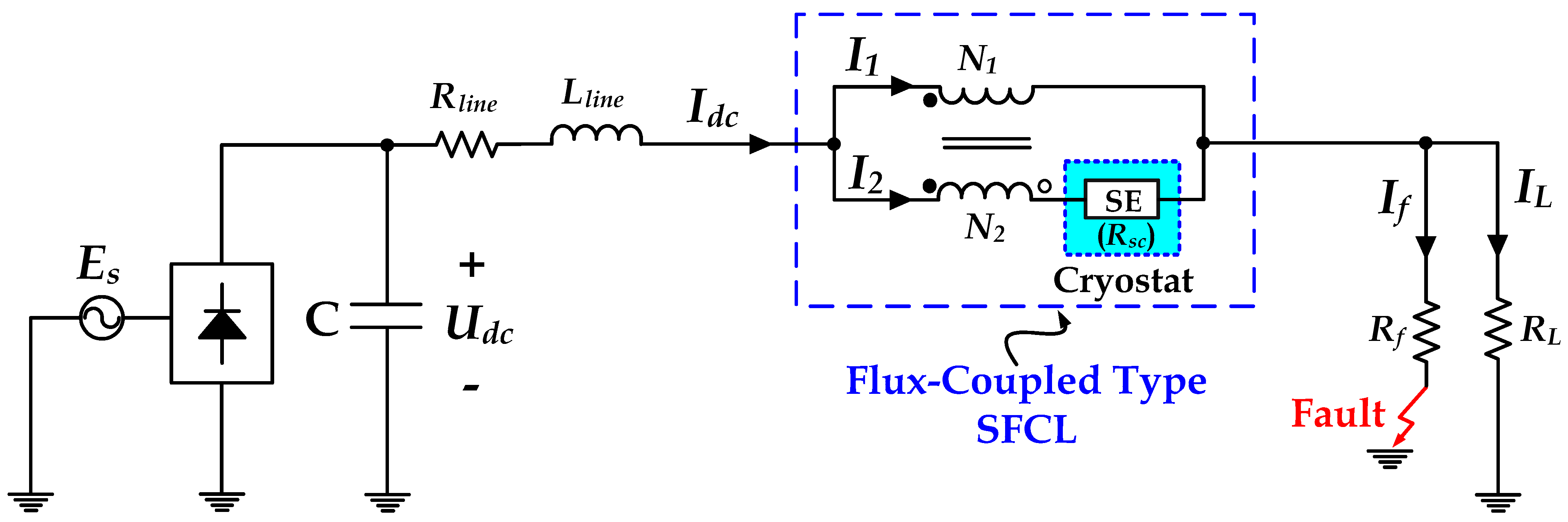
2.1. Performance of the Flux-Coupled Type SFCL in a DC Side Short Circuit Fault
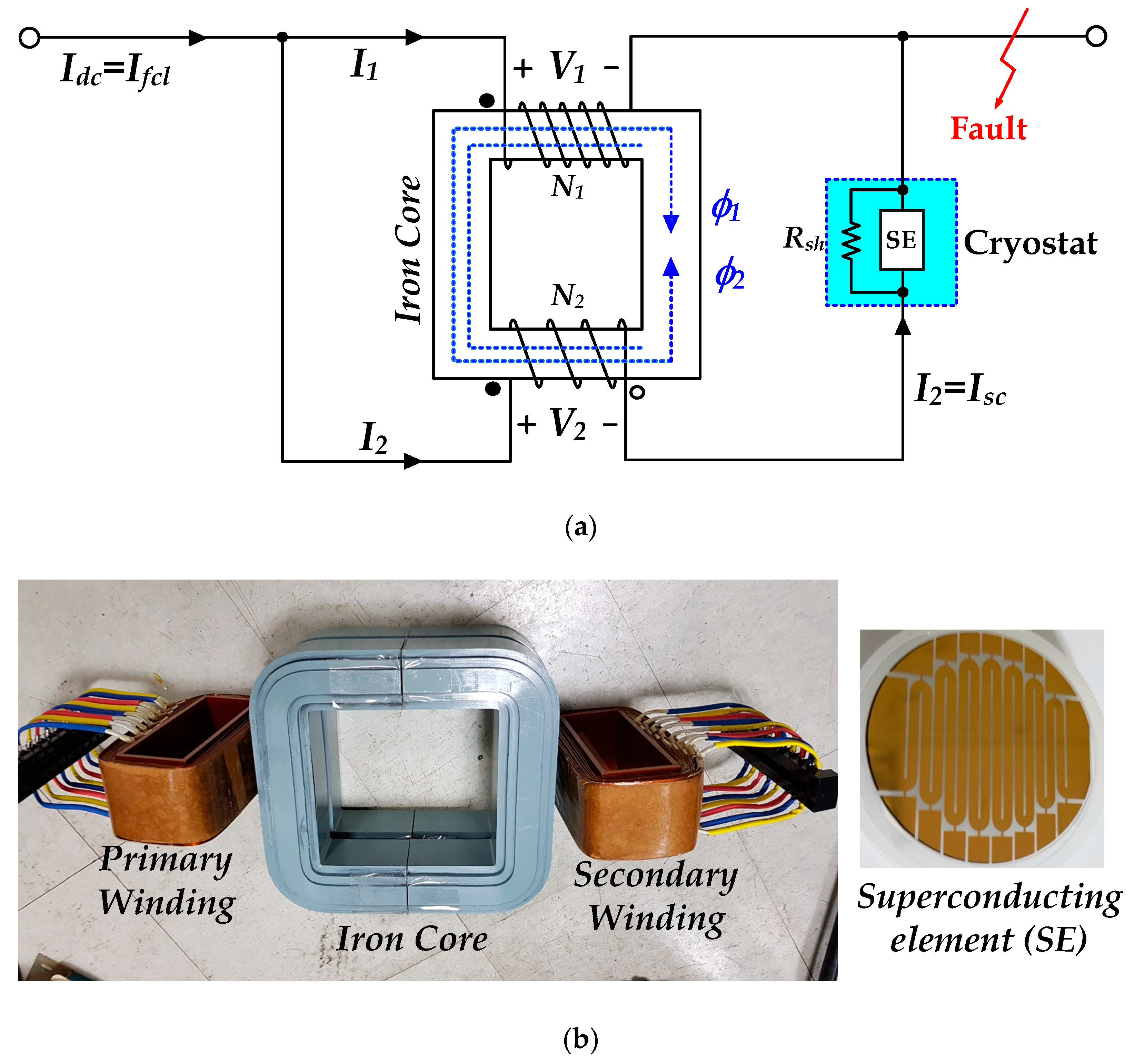
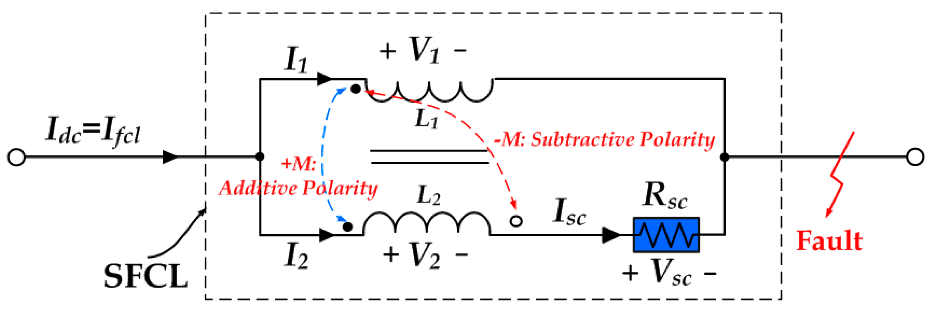
2.2. Operational Principles and Equivalent Circuit Analysis
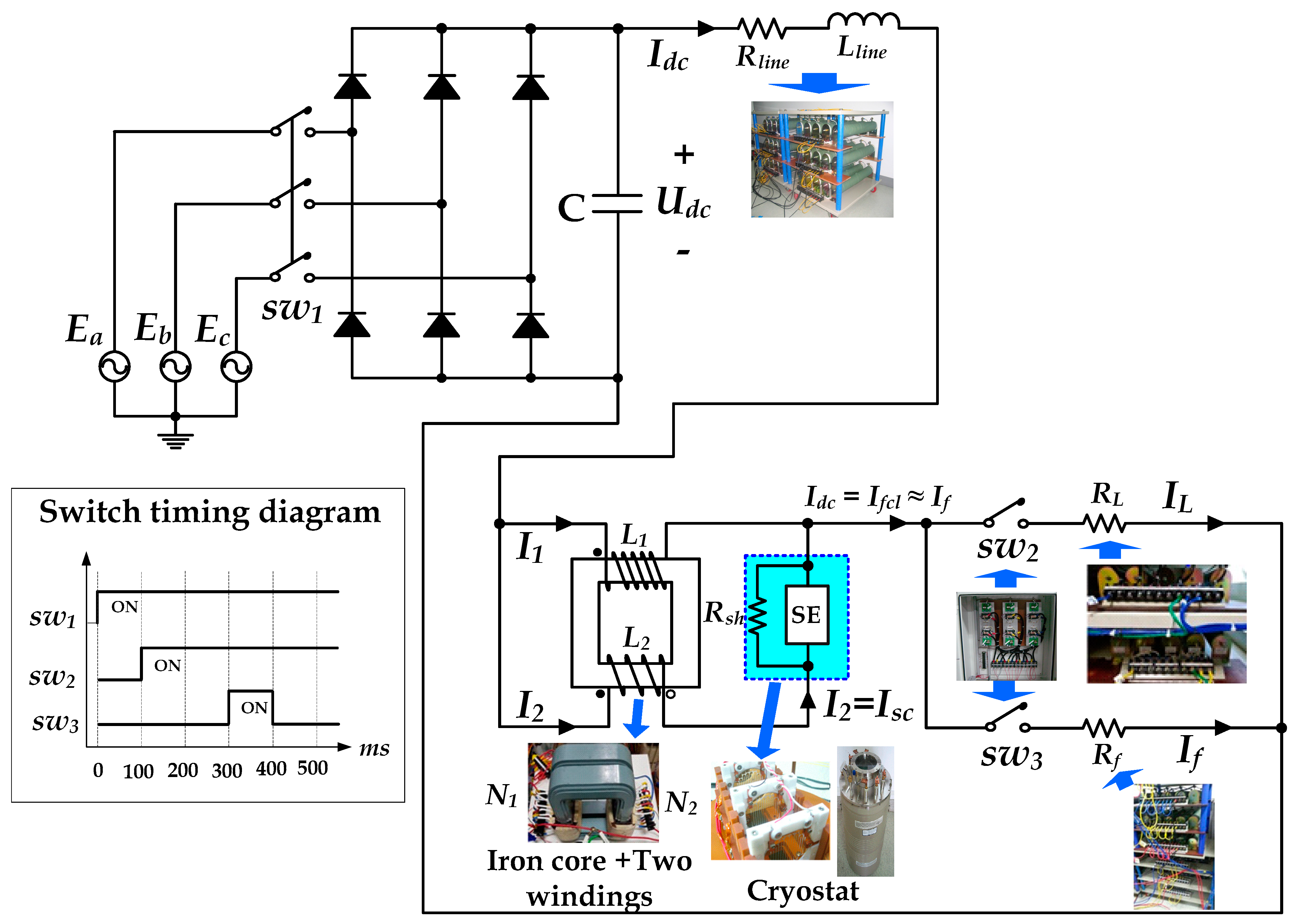
2.3. Experimental Design and Methods
3. Experimental Results
4. Conclusions
Author Contributions
Funding
Institutional Review Board Statement
Informed Consent Statement
Data Availability Statement
Conflicts of Interest
References
- Alam, M.S.; Abido, M.A.Y.; El-Amin, I. Fault current limiters in power systems: A comprehensive review. Energies 2018, 11, 1025. [Google Scholar] [CrossRef]
- Park, D.K.; Chang, K.S.; Yang, S.E.; Kim, Y.J.; Ahn, M.C.; Yoon, Y.S.; Kim, H.M.; Park, J.W.; Ko, T.K. Analytical and experimental studies on the hybrid fault current limiter employing asymmetric non-inductive coil and fast switch. IEEE Trans. Appl. Supercond. 2009, 19, 1896–1899. [Google Scholar] [CrossRef]
- Hyun, O.B.; Yim, S.W.; Yu, S.D.; Yang, S.E.; Kim, W.S.; Kim, H.R.; Lee, G.H.; Sim, J.; Park, K.B. Long-term operation and fault tests of a 22.9 kV hybrid SFCL in the KEPCO test grid. IEEE Trans. Appl. Supercond. 2011, 21, 21312134. [Google Scholar] [CrossRef]
- Kim, W.S.; Hyun, O.; Park, C.R.; Yim, S.W.; Yu, S.D.; Yang, S.E.; Kim, H.S.; Kim, H.R. Dynamic characteristics of a 22.9 kV hybrid SFCL for short circuit test considering a simple coordination of protection system in distribution networks. IEEE Trans. Appl. Supercond. 2012, 22, 5601404. [Google Scholar]
- Lim, S.H.; Kim, J.C. Analysis on protection coordination of protective devices with a SFCL due to the application location of a dispersed generation in a power distribution system. IEEE Trans. Appl. Supercond. 2012, 22, 5601104. [Google Scholar]
- Deng, C.H.; Zheng, F.; Chen, L.; Li, M.; Xia, P.; Li, S.; Lomg, Z.; Zhu, L.; Guo, F. Study of a modified flux-coupling-type superconducting fault current limiter for mitigating the effect of DC short circuit in a VSC-HVDC system. J. Supercond. Nov. Magn. 2015, 28, 1525–1534. [Google Scholar] [CrossRef]
- Song, W.; Pei, X.; Xi, J.; Zeng, X. A Novel Helical Superconducting Fault Current Limiter for Electric Propulsion Aircraft. IEEE Trans. Transp. Electrif. 2021. [Google Scholar] [CrossRef]
- Song, W.; Pei, X.; Xi, J.; Zeng, X.; Yazdani-Asrami, M.; Fang, X.; Fang, J.; Jiang, Z. AC losses in noninductive SFCL solenoidal coils wound by parallel conductors. IEEE Trans. Appl. Supercond. 2020, 30, 5602509. [Google Scholar] [CrossRef]
- Yazdani-Asrami, M.; Staines, M.; Sidorov, G.; Eieher, A. Heat transfer and recovery performance enhancement of metal and superconducting tapes under high current pulses for improving fault current-limiting behavior of HTS transformers. Supercon. Sci. Techno. 2020, 33, 095014. [Google Scholar] [CrossRef]
- Yazdani-Asrami, M.; Staines, M.; Sidorov, G.; Davies, M.; Bailey, J.; Allpress, N.; Glasson, N.; Gholamian, S.A. Fault current limiting HTS transformer with extended fault withstand time. Supercon. Sci. Techno. 2019, 32, 035006. [Google Scholar] [CrossRef]
- Hyun, O.B. Brief review of the field test and application of a superconducting fault current limiter. Prog. Supercond. Cryog. 2017, 19, 1–11. [Google Scholar]
- Lee, H.Y. A Study on Fault Protection Scheme Using Fault Current Limiter and Circuit Breaker Considering Fault Current Characteristics of Voltage Source Converter HVDC System. Ph.D. Thesis, Hanyang Unversity, Seoul, Korea, 2020; pp. 1–172. [Google Scholar]
- Franck, C.M. HVDC circuit breakers: A review identifying future research needs. IEEE Trans. Power Deliv. 2011, 26, 998–1007. [Google Scholar] [CrossRef]
- Flourentzou, N.; Agelidis, V.G.; Demetriades, G.D. VSC-based HVDC power transmission systems: An overview. IEEE Trans. Power Electron. 2009, 24, 592–602. [Google Scholar] [CrossRef]
- Bucher, M.K.; Franck, C.M. Contribution of fault current sources in multi-terminal HVDC cable networks. IEEE Trans. Power Delivery 2013, 28, 1796–1803. [Google Scholar] [CrossRef]
- Hafner, J.; Jacobson, B. Proactive hybrid HVDC breakers: A key innovation for reliable HVDC grids. In Proceedings of the CIGRE The Electric Power System of the Future: Integrating Supergrids and Microgrids International Symposium, Bologna, Italy, 13–15 September 2011; pp. 1–8. [Google Scholar]
- Li, Y.; Xia, K.; Liu, W.; Li, D. Design and simulation analysis of electromagnetic repulsion mechanism. In Proceedings of the 2010 IEEE International Conference on Industrial Technology (ICIT 2010), Via del Mar, Chile, 14–17 March 2010; pp. 914–918. [Google Scholar]
- Dordizadeh, P.; Gharghabi, P.; Niayesh, K. Dynamic analysis of a fast-acting circuit breaker (Thompson) drive mechanism. J. Korean Phys. Soc. 2011, 59, 3547–3554. [Google Scholar] [CrossRef]
- Bissal, A.; Magnusson, J.; Engdahl, G. Comparison of two ultra-fast actuator concepts. IEEE Trans. Magn. 2012, 48, 3315–3318. [Google Scholar] [CrossRef]
- Chen, Y.; Liu, X.; Sheng, J.; Cai, L.; Jin, Z.; Gu, J.; An, Z.; Yang, X.; Hong, Z. Design and application of a superconducting fault current limiter in DC systems. IEEE Trans. Appl. Supercond. 2014, 24, 5601305. [Google Scholar] [CrossRef]
- Manohar, P.; Ahmed, W. Superconducting fault current limiter to mitigate the effect of DC line fault in VSC-HVDC system. In Proceedings of the 2012 International Conference on Power, Signals, Controls and Computation, Thrissur, India, 3–6 January 2012; pp. 1–6. [Google Scholar]
- Endo, M.; Hori, T.; Koyama, T.; Kaiho, K.; Yamaguchi, I.; Arai, K.; Mizoguchi, H.; Yanabu, S. Development of a superconducting fault current limiter using various high-speed circuit breakers. IET Electr. Power Appl. 2009, 3, 363–370. [Google Scholar] [CrossRef]
- Ko, S.C.; Lim, S.H.; Han, T.H. Analysis on fault current limiting and recovery characteristics of a flux-lock type SFCL with an isolated transformer. Phys. C 2012, 484, 263–266. [Google Scholar] [CrossRef]
- Lim, S.H.; Ko, S.C.; Han, T.H. Analysis on current limiting characteristics of a transformer type SFCL with two triggering current levels. Phys. C 2012, 484, 253–257. [Google Scholar] [CrossRef]
- Lim, S.H.; Kim, Y.P.; Ko, S.C. Effect of peak current limiting in series-connection SFCL with two magnetically coupled circuits using E-I core. IEEE Trans. Appl. Supercond. 2016, 26, 5600404. [Google Scholar] [CrossRef]
- Lim, S.H.; Ko, S.C. Comparison of peak current limiting in two magnetically coupled SFCLs using dual iron cores. IEEE Trans. Appl. Supercond. 2016, 26, 5600304. [Google Scholar] [CrossRef]
- Ko, S.C.; Han, T.H.; Lim, S.H. Analysis on current limiting characteristics according to the Influence of the magnetic flux for SFCL with two magnetic paths. J. Electr. Eng. Technol. 2014, 9, 1909–1913. [Google Scholar] [CrossRef]
- Ko, S.C.; Han, T.H.; Lim, S.H. Current-limiting and recovery characteristics of a flux-lock-type SFCL with two adjustable operational currents. J. Korean Phys. Soc. 2014, 65, 253–256. [Google Scholar] [CrossRef]
- Han, T.H.; Ko, S.C.; Lee, B.J.; Lim, S.H. Study on current limiting characteristics of a flux-lock type SFCL using series connected two coils with twice triggering operation. J. Electr. Eng. Technol. 2014, 9, 777–781. [Google Scholar] [CrossRef]
- Qiu, Q.; Xiao, L.; Zhang, Z.; Jing, L.; Liu, Q.; Zhang, G.; Xia, D. Design and test of 10kV/400A flux-coupling–typesuperconducting fault current limiting module. IEEE Trans. Appl. Supercond. 2018, 28, 5601806. [Google Scholar] [CrossRef]
- Li, Z.; Liang, S.; Ren, L.; Tan, X.; Xu, Y.; Tang, Y.; Li, J.; Shi, J. Application of flux-coupling-type superconducting fault current limiter on shipboard MVDC integrated power systems. IEEE Trans. Appl. Supercond. 2020, 30, 5601908. [Google Scholar] [CrossRef]
- Shu, J.; Wang, S.; Liu, T.; Jiao, N.; Wang, Y. A novel current-limiting circuit based on resistive-type SFCL for fault in DC power system. Microelectron. Reliab. 2018, 88, 1201–1205. [Google Scholar] [CrossRef]
- Lee, J.G.; Khan, U.A.; Hwang, J.S.; Seong, J.K.; Shin, W.J.; Park, B.B.; Lee, B.W. Assessment on the influence of resistive superconducting fault current limiter in VSC-HVDC system. Phys. C. 2014, 504, 163–166. [Google Scholar] [CrossRef]
- Chen, L.; Zhang, X.; Qin, Y.; Chen, H.; Shen, Q.S.; Xu, Y.; Ren, L.; Tang, Y. Application and design of a resistive-type superconducting fault current limiter for efficient protection of a DC microgrid. IEEE Trans. Appl. Supercond. 2019, 29, 5600607. [Google Scholar] [CrossRef]
- Kim, H.R.; Choi, H.S.; Lim, H.R.; Kim, I.S.; Hyun, O.B. Initial quench development in uniform Au/Y-Ba-Cu-O thin films. IEEE Trans. Appl. Supercond. 2001, 11, 2414–2417. [Google Scholar]
- Choi, H.S.; Hyun, O.B.; Kim, H.R.; Park, K.B. Switching properties of a hybrid type superconducting fault current limiter using YBCO stripes. IEEE Trans. Appl. Supercond. 2002, 14, 1833–1838. [Google Scholar] [CrossRef]


| Specification | Value | Unit | |
|---|---|---|---|
| Power supply | AC voltage (Eab) | 80 | Vrms |
| DC voltage (Udc) | 117 | Vdc | |
| Filter capacitor | Capacitor (C) | 10,200 | μF |
| Line impedance | Line resistor (Rline) Line inductance (Lline) | 0.42 0.18 | Ω mH |
| Load | Load resistor (RL) | 10 | Ω |
| Fault fire | Fault resistor (Rf) | 1.5 | Ω |
| Inductor in the SFCL | Inductance 1 (L1) Inductance 2 (L2) | 60.9 1.3 | mH mH |
| Superconducting element (SE) | Material Critical temperature (Tc) Critical Current (Ic) Shunt resistor (Rsh) | YBCO 87 27 1.5 | Thin film K A Ω |
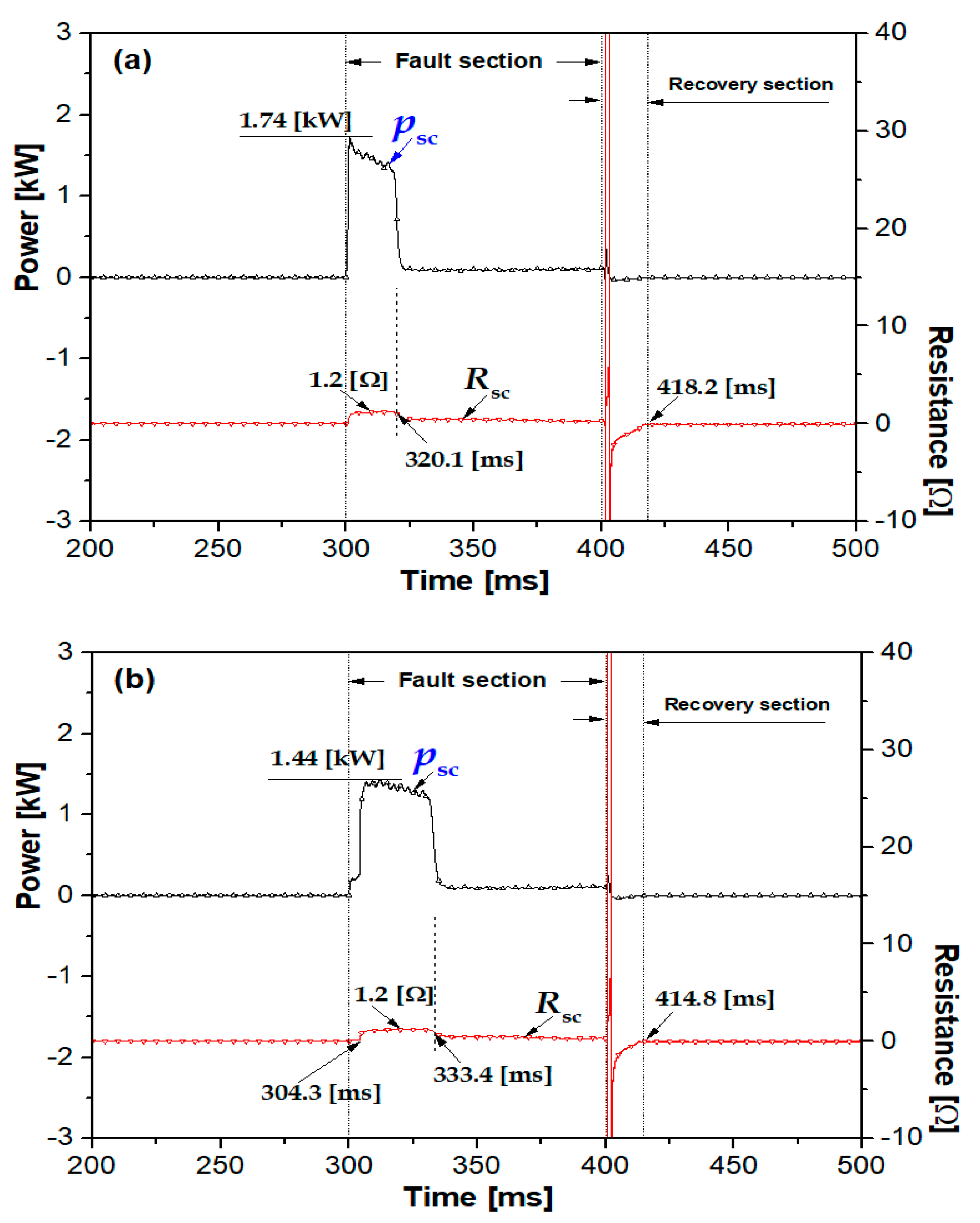
| Recovery Time | In case of additive wiring | 18.2 | ms |
| In case of subtractive wiring | 14.8 | Ms | |
Publisher’s Note: MDPI stays neutral with regard to jurisdictional claims in published maps and institutional affiliations. |
© 2021 by the authors. Licensee MDPI, Basel, Switzerland. This article is an open access article distributed under the terms and conditions of the Creative Commons Attribution (CC BY) license (http://creativecommons.org/licenses/by/4.0/).
Share and Cite
Kim, Y.-P.; Ko, S.-C. DC Current Limiting Characteristics of Flux-Coupled Type SFCL Using Superconducting Element Connected in Parallel in a DC System. Energies 2021, 14, 1096. https://doi.org/10.3390/en14041096
Kim Y-P, Ko S-C. DC Current Limiting Characteristics of Flux-Coupled Type SFCL Using Superconducting Element Connected in Parallel in a DC System. Energies. 2021; 14(4):1096. https://doi.org/10.3390/en14041096
Chicago/Turabian StyleKim, Young-Pil, and Seok-Cheol Ko. 2021. "DC Current Limiting Characteristics of Flux-Coupled Type SFCL Using Superconducting Element Connected in Parallel in a DC System" Energies 14, no. 4: 1096. https://doi.org/10.3390/en14041096
APA StyleKim, Y.-P., & Ko, S.-C. (2021). DC Current Limiting Characteristics of Flux-Coupled Type SFCL Using Superconducting Element Connected in Parallel in a DC System. Energies, 14(4), 1096. https://doi.org/10.3390/en14041096