1. Introduction
A detailed understanding of reservoir and caprock lithologies is important for any CO2-EOR project and is crucial for carbon storage projects. Characterization entails developing knowledge of the reservoir from the pore to the field scale. Such knowledge must include understanding of the various lithofacies (how they were formed and what diagenetic processes have they undergone), understanding of depositional systems that dictate reservoir architecture and heterogeneity, and an understanding of the relationships between rock composition and resultant geomechanical and flow properties that feed into the reservoir models used for simulation and prediction of reservoir behavior.
Most reservoir studies of Morrow reservoirs in the Anadarko basin have focused on sandstones because of their importance in conventional oil production. Although this study examines the sandstones within the field, an important feature of our work is detailed characterization of both the overlying and underlying confining layers, as these are critical to containment of injected CO2.
The significance of this paper is twofold: we present a synthesis of extensive work by several researchers that has not previously been published, and we provide a brief view of some of the rich dataset that we have collected for the project, which will be archived with public repositories at the conclusion of the project.
2. Materials and Methods
A variety of datasets were used for the work presented here. Cores from several wells, including characterization wells drilled specifically for this project, were described and analyzed. Cored intervals from five wells on the western side of the field (8-5, 9-8, 13-10, 13-14, and 13-10A) and three from the eastern side of the field (32-2, 32-6, and 32-8), were described (
Figure 1). Wells 13-10A, 13-14, and 32-8 were drilled as characterization wells for this study, and extensive datasets were collected from them. No destructive testing was allowed on the legacy cores, so observations were limited to visual inspection only. Limited core was available for each of the legacy wells and almost none from non-reservoir intervals. Approximately 250 ft of core was obtained from each of the new characterization wells. Cored intervals include the entire Morrow B reservoir interval, as well as Morrow shale that underlies and overlies the Morrow B, the B1 sandstone interval, and the Thirteen Finger limestone that makes up the remainder of the primary seal.
The core descriptions were the basis for formation identification, development of detailed stratigraphic columns, facies classification, and interpretation of depositional environment and sequence stratigraphy. Samples from the three characterization wells were used for measurement of porosity, permeability, geomechanical properties, petrographic analysis, X-ray diffraction (XRD), stable isotope and electron microprobe studies for characterization of rock composition, textural relationships, diagenetic alteration, and studies of pore structure and networks. Well logs including borehole imaging logs were run in characterization wells to aid in interpretation of features such as fractures, lithology changes, and orientation for interpretation of bedding and sediment flow direction. Samples were also taken for U–Pb and 40Ar/39Ar dating of zircon and muscovite to understand regional sediment routing and provide new constraints for the age of the Morrow B. Additional data included a small set of thin sections and core plug porosity and permeability data from older wells in the field.
Formation-top data and wire-line logs wells in a 95 mile2 area around FWU were made available from the field operator. An advanced suite of logs for the three characterization wells was also available. Formation top-picks in legacy wells were checked and standardized with respect to the newly-acquired advanced logs, and all well data were compiled into Schlumberger’s Petrel software program. Correlation of formation tops allowed construction of formation surfaces and thickness maps. Combining well and log data with 3D seismic data for FWU allowed creation of a detailed and more accurate model of this reservoir.
3. Results and Discussion
The processes used during this project are now used as a blueprint for other carbon sequestration characterization efforts that have been initiated elsewhere within the western USA. Results of the work include detailed descriptions of cores and thin sections, field maps, and cross-sections that have been used to establish a robust and increasingly sophisticated geological model for the field [
1]
3.1. Geologic Setting
3.1.1. Regional Stratigraphic Framework
The Farnsworth Field Unit (FWU) is currently the site of a large-scale carbon dioxide (CO
2) storage and enhanced oil recovery (EOR) project. The field is located in the northwestern part of the Texas panhandle in Ochiltree County, near the town of Perryton. The FWU is situated within the northwestern shelf of the Anadarko basin and is one of many reservoirs that produce from a Pennsylvanian sequence of alternating mudstone and sandstone intervals [
2]. Production at FWU is from the operationally-named Morrow B sandstone—the uppermost sandstone encountered below the Thirteen Finger limestone (
Figure 2). The Morrow B sandstone has been previously interpreted to be Morrowan in age-based lithostratigraphic correlation and biostratigraphy of overlying units [
3]. Analysis of fusulinids and references therein] and conodonts [
4] recovered from the Thirteen Finger limestone in southeast Colorado and Kansas suggests an Atokan age that provides a minimum biostratigraphic constraint for the Morrow B. However, Hollingworth et al. [
5] report a new U–Pb detrital zircon maximum depositional age of 310.9 ± 4.9 Ma, suggesting that the age of the Morrow B is closer to the Atokan–Desmoinesian boundary. This also has implications for the age of the primary caprock intervals at FWU, the upper Morrow shale, previously interpreted as Morrowan in age, and the Thirteen Finger limestone, previously interpreted as Atokan in age [
3]. Additional geochronologic and biostratigraphic work is necessary to resolve the apparent conflict between depositional ages, but in this study, we rely on the existing biostratigraphic framework [
3,
6]. The Thirteen Finger limestone is an informal name for a series of approximately thirteen predominantly limestone intervals that are intercalated with mudstone and coal layers. Similar Morrowan deposits in the Anadarko basin throughout the Texas and Oklahoma panhandles, southeastern Colorado, and western Kansas, have been studied extensively due to their importance as oil-producing reservoirs [
7,
8,
9,
10,
11,
12]. Overlying rocks have received less attention but are a potential target for unconventional production elsewhere in the basin [
4]. Our interest in the Thirteen Finger interval is primarily as a seal and caprock for CO
2 storage.
The Morrowan and Atokan intervals were deposited during the early to middle Pennsylvanian [
13]. During this time, the African, South American, and Antarctic cratons were coalescing in the southern latitudes to form the Gondwanan land mass [
14,
15]. This coalescence created a setting in which large ice sheets grew and receded on time scales corresponding to orbital Milankovitch cycles [
16,
17]. The fluctuations in ice volume in turn caused global sea levels to rise and fall, creating the rapid facies changes typical of Pennsylvanian and Permian stratigraphy [
8,
9,
18]. During this period, North America was at equatorial latitudes and drifting northward, causing the area to transition from humid to subhumid climates during the Pennsylvanian [
19]. The collision of the North American and Gondwanan, and/or activity on the western and southwestern Laurentian, margins drove deformation across southwestern and central Laurentia [
20,
21,
22,
23,
24]. Uplift associated with this deformation shed substantial volumes of clastic sediment to adjacent basins (e.g., [
12,
25,
26,
27,
28]). The subsequent filling of these basins is responsible for most of the overlying rock column at FWU. Overlying strata includes upper Pennsylvanian through the middle Permian shales and limestones, with lesser amounts of dolomite, sandstone, and evaporites [
12,
18].
3.1.2. Tectonic Setting
The FWU is located on the northwest shelf of the Anadarko basin (
Figure 3). From FWU, the basin plunges to the southeast where it reaches depths of over 40,000 ft (12,192 m) adjacent to the Amarillo–Wichita Uplift [
29]. The Anadarko basin formed as the result of flexural loading of the lithosphere by the adjacent Amarillo–Wichita Uplift [
23,
29,
30]. The Amarillo–Wichita Uplift formed as the result of reactivation of basement faults in a region known as the Southern Oklahoma Aulacogen that are associated with the Neoproterozoic breakup of the Rodinian supercontinent [
29,
31] However, the tectonic drivers for the uplift on the Amarillo–Wichita are the subject of debate. Most interpretations attribute uplift to either collision between Gondwana and Laurentia [
20,
23,
32] or stress generated along the southwest margin of Laurentia [
21,
24]. Positive features that might have influenced deposition within the region include the Ancestral Front Range to the northwest [
33], the Central Kansas uplift to the northeast [
34], and the Amarillo–Wichita uplift to the south [
35,
36,
37].
Anadarko basin subsidence and Amarillo–Wichita basement uplift were approximately synchronous, beginning in the Chesterian–Morrowan and continuing through the Pennsylvanian and ending in the Wolfcampian [
21]. Maximum rates of subsidence occurred during Morrowan to Atokan times [
12,
29,
35]. Tectonic activity slowed after the Atokan and the region was quiescent by the end of the Pennsylvanian. The uplifts and associated basins combined with the climate at time of deposition set the stage for the stratigraphic sequence seen in FWU cores.
3.1.3. Depositional Environment
Interpretations of the depositional setting of the Morrow B have evolved over the decades. Many previous workers have recognized upper Morrowan sandstones in the northwestern Anadarko basin as fluvial deposits [
2,
7,
8,
9,
10,
36,
40,
41,
42,
43,
44,
45,
46]. Early regional depositional and stratigraphic models were developed using core and electric log data from wells across the Anadarko basin [
3,
40,
41,
47]. Swanson [
40] proposed relatively synchronous deposition of sands and muds as different parts of the same fluvial and deltaic systems. In contrast, Sonnenberg [
41,
48] proposed an incised valley-fill (IVF) model to describe Morrowan sandstones. In the Sonnenberg IVF model, sand distribution is confined within the walls of previously incised valleys. In this model, lateral changes from sandstone to mudstone are interpreted to mark the edges of those paleovalleys. A major difference between this and the earlier-proposed Swanson model is that in the Sonnenberg model, the laterally equivalent mudstones that encase the reservoir sands were deposited under marine conditions during the previous high-stand system tract (HST) and are older than the IVF deposits. Our work at FWU refines the IVF depositional model, and provides a sequence stratigraphic framework for the reservoir and seal (see below).
In contrast to the predominantly fluvial to estuarine environment proposed for the Morrow sandstones and shales, the overlying Atokan Thirteen Finger limestone was deposited in an estuarine to marginal marine environment representing several cycles of transgression and regression during its deposition [
48]. The main lithologies include mudstone, interlayered with limestone (cementstone), and some coal [
49].
3.2. Lithofacies
3.2.1. Log Identification
In FWU, the Morrow B reservoir is identified in logs by a characteristic blocky shape created by low gamma ray (GR) values (
Figure 2), or negative deviations in spontaneous potential (SP) measurements, both associated with clean reservoir sand [
2,
3,
45]. The Morrow B reservoir is the first blocky, low-GR signature below the Thirteen Finger limestone [
36]. If a sand signature is present below the Morrow B it is termed the Morrow B1, and Morrow-D if there is a third. The Morrow shale is those parts of the GR curve having consistently high GR values immediately above and below the Morrow B reservoir (
Figure 2). These intercalated sand and shale packages are all within the upper Morrow, an informal subdivision used through many parts of the Anadarko basin [
48].
The Thirteen Finger limestone has a distinctive wireline log signature showing 12–17 sharp fluctuations in the GR curve (
Figure 2). Spikes of low gamma ray readings correspond to limestone beds that give the unit its name, and the intervening GR highs are associated with mudstone or shale beds. The base of the Thirteen Finger limestone is picked at the top of the second low GR spike above the Morrow B reservoir. This corresponds to a coal bed at the top that is a reliable regional stratigraphic marker for the top of the uppermost Morrow shale. The top of the Thirteen Finger limestone is less uniformly designated, but for this project was chosen using the same criteria as geologists from the industry partner [
50]. The top of the Thirteen Finger is picked from the GR curve at a prominent low GR spike, above which are relatively high GR values, consistent for 5–15 ft (1.5–4.5 m), above which the next decrease in GR is less dramatic, and finally above which are two prominent GR lows associated with limestone beds of the lower Cherokee Group (
Figure 2).
3.2.2. Core Description
Core descriptions are based on works of Gallagher [
46] and Rose-Coss [
49]. Gallagher’s descriptions used observations of legacy cores (
Figure 1) that were made available for viewing, and core from well 13-10A, the first of three characterization wells drilled during the project (
Figure 1). Gallagher’s work focused strictly on the Morrow B and described the four principal lithofacies encountered in core: fine-grained sandstone, coarse-grained sandstone, and conglomerate. Rose-Coss [
49] was only able to view photographs of the legacy core, but had access to all three cores for wells drilled for this project, which included not only the Morrow reservoir rock but portions of underlying Morrow shale, as well as overlying Morrow sandstone, Morrow shale, Thirteen Finger, and Marmaton units. Rose-Coss [
49] described the entire cored interval of the Morrow sandstone, as well as the overlying Morrow shale and Atokan Thirteen Finger caprock intervals, subdividing the section into 10 different lithofacies based on composition, sedimentary structures, grain size, and color (
Table 1,
Table 2 and
Table 3). Miall’s 1985 classification [
51] was used for the Morrow B sandstone, and the classification of Lazar et al. [
52] for mudstones in the overlying Morrow shale caprock. Detailed core descriptions and photographs are found in Gallagher [
46] for the reservoir intervals in legacy wells and well 13-10A, and Rose-Coss [
49] for full core descriptions of the three characterization wells: 13-10A, 13-14, and 32-8.
Figure 4 presents a generalized paleoenvironment reconstruction based on lithofacies noted in cores for the Morrow B and B1 sandstone at FWU, along with typical examples of each. Similar features and sequences of lithofacies were noted in all the cores examined, with small variations in thicknesses, clast types, and sedimentary structures. The general sequence of lithofacies for the Morrow noted in all FWU cores, from deeper to shallower, is marine mudstone, channel lag conglomerate, fluvial coarse-grained sandstone, estuarine fine-grained sandstone, and marine mudstone.
Morrow Sandstone
The base of the Morrow B sandstone interval is an abrupt, irregular contact above underlying Morrow shale. The lowest sandstone interval noted in many of the cores is a highly-indurated calcite-cemented basal lag conglomerate that ranges in thickness from 0.3–0.9 m. In most cores, the conglomerate is clast-supported with subrounded clasts, primarily composed of quartzite and granitic rock fragments, as well as some mudstone and siderite concretion clasts [
52]. Maximum clast size is 5 cm; however, average clast size is 1–2 cm. Well 13-10A contains ~15 cm of matrix-supported conglomerate (paraconglomerate) approximately 20 cm above the contact between the Morrow shale and the basal conglomerate (
Figure 5). The conglomerate is made up of a lower coarse-grained light gray sandstone matrix surrounding larger clasts, many elongate, that are typically subrounded, 2-mm to 3-cm long, and consist of mudstone, sandstone, and pyritized rip-up clasts. The matrix-supported conglomerate was not noted in the other cored wells. The basal conglomerate section in well 13-14 does not contain mudstone clasts and is finer-grained than in the other two wells. Conglomerates tend to be highly-cemented with a variety of carbonate cements, including calcite and ankerite.
Basal conglomerates grade upwards into an overlying coarse-grained sandstone facies. In all characterization cores there is a very thin (<2.5-cm thick) coal layer 15 to 20 cm above the conglomerate section. The remainder of the Morrow B interval is composed of brown to dark brown, moderately to poorly sorted, subrounded to subangular, very coarse sands and fine gravels. The uppermost portion of the Morrow B sandstone is generally finer-grained, ranging from fine to upper-medium sand.
Primary depositional textures and structures are similar in most of the cores. Using Miall’s classification for fluvial sediments [
51], lithofacies are first described by grain size, and then bedding. Within the Morrow B, grain size is described as either gravel (G) or sand (S), and bedding either massive (m), laminated (l), or irregular (i). Thus, an interval of predominantly massive gravels is denoted Gm, and an interval of laminated gravels is Gl. Lithofacies codes and descriptions for Morrow B and B1 sandstones are noted in
Table 1.
In FWU cores, the thickness of sandstone intervals with massive, laminated, or irregular bedding ranges from 15–61 cm [
49]. Laminated intervals are planar to low-angle with 2–10-cm thick fining or coarsening upward sequences. Clay seams, thin mudstone interbeds, and stylolites were noted in most wells (e.g.,
Figure 5, depth 7733 ft.) and examples in [
46,
49]. Sandstones are mostly fine- to coarse-grained sandstone and exhibit fining upward sequences. Rounded mudstone intraclasts occur locally, some with desiccation cracks. A fining upward sequence 15–46-cm thick caps the Morrow B sandstone section, however internal grain size sequence intervals do not appear to repeat in any recognizable pattern [
49]. Some overall variation in grain size was noted through the field [
46]. The sandstone facies in wells 9-8 (far west side) and 32-8 (east side) is finer-grained than observed in other wells. Well 32-6 contains cross-bedding that exhibits considerable variation in grain size between laminae, alternating in size between coarse sand and conglomerate; such well-defined bedding was not noted in any of the other cores examined [
46].
Morrow Shale
The Morrow B (and B1, where present) sandstones are encased above and below by shales. Contacts with shale both below and above the sandstone are sharp and irregular (
Figure 5). Morrow shale facies are described in
Table 2. Only a few feet of underlying shale were cored, so this work describes the shale sequence encountered in the shale overlying the Morrow B sandstone, except as noted. Similar facies are seen in the underlying shale section. The overlying shale section starts above a fining-upward sequence at the top of the Morrow B sandstone (
Figure 6 and [
46]). The Morrow shale generally fines upwards in a series of thin beds 2.5–5-cm thick that alternate between upper fine sands and fine to medium muds. Sand content decreases upwards through the section. The lowest lithofacies of the Morrow shale (facies gbM) is olive to grey, weakly to moderately bioturbated, with either massive bedding, or discontinuous parallel and non-parallel laminations. The rock is friable, argillaceous fine- to medium-grained mud, with minor organic and detrital content. Facies gbM ranges from 4.3–6.7-m thick in the cored wells. This facies terminates abruptly in the black, fissile-laminated, mudstone facies blM. Facies blM is argillaceous and siliceous, fine to coarse muds with minor organic content. Interspersed with the mudstone are intervals containing fossil hash beds and scattered pyritized shells, sparse calcite concretions and rare pyrite nodules. Continuing up-section, facies blM transitions to a greenish grey, friable calcareous mudstone, facies cM, topped by a thin coal layer. Although facies cM closely resembles facies gbM seen lower in the section, it has a greater amount of organic and calcareous content, as compared to facies gbM. Facies cM is the highest stratigraphic interval of the upper Morrow shale and was not noted in the interval of Morrow shale below the Morrow B sandstone, which is predominately facies blM with minor gbM.
The uppermost part of the Morrow shale has a distinctive sequence of facies that is noted in all of the characterization wells (
Figure 6). Approximately 45 cm below the contact with the Thirteen Finger limestone, there is a 2.5–7.5-cm thick section of rock that is smooth and well-indurated with irregular to rounded bounding surfaces. This distinct interval contains a diverse microfaunal assemblage including foraminifera, gastropods, ostracods, bryozoans, mollusks, and fish scales (
Figure 6, and [
44] Figure 30). Other noteworthy aspects within the short interval include phosphate nodules and possible dewatering structures. Above the well-indurated section is another 30–45 cm of facies cM. The facies terminates at a sharp contact with an 18-cm thick coal bed. The coal is followed by a 15–20-cm grey, calcite-cemented layer (appearing as a concretion in well 13-10A), and then a 5-cm, highly burrowed interval. The burrowed interval is topped by another 5–7.7-cm fossil hash bed (
Figure 7), then a black carbonaceous mudstone (bcM) that is one of the signature facies of the Thirteen Finger limestone [
49].
Thirteen Finger Limestone
The Thirteen Finger limestone is not a single limestone bed, but a series of intercalated black, carbonaceous mudstones (bcM), coals, and limestone intervals that are primarily diagenetic in origin (cC) (
Figure 7 and
Table 3). Individual limestone beds are 10–60 cm in thickness and are separated by 2–10-cm mudstone intervals. The limestones are clustered in 0.2–2.7-m thick intervals, separated by 0.3–1.2-m mudstone beds. The entire Thirteen Finger interval is 39.6-m thick, with approximately 41% of the thickness composed of mudstone, 4% coal, and 46% is limestone. The number of limestone and mudstone beds varies from well to well; in well 13-10A, 60-70 individual limestone beds were counted [
49].
Limestone beds are grey to dull white and are dominated by diagenetic calcite and dolomite cements with sparse sponge spicules and pyrite framboids [
54]. This facies is more accurately described as a cementstone; consequently, the limestone beds in the Thirteen Finger limestone are classified herein as facies cC. In core, facies cC may have gradational or sharp contacts with mudstone facies and is predominantly massively bedded with only faint signs of stratification. Some cC sections have irregular rounded upper and lower contacts, and are laterally discontinuous, so are concretion-like in appearance. Mineralized fractures are present locally. The mudstone, facies bcM, is black to grey, massive and smooth in some sections, laminated and fissile in others. Some layers are poorly consolidated and broken, in part due to mechanical fracturing during coring, whereas others are well-indurated. Facies bcM contains abundant clays and authigenic calcite, dolomite, and phosphate. Sedimentary features include pyrite nodules, fossil hash, bioturbation, and bedding parallel fibrous veins (
Figure 8) referred to as “calcite beef” [
55,
56]. Coal beds within the Thirteen Finger limestone are between 0.15–0.6-m thick and separated by 3–6-m intervals. Total organic carbon (TOC) within the Thirteen Finger limestone facies is high, with one measurement at 49.0% within the coal at the base of the formation and another at 10.7% [
49].
3.2.3. Petrographic Analysis and Interpretation
Details of petrographic analysis for FWU cored samples examined in this project, including data and extensive photomicrographs, can be found in Gallagher [
46], Cather [
57,
58], Cather and Cather [
54], Rose-Coss [
49], and Trujillo [
59]. A summary is included here to support the interpretations of facies model and sequence stratigraphy. Upper Morrow sandstones are mostly subarkosic, with an average framework grain composition of 78% quartz, 7% feldspar, and 15% rock fragments. Feldspars are predominately alkali feldspar. Grain and clast types are interpreted to indicate derivation primarily from granitic sources [
54]. The relatively coarse grain size of these sandstones suggests proximal sources, probably in the Sierra Grande uplift to the west or the Amarillo–Wichita uplift to the south. Silicic volcanic sources were a nearly ubiquitous, but minor, contributor to most of the studied sandstones. Cambrian and Mesoproterozoic rhyolite is common in the Amarillo–Wichita uplift region, and these rocks are interpreted to have been a source for silicic volcanic grains in the Morrow B [
60,
61]. Recycled sedimentary detritus is a minor component of about half of the samples; much of this may be intraformational. No vertical trends in the abundance of detrital components are apparent [
54]. Composition of the mudstones both within the Morrow shale and the mudstone beds of the Thirteen Finger limestone is predominately illite/smectite clays with trace to minor amounts of quartz. Mudstones may contain a significant amount of carbonate, mainly dolomite, and the amount of carbonate observed in core and in log analyses increases up section from the base of the Morrow shale that overlies the Morrow B sandstone [
62]. The limestones within the Thirteen Finger limestone are almost pure calcium carbonate, primarily diagenetic calcite, and can be described as cementstones [
49].
Documenting the diagenetic processes observed within FWU rocks is important to the characterization of the reservoir and seal for a variety of reasons. Discussions of diagenesis and paragenetic sequence can be found in Gallagher [
46] (Figure 41) and [
54]. Within the Morrow B, diagenetic processes such as precipitation of cements and clays, and dissolution of various mineral phases appear to exert the greatest controls on petrophysical properties, and they overprint primary depositional processes [
46,
54]. Authigenic cements within Morrow B reservoir sandstone include quartz and feldspar overgrowths, calcite in the form of poikilotopic or sparry cement that fills pores and often replaces feldspar grains, siderite (sphaerosiderite), dolomite and ankerite, kaolinite, illite and other clay minerals, and residual oil or bitumen [
54]. Pyrite occurs both as crystals and nodules within the mudstones, and as replacement of fossils.
Diagenetic processes within the Thirteen Finger limestone and upper Morrow shale influence mechanical properties and seal behavior. Mechanical testing has shown the cementstones of the Thirteen Finger are the most brittle rocks in the primary seal and the most likely to fracture under stress; therefore, they were a focus of more detailed study [
59]. Although most of the cementstones encountered within the cores appear to be continuous through the core diameter, several cemented zones were also noted with rounded or cigar-shaped morphology indicative of concretions, thus raising questions concerning the lateral extent of the cementstones. Isotopic analysis to determine the geometry of the cementstones (following the approach of Klein et al. [
63]) was inconclusive, so for purposes of modeling and caprock simulation studies, the cementstones are currently treated as continuous layers [
59].
3.2.4. Paragenesis
Morrow B—The paragenetic sequence for the Upper Morrow sandstones is presented in
Figure 9. Rare early cements, including pyrite and phosphate, were noted in a few thin sections, but siderite and calcite are the most prevalent early cements. Siderite occurs as sphaerosiderite, commonly associated with pedogenesis, and individual or clusters of small rhombic crystals. All appear to have precipitated before significant compaction, and a high Fe/Mg ratio in some microprobe analyses indicate that formation likely occurred in a freshwater environment. In some samples, multiple stages of siderite with differing Fe/Mg ratios may document changing pore water chemistry resulting from marine transgression [
46,
64,
65]. Poikilotopic calcite was precipitated early in the diagenetic sequence, filling primary porosity and replacing feldspars [
54]. Extensive calcite cementation prevented significant compaction in some intervals but occludes almost all porosity, creating some of the lowest permeability intervals within the Morrow B [
49].
Feldspar alteration and precipitation of authigenic clay, predominantly kaolinite, are important within the Morrow B, as these processes probably had the greatest effect on the evolution of the porosity and permeability trends seen in the reservoir. Microprobe and X-ray diffraction analyses suggest that most detrital feldspar has been replaced by diagenetic albite [
53]. Grains are commonly vacuolized, kaolinized, and/or sericitized. In many samples, wholesale dissolution of feldspar can create large pore spaces, or pore space that has subsequently been partially to completely filled with kaolinite. It is clear from the presence of many delicate skeletal feldspars and large kaolinite-filled pores that most feldspar dissolution and replacement occurred after compaction. Other authigenic clays such as illite/smectite and chlorite were noted but were not significant components of any of the samples examined. Gypsum cement is also a rare constituent. Its position in the paragenetic sequence is unclear, but seems to be associated with the oxidation of pyrite. Petrographic evidence [
54] shows it follows at least one stage of calcite precipitation in fracture fills. The studied samples are from below the water table in a reduced, petroleum-bearing stratigraphic interval, so oxidation of pyrite to form gypsum late in the paragenetic sequence is unlikely. The degree of compaction within Morrow B sands varies from very little in samples that have extensive early cementation to significant in a few samples where stylolites and long, concavo-convex, or sutured grain contacts are noted. Hydrocarbon migration appears to be the last major diagenetic event affecting the Morrow B sandstone, although an additional, relatively minor episode of feldspar dissolution after hydrocarbon migration was noted in a few thin sections [
46,
54,
57].
Less emphasis was placed on study of paragenetic sequence in the Morrow shale and Thirteen Finger limestone. For the purposes of this project, the greatest emphasis was placed on the effect of diagenetic events on mechanical properties, and the overall effectiveness of the caprock as a seal for the injected CO
2. Several lines of investigation were pursued, including fracture analysis, geomechanical studies, and mercury porosimetry studies; more information can be found in Trujillo [
59] and in Trujillo et al. [
64]. Isotopic studies demonstrate that the cementstones, the calcite fracture fillings, and fibrous calcite “beef” fracture filling each represent different diagenetic events (
Figure 10). Cementstone carbonates were precipitated at temperatures ranging from 15 to 27 °C (59 to 81 °F), which corresponds to a range of depths from 582 to 1077 m (1909 to 3533 ft), assuming a geothermal gradient of 25 °C/km (1 °F/70 feet). Using the same assumptions, the fibrous calcite beef would have precipitated at higher temperatures, ranging from 30 to 32 °C (86 to 90 °F) and at depths of 1188 to 1289 m (3896 to 4228 ft) [
59]. The depths for precipitation of the fibrous calcite beef match the depth at the onset of rapid subsidence within the basin [
63] and coincide with those for the generation and migration of hydrocarbons from the Thirteen Finger limestone [
38]. It is theorized that migration of the hydrocarbons from a tightly-compacted shale could cause overpressurization within the Thirteen Finger limestone and might have created the horizontal fibrous calcite-filled fractures [
64,
66].
4. Discussion
4.1. Facies Model
The upper Morrowan facies in FWU, with their sequences of basal conglomerate, coarse-grained sandstone, and fine-grained sandstone, appear to be typical of IVF deposits (
Figure 4), as described by many previous workers [
2,
7,
42,
46,
67,
68]. The FWU lies southeast of the area where many of these studies were conducted, but still exhibits many of the same characteristics, and is interpreted to have been deposited in a similar setting. However, detrital geochronology [
5] suggests that the deposits in FWU were sourced from the Amarillo–Wichita Uplift to the south of the study area, rather than from the northwest (
Figure 11) as has previously been interpreted for similar deposits [
2,
8].
Characteristics of Morrowan sands in southeast Colorado and western Kansas (a region known as the State Line Trend) suggest deposition in fluvial that varied from sluggish and meandering systems to fast and braided ones. The distinction is not trivial, as reservoir models that represent the system would need to be constructed differently depending on the fluvial style. The State Line Trend Morrow fluvial systems contain braided components; however, bedding dip measurements and facies trends that suggest that meandering fluvial and estuarine deposits are more volumetrically important [
42]. At FWU, the relatively large grain size, poor sorting, and lack of fines indicate a generally high-energy fluvial environment of deposition for the Morrow B sandstone. A lack of any indication of marine deposition (e.g., fossils or glauconite), along with analysis of reservoir architecture and dip measurements from borehole image logs provides strong evidence for braided river deposition of the Morrow B [
45,
49]. The patterns observed in cores and dip measurements indicate deposition produced by a braided river flowing in an easterly direction with three to four aggradational events [
69].
The reservoir architecture and geometry at FWU are well-described by IVF models [
49]; however, depositional patterns do not fit as neatly into the paleogeographic interpretations of Bowen and Weimer [
8,
9] and Puckette et al. [
2]. In these studies, connecting productive Morrowan IVF trends reflect paleo-drainage patterns within the greater Hugoton Embayment. Morrow fields of southeast Colorado and western Kansas derived source material from the Ancestral Rocky Mountains to the northwest [
2]. In this model, FWU would be considered downstream from these fields, but still receiving sediment from the northwest. Similarly, Bowen and Weimer [
8,
9] divide Morrowan reservoirs into upstream and downstream facies tracts, where upstream is to the northwest and downstream is to the southeast. Here, coastal inundation influenced more southeasterly fields in the downstream tract earlier during transgression, and reservoir sands would show a stronger estuarine influence. Again, Farnsworth field would be in the downstream or distal facies tract in these models, and thus would be expected to have finer-grained, more mature sands showing evidence of marine or estuarine influence. The Morrow B sands at FWU are rather coarse-grained and poorly sorted, with little evidence of marine influence. Our observations suggest the Amarillo–Wichita uplift to the south likely provided source material, and not the Ancestral Rocky Mountains to the north, which is consistent with detrital zircon studies [
5,
46,
53]. While the Morrow B at FWU fits the general facies model of the incised valley river system, the coarse grain size, general composition, and lack of maturity reflect a proximal position to a more local source of sediment. The transition to the fine mudstones and carbonate facies noted in the Thirteen Finger limestone demonstrates a gradual submergence (transgression) of the fluvial facies and a general transition to a marine environment.
4.2. Sequence Stratigraphy
4.2.1. Depositional Environments
Morrow B
In addition to the core facies descriptions already discussed, Rose-Coss [
49] used bedding dip measurements from characterization well logs, isopach and contour maps, and cross-sections generated from the many legacy wells to aid in interpretation of depositional environments and reservoir architecture. Most evidence suggests that the Morrow B sandstone formed as a series of stacked mid-channel bar forms within a northwest-to-southeast-trending braided river system. Isopach contour mapping and cross-sections confirm an incised valley geometry. Coastal processes probably influenced the top of the reservoir interval, and a ravinement surface separates coarse clastics of the reservoir from fine sands and muds of the overlying (upper) Morrow shale.
Morrow Shale
In general, the Morrow shale facies are interpreted as having been deposited in an increasingly marine setting. The finest-grained sand facies at the top of the Morrow B sand is interpreted to be estuarine, deposited in a mixed energy setting [
46,
49]. Estuaries receive sediment from fluvial and marine sources and are influenced by tide, wave, and fluvial processes [
70]. A continued fining upwards into the Morrow shale facies gbM represents the progression from a mixed energy environment to low-energy deposition within central basin estuarine conditions. Continuing upwards, facies gbM transitions abruptly to the black laminated fissile mudstone (facies blM). Thin beds of fossil hash, pyritized shells, and with occasional calcite concretion indicate deposition under primarily anoxic marine conditions with generally low sediment input.
Facies blM gradually transitions to a more friable and calcareous mudstone, facies cM, an olive-colored friable mudstone that superficially resembles facies gbM lower in the shale section. The increase in calcareous and carbonaceous content may result from deposition in deeper water that was more favorable for carbonate-secreting organisms. Within facies cM there is a well-indurated section with irregular bounding surfaces, noted in all three characterization wells, which, following several lines of evidence, is interpreted as a hardground—a sediment cemented on the sea floor [
49]. Hardgrounds often form hiatal surfaces that can be traced over vast areas and record periods of very little to no sediment accumulation [
71]. The increase in carbonate content and the presence of the hardground suggest that of a shallow marine depositional environment for the uppermost part of the Morrow shale. At the top of the interval is a coal bed, indicating a swamp setting [
72]. The hardground and the coal layers are good marker beds because they are present in all the characterization wells, despite a 3.5-mile (5.6-km) separation. The coal bed is used as a formation top marker for the Morrow, above which depositional cycles of the Atokan differ markedly.
Thirteen Finger Limestone
The base of the coal at the top of facies cM marks the transition to the Thirteen Finger limestone. Above the coal is a distinctive section of bioturbated mudstone indicative of a shift to deeper water and better-oxygenated conditions. The Thirteen Finger limestone alternates between cementstones, mudstones, and coal beds. Sedimentary features within the mudstone intervals include pyrite framboids, sparse fossil hash, and bedding parallel fibrous veins, also known as “beef” [
56]. These features, excluding the beef, can be used to help interpret depositional setting and sequence stratigraphic context. The repeating coal intervals suggest that the setting was near a coast with low detrital sediment input. Diagenetic pyrite typically forms in reducing conditions with limited oxygen diffusion due to water column restriction, stratification, or high demand from organic matter. Other conditions that favor the formation of pyrite are an abundance of organic matter, and sufficient availability of iron, generally derived from iron oxyhydroxide coatings on detrital grains (especially clays) and in particulate and colloidal form [
52,
73]. The presence of coal and the pyrite indicate low clastic input in paralic to shallow marine conditions.
Carbonate cementstones comprise what have typically been referred to as the limestones of the Thirteen Finger limestone. Cementstones are of diagenetic origin; some occurrences have been linked to intervals of low sediment accumulation [
52,
74,
75]. They are thought to form below the sediment–water interface during depositional hiatuses [
74]. The presence of sponge spicules noted within the cementstones indicates a shallow-marine shelf environment for the host sediment [
76].
In general, facies of the Thirteen Finger limestone lack the high clastic input of the Morrowan. Fluvial environments of Morrowan time are increasingly submerged, becoming first estuarine and subsequently marine. During the time of Thirteen Finger deposition, the area was largely cut off from clastic input and was a mix of organic-rich coastal swamps and shallow marine shelves, depending on water depth. The numerous facies changes indicate that water depths were oscillating significantly; one of many observations that tie the Farnsworth Field interpretations into the sequence stratigraphic context of late Pennsylvanian deposition elsewhere in the Anadarko basin and greater Midcontinent region described below.
4.2.2. Stratigraphic Sequences
Incorporating the core analysis into a sequence stratigraphic context facilitates a broader geologic understanding of the formations and helps predict lateral and vertical facies trends.
Figure 12 presents a sequence stratigraphic representation of the cored and logged intervals of the Morrow and Thirteen Finger Limestone at FWU. Regional sequence stratigraphy has previously been described by many [
2,
3,
8,
9,
19,
67,
77,
78,
79,
80]. Previously published works on FWU have not addressed this aspect of reservoir or seal rocks at FWU. In this study, we note some small differences from regional models that may reflect the specific paleogeographic location of the FWU.
Fluctuations of sea level during Pennsylvanian time resulted in development of unconformity-bounded depositional sequences including IVF deposits distributed widely over the Midcontinent region [
78]. Depending on paleogeographic location with respect to the encroaching late Paleozoic marine seaway, sequences can show alternation between subaerial and subaqueous depositional settings, resulting in sequences of sandstone intercalated with mudstone, or shallower/deeper marine settings that could produce intercalated shale/limestone sequences [
78,
80]. The lowest cored interval at FWU (below the Morrow B sandstone) contains mudstones interpreted to have been deposited during a high-stand system tract (HST) through the falling stage system tract (FST). The contact between the underlying mudstones and the basal Morrow B is sharp and erosive, where fluvial sediments sit unconformably on marine sediments. The contact is interpreted to represent a low-stand surface of erosion (LSE) and a sequence boundary. The lowest interval of the Morrow B is presumed to represent a period of transition from fluvial incision into underlying marine mudstones during the low-stand systems tract (LST) into a period of fluvial aggradation. This aggradational stage is interpreted to represent the transgressive system tract (TST) paleovalleys that were previously erosive and were backfilled with clastic sediments. In some areas of FWU, up to five intervals of coarse-grained sandstone are evident from the wireline logs [
49], suggesting that this cycle of sea level rise and fall occurred numerous times during upper Morrowan time at FWU.
The contact between the Morrow B reservoir and the overlying Morrow shale caprock is sharp and erosive (
Figure 5b). The erosive contact is interpreted as a flooding surface and possible wave ravinement surface (WRS) and separates the Morrow B reservoir from the overlying Morrow shale caprock. The continued fining-upward succession in the lowest portion of the Morrow shale in facies gbM documents continued sea level rise, as the depositional environment transitions from fluvial to shoreface and estuarine settings. The contact between facies gbM and blM within the Morrow shale is also interpreted as a flooding surface and a transition to a deeper water environment. As compared with the underlying facies gbM, facies blM (black mudstone) is finer-grained and inferred to be deposited under deeper, quieter, and primarily anoxic paralic to marine conditions. The maximum flooding zone is inferred to be near the middle of the Morrow shale in facies blM, marking the end of the TST and start of an FST as water depth decreased.
The decrease in water depth is indicated by the facies transition from blM to a more friable calcareous mudstone having higher calcareous and carbonaceous content, indicating shallowing water (facies cM) overlain by a thin coal bed. Deposition of facies cM is interpreted to have occurred in a restricted shallow marine setting during the FST and the coal within a swamp during the LST.
The coal bed is topped by facies cM, followed by another interval of facies blM, suggesting an additional parasequence where the coal bed represents the LST followed by facies cM and blM deposited during the TST and HST. Continuing up section, facies blM is again followed by facies cM, indicating another parasequence FST. Midway through a second interval of facies cM, there is a well-indurated section with irregular bounding surfaces, which, following several lines of evidence (see above), is interpreted as a hardground. This previously undocumented hardground was identified in all characterization wells and is thought to represent a period of very little to no deposition (paraconformity) during the FST to LST. However, with no absolute chronological data, it is impossible to confirm a period of missing time, only a suggestion of very slow sedimentation rates. Regardless, the hardground is followed by another interval of facies cM, and then a coal bed.
The second coal bed is often used as the marker for the top of the Morrow and base of the Thirteen Finger limestone. It marks a transition from a system of relatively high clastic input that oscillated between fluvial and marine depositional environments, in the Morrowan, to a system of limited siliciclastic input that varied from a shallow marine environment during high-stands to a coastal marsh setting during low-stands in the Atokan formation. These coals provide a robust stratigraphic marker that is seen elsewhere in the basin and is often used as an anchor in correlating Pennsylvanian cyclothems [
81].
The Thirteen Finger limestone was deposited during the early-to-mid Pennsylvanian at a time of global transgression and regional basin subsidence [
12,
18], ultimately culminating with the Late Pennsylvanian Midcontinent Sea stretching from present day Colorado to Pennsylvania [
19,
82,
83]. Eustatic sea level changes, possibly interwoven with climatic variability [
80], caused deposition in the FWU area to alternate between limestone and mudstone intervals resulting from variations in water depth and oxygenation levels [
18,
79].
5. Conclusions
This paper synthesizes work done over the course of six years by multiple researchers working on characterization of the reservoir and seal rocks at the Farnsworth Unit to determine capacity and suitability for long-term carbon storage. A rich dataset including core and core descriptions, petrographic analyses, petrophysical and geomechanical data from core, legacy logs from 149 wells, and a very complete suite of modern logs for three characterization wells, as well 2D and 3D seismic survey data were all used in this effort.
From characterization work presented in part in this paper we have:
Confirmed that the Morrow B reservoir at Farnsworth resembles incised valley deposits described elsewhere in the western Anadarko basin and was probably deposited as a series of stacked mid-channel barforms deposited in a braided stream environment in an incised valley fluvial system. Many noted features are common to IVF deposits worldwide and are useful in recognition of these deposits, which can provide important carbon storage reservoirs [
68].
Described the sequence of facies from the basal conglomerate to the coal layers at the top of the Morrow that appear to represent the end of incised valley deposition and a change to the more marine environment seen in Thirteen Finger limestone and other units that overly the Morrow shale. The layers are a robust stratigraphic marker that can serve as a useful correlation across the region.
Presented one of the most thorough descriptions of the Morrow shale and Thirteen Finger limestone caprock facies available for this part of the Anadarko basin. The core and facies descriptions laid a framework for subsequent geochemical and geomechanical investigations of previously undescribed seal rocks.
Determined that limestones of the Thirteen Finger limestone are most accurately described as cementstones; an important distinction, because cementstones are of diagenetic, rather than primary depositional origin, and not composed of skeletal material. These cementstones were not previously recognized or described in the region.
Provided evidence of a potentially younger age of deposition than previously thought.
With this geologic framework, researchers have constructed increasingly detailed reservoir models that are the basis for much of the ongoing work conducted by reservoir modeling, simulation, and risk analysis groups for the Southwest Partnership’s Phase III research project [
84,
85,
86].
Beyond providing insights into Morrowan incised valley-fill reservoirs, the study has provided rarely available data on depositional environments and sequence stratigraphy of the upper Morrow shale through the Thirteen Finger limestone caprock. Findings from the work may be applicable to geologically-similar fields regionally and worldwide; the processes used can be duplicated in other characterization projects regardless of field geology.
Author Contributions
Conceptualization: M.C., P.M., and R.J.L.; methodology: D.R.-C., S.G., N.T., S.C., and R.S.H.; formal analysis: M.C., R.S.H., and N.T.; investigation: D.R.-C., S.G., N.T., S.C., and R.S.H.; data curation: S.G. and D.R.-C.; writing—original draft preparation: M.C.; writing—review and editing: S.C., R.J.L., and R.S.H.; supervision: M.C., R.J.L., and P.M.; project administration: M.C. All authors have read and agreed to the published version of the manuscript.
Funding
Funding for this project is provided by the U.S. Department of Energy’s (DOE) National Energy Technology Laboratory (NETL) through the Southwest Partnership on Carbon Sequestration (SWP) under Award No. DE-FC26-05NT42591.
Institutional Review Board Statement
Not applicable.
Informed Consent Statement
Not applicable.
Data Availability Statement
No new data were created or analyzed in this study. Data sharing is not applicable to this article.
Acknowledgments
Additional support has been provided by Schlumberger Ltd. We would also like to acknowledge support of current and former operators of FWU in providing data, field access, and logistical support.
Conflicts of Interest
The authors declare no conflict of interest.
References
- Ampomah, W.; Rose-Coss, D.; Cather, M.; Balch, R.S. Reservoir Characterization Probabilistic Reserve Assessment of Farnsworth Field CO2-EOR Site. In Review.
- Puckette, J.; Al-Shaieb, Z.; Van Evera, E. Sequence stratigraphy, lithofacies, and reservoir quality, Upper Morrow sandstones, northwestern shelf, Anadarko Basin. In Morrow Springer in the Southern Midcontinent, 2005 Symposium; Circular 111; Andrews, R.D., Ed.; Oklahoma Geological Survey: Norman, OK, USA, 2008; pp. 81–97. [Google Scholar]
- Rascoe, B., Jr.; Adler, F.J. Permo-Carboniferous Hydrocarbon Accumulations, Mid-Continent, U.S.A. Am. Assoc. Pet. Geol. 1983, 67, 979–1001. [Google Scholar]
- Bagley, M.E. Lithofacies, Geochemical Trends, and Reservoir Potential, Thirteen Finger Limestone, Hugoton Embayment. Master’s Thesis, Oklahoma State University, Stillwater, OK, USA, 2012. [Google Scholar]
- Hollingworth, R.S.; Leary, R.J.; Heizler, M.T. Detrital U-Pb zircon 40Ar/39Ar muscovite geochronology from Early Pennsylvanian strata in the Anadarko basin, Texas Panhandle, USA. Palaeogeogr. Palaeoclimatol. Palaeoecol. In Revision.
- Rascoe, B., Jr. Regional Stratigraphic Analysis of Pennsylvanian Permian Rocks in Western Mid-Continent, Colorado, Kansas, Oklahoma, Texas. Am. Assoc. Pet. Geol. 1962, 46, 1345–1370. [Google Scholar]
- Bowen, D.W.; Krystinik, L.F.; Grantz, R.E. Geology reservoir characteristics of the Sorrento-Mt. Pearl field complex, Cheyenne County, Colorado. In Morrow Sandstones of Southeast Colorado Adjacent Areas; Sonnenberg, S.A., Shannon, L.T., Rader, K., von Drehle, W.F., Martin, G.W., Eds.; Rocky Mountain Association of Geologists: Denver, CO, USA, 1990; pp. 67–77. [Google Scholar]
- Bowen, D.W. Weimer, Regional sequence stratigraphic setting reservoir geology of Morrow incised-valley sandstones (lower Pennsylvanian), eastern Colorado western Kansas. Am. Assoc. Pet. Geol. 2003, 87, 781–815. [Google Scholar]
- Bowen, D.W. Weimer, Reservoir geology of Nicolas Liverpool Cemetery fields (Lower Pennsylvanian), Stanton County Kansas, their significance to regional interpretation of Morrow Formation incised-valley-fill systems in eastern Colorado western Kansas. Am. Assoc. Pet. Geol. 2004, 88, 47–70. [Google Scholar]
- Devries, A.A. Sequence Stratigraphy Micro-Image Analysis of the Upper Morrow Sandstone in the Mustang East Field, Morton County, Kansas. Master’s Thesis, Oklahoma State University, Stillwater, OK, USA, 2005. [Google Scholar]
- Munson, T. Depositional, Diagenetic, Production History of the Upper Morrowan Buckhaults Sandstone, Farnsworth Field, Ochiltree County Texas. Master’s Thesis, West Texas State University, Canyon, TX, USA, 1988; 117p. [Google Scholar]
- Higley, D.K. Petroleum systems assessment of undiscovered oil gas in the Anadarko Basin Province, Colorado, Kansas, Oklahoma, Texas-Mississippian through Permian Assessment Units. In Petroleum Systems Assessment of Undiscovered Oil Gas in the Anadarko Basin Province, Colorado, Kansas, Oklahoma, Texas-USGS Province 58; Higley, D.K., Ed.; USGS Digital Data Series DDS-69-EE; U.S. Geological Survey: Reston, VA, USA, 2014; pp. 1–60. [Google Scholar]
- Richards, B.C. Current status of the international Carboniferous time scale. In The Carboniferous-Permian Transition; Lucas, S.G., DiMichele, W.A., Berrick, J.E., Schneider, J.W., Spielmann, J.A., Eds.; New Mexico Museum of Natural History Science: Albuquerque, NM, USA, 2013; Volume 60, pp. 348–352. [Google Scholar]
- Scotese, C.R.; Boucot, A.J.; McKerrow, W.S. Gondwanana Palaeogeography Palaeoclimatology. J. Afr. Earth Sci. 1999, 28, 99–114. [Google Scholar] [CrossRef]
- Domeier, M.; Torsvik, T.H. Plate tectonics in the late Paleozoic. Geosci. Front. 2014, 5, 303–350. [Google Scholar] [CrossRef]
- Heckel, P.H. Evaluation of evidence for glacio-eustatic control over marine Pennsylvanian cyclothems in North America consideration of possible tectonic effects. In SEPM Concepts in Sedimentology Paleontology; Dennison, J.M., Ettensohn, F.R., Eds.; SEPM: Tulsa, OK, USA, 1994; Volume 4, pp. 65–87. [Google Scholar]
- Heckel, P.H. Significance of midcontinent Pennsylvanian cyclothems to deciphering global Pennsylvanian stratigraphy. In Predictive Stratigraphic Analysis: Concept Application; Cecil, C.B., Edgar, N.T., Eds.; USGS Bulletin 2110; U.S. Geological Survey: Reston, VA, USA, 1994; pp. 37–42. [Google Scholar]
- Ross, C.A.; Ross, J.P. Late Paleozoic Transgressive-Regressive Deposition; Special Publication; Society of Economic Paleontologists Mineralogists (SEPM): Tulsa, OK, USA, 1988; Volume 42, pp. 227–247. [Google Scholar]
- Algeo, T.J.; Heckel, P.H. The Late Pennsylvanian Midcontinent Sea of North America: A Review. Palaeogeogr. Palaeoclimatol. Palaeoecol. 2008, 268, 205–221. [Google Scholar] [CrossRef]
- Kluth, C.F.; Coney, P.J. Plate tectonics of the Ancestral Rocky Mountains. Geology 1981, 9, 10–15. [Google Scholar] [CrossRef]
- Ye, H.; Royden, L.; Burchfiel, C.; Schuepbach, M. Late Paleozoic deformation of interior North America: The greater ancestral Rocky Mountains. Am. Assoc. Pet. Geol. 1996, 80, 1397–1432. [Google Scholar]
- Dickinson, W.R.; Lawton, T.F. Carboniferous to Cretaceous assembly fragmentation of Mexico. Geol. Soc. Am. Bull. 2001, 113, 1142–1160. [Google Scholar] [CrossRef]
- Soreghan, G.; Keller, G.R.; Gilbert, M.C.; Chase, C.G.; Sweet, D.E. Load-induced subsidence of the Ancestral Rocky Mountains recorded by preservation of Permian landscapes. Geosphere 2012, 8, 654–658. [Google Scholar] [CrossRef]
- Leary, R.J.; Umhoefer, P.; Smith, M.E.; Riggs, N. A three-sided orogen: A new tectonic model for Ancestral Rocky Mountain uplift basin development. Geology 2017, 45, 735–738. [Google Scholar] [CrossRef]
- Wengerd, S.A.; Strickland, J.W. Pennsylvanian stratigraphy of Paradox salt basin, Four Corners region, Colorado Utah. Am. Assoc. Pet. Geol. 1954, 38, 2157–2199. [Google Scholar]
- Johnson, S.Y. Stratigraphic Sedimentologic Studies of Late Paleozoic Strata in the Eagle Basin Northern Aspen Sub-Basin, Northwest Colorado; U.S. Geological Survey Open File Report 87–286; U.S. Geological Survey: Reston, VA, USA, 1987; pp. 1–82.
- Hoy, R.G.; Ridgway, K.D. Syndepositional thrust-related deformation sedimentation in an Ancestral Rocky Mountains basin, Central Colorado trough, Colorado, USA. Geol. Soc. Am. Bull. 2002, 114, 804–828. [Google Scholar] [CrossRef]
- Cather, S.M.; Heizler, M.T.; Williamson, T.E. Laramide fluvial evolution of the San Juan Basin, New Mexico Colorado: Paleocurrent detrital-sanidine age constraints from the Paleocene Nacimiento Animas formations. Geosphere 2019, 15, 1641–1664. [Google Scholar] [CrossRef]
- Perry, W.J. Tectonic Evolution of the Anadarko Basin Region, Oklahoma; U.S. Geological Survey Bulletin 1866-A; U.S. Geological Survey: Reston, VA, USA, 1989; p. 19.
- Johnson, K.S. Geologic Evolution of the Anadharko Basin. Okla. Geol. Surv. Circ. 1989, 90, 3–12. [Google Scholar]
- Keller, G.R.; Stephenson, R.A. The Southern Oklahoma Dniepr-Donets aulacogens. Geol. Soc. Am. Mem. 2007, 200, 127–143. [Google Scholar]
- Budnik, R.T. Left-lateral intraplate deformation along the Ancestral Rocky Mountains: Implications for late Paleozoic plate motions. Tectonophysics 1986, 132, 195–214. [Google Scholar] [CrossRef]
- Sweet, D.E.; Soreghan, G.S. Late Paleozoic tectonics paleogeography of the ancestral Front Range: Structural, stratigraphic, sedimentologic evidence from the Fountain Formation (Manitou Springs, Colorado). Geol. Soc. Am. Bull. 2010, 122, 575–594. [Google Scholar] [CrossRef]
- Merriam, D.F. The Geologic History of Kansas; Kansas Geological Survey Bulletin 162; The University of Kansas: Lawrence, KS, USA, 1963. [Google Scholar]
- Evans, J.L. Major structural stratigraphic features of the Anadarko Basin. In Pennsylvanian sandstones of the Mid-Continent; Hyne, N.J., Ed.; Special Publication; Tulsa Geological Society: Tulsa, OK, USA, 1979; pp. 97–113. [Google Scholar]
- Munson, T. Depositional, diagenetic, production history of the upper Morrowan Buckhaults Sandstone, Farnsworth Field, Ochiltree County Texas. Oklahoma City Geological Society. In The Shale Shaker Digest; Times-Journal Pub. Co: Oklahoma City, OK, USA, 1989; pp. 2–20. [Google Scholar]
- Chapin, C.E.; Kelley, S.A.; Cather, S.M. The Rocky Mountain Front, southwestern USA. Geosphere 2014, 10, 1043–1060. [Google Scholar] [CrossRef]
- Gragg, E. Petroleum System Modeling in the Northwest Anadarko Basin: Implications for Carbon Storage. Master’s Thesis, New Mexico Institute of Mining Technology, Socorro, NM, USA, 2016. [Google Scholar]
- Davis, H.G.; Northcutt, R.A. The greater Anadarko Basin—An overview of petroleum exploration development. In Anadarko Basin symposium. Norman, Oklahoma; Circular 90; Johnson, K.S., Ed.; Oklahoma Geological Survey: Norman, OK, USA, 1989; pp. 13–24. [Google Scholar]
- Swanson, D. Deltaic deposits in the Pennsylvanian Upper Morrow Formation in the Anadarko Basin, In Pennsylvanian Sandstones of the Mid-Continent; Special Publication; Tulsa Geological Society: Tulsa, OK, USA, 1979; pp. 115–168. [Google Scholar]
- Sonnenberg, S.A. Tectonic sedimentation model for Morrow sandstone deposition, Sorrento Field area, Denver Basin, Colorado. Mt. Geol. 1985, 22, 180–191. [Google Scholar] [CrossRef]
- Krystinik, L.; Blakeney, B. Sedimentology of the Upper Morrow Formation in Eastern Colorado Western Kansas. In Morrow Sandstones of Southeast Colorado Adjacent Areas: Rocky Mountain Association of Geologists Guidebook; Sonnenberg, S.A., Shannon, L.T., Rader, K., von Drehle, W.F., Martin, G.W., Eds.; Rocky Mountain Association of Geologists: Denver, CO, USA, 1990; pp. 37–50. [Google Scholar]
- Al-Shaieb, Z.; Puckette, J.; Abdalla, A. Influence of sea-level fluctuation on reservoir quality of the upper Morrowan sandstones, Northwestern Shelf of the Anadarko Basin. In Sequence Stratigraphy of the Mid-Continent; Hyne, N.J., Ed.; Tulsa Geological Society Special Publication: Tulsa, OK, USA, 1995; pp. 249–268. [Google Scholar]
- McKay, R.H.; Noah, J.T. Integrated perspective of the depositional environment reservoir geometry, characterization, performance of the Upper Morrow Buckhaults sandstone in the Farnsworth Unit, Ochiltree County, Texas. In Deltaic Reservoirs in the Southern Midcontinent, 1993 Symposium; Circular 98; Johnson, K.S., Ed.; Oklahoma Geological Survey: Norman, OK, USA, 1996; pp. 101–114. [Google Scholar]
- Puckette, J.; Azhari, A.; Rice, A.; Al-Shaieb, Z. The Upper Morrow reservoirs: Complex fluvio-deltaic depositional systems. In Deltaic Reservoirs in the Southern Midcontinent, 1993 Symposium; Circular 98; Johnson, K.S., Ed.; Oklahoma Geological Survey: Norman, OK, USA, 1996; pp. 47–84. [Google Scholar]
- Gallagher, S.R. Depositional Diagenetic Controls on Reservoir Heterogeneity: Upper Morrow Sandstone, Farnsworth Unit, Ochiltree County, Texas. Master’s Thesis, New Mexico Institute of Mining Technology, Socorro, NM, USA, 2014. [Google Scholar]
- Forgotson, J.M.; Statler, A.T.; David, M. Influence of regional tectonics local structure on deposition of Morrow formation in western Anadarko Basin. Am. Assoc. Pet. Geol. 1966, 50, 518–532. [Google Scholar]
- Sonnenberg, S.A.; Shannon, L.T.; Rader, K.; Von Drehle, W.F.; Martin, G.W. Regional structure stratigraphy of the Morrowan series, southeast Colorado adjacent areas. In Morrow Sandstones of Southeast Colorado Adjacent Areas: Rocky Mountain Association of Geologists Guidebook; Sonnenberg, S.A., Shannon, L.T., Rader, K., von Drehle, W.F., Martin, G.W., Eds.; Rocky Mountain Association of Geologists: Denver, CO, USA, 1990; pp. 37–50. [Google Scholar]
- Rose-Coss, D. A Refined Depositional Sequence Stratigraphic Structural Model for the Reservoir Caprock Intervals at the Farnsworth Unit, Ochiltree County, TX. Master’s Thesis, New Mexico Institute of Mining Technology, Socorro, NM, USA, 2017. [Google Scholar]
- Boyd, R. (ret. Chaparral Energy, Oklahoma City, OK, USA). Personal Communication, 2014.
- Miall, A.D. Architectural-Element Analysis: A New Method of Facies Analysis Applied to Fluvial Deposits, In Recognition of Fluvial Depositional Systems their Resource Potential. SEPM Short Course No. 19; Flores, R.M., Ethridge, F.G., Miall, A.D., Galloway, W.E., Fouch, T.D., Eds.; SEPM: Tulsa, OK, USA, 1985; pp. 33–81. [Google Scholar]
- Lazar, O.R.; Bohacs, K.M.; Schieber, J.; Macquaker, J.H.; Demko, T.M. Mudstone Primer: Lithofacies Variations, Diagnostic Criteria, Sedimentologic-Stratigraphic Implications at Lamina to Bedset Scales; SEPM Concepts in Sedimentology Paleontology No. 12; SEPM: Tulsa, OK, USA, 2015; 194p. [Google Scholar]
- Wright, V.P. A revised classification of limestones. Sediment. Geol. 1992, 76, 177–185. [Google Scholar] [CrossRef]
- Cather, S.M.; Cather, M.E. Comparative Petrography Paragenesis of Pennsylvanian (Upper Morrow) Sandstones From the Farnsworth Unit 13-10A, 13-14, 32-8 wells, Ochiltree County, Texas; PRRC Report 16-01; Petroleum Recovery Research Center: Socorro, NM, USA, 2016. [Google Scholar]
- Heath, J.; Dewers, T.; Mozley, P. Petrologic, Petrophysical, Geomechanical Characteristics of the Farnsworth Unit, Ochiltree County, Texas, Southwest Partnership CO2 Storage-EOR Project. 2015; Unpublished report.
- Cobbold, P.R.; Zanella, A.; Rodriguez, N.; Løseth, H. Bedding-Parallel fibrous veins (beef cone-in-cone): Worldwide occurrence possible significance in terms of fluid overpressure, hydrocarbon generation mineralization. Mar. Pet. Geo. 2013, 43, 1–20. [Google Scholar] [CrossRef]
- Cather, S.M. Preliminary Petrographic Analysis of Pennsylvanian (Upper Morrow) Strata from the Farnsworth Unit 13-10A Well, Ochiltree, County, Texas, Quarterly Progress Report of the Southwest Regional Partnership on Carbon Sequestration. 2014; Unpublished report.
- Cather, S.M. Preliminary Petrographic Analysis of Pennsylvanian (Upper Morrow) Strata from the Farnsworth Unit 13-10A Well, Ochiltree, County, Texas-Mudstones Limestones, Quarterly Progress Report of the Southwest Regional Partnership on Carbon Sequestration. 2015; Unpublished report.
- Trujillo, N.A. Influence of lithology diagenesis on mechanical sealing properties of the Thirteen Finger Limestone Upper Morrow Shale, Farnsworth Unit Ochiltree County, Texas. Master’s Thesis, New Mexico Institute of Mining Technology, Socorro, NM, USA, 2017. [Google Scholar]
- Hanson, R.E.; Puckett, R.E., Jr.; Keller, G.R.; Brueseke, M.E.; Bulen, C.L.; Mertzman, S.A.; Finegan, S.A.; McCleery, D.A. Intraplate magmatism related to opening of the southern Iapetus Ocean: Cambrian Wichita igneous province in the Southern Oklahoma rift zone. Lithos 2013, 174, 57–70. [Google Scholar] [CrossRef]
- Bickford, M.; Van Schmus, W.; Karlstrom, K.; Mueller, P.; Kamenov, G. Mesoproterozoic trans-Laurentian magmatism; a synthesis of continent-wide age distributions, new SIMS U/Pb ages, zircon saturation temperatures, Hf Nd isotopic compositions. Precambrian Res. 2015, 265, 286–312. [Google Scholar] [CrossRef]
- Unpublished Well Reports for Wells 13-10A, 13-14, 32-08, Prepared by TerraTek for Southwest Partnership. 2014.
- Klein, J.S.; Mozley, P.S.; Campbell, A.; Cole, R. Spatial distribution of carbon oxygen isotopes in laterally extensive carbonate cemented layers: Implications for mode of growth subsurface identification. J. Sediment. Res. 1999, 69, 184–201. [Google Scholar] [CrossRef]
- Trujillo, N.; Heath, J.E.; Mozley, P.S.; Dewers, T.A.; Ampomah, W.; Cather, M. Lithofacies Diagenetic Controls on Formation-scale Mechanical Transport Sealing Behavior of Caprocks: A Case Study of the Morrow Shale Thirteen Finger Limestone Farnsworth Unit Texas. In Proceedings of the 2016 American Geophysical Union (AGU) Fall Meeting; San Francisco, CA, USA, 12–16 December 2016. Available online: https://www.osti.gov/servlets/purl/1414640 (accessed on 16 February 2021).
- Mozley, P.S. Relation between depositional environment the elemental composition of early diagenetic siderite. Geology 1989, 17, 704–706. [Google Scholar] [CrossRef]
- Stoneley, R.S. Fibrous calcite veins, overpressures, primary oil migration. Am. Assoc. Pet. Geol. 1983, 67, 1427–1428. [Google Scholar]
- Wheeler, D.; Scott, A.; Coringrato, V.; Devine, P. Stratigraphy depositional history of the Morrow Formation, southeast Colorado southwest Kansas. In Morrow Sandstones of Southeast Colorado Adjacent Areas; Sonnenberg, S.A., Ed.; Rocky Mountain Association of Geologists: Denver, CO, USA, 1990; pp. 9–35. [Google Scholar]
- Blakeney, B.A.; Krystinik, L.F.; Downey, A.A. Reservoir heterogeneity in Morrow valley fills, Stateline trend: Implications for reservoir management field expansion. In Morrow Sandstones of Southeast Colorado Adjacent Areas; Sonnenberg, S.A., Shannon, L.T., Rader, K., von Krehle, W.F., Martin, G.W., Eds.; Rocky Mountain Association of Geologists: Denver, CO, USA, 1990; 236p. [Google Scholar]
- Brown, J. Borehole Image Whole Core Interpretation Overview. Unpublished report prepared for TerraTek Southwest Partnership. 2014. [Google Scholar]
- Dalrymple, R.W.; Zaitlin, B.A.; Boyd, R. Estuarine facies models; conceptual basis stratigraphic implications. J. Sediment. Res. 1992, 62, 1130–1146. [Google Scholar] [CrossRef]
- Flugel, E. Microfacies of Carbonate Rocks: Analysis, Interpretation Application; Springer: Berlin/Heidelberg, Germany, 2004; Volume 206, 976p. [Google Scholar]
- Diessel, C.F. Coal-Bearing Depositional Systems; Springer: Berlin/Heidelberg, Germany, 1992; 721p. [Google Scholar]
- Schieber, J. Iron Sulfide Formation. In Encyclopedia of Geobiology; Springer: Berlin/Heidelberg, Germany, 2011; pp. 486–502. [Google Scholar]
- Taylor, K.G.; Gawthorpe, R.L.; Wagoner, J.C. Stratigraphic control on laterally persistent cementation, Book Cliffs, Utah. J. Geol. Soc. Lond. 1995, 152, 225–228. [Google Scholar] [CrossRef]
- Taylor, K.G.; Gawthorpe, R.L.; Curtis, C.D.; Marshall, J.D.; Awwiller, D.N. Carbonate cementation in a sequence-stratigraphic framework: Upper Cretaceous sandstones, Book Cliffs, Utah-Colorado. J. Sediment. Res. 2000, 70, 360–372. [Google Scholar] [CrossRef]
- Scholle, P.A.; Ulmer-Scholle, D.S. A Color Guide to the Petrography of Carbonate Rocks: Grains, Textures, Porosity, Diagenesis; American Association of Petroleum Geologists: Tulsa, OK, USA, 2003; 473p. [Google Scholar]
- Bagley, M.; Puckette, J.; Boardman, D.; Watney, W. Lithofacies reservoir assessment for the Thirteen Finger limestone, Hugoton Embayment, Kansas. In Proceedings of the AAPG Mid-Continent Section Meeting, Oklahoma City, OK, USA, 1–4 October 2011. AAPG Search Discovery Article #50513. [Google Scholar]
- Watney, W.L.; Bhattacharya, S.; Byrnes, A.; Dovton, J.; Victorine, J. Geo-engineering modeling of Morrow/Atoka incised-valley-fill deposits using web-based freeware. In Morrow Springer in the Southern Midcontinent, 2005 Symposium; Circular 111; Andrews, R.D., Ed.; Oklahoma Geological Survey: Norman, OK, USA, 2008; pp. 121–134. [Google Scholar]
- Drake, W.; Pollock, C.; Kenk, B.; Anderson, J.; Clemons, K. Evolution of the southwestern Midcontinent Basin during the Middle Pennsylvanian: Evidence from sequence stratigraphy, core XRF in southeastern Colorado. In Proceedings of the AAPG Annual Convention & Exhibition, Denver, CO, USA, 31 May 31–3 June 2015. Search Discovery Article #10753. [Google Scholar]
- Youle, J.C.; Watney, W.L.; Lambert, L.L. Stratal hierarch sequence stratigraphy; Middle Pennsylvanian, southwestern Kansas, U.S.A. In Pangea: Paleoclimate, Tectonics, Sedimentation during Accretion, Zenith, Breakup of a Supercontinent; Klein, G.D., Ed.; GSA Special Paper 288; Geological Society of America: Boulder, CO, USA, 1994; pp. 267–285. [Google Scholar]
- Rasmussen, D.L. (Sandia National Laboratory, Albuquerque, NM, USA). Personal Communication, 2020.
- Blakey, R. Paleogeography Map Website. Available online: https://www2.nau.edu/rcb7/ (accessed on 4 April 2016).
- Cecil, C.B.; Di Michele, W.A.; Elrick, S.D. Middle Late Pennsylvanian cyclothems, American Midcontinent: Ice-age environmental changes terrestrial biotic dynamics. Geoscience 2014, 346, 159–168. [Google Scholar] [CrossRef]
- Rose-Coss, D.; Ampomah, W.; Cather, M.; Balch, R.S.; Mozley, P. An improved approach for Sandstone reservoir characterization, paper SPE-180375-MS. In Proceedings of the SPE Western Regional Meeting, Anchorage, AK, USA, 23–26 May 2016. [Google Scholar] [CrossRef]
- Ampomah, W.; Balch, R.; Cather, M.; Rose-Coss, D.; Gragg, E. Numerical Simulation of CO2-EOR Storage Potential in the Morrow Formation, Ochiltree County, Texas; SPE Oklahoma City Oil Gas Symposium; Society of Petroleum Engineers: Tulsa, OK, USA, 2017; SPE-185086-MS. [Google Scholar]
- Ampomah, W.; Balch, R.; Grigg, R.B.; Cather, M.; Gragg, E.; Will, R.A.; White, M.; Moodie, N.; Dai, Z. Performance assessment of CO2-enhanced oil recovery storage in the Morrow reservoir. Geomech. Geophys. Geo-Energy Geo-Resour. 2017, 3, 245–263. [Google Scholar] [CrossRef]
Figure 1.
Map of Farnsworth Field Unit (FWU), Ochiltree County, Texas, showing locations of wells and various data types collected from wells. FWU 13-10A, 13-14, and 32-8 were drilled for this project.
Figure 1.
Map of Farnsworth Field Unit (FWU), Ochiltree County, Texas, showing locations of wells and various data types collected from wells. FWU 13-10A, 13-14, and 32-8 were drilled for this project.
Figure 2.
Stratigraphic column for Upper Morrow and Atokan intervals cored at FWU.
Figure 2.
Stratigraphic column for Upper Morrow and Atokan intervals cored at FWU.
Figure 3.
Anadarko basement structure map with major basin bounding faults and tectonic provinces (from Gragg [
38], modified from Davis and Northcutt [
39]). Contour intervals are in thousands of feet. Blue square is approximate location of FWU northwest of the deepest portions of the basin.
Figure 3.
Anadarko basement structure map with major basin bounding faults and tectonic provinces (from Gragg [
38], modified from Davis and Northcutt [
39]). Contour intervals are in thousands of feet. Blue square is approximate location of FWU northwest of the deepest portions of the basin.
Figure 4.
Generalized sequence of depositional environments and lithofacies seen in all Morrow B and B1 cores. All core slabs in the image are approximately 10 cm wide. Conglomerate slab image is approximately 22 cm in length.
Figure 4.
Generalized sequence of depositional environments and lithofacies seen in all Morrow B and B1 cores. All core slabs in the image are approximately 10 cm wide. Conglomerate slab image is approximately 22 cm in length.
Figure 5.
(A) Lower part of Morrow B core from wells 13-10A, left, and 13-14, right, showing contact with the underlying Morrow shale and the basal conglomerate grading up into coarse sandstone. Core slabs are ~10 cm (4 inches) wide. One-foot intervals marked on cores; (B) sharp contact between Morrow B sand and overlying upper Morrow shale in well 13-10A. There is approximately 11.5 m (38 ft) of Morrow B reservoir sandstone between the upper and lower shale contacts in well 13-10A.
Figure 6.
Uppermost sequence of Morrow shale that overlies the Morrow B, showing consistent sequence of lithofacies seen in all three characterization well cores. All core slabs are approximately 10-cm wide and 122-cm height. One-foot intervals marked on core.
Figure 6.
Uppermost sequence of Morrow shale that overlies the Morrow B, showing consistent sequence of lithofacies seen in all three characterization well cores. All core slabs are approximately 10-cm wide and 122-cm height. One-foot intervals marked on core.
Figure 7.
Core from well 13-10A (
a, left) showing finely interbedded cementstone (light gray) and mudstone (dark or black) lithologies of the Thirteen Finger limestone; (
b, right) thin section photomicrograph in cross-polarized light, showing the finely interbedded nature of the mudstones (upper portion of slide) and cementstones [
53] (lower portion).
Figure 8.
Thin section image (a) and core slab image (b) from well 13-10A showing fibrous calcite-filled fracture or “beef”. Core slab is approximately 10 cm in width.
Figure 8.
Thin section image (a) and core slab image (b) from well 13-10A showing fibrous calcite-filled fracture or “beef”. Core slab is approximately 10 cm in width.
Figure 9.
Paragenetic sequence for Morrow B sandstones.
Figure 9.
Paragenetic sequence for Morrow B sandstones.
Figure 10.
δ
13C versus δ
18O values for all cemented grid and calcite fracture samples [
59].
Figure 10.
δ
13C versus δ
18O values for all cemented grid and calcite fracture samples [
59].
Figure 11.
Sediment dispersal systems for late Morrowan deposition (modified from Puckette et al., 2008).
Figure 11.
Sediment dispersal systems for late Morrowan deposition (modified from Puckette et al., 2008).
Figure 12.
Sequence stratigraphy of the FWU cored reservoir and caprock interval in well 13-10A. From left to right columns illustrate depth, formation, gamma ray (GR) signature, facies, stratigraphic column, sequence stratigraphic surfaces, and depositional environments. Narrow points at the apex of blue triangles represent marine flooding surfaces, triangles narrowing upwards are high-stand systems tracts, while those broadening upwards are low-stand systems tracts. WRS = possible wave ravinement surface; SF = flooding surface.
Table 1.
Morrow B and B1 sandstone lithofacies.
Table 1.
Morrow B and B1 sandstone lithofacies.
| Facies | Sedimentary Features | Description |
|---|
(Gm)
Gravel massive | Massive | Light grey to light brown, matrix supported, granules to pebbles, moderately to poorly sorted, angular to subrounded, massive bedding, with mudstone rip-up clasts, and calcite cementation in lowermost section. |
| (Gl) Gravel laminated | Planar to low-angle cross-bedding | Light brown, matrix supported granules, 2–4-cm beds/lamina create fine-scale fining and coarsening upward sections that alternate between very coarse upper and coarse lower with minor fines or clay seams. Facies Gl is modified from Miall [51] facies Gp. |
(Gi)
Gravel irregularly bedded | Massive to crudely bedded. | Finer-grained than Gm with less-developed and finer (<1 cm) bedding than Gi. Continuously poorly sorted and possible low-angle streaks of clay or fine sand. |
(Sm)
Sand massive | Massive, to faint laminations | Light brown, massively bedded, moderately sorted, lower medium to upper coarse grains. |
(Sl)
Sand laminated | Low-angle (<10°) cross-bedding | Light brown, lower medium to fine granules, moderate to poorly sorted
Low-angle bedding, approximately 10 degrees; clay streaks often present. |
Table 2.
Morrow shale lithofacies. Total organic carbon (TOC) data from TerraTek Schlumberger core services.
Table 2.
Morrow shale lithofacies. Total organic carbon (TOC) data from TerraTek Schlumberger core services.
| Facies | Sedimentary Features | Description | TOC% | Fossils |
|---|
(Mfms)
Friable, bioturbated fine sands to fine mudstone | Low-angle to planar laminations, low to moderate bioturbation. | Olive to grey, moderately bioturbated laminated to massive, friable. | 0.3–1% | Absent to rare. |
(Mfml)
Black, finely laminated fine to medium mudstone | Low-angle to planar laminations, carbonaceous concretions, fossil hash, pyrite. | black, laminated, fissile. | 0.53–2.67 | Scattered disarticulated pyritized shell fragments.
thick to very thin shell fragments disarticulated in a convex up position, fossil hash beds. |
(Mc)
Calcareous mudstone | fossil hash, laminations, bioturbation
coal. | Brown to grey, green, laminated to massive, broken and bioturbated sections, friable. | 0.44–10.7% | 13-14 thin section at 7641 ft, abundant microfossils including foraminifera, gastropods, ostracods, bryozoans, mollusks, and fish scales. |
Table 3.
Thirteen Finger limestone facies. Total organic carbon (TOC) data from TerraTek Schlumberger core services.
Table 3.
Thirteen Finger limestone facies. Total organic carbon (TOC) data from TerraTek Schlumberger core services.
| Facies | Sedimentary Features | Description | TOC (%) | Fossils |
|---|
(Cc)
Carbonate cementstone | Massive to faint stratification. | Grey to white, well indurated, smooth, sparse cemented fractures, abrupt to gradational bounding surfaces. | 2.29% | No macroscopic fossils but microscopic
sponge spicules are present. |
(Mfmc)
Pyrite- and fossil-bearing fine to medium mudstone and coal | pyrite nodules, fossil hash, bioturbation, bedding parallel fibrous calcite veins. | Black to grey, smooth, well indurated fine to medium mudstone. | 0.44–10.70% | Disarticulated and comminuted shells. Shells in lower part of section are pyritized. |
| Publisher’s Note: MDPI stays neutral with regard to jurisdictional claims in published maps and institutional affiliations. |
© 2021 by the authors. Licensee MDPI, Basel, Switzerland. This article is an open access article distributed under the terms and conditions of the Creative Commons Attribution (CC BY) license (http://creativecommons.org/licenses/by/4.0/).


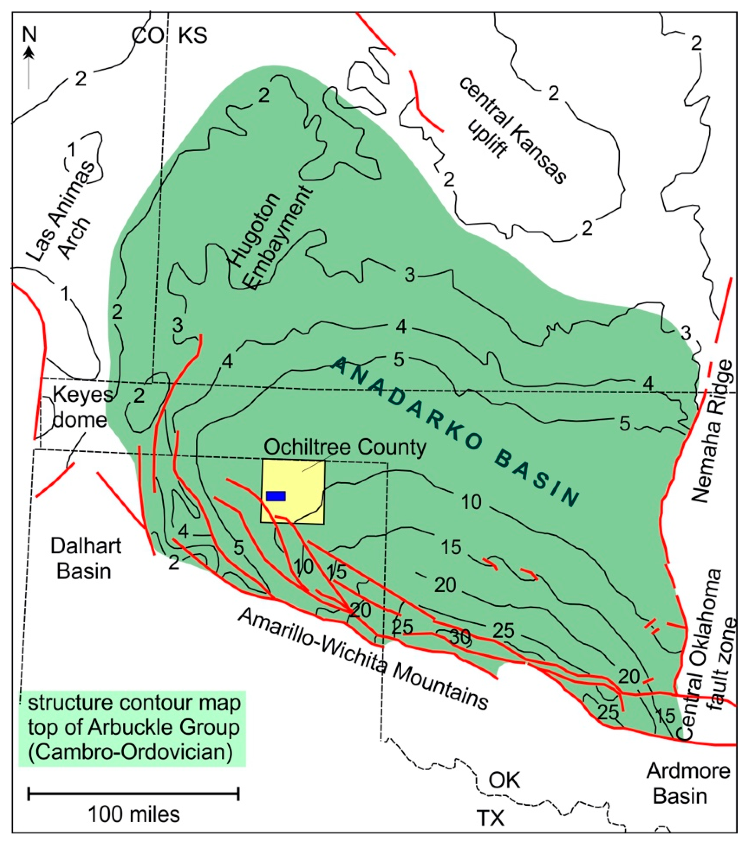
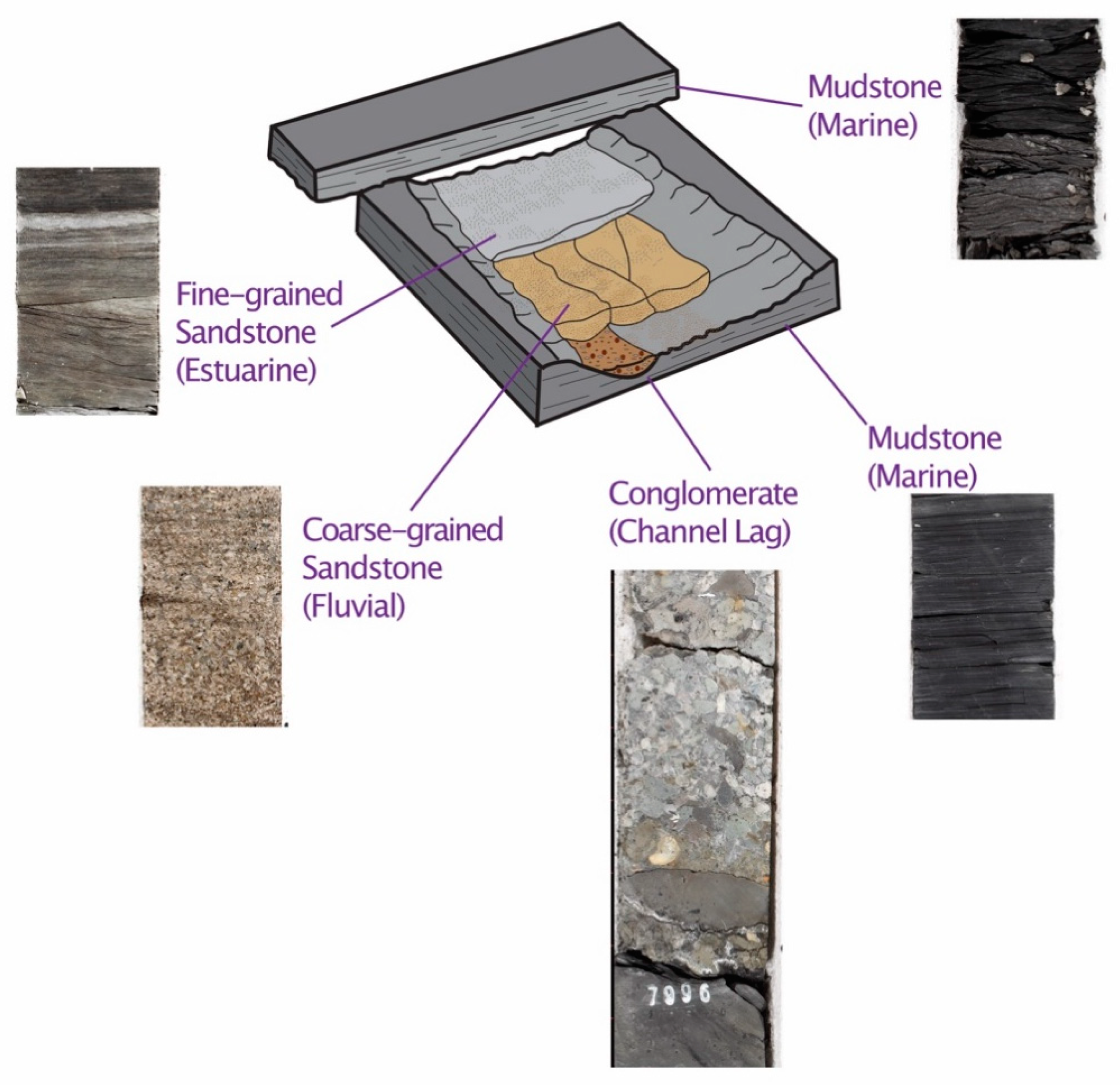