1. Introduction
The zero-emission cargo container vessel type, which is the subject of the study, is intended to navigate the waters of the Baltic and North Seas. All vessels designed for sailing on these waters are required to reduce CO
2 emissions by half by 2050, except the Norwegian fjords zone where by 2026 it needs to be reduced to zero. Additionally, emissions of environmentally harmful gases such as SO
X and NO
X are to be reduced too [
1,
2]. Because of this, all new vessels operating in sea and ocean areas will have to meet the Energy Efficiency Design Index (EEDI) standards for energy efficiency [
3,
4]. The most effective way to reduce pollutant emissions is to reduce the energy demand of the vessel. According to Equation (1) presented below, the power demand of the vessel propulsion unit
. corresponds to wet surface hydrodynamic resistance
, the frictional total-resistance coefficient
, and vessel speed
. magnified to the third power [
5].
New technologies, such as Air Lubrication System, Air Cavity [
6], and Contra-Rotating Propellers technology, enable reductions of
and
, but these two parameters do not have impact as high as the speed. That is why it is crucial to choose an appropriate speed profile for each mission. Interestingly, the most futuristic solutions considered when designing large vessels are: the use of classic sail technology, Wing Sail, Kite Sail kites, or Rotor Sail Feltner [
7,
8].
There are three main ways to achieve the reduction of pollutants emission of the vessel required by the standards. Additionally, changing the fuel type to low sulfuric and equipping the vessel with selective catalytic reduction system or optimising classic propulsion systems [
9,
10] should be taken into account. To meet all of the requirements listed, it is proposed to switch from high-emission power units to new-generation engines that burn fuels such as heavy fuel oil to liquefied natural gas or hybridisation of these drives, e.g., diesel with additional, heat recovery systems and energy storage system (ESS) on all new vessels as well as vessels currently undergoing modernisation [
3,
11,
12]. The most commonly used ESS for onboard utility are battery energy storage systems (BESS) and hybrid energy storage systems (HESS) based on fuel cells (FC) [
12,
13,
14]. Modern BESS for onboard utility can be classicized into two groups of batteries: lead-acid and Lithium-Ion (Li-Ion). Lead-acid batteries have been used as BESS on vessels for a very long time due to the high production costs of their Li-Ion successors. However, Li-Ion batteries have begun to be more often chosen by the designers due to higher gravimetric energy density and longer life cycle [
13,
14,
15]. Large vessels, in particular, require a special approach by designers. All energy sources have different specific values of volume and gravimetric energy density, which are crucial aspects when designing all types of electric vehicles.
Figure 1 presents a comparison of different viable energy sources. (Values shown for Li-Ion batteries may differ for specific manufacturing technologies of electrodes [
13].)
The electric grids of the vessel included multisource of power may affect the frequency and voltage stability of the AC grid. To reduce the noises generated by the renewable source and ESS, the main vessel grid is based on DC grid topology with mode-adaptive droop control [
19,
20,
21]. The DC grid topology allows for flexibility in connecting the grid with various electricity sources and any configuration thereof. This solution may also reduce black-out risk [
20,
21].
The more serious dangers to which the network may be exposed to is the impact of power fluctuations as a result of the wave at the encounter wave frequency, from the in-and-out-of-water effect, and the impact of fluctuations at the propeller-blade frequency. In order to minimize the impact of power peaks on BESS, an intermediate circuit equipped with super or ultracapacitors could be used. [
22,
23]. However, increasing the number of elements and intermediate systems of the vessel grid may negatively affect the system reliability and require future study [
24]. Moreover, the presented type of vessel is relatively large, and the potential fluoridation in real conditions can be minimized due to the high inertia of the ship and oversizing of the propulsion system by 15%.
Another aspect that should be looked into to achieve an optimal selection, dimensioning, and management of energy storage systems is the perspective of economic generation and utilisation of electricity for onboard power systems. One of the proposed methods was presented in [
25]. The proposed method is based on the particle swarm optimisation algorithm, which is divided into two components. The first solves the problem of finding the best size for the ESS. The second, estimates the best energy management during the cruise, taking into account the costs of fuel oil consumption, BESS installation and its inverter, and replacement costs for BESS, considering the size and the impact of ageing on storage. An additional difficulty for the new systems is the obligation for each vessel to obtain a special certificate issued by one of the certification associations like, for example, the DNV-GL or the Lloyd [
26,
27]. Such certificate confirms that the operation of the vessel equipped with the systems will be safe [
28]. This situation also sparks interest in new concepts such as HESS. While still requiring more studies about compatibility with power (PMS) and energy management systems (EMS) this could potentially lead to the application on all-electric vessels.
For this study, the cargo vessel concept with hybrid power source utilising diesel generators, vertical axis wind turbine (VAWT) and BESS with gross energy capacity up to 104,370 kWh were selected. The project assumes that the vessel will be equipped with one row of up to nine container stacks—each stack consisting of up to nine battery containers.
2. Materials and Methods
The authors of this article were presented with the challenge of designing PMS and EMSs for zero-emission cargo vessel as well as connectors for battery containers serving as energy storage. This leads to the concept of utilising PMS for control of battery management system (BMS) to decrease the number of necessary connectors, thus greatly reducing the risk of a malfunction while operating at high sea. This innovative approach for this kind of application is presented in this article.
2.1. Vessel Power System Topology
The vessel concept described in this work has been developed by Nelton Sp. z o.o. (Engineering Company dedicated to shipbuilding and offshore designing since 1999)
https://www.nelton.pl/ (accessed on 7 November 2020)) in a project which was funded by the European Union. The aim of the project was to provide technical solutions that are suitable for the prototype vessel. The vessels dimensions were: length of 165.25 m, 26.60 m of width, and 9.4 m of height with the cargo-carrying capacity of twenty-foot equivalent unit (TEU) equal 1504. The vessel is designed to operate at a speed of 13.5 kn. Based on the requirements of the project, an innovative solution for the electricity supply system of vessel was selected. Three independent sources would provide the energy necessary for the operation of the vessel. These sources are classic diesel generators, battery banks (including innovative interchangeable battery container storage), and vertical wind turbines. Interestingly the last two energy sources have never been previously encountered on such a large-scale vessel. An analysis of available solutions for energy, power and energy storage systems for container groupage vessel was also carried out. It was decided that the designed unit will be equipped with a hybrid power system based on six diesel generators (GenSet MAN 9L23/30H Mk3 with nominal power
, two vertical axis wind turbines (VAWT) with estimated nominal power
each, and two internal vessel battery banks with a total energy capacity
and nominal voltage
) with the possibility of flexible modification of the BESS with additional container battery banks (each with an energy capacity
and nominal voltage
), up to 63 containers. Only the built-in vessel battery banks need to be charged while in a harbour. Container battery banks can be replaced with charged ones. Discharged container battery banks are recharged while waiting in the harbour for the return of the vessel. This proposed solution with container battery banks provides more flexibility. It reduces the electric power demand during charge time in a harbour if all battery banks are charged simultaneously [
29]. The battery containers will be equipped with batteries and other systems, allowing them to be connected. For this purpose, it is planned to use 12 modules model EXX50V1-AR supplied by CORVUS. ORCA EES (Corvus Energy became pioneers on maritime Energy Storage Systems (ESSs) is the CORVUS system containing the previously replaced battery modules together with a dedicated BMS for modules [
30]. It is worth emphasising that at the moment, such a solution is not yet available on the maritime market.
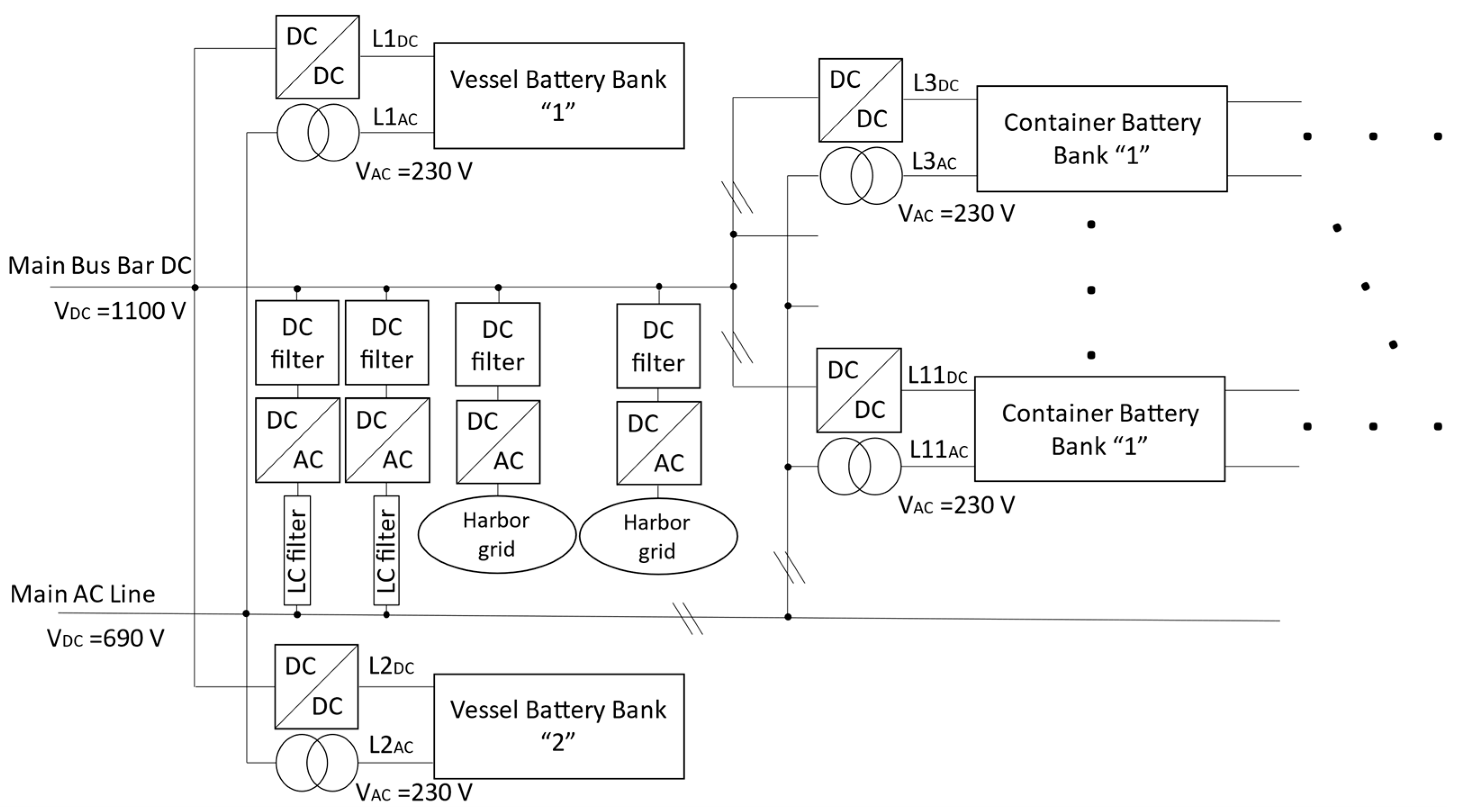
For the proper functioning of container battery banks, it is necessary to power onboard equipment with an alternating current of 230 V and 60 Hz. This presents an opportunity, using the inverter as an AC power source will also enable EMS to be used to control it based on energy demand information provided by BMS. The proposed system architecture, presented in
Figure 2, allows the EMS system to control the energy consumed and provides the appropriate value of the power from the battery banks, using DC / DC converters. It also considers the BMS demand for electricity in the form of 230 V/60 Hz AC, which is supplied from the AC grid.
The first number after the name “Container battery bank” indicates the order number of the battery stack. The second number indicates the order number of the bank in the container stack. Additionally,
Figure 2 indicates DC lines for each of the vessel battery banks and container stacks of battery banks.
Figure 2 contains the AC lines for the needs of the vessel battery bank and container battery banks. As can be seen, the system is symmetrical and redundant with the possibility of switching between power lines.
The last element subject to the EMS system are the harbour power connectors responsible for providing electricity to the unit when the vessel is docked. During this time, energy storage in the vessel battery bank, as well as container battery stores, are charging. These connectors are in the form of AC/DC and AC/AC converters. AC/DC converter connects the AC grid in the harbour with the main DC line on the vessel. The AC/AC converter (transformer) connects the AC grid in the harbour with the AC line. This makes it possible to use both chargers if the harbour infrastructure does not provide connectors with a significant electric power value [
31].
ORCA EES system is an integrated system to enable easy and efficient integration and control of BMS systems with PMS and EMS systems. The EMS system chosen by the user will be able to control all battery modules by communicating with BMS on the same DC rail of the container battery bank. The three main categories of control information available for the EMS communication interface are system data, system commands, and alarms.
2.2. Control Hierarchy and Topology of the System
Control will be implemented in a hierarchical structure based on event dynamics. Management will be governed by EMS (level 3 based on the energy demand predictive model based on the previous average electricity demand. Level 2 will be responsible for power and energy control for the predicted near-future demand using more accurate models and more accurate short-term forecasts implemented by EMS, taking into account data received from BMS. Level 1 will implement control in a short time window (ranging from an hour to 15 minutes depending on the decision of the project implementer) realised by PMS to ensure constant power reserve. Power control carried out by PMS will be based on voltage control to allow the flow of currents of appropriate intensities. The lowest control level (level 0) is the direct control of devices ensuring unit operation and carrying out operator/crew instructions. The hierarchical proposal structure was presented in
Figure 3 [
32].
The hierarchy of control systems presented in
Figure 3 allows the EMS system to fully control the distribution and power demand in the vessel grid. The main objectives of the control system are: to maintain DC grid voltage, to maintain state of charge (SoC) and State of Health (SoH) of batteries within safe service limits, to ensure optimal operation of batteries and generators, to ensure adequate transient dynamics during load changes and to guarantee system stability. The control structure can be divided into high and low-level controllers. High-level control includes the PMS management system, which is responsible for load sharing and system protection. In addition, high-level control may include an EMS, which has been designed to optimize further energy efficiency as well as system reliability and battery life. The low level controls the converter controllers and includes power, current, and voltage controllers. It can also contain internal and external loops. The inner loop is usually a current regulator, while the outer loop regulates the voltage or power and generates a reference current to control the inner loop of the transducers. The internal loop or current regulator then follows the reference current to provide the required power supply while maintaining grid parameters at the appropriate level. The basic way to accomplish this task is to control the converters using a signal generated by voltage regulators and currents subject to a PMS. It is worth noting, however, that due to the homogeneous nature of the grid, it must also contain speed regulators. The last key element for the correct operation of the system is BMS for vessel and container batteries. They must be placed below the EMS system in the control hierarchy because they are equipped with a mechanism allowing analysis of the state of charge and other battery parameters necessary for control [
33,
34]. The concept of the topology of EMS and PMS for the onboard grid is shown in
Figure 4.
The essential function of EMS management is to guarantee that the demand for electricity necessary for all systems is efficiently met and, in the event of an emergency ensures the safety of the crew and the unit. Demands for power and energy are calculated on an ongoing basis based on the activities of the crew in accordance with guidelines. These guidelines are calculated in advance based on the parameters of the course realised by the vessel.
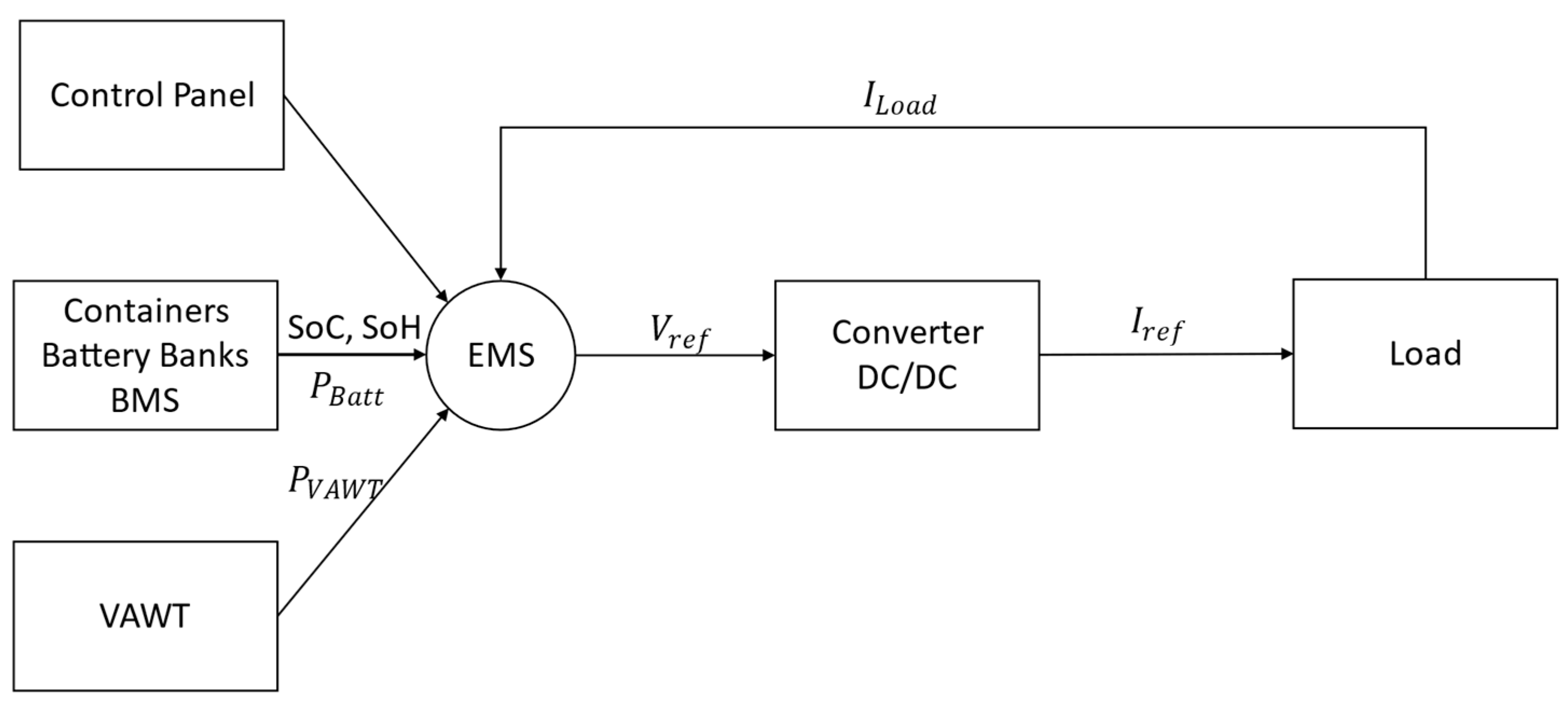
The algorithm realised by EMS must include demand control inverters for receiving electricity (current and voltage control loop) and take into account the signals sent by the BMS (SoC, SoH) as well as account for emergency situations related to work at sea. An example of such a situation is, e.g., disconnection from one of the containers, during a storm, resulting in the loss of connection with one of the BMS. The concept of EMS management for energy storage is shown in
Figure 5. The example shown in the figure concerns the control of the DC/DC converter by the EMS system. Equivalent solutions will be applied for AC/DC and DC/AC converters. Thanks to this approach, the EMS will be able to freely transfer electrical energy between AC and DC grids of the vessel.
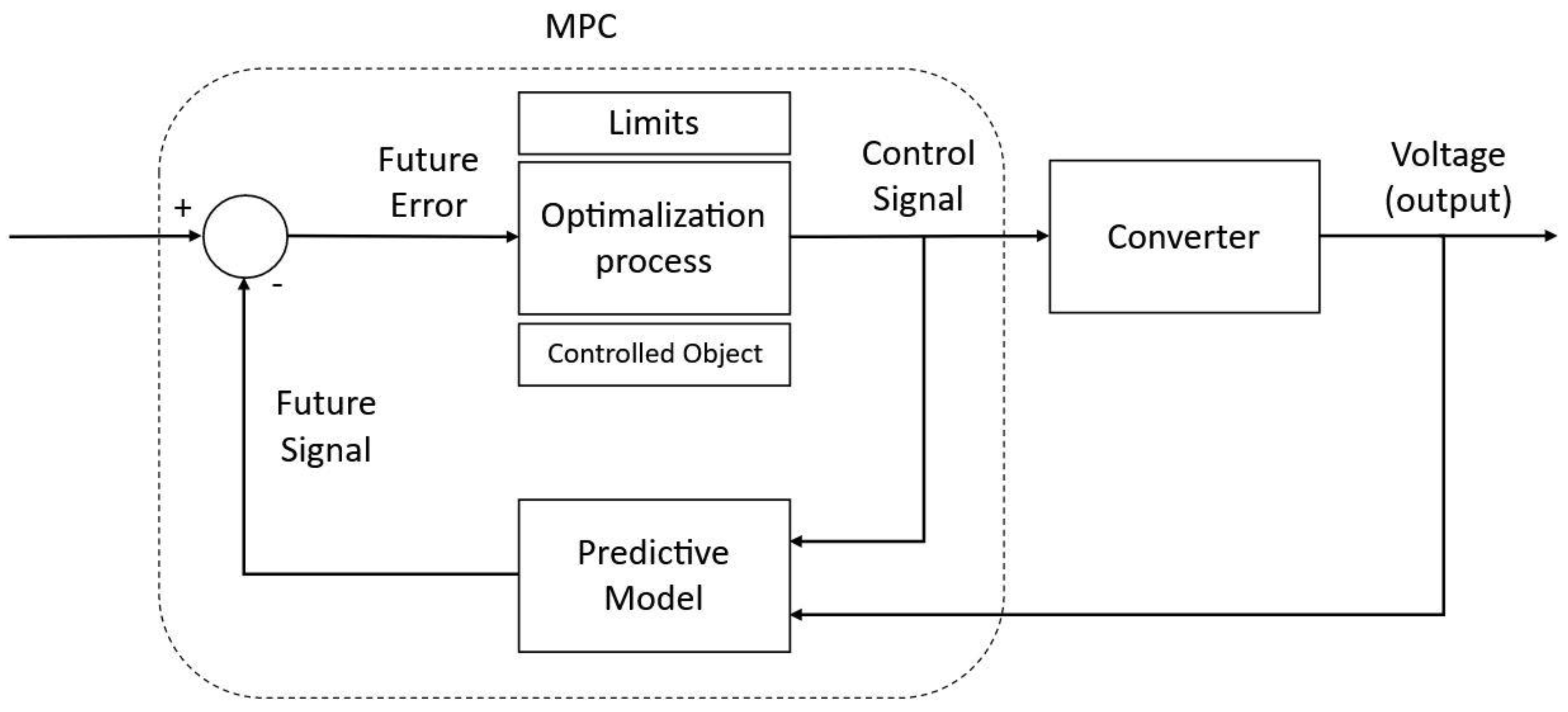
In order to optimize energy consumption, model-based predictive control (MPC) will be used. In this solution, the control will use measured data (battery status controlled by the BMS, knowledge about the possibilities of generators, instantaneous demand of devices, and planned route), prediction of future demand for electricity, and the disturbances resulting from atmospheric conditions [
5]. The inverter control structure that implements MPC control is shown in
Figure 6. Its goal is to adjust the output voltage. The future error signal between the reference and estimated and filtered future output voltage of the observer or predictive model is fed to the optimizer as an input signal. The goal of MPC is to generate the optimal control signal for the inverter.
2.3. Minimum Requirements for Control System
Figure 6 presents the schematic of converter control loops and devices controlling them. This system has to be designed according to Det Norske Veritas and Germanischer Lloyd (DNV GL) rules for this kind of vessel. First of all, in order to fulfil the basic design principle, all instruments belonging to separate essential processes need to be independent. This will be fulfilled as an electrical grid and battery will be governed by an energy management system autonomous from the rest of the vessel systems. In case of failure of one of the systems under its management, the EMS will act accordingly to ensure other functions are maintained. The system will function primarily under automatic control based on previously realised courses and current mission. According to norms the Computer-based systems response time should be less than 0.1 s for data sampling, 1 s for other indications, 2 s for alarm presentations and update of screen views, and 5 s for fully updated screen views including the start of a new application. If such a need occurs, it will be possible to control it manually via a console installed on the ship’s bridge. This console will have to be protected by password to avoid manipulation by unauthorized personnel. According to the general requirements, this system will have two autonomous power supplies. One from the electric grid it governs and the second one for the initial launch or emergency situations [
35,
36].
One of the communication protocols supported by the ORCA EES system is the Ethernet protocol. It enables battery pack control (Ethernet TCP/IP). The application of this solution requires a special Internet of Things IoT device, which CORVUS provides. The central computer of the operator’s station, in which the EMS system and the PMS system will be installed, will send control signals through dual Local Area Network computer networks to local Programmable Logic Controller which will control for example grid converters. In addition, to implement the BMS connection using this protocol, it is necessary to consider the IoT devices provided by the ORCA system manufacturer.
3. Proposed System Implementation
3.1. System Application
In any given container stack, the container battery banks are connected in parallel with each other, while the entire stack is connected in series with the DC/DC converter. This situation is analogical when connected to the AC line, where the containers are connected in parallel with each other and in series with a transformer providing 230 V/60 Hz voltage on the container side. This voltage is required to meet the needs of our own BMS system equipment onboard the container. The connection diagram is presented in
Figure 7. The first digit after the name “Container battery bank” indicates the order number of the banks in the container stack.
The maximum number of connected containers is determined by many parameters resulting from the system design. For example, one such parameter is the maximum power for which the DC/DC converter connected to the stack will be designed. This is because each of the stacks is, from the point of view of the whole system, an autonomous energy store that can be connected or disconnected at any time. The project envisages equipping the unit with one row consisting of up to 9 stacks. Each of the stacks consists of up to 7 container battery banks. The battery capacity depends on the range of battery operation to the depth of discharge (DoD) set by the authors of the study, up to 80% [
37]. This results in a theoretical capacity of 10,437 kWh and a usable capacity of 8350 kWh per stack. For routes where electricity demand will be smaller, the system assumes the possibility of reducing the number of stacks in a row or containers per column.
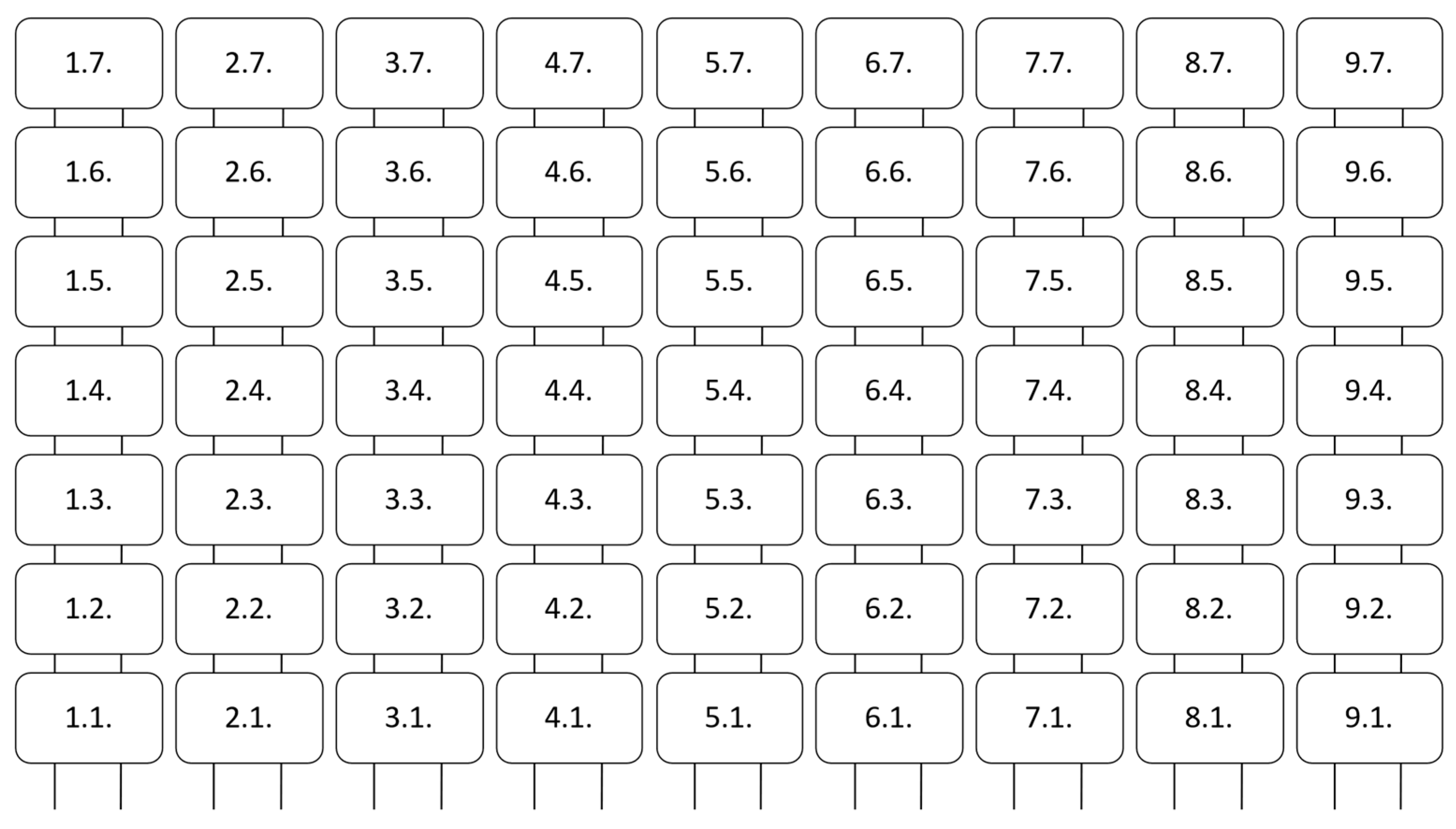
Figure 8 shows the placement and numbers assigned to containers. In
Figure 8, in the block representing BMS, the first digit is the stack number, and the second number is the serial number in the stack of the container battery bank.
It is important to mention the three most crucial parameters of energy reservoirs that should be considered when designing the EMS system and planning the use of these reservoirs. These are SoC, i.e., the state of charge affecting the battery voltage, SoH, the state of health affecting the possibility of achieving the highest possible SoC and DoD, and the depth of discharge that affects battery health. During operation, it will be necessary to decide on the allowable DoD, which affects the number of possible charge-discharge cycles, and therefore the lifetime of the BEES. The EMS system will instead use SoC to monitor whether acceptable DoD has been achieved. However, SoH is an important parameter mainly from the point of view of BMS, which in case of detecting its low level will notify the EMS that the container should no longer be used and it is necessary to replace the given battery module or the entire container. Moreover, to evaluate BESS and extend SoH of battery EMS have to consider the thermal conditions [
38,
39].
The system using primarily the DC grid used on the vessel is better than the most currently popular architecture of 60 Hz AC grid in terms of higher power quality, greater reliability, high power transmission efficiency, and lower energy losses [
19]. Additionally, the chosen solution allows for the possibility of eliminating phase synchronisation and large low-frequency transformers, which is beneficial for power systems equipped with many sources of electricity with different nature of work. The DC system of the vessel, the topology of which is presented in
Figure 2, will be used mainly on high power converters.
In order to obtain DC voltage, an output voltage rectifier (AC/DC converter) of generators set (GS) and wind turbines with a vertical rotation axis (VAWT) is used. The main propulsion (M) and bow thruster (BT) are connected by independent inverters (DC/AC converters). For safety reasons, it is anticipated that M and BT will be equipped with at least two AC/DC (Chopper) converters, which enable uninterrupted operation in emergency situations. Vessel battery bank and container battery banks are connected directly to the main Main Bus Bar DC via DC/DC converters, in the case of container banks, a dedicated converter for each stack is used. This solution increases the number of available independent energy sources in the DC grid. In addition, the DC grid of the vessel will be connected to the AC grid by two converters used depending on the energy flow. The energy stream will be diverted from the DC grid to the AC grid: DC/AC converters are presented in more detail in
Figure 9. During standstill in the harbour, it is possible to supply the vessel with electricity available in the harbour grid through harbour power connections (called shore power connection). Two harbour connections will be directly connected to the DC grid through a rectifier. This solution will allow faster charging of battery banks for low power connections available in the harbour.
The main source of electricity in the DC installation depends on the operating mode implemented. In zero-emission mode, they are container battery banks housing the ORCA EES system supported by 2 VAWT. In Diesel-Electric mode, they are diesel generators. Hybrid mode, as the name suggests, allows using all these energy sources in parallel. Another important element of the DC installation are the power electronic converters that will enable the energy management system (EMS) to control the energy flow in the system depending on the vessel’s needs and operating mode. An excellent candidate to accomplish this task is DC/DC Buck-Boost converters that use thyristors. This solution will enable a simple, and thus less vulnerable system architecture. The use of thyristors instead of transistors enables the flow of high currents and high voltage [
40]. The inverters will be located in the switchboard room at the battery deck level. It is possible that a separate room within the engine control room will be chosen, depending on the space available.
At the project implementation stage, it will be possible to change the voltage and frequency of the grid by dimensioning the inverter accordingly.
3.2. Energy Balance and a Usual Operational Range of Vessel
The energy balance the following operation modes have been highlighted: regular operation, manoeuvring, harbour operations, and emergency operations. Each of the operation modes is characterized by different required power for each of the loads and load groups that are found on board the vessel.
Regular operation—default work mode for the vessel, when the cruising speed is equal to service speed and powering all the equipment necessary for normal functioning. For this analysis, it was assumed that service speed is equal to 85% of the maximum continuous rating. In reality, it is possible that this speed will be lower in order to optimize fuel consumption and cost reduction.
Manoeuvring—group of operations, which the vessel realises in the area of harbor waters or during a cruise through a channel with a limited speed equal to 8 knots.
Harbor operation—mode of operation when the vessel is moored in a harbor or waiting on a roadstead.
Emergency operation—mode in which the vessel is operating during emergencies such as black-out, onboard fire, or generator failure. In this mode, most loads are turned off, except for the ones necessary for the safety of the crew and returning the electro-energetic system to regular operation after the emergency is over.
The group of loads consists of 6 groups of devices connected to the grid via converters. The most significant load during regular operations and manoeuvring is the main drive where the average power consumed is 6800.00 kW for regular operations and 3200.00 kW for manoeuvring. During harbor operations, the main load is the converter servicing the load group “Vessel battery bank” which requires a maximum of 365.40 kW. During emergency operations, the most significant load is a group of loads marked as “other” in the analysis with a power requirement of 253.60 kW. These are devices necessary for maintaining the operation of systems providing safety for the crew. All the load groups are presented in
Table 1.
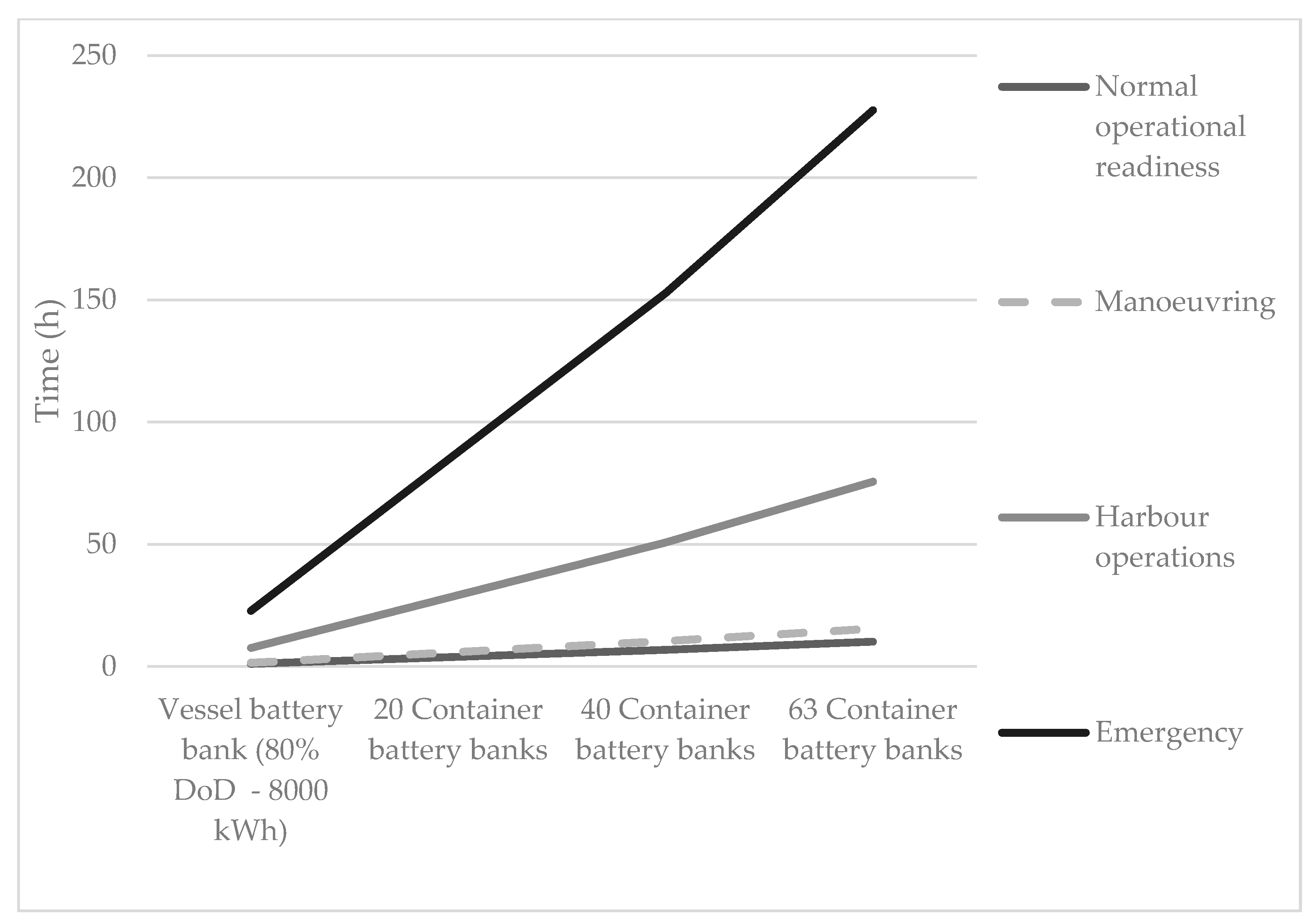
The aforementioned analysis was used to create two functions for a specific number of container battery banks: operation time shown in
Figure 10 and the operation range of the vessel shown in
Figure 11. These two functions are essential for optimising the operation plan by the shipping company utilising the described vessel. Depending on the chosen cruise routes, an appropriate number of battery bank containers can be prepared in each harbour visited during the cruise and the time necessary to load ones already on board. In tandem with other tools such as weather forecasts and data gathered during already realised voyages, this can lead to the creation of a highly optimized operation plan resulting in reduced emission of gases, fuel consumption, and operation costs.
It is worth noting that while the vessel described was designed for operation on the Baltic Sea, these results can be used for the creation of similar vessels and operation plans for other reservoirs such as the Mediterranean, Black Sea, or the Gulf of Mexico.
3.3. Baterry Charging
While it can be assumed that additional battery banks will be discharged as the first ones, for safety reasons the highest possible operational capacity of onboard battery banks should be maintained by the EMS. For this purpose, one of the important aspects that needed to be analysed in this work was the way of recharging the onboard batteries of the vessel during cruise and docking.
Table 2 shows the available charging power of battery banks depending on the number of available generators and the kind of operations performed by the vessel.
Table 3 shows the time required to charge the onboard battery banks.
3.4. Cruise Analysis
To analyze the demand for power of the ship, an actual route of a unit similar in dimensions to the vessel proposed in this paper was studied. An analysis of the cruise of Bernhard Schepers AG vessel was used.
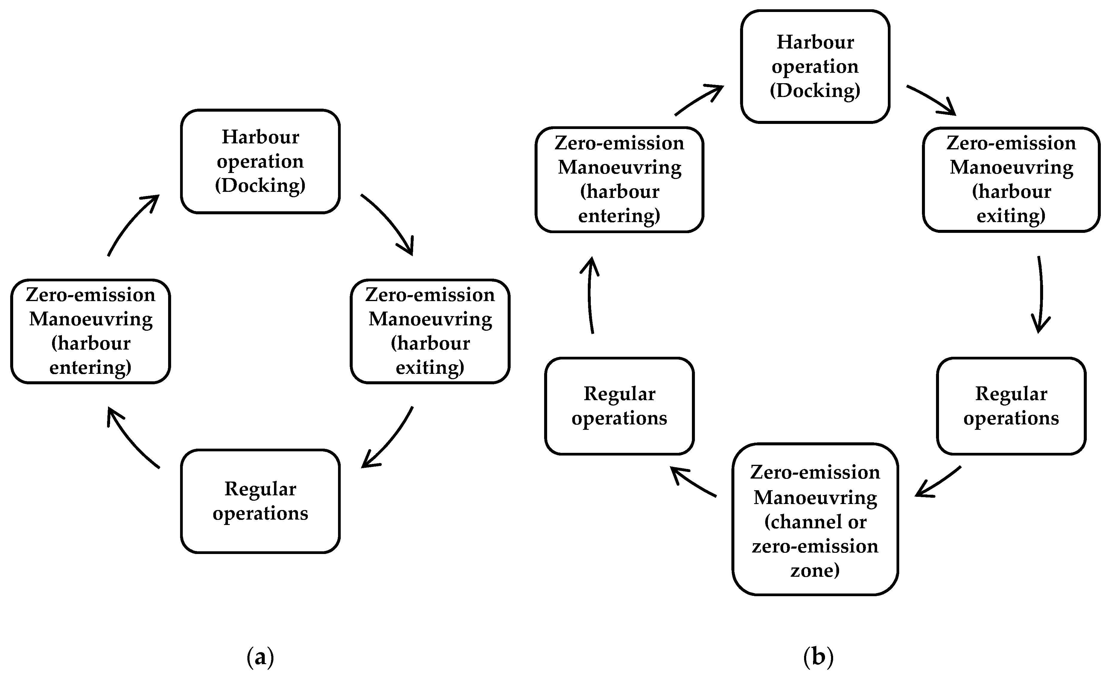
Figure 12 represents operation sequences realised by the vessel during two standardized variants. All of the mentioned operations have been described in
Section 3.2. Variant 1 represents a simple sequence of operations which the vessel has to perform during a cruise from one port terminal to a port terminal in another harbour. Analogically, Variant 2 presents a similar cruise between port terminals of different harbours and an additional requirement for a zero-emission cruise. An example of such a cruise would be passing a mid-land canal or other zero-emission zones. The ship carried out missions as in the diagram shown in
Figure 12.
The power demand and SoC evolution shown in
Figure 13 were prepared from the BEES point of view. Average values of power demand were assumed for the calculations. The calculations do not take into account the transient states that may occur under real conditions.
Figure 13 shows power required from BEES perspective and change of energy magazines SoC during the time of the cruise for mission variants presented in
Figure 13 with all the data presented in
Table 1,
Table 2 and
Table 3 taken into account. Both variants have been developed based on real missions that have been realised by Bernhard Schepers AG vessel, size and functioning of which is similar to the theoretical vessel presented in this work.
Figure 13a presents the sequence of operations for variant 1. For the purposes of this simulation, an average power requirement on route Copenhagen–Aarhus was used. The vessel was equipped with the onboard battery bank only. During the cruise, the vessel required an hour to leave the harbour in Copenhagen in zero-emission mode. Next, the vessel cruised for 6.5 hours with 5 generators running, which enabled the battery bank to be partially recharged. Finally, the vessel required another hour in zero-emission work in order to enter the harbour in Aarhus.
Figure 13b presents the sequence of operations for the second variant, and this time an average power required for the course on route Hamburg–Frederica was used. For the simulation purposes, it was assumed that the vessel is equipped with an onboard battery bank as well as additional 36 container battery banks. During the course, the vessel required an hour in zero-emission mode to leave Hamburg harbour followed by 10 hours to pass Kilon canal. Next, for 9 hours, it continued to cruise on the Baltic Sea with 5 generators running until it arrived in Frederica where an hour in zero-emission mode was required to enter the harbour.
4. Conclusions
Based on available literature and catalogues of products and technologies available on the market, solutions enabling the design of PMS and BMS system for a cargo vessel equipped with innovative triple energy source system with a possibility of work in zero-emission mode and optional function of autonomous operation have been discussed.
Authors of the article have shown that using available technology of storing electrical energy (example of which is container battery banks offered by Corvus) and taking into account developed energy connector for container battery banks it is possible to design EES along with EMS, PMS and BMS for an all-electric cargo vessel. By implementing solutions proposed by authors, it is possible to reduce the number of crew members necessary for the operation of such a vessel in comparison to older vessels of the same class.
From the operation ranges estimated in the energetic balance of the vessel one learns that based on the proposed ESS, the vessel can realise cruises of up to 136 nautical miles while operating solely in the zero-emission mode. Moreover, this cargo vessel can operate in the hybrid mode utilising diesel generators fulfilling the emission norms presented in the introduction. Naturally, in this mode, an even greater operation range can be achieved. A big part of the necessary onboard devices could not be selected or dimensioned on the current stage of the project due to the scarcity of available information on the power system of the vessel as a whole. Additionally, specific subsystems are not widely available on the market and will need to be designed and assembled for the project.
According to the authors, future research should focus on monitoring orders to minimize the need for energy and increase the range of operation in the zero-emission mode for similar class vessels. Additionally, in future studies, it would be interesting to further investigate the carbon footprint of the vessel equipped with the proposed system. It is worth noting, however, that in such a study, carbon footprint, associated with energy production in each of the countries visited by the said vessel would also need to be taken into account. Additionally, in future studies, the carbon footprint associated with electric energy generation for the countries where onboard batteries would potentially be charged must be taken into account.


 ,
, 


