Article

The Impact of Process Heat on the Decarbonisation Potential of Offshore Installations by Hybrid Energy Systems

Department of Energy and Process Engineering, NTNU Norwegian University of Science and Technology, 7491 Trondheim, Norway
*
Authors to whom correspondence should be addressed.
Energies 2021, 14(23), 8123; https://doi.org/10.3390/en14238123
Submission received: 20 October 2021 / Revised: 20 November 2021 / Accepted: 30 November 2021 / Published: 3 December 2021

Abstract

:
An opportunity to decarbonise the offshore oil and gas sector lies in the integration of renewable energy sources with energy storage in a hybrid energy system (HES). Such concept enables maximising the exploitation of carbon-free renewable power, while minimising the emissions associated with conventional power generation systems such as gas turbines. Offshore plants, in addition to electrical and mechanical power, also require process heat for their operation. Solutions that provide low-emission heat in parallel to power are necessary to reach a very high degree of decarbonisation. This paper investigates different options to supply process heat in offshore HES, while the electric power is mostly covered by a wind turbine. All HES configurations include energy storage in the form of hydrogen tied to proton exchange membrane (PEM) electrolysers and fuel cells stacks. As a basis for comparison, a standard configuration relying solely on a gas turbine and a waste heat recovery unit is considered. A HES combined with a waste heat recovery unit to supply heat proved efficient when low renewable power capacity is integrated but unable to deliver a total CO2 emission reduction higher than around 40%. Alternative configurations, such as the utilization of gas-fired or electric heaters, become more competitive at large installed renewable capacity, approaching CO2 emission reductions of up to 80%.

1. Introduction

Global warming is an ongoing process observed worldwide, forcing all countries to undertake necessary steps to prevent and mitigate climate change. According to the Intergovernmental Panel on Climate Change (IPPC), the current estimated anthropogenic global warming rate is 0.2 °C per decade due to past and ongoing global greenhouse gas (GHG) emissions and is likely to reach 1.5 °C between 2030 and 2052. Global warming above the mentioned 1.5 °C will increase the risk of long-lasting or irreversible changes to natural systems [1]. To avoid this unfavourable scenario, far-reaching changes and rapid energy transitions are needed in all sectors. Among those, the offshore sector is supposed to reduce its carbon footprint. Although the offshore sector is directly responsible for a relatively small share of the GHG emissions, its contribution is relatively large in certain countries. For instance, in Norway, the oil & gas sector is responsible for 27% of the Norwegian GHG emissions in 2020, principally related to offshore operations [2]. Accordingly, ambitious sectoral targets must be set to curb national emissions according to the pledged levels (Norway has committed to at least 50% and towards 55% reduction in GHG emission compared to 1990 levels [3]). The Norwegian oil and gas industry has announced the goal of a 40% reduction in its absolute GHG emissions by 2030 compared with 2005, and then secure a further decline to near zero in 2050 [4].
Several options exist for reducing CO2 emissions in the offshore sector [5]. A first set of options consists of mature technologies and approaches that have been already applied in some cases, or else thoroughly analysed, such as the introduction of combined cycles, and the optimization of control strategy. As presented in [5], the implementation of an offshore combined cycle has the potential to reduce cumulative CO2 emissions by 32.2%. Going into more detail, Pierobon et al. [6] investigated three cycles: organic and steam Rankine cycles and air bottoming cycle for offshore platforms. The study concluded that the organic Rankine cycle outperforms the equivalent steam Rankine cycle in terms of CO2 reduction, but also pointed out the relatively high cost of the expander and of the primary heat exchanger. Another approach to optimisation of the energy efficiency in oil and gas offshore platforms is discussed in [7], where the proposed methodology, in comparison with the standard case, shows up to 25–30% energy savings and CO2 emissions over the field’s lifespan. Although these methods proved their feasibility and could be relatively easily implemented, the potential for emission reductions is limited to ≈20–30% [7,8,9].
A second set of options has been thoroughly assessed in recent years and consists of the integration of renewable energy sources: wind [10,11], but also other sources such as wave and solar energy [12]. Korpås [10] analysed operation of four 5 MW wind turbines in parallel with two gas turbines for power supply in a real case study of an offshore oil platform. The results confirmed the expected CO2 and NOx reductions along with GT fuel savings, but also the concern of the gas turbine subjected to frequent on/off switching. Riboldi and Nord [11] developed a method for definition of the optimal design of an offshore combined cycle power plant integrated with a wind farm. The analyses showed that the optimized plant design with integrated wind farm can lead to a reduction in CO2 of about 24.4% compared to a simple GT cycle not integrating a wind farm. Renewable power does not involve emissions per se but, due to its irregular nature, it may require conventional fossil fuel-based systems as backup. This can cap the degree of decarbonisation achievable, where emission reductions have been reported between 25% and 50% [11,13].
The pursuit of net-zero emissions has finally led to a third set of options, including rather different approaches. Offshore electrification has been widely studied as it allows to potentially avoid any local emissions. However, some uncertainties remain on the economics of electrification projects and on the global impact on emissions [14]. Offshore carbon capture and storage (CCS) might also be a feasible technology [15] but it would allow only to approach net zero emissions, still posing a high economic penalty.
Another possibility is to couple renewable sources with energy storage in a hybrid energy system (HES). For instance, hydrogen storage along with electrolyser and fuel cell stacks can offset the irregular power contribution of offshore wind [16]. This concept maximises the exploitation of carbon-free renewable power while minimising the contribution of conventional power generation systems such as gas turbines (GTs). However, in a previous study, the maximum CO2 emission reductions obtained were only slightly higher than those obtained by a conventional integration of renewable wind power [17]. Apart from technological and design limitations, a reason for this was the need for process heat. Even if the power could be completely decarbonised, not finding a good solution for supplying process heat might result in additional emissions. This study aims to address this issue and assess how the demand for process heat affects the potential for decarbonisation of offshore plants. The knowledge generated will contribute to identify suitable pathways towards near zero offshore emissions. Although the focus of the analysis is on hybrid energy systems, it is the authors’ opinion that the main findings can be extended to schemes involving simple integration of renewable power (e.g., offshore wind) with conventional power units (e.g., gas turbines), providing useful insights for the integration of offshore renewable sources in the oil & gas sector. Few previous studies considered heat demand in their analyses of offshore energy supply options [18,19], in fact, the heat requirements are often disregarded. To the best of the authors’ knowledge, no previous study performed a systematic analysis of the most suitable option to supply heat in settings including renewable energy integration. Filling this knowledge gap is the main novelty introduced by this work.
The paper is structured as follows. After a brief overview of the typical power and heat requirements of an offshore platform, the HES at the basis of the analysis is described, followed by the methods investigated to supply process heat and by the definition of a generic offshore installation. Then the results of the simulations are reported and discussed. Lastly, a summary of the key findings is provided in the conclusions.

2. Power and Heat Demand in Oil & Gas Extraction

Offshore installations for the extraction and first treatment of oil & gas are complex plants that require power and heat to operate. Pumping is a main source of power consumption. Pumps are needed to elevate the pressure of production outputs (oil and produced water), as well as to circulate cooling water and to perform water injection. When gas is present, a significant power consumption is associated with gas compression (e.g., gas export, gas lift, gas re-injection). These two power-consuming processes constitute the main power requirements, while minor contributions are linked to other auxiliary functional units such as heating, ventilation, air conditioning and lights systems. Heat requirements exist both at high and low temperature. The crude oil separation process normally requires large amounts of thermal energy at relatively low temperatures [20]. The heat is supplied to the separation train where gas and water are separated from the crude oil. Heating the oil contributes to decreasing the viscosity of the oil phase to facilitate the process. Temperature levels in the range of 50 to 90 °C are commonly sought [18]. Low quality heat might also be used from other processes, for instance fuel gas heating. Higher quality heat is requested as well in offshore installations. Crude oil stabilization, a partial distillation process that makes crude oil safe for shipment in tankers or of a quality suitable for sales or pipeline transportation, requires heating of the live crude in a furnace or heat exchanger to around 180–200 °C [20]. Another process requiring heat at relatively high temperature levels is gas dehydration, which is implemented to prevent corrosion issues and hydrate formation in the gas pipelines. For instance, glycol dehydration units require reboilers operating at around 200 °C [21]. All in all, both power and heat are always demanded in an offshore installation, with the absolute amount of those energy requirements being case-specific.

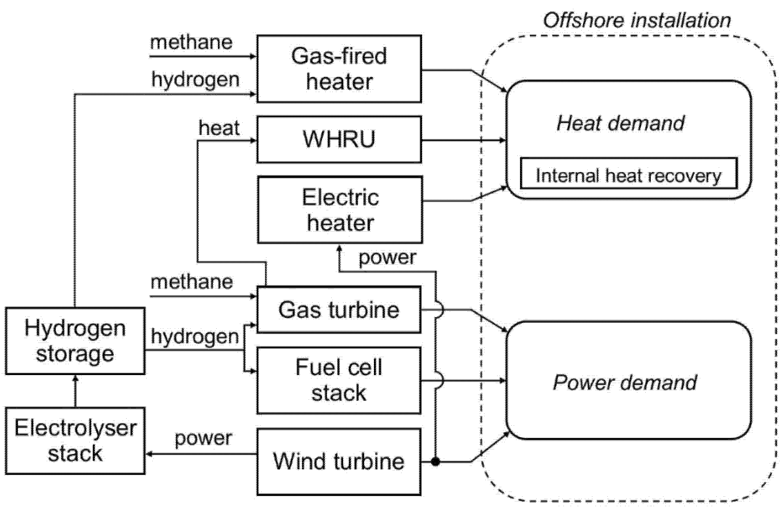
3. Hybrid Energy System for Offshore Installations

Hybrid energy systems (HES) integrate renewable energy sources with energy storage technologies to allow meeting the energy demands of a given system. Normally, a HES includes conventional fossil fuel-based power and heat generation as a backup option to deal with the irregularity of renewable power. Different HES configurations have been proposed and thoroughly assessed for several stand-alone systems [22], including offshore installations [16]. In particular, the authors of this paper designed and optimised a so-called Hybrid Energy System for stable power and heat supply in OFFshore oil and gas installations (HES-OFF) in a previous publication [17]. The HES-OFF concept integrates and combines wind power, a hydrogen storage system (including a fuel cell and electrolyser stacks) and a gas turbine (GT), the flue gas of which is used to provide heat to the offshore processes requiring it. The current study expands the scope by considering a range of alternative options for supplying heat, as detailed in Section 4. Otherwise, the same technologies, models and operational strategies are considered. The HES-OFF concept along with additional heat options are outlined graphically in Figure 1. In the following paragraphs, an overview of the modelling approaches is provided, while for more insights reference should be made to [17].
The GT simulated is a GE LM2500 + G4 (rated power 33.3 MW), modelled based on the performance curves provided by the manufacturer. In the analyses, the GT model allows co-feeding of hydrogen up to a maximum of 22% vol. This value is feasible after minor upgrades to the low NOx combustors [23]. The waste heat recovery unit (WHRU) is modelled in the Thermoflow software suite [24] as a counter-flow vertical finned tube heat exchanger, replicating an existing offshore unit. The fuel cell and electrolyser stacks are based on the proton exchange membrane (PEM) technology. They are modelled in MATLAB [25] with a steady-state, zero-dimensional approach, where polarization curves and performance characteristics have been validated against the technical data of modern commercial stacks. Such an approach allows considering the part-load efficiencies of the stacks. The wind turbine model was based on the power curve of the Siemens Gamesa SWT 6.0–154 WT, a commercial three-bladed floating turbine. To calculate the wind power available, a dataset of wind speed measurements was retrieved from an open-source database of scientific-quality weather and energy data [26]. The wind speed data refer to an offshore area in the North Sea in 2017 and have a resolution of 1 h (a higher resolution was used in previous work to perform dynamic analysis, however it was deemed unnecessary for the scope of this study). The integrated model, combining the various units of the HES, was developed in MATLAB [25].
In order to simulate the HES, an operational strategy is needed. Such a strategy must ensure that platform’s power and heat demands are met at any time. Another constraint implemented is to ensure that the hydrogen balance is closed at the end of the timeframe considered (a year in this case). Additional system constraints are accounted for, normally related to the process equipment (size of fuel cell and electrolyser stacks, maximum hydrogen to the GT, maximum size of hydrogen storage, etc.). The objective of the operational strategy is to minimise CO2 emissions. The main principles implemented are as follows:
  • Wind is the primary source of power. The fuel cell stack is the first backup power source, while the GT covers the remaining gaps in power production.
  • Surplus wind power is converted to hydrogen rather than dissipated unless system constraints make it unfeasible (e.g., to constrain the size of hydrogen storage).
  • Hydrogen produced is primarily used in the fuel cell. Whenever the maximum capacity of the fuel cell stack is reached, the hydrogen surplus is fed to the GT.

4. Methods to Supply Process Heat

Several alternatives exist to generate process heat to meet offshore requirements. The most standard options applied today in the offshore industry consist of the utilization of waste heat from gas turbines (GT). This option was tested (Section 4.2) and compared to alternative methods. The use of gas-fired heaters, another quite common option, was assessed, with the possibility to use mixtures of natural gas and hydrogen as fuel (Section 4.4). Other less conventional methods are also considered, namely the utilization of waste heat available in the offshore plant (Section 4.1) and the utilization of electricity via electric heaters (Section 4.3). In the following sections, the various options included in the analysis are briefly discussed.

4.1. Internal Heat Recovery

An offshore installation is a complex plant that includes several processes that either consume or produce thermal energy. Available analyses [27] point to the theoretical possibility to cover the entire heat demand by exploiting the waste heat available from offshore processes, although challenges exist for practical implementation [20]. This internal heat recovery configuration relies on the non-trivial task of designing a heat management system that is able to match the heat demand—both in quantitative and qualitative terms—with the waste heat availabilities. Such systems are feasible in theory, but their feasibility is case-specific and needs to be assessed once a case study is selected. In this paper, it will be assumed that the internal heat recovery configuration can always be implemented. The rationale is to provide a “best-case scenario” where the heat demand, being provided internally, can be decoupled by the strategies to supply power. This configuration allows considering operating philosophies where the GT can be turned off in those instances where wind power and the fuel cell stack are sufficient to meet the power demand.

4.2. Waste Heat Recovery from Flue Gases

The standard way to produce heat offshore is the utilization of a WHRU that harvests thermal energy from the flue gases of the GT. Hence, the WHRU configuration must ensure that one GT is constantly operating at a sufficient load to supply enough heat. The WHRU was simulated at a range of relevant operating conditions (i.e., GT loads), mapping the maximum heat that can be extracted given the available flue gas. The obtained dataset allowed us to define a correlation between GT load and heat available. In the simulations of the HES, such correlation was used to identify the minimum GT load necessary to enable the heat supply. The utilization of WHRUs is the standard method currently implemented in offshore installation, as it is relatively simple and efficient whenever GTs are available. However, it implies that a GT is always operational (even when surplus wind power is available), constraining the prospects of curbing GT-related emissions.

4.3. Power to Heat

Electrical energy could be directly converted to thermal energy via electric heaters. Such devices work on the principle of Joule heating, where electricity passing through a resistor generates heat. The conversion per se does not involve significant losses (an efficiency factor equal to 95% was considered [14]). However, the conversion moves from a high-quality energy form (i.e., electric power) to a lower quality one (i.e., thermal energy) and, as such, is to be regarded as thermodynamically inefficient. An abundance of free electric power, such as with the integration of large wind farms, might make the power to heat configuration attractive and was therefore included in the analysis. Electric heating offers also good characteristics in terms of control flexibility, reliability and space requirements. In this study, the power to heat configuration practically entails increasing the overall power demand. Similarly to the internal heat recovery configuration, it allows turning off the GT whenever the wind conditions are favourable.

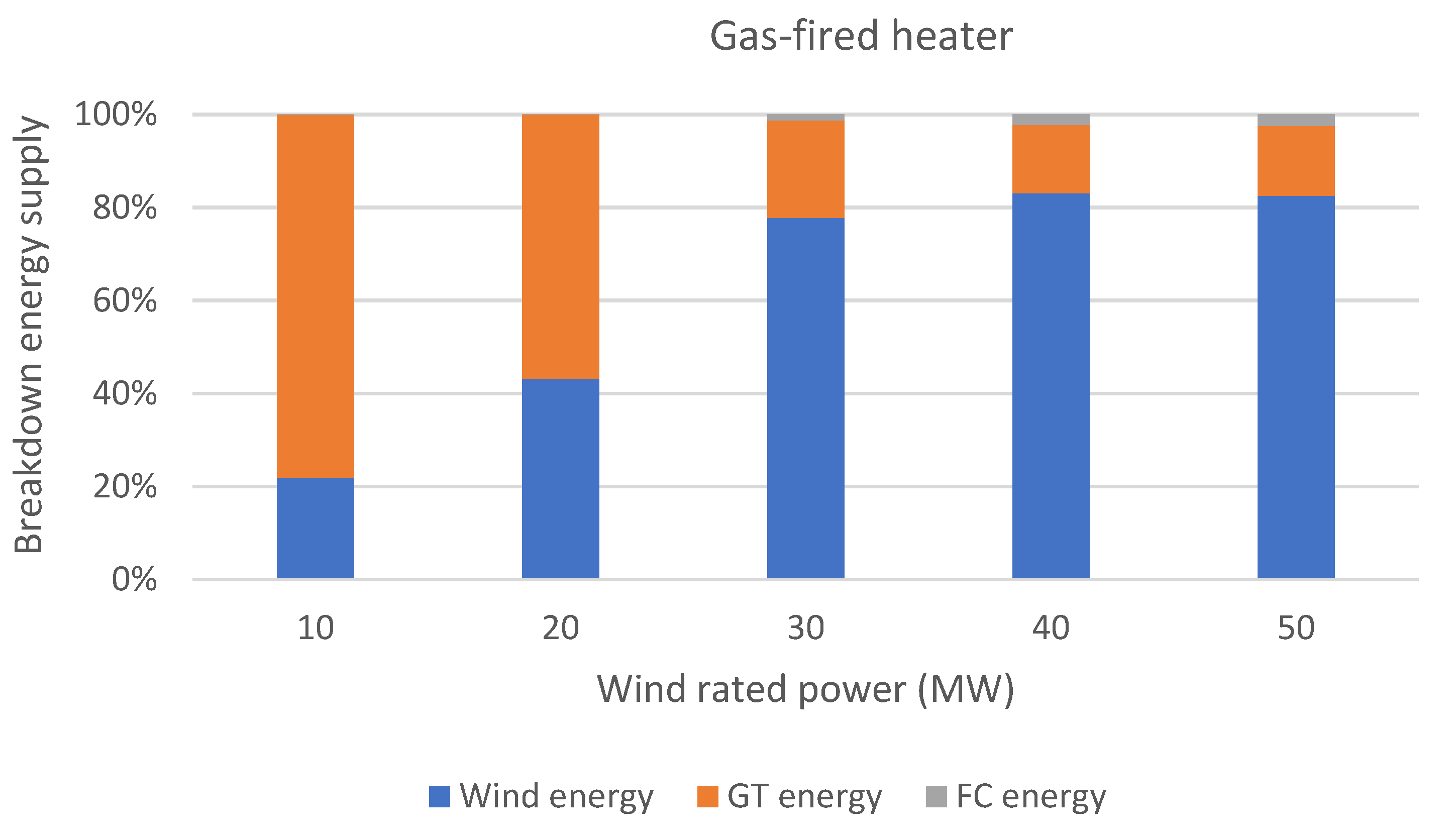
4.4. Gas-Fired Heater

A common method to produce heat offshore, whenever waste heat is not available, is to utilise gas-fired heaters. The configuration entails the combustion of a fuel gas to generate thermal energy. In this study, mixtures of methane and hydrogen are considered. The model of a gas-fired burner was developed in Thermoflow software suite [24] and its performance was tested at different compositions of the fuel gas. Simple correlations were developed and integrated into the HES model. Both hydrogen and methane usage predictions and related CO2 emissions were considered. The operating strategy implemented was to use the highest content of hydrogen in the fuel gas that allows to close the hydrogen balance and to remain within the limit of the storage size. For additional details, reference [28] is suggested.

5. Generic Offshore Installation

The aim of this study is to deliver knowledge that can be widely used in the offshore oil & gas sector. Therefore, the analysis was based on a generic case rather than on a specific offshore installation. The advantage is that the generic case study can be designed to be representative of various installations. Moreover, the design features (i.e., the energy requirements) of the case study can be manipulated to allow covering installations with different characteristics.
The generic offshore installation in the base case scenario:
  • Power demand: 30 MW;
  • Heat demand: 8 MW.
The hybrid energy system (HES):
  • Gas turbine model: LM2500 + G4;
  • Max. content of H2 in GT fuel: 22 %vol.;
  • Fuel cell stack capacity: 5 MW;
  • Electrolyser stack capacity: 10 MW;
  • H2 storage capacity: 5000 kg;
  • Wind farm power capacity: 10–50 MW.

6. Results

In this section, the results obtained are reported and discussed. The key performance indicator utilised is the cumulative value of CO2 emissions over one year of operation. The cumulative CO2 emissions are both reported in absolute and relative terms. For the latter, a baseline case is established. The basis for comparison is selected to be a simple GT cycle with WHRU (no wind power or energy storage technologies integrated), which is the most standard configuration found in offshore installations. A single LM2500 is considered unless the power requested to the GT is higher than its rated power, i.e., 33.3 MW. In the latter cases, two GTs are included, equally sharing the total load. The HES is expected to reduce the CO2 emissions when applied to cover the power and heat demand of the same generic installation. Four different methods for supplying process heat are simulated, as discussed in Section 4, and the related outputs results compared.
The simulations cover a timeline of one year, where the HES is simulated at each hour. The main variable leading to different hourly operating conditions is the wind speed, hence the wind power contribution. Conversely, the heat and power demand remain constant at the level selected for the analysis.

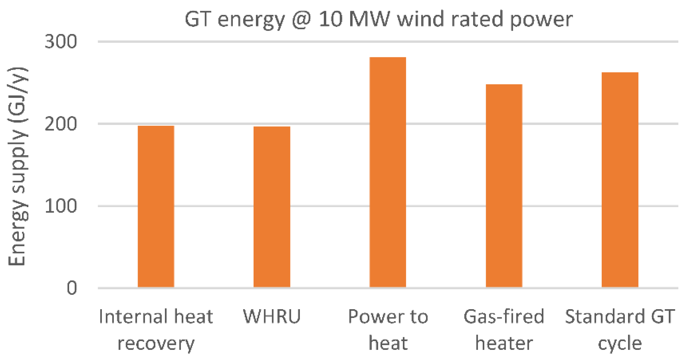
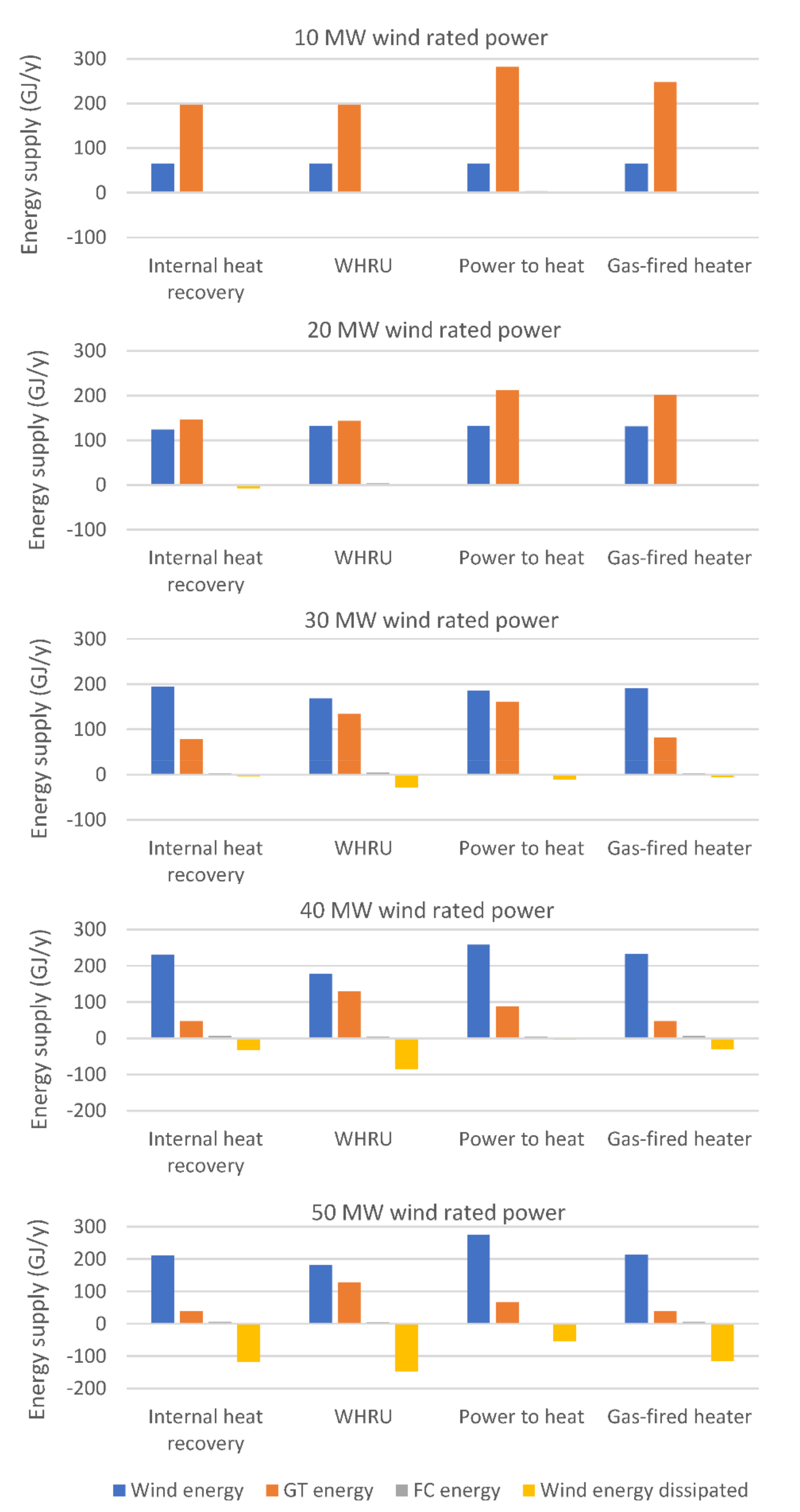
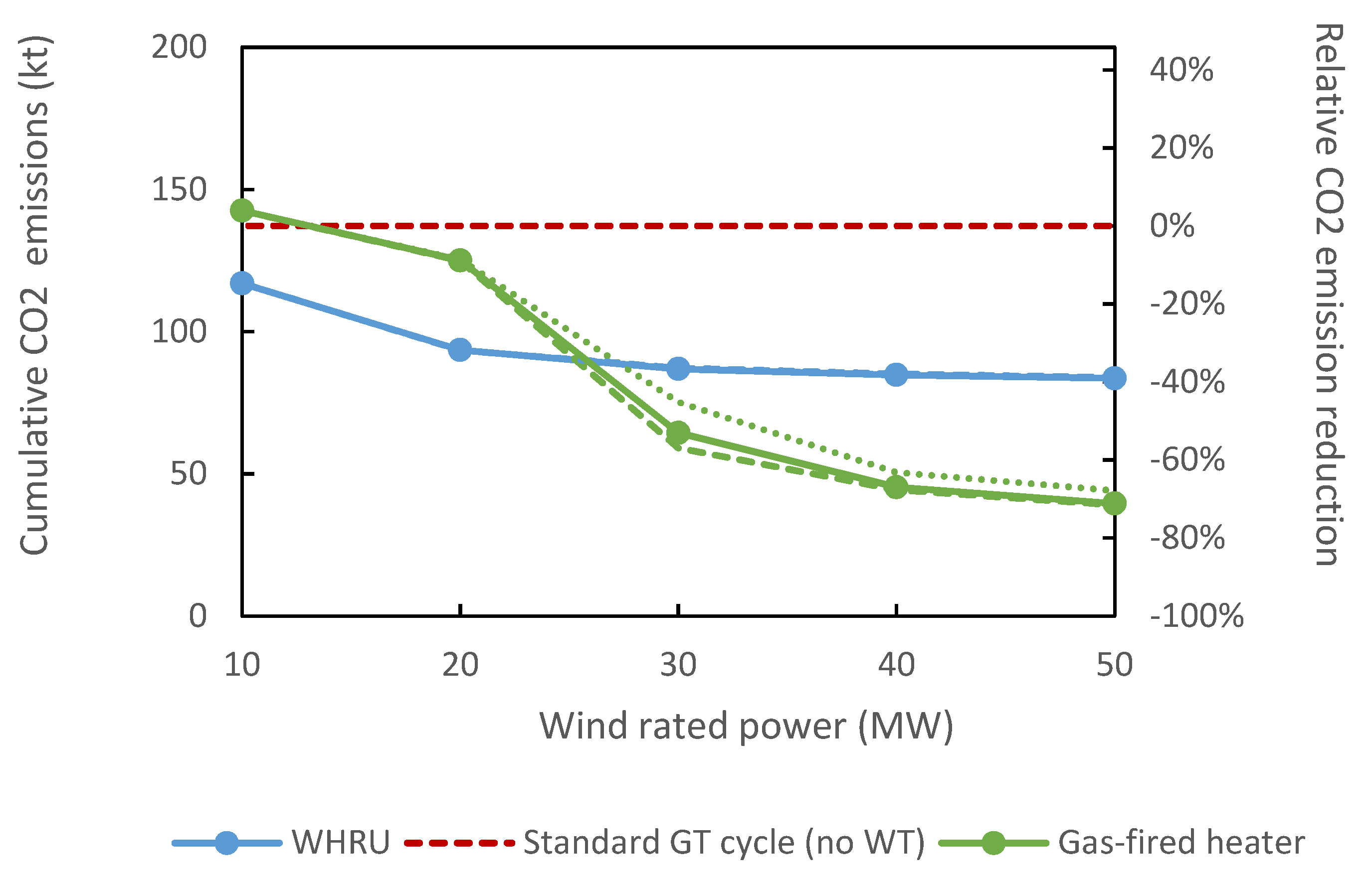
6.1. Influence of Heat Generation in the Base Case Scenario

The first analysis presented investigates the degree of decarbonisation achievable by integrating various wind power capacities. Figure 2 illustrates the results obtained in terms of cumulative CO2 emissions per one year of operation and relative CO2 emissions reductions (compared to the baseline).
The HES concepts result, as expected, in lower CO2 emissions with the relative emissions reduction increasing with the increase in the wind capacity installed. Notably, only one case led to higher emissions than the baseline: the power to heat case integrating a 10 MW wind farm. To understand this, one should realize that in the power to heat configuration, additional electric power must be supplied to cover the heat demand. The additional power requirement is slightly higher than 8 MW, due to the electric heater efficiency. When installing a 10 MW wind farm, almost the entire wind power is utilized to meet this heat demand, leaving most of the power demand to the GT. This configuration ends up being less efficient than the standard GT simple cycle that can rely on a more efficient way to produce heat (i.e., via WHRU). Figure 3 illustrates this effect by reporting the energy contribution from the GT for the various configurations tested at 10 MW wind rated power. The figure also includes the baseline with no integration of wind power (i.e., standard GT cycle). For the reasons explained, the power to heat configuration requires even more GT energy than the standard GT cycle configurations, hence resulting in a worse environmental performance.
The analysis of Figure 2 reveals that the HES relying on WHRU to meet the heat demand achieves very good performances, for low wind capacities installed (<20 MW). At higher wind capacities, the potential for decarbonisation reaches a plateau at around 40% of relative decrease. This was also observed in a previous publication [17]. Utilising a WHRU to produce heat is an energy-efficient option but necessitates the continuous utilization of GT, leading to a bulk of emissions that becomes difficult to avoid. Co-feeding H2 to the GT might partially help, but only to an extent. Conversely, the power to heat configuration shows relatively poor performance at low wind capacities installed but also a gradual improvement with larger capacities. Importantly, the potential for decarbonisation does not seem to be capped and reaches −70% CO2 emissions for a wind farm of 50 MW. It is also interesting to observe that the power to heat configuration becomes more performant with respect to the WHRU configuration when a wind farm slightly higher than 30 MW is considered. The gas-fired heater configuration displays a trend similar to that of the power to heat configuration but guarantees larger emissions cuts for medium sizes of the wind farm. The gas-fired heater configuration outperforms the WHRU configuration for wind farms larger than about 25 MW. The hydrogen share in fuel varied between 0.5 and 30% by mass, depending on the maximum amount of hydrogen that could be made available to the gas-fired heater by the storage system (larger wind power capacity normally implies larger hydrogen available as fuel for the gas-fired heater). Finally, the internal heat recovery configuration results in emissions at similar levels compared to the WHRU configuration for low wind capacities installed (<20 MW). In those instances, wind power cannot cover alone the entire power demand. A GT is always operating and thus able to provide heat via the WHRU, making additional internal heat recovery superfluous. However, while the performance of the WHRU configuration flattens out, the internal heat recovery configuration obtains a very good decrease in emissions for higher wind capacities, up to an 83% relative decrease for a wind farm of 50 MW. It should be mentioned that this configuration might not always be possible. It entails an ideal heat integration, the feasibility of which is case-specific. The above considerations are complemented by Figure 4, where a breakdown of the energy supply for the different configurations is provided. One can notice how the wind energy contribution is predictably increasing with the size of the wind farm, although at very large wind rated power the wind power that is dissipated also becomes significant. The GT energy follows an opposite trend. For the WHRU configuration, the share of energy provided by the GT decreases rapidly at low wind capacities installed but then remains quite stable when larger wind energy is made available. Conversely, the GT energy decreases more decisively at increased wind rate power for the other configurations, suggesting a more complete exploitation of the renewable resource in those instances. This is consistent with the trends from Figure 2, as the utilization of GT is the main responsible for CO2 emissions.

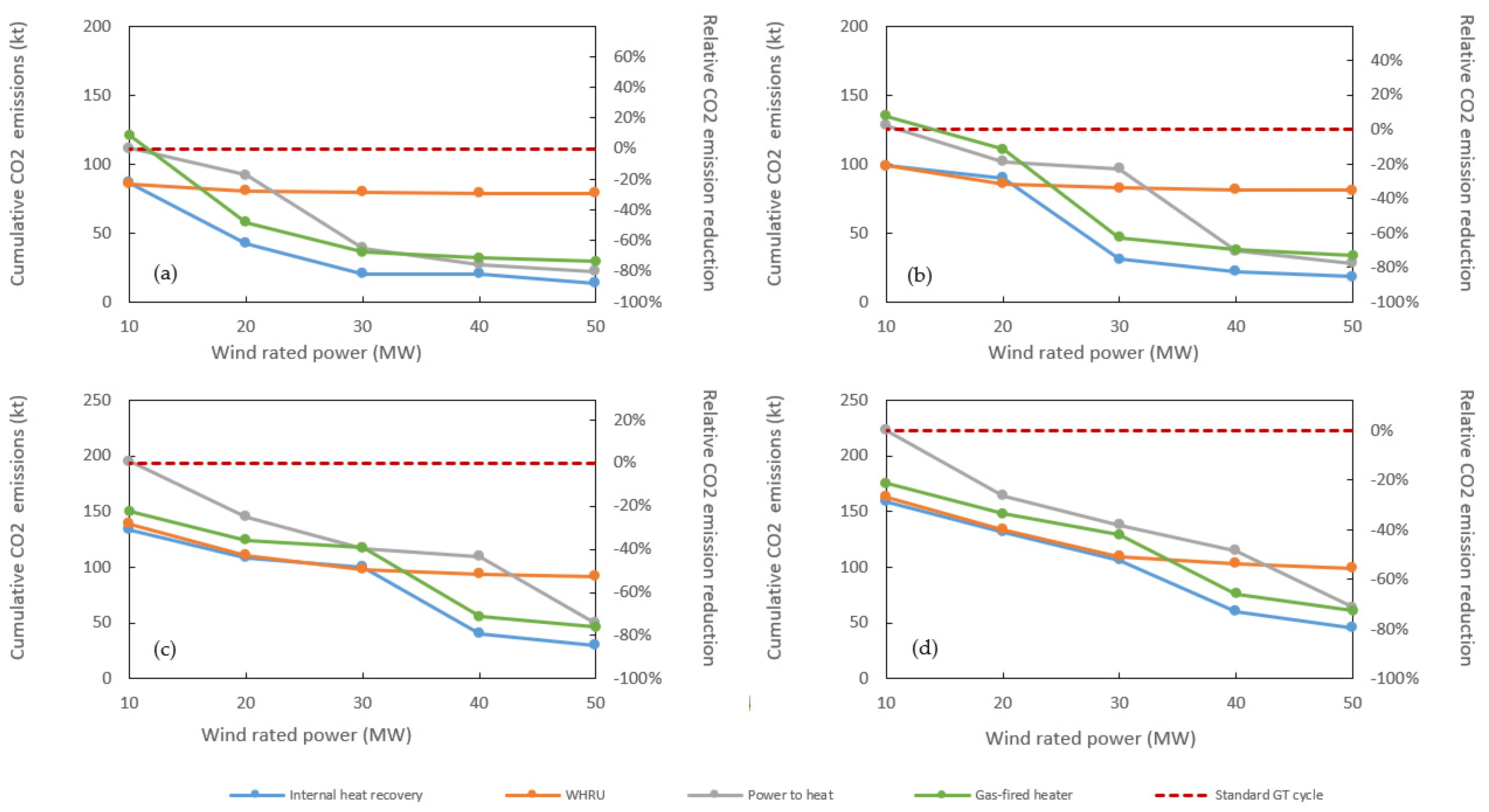
6.2. Different Heat to Power Ratios

To investigate whether the results obtained could be generalized rather than being specific to the case study considered, the same analysis was replicated for other cases. The main parameter varied was the heat to power ratio (H/P) that defines the overall energy requirement of the offshore installation. Specifically, the heat demand was kept constant at 8 MW, while the power demand was ranged between 20 MW and 40 MW:
(a)
Heat = 8 MW; Power = 20 MW; H/P = 0.40
(b)
Heat = 8 MW; Power = 25 MW; H/P = 0.32
(c)
Heat = 8 MW; Power = 35 MW; H/P = 0.23
(d)
Heat = 8 MW; Power = 40 MW; H/P = 0.20
The results obtained are illustrated in Figure 5.
Before drawing general conclusions, it is useful to provide some clarifications concerning the results reported. In the additional cases analysed, a steep change in the CO2 emissions characterizing the internal heat recovery, power to heat and gas-fired heater configurations became more evident. The reason is to be found in the relative sizing of the wind farm with respect to the total power demand. Case (b) is used as an illustrative example (power demand = 25 MW and H/P = 0.32). If the internal heat recovery or the gas-fired heater configuration is considered, the leap in CO2 emissions is located between a wind farm size of 20 MW and 30 MW. When the wind farm is 30 MW, wind power alone—at maximum capacity—is able to cover the entire power demand while, in parallel, producing some hydrogen to be used in fuel cells when the wind contribution decreases. If the wind farm size is reduced to 20 MW, the wind power is in no instance able to cover the entire power demand. In addition, little surplus power is available to produce hydrogen. This results in more limited utilization of the fuel cell stack and a larger utilization of the GT, ultimately leading to larger emissions. Similar reasoning can be applied to the power to heat configuration, bearing in mind that the actual power demand to consider increases due to the necessity to supply heat via electric heating. Hence, the leap is located at higher wind farm sizes. Figure 6, showing the shares of energy from the different sources for the gas-fired heater configuration in case (b), helps in visualizing the above considerations. The GT energy contribution decreases consistently with the increase in the size of the wind farm. However, the largest reduction (from 64% to 31%) is obtained when moving from 20 MW to 30 MW wind rated power, due to the more convenient match between the size of the wind farm and total power demand.
Given the above clarifications, one can notice how the trends are consistent throughout the different cases tested and in line with what has been discussed in the previous section. The WHRU configuration is generally convenient at low degrees of wind power integration, but its beneficial effect flattens out for larger wind farms. Conversely, the power to heat and the gas-fired heater configurations become gradually more attractive as the wind farm size increases, with the latter generally performing better between the two. The relative convenience, in terms of CO2 emissions avoided, between the various configurations tends to change with the different H/P tested. In particular, a trend could be noticed when comparing the WHRU configuration with the options based on heaters, either electric (power to heat configuration) or gas-fired (gas-fired heater configuration). At lower H/P, the WHRU configuration shows better performance until relatively high levels of installed wind power capacity (>30 MW). With the increase in the H/P considered, this threshold tends to decrease (down to <20 MW values), hence limiting the competitiveness of the WHRU configuration. As expected, the internal heat recovery configuration normally entails the overall best environmental performance reaching in several instances a relative CO2 emission cut of more than 80%.
It is also interesting to notice the impact of different H/P on the maximum CO2 emissions reduction achievable. A higher H/P is beneficial for the internal heat recovery and the power to heat configurations that reaches the highest CO2 emissions reductions for H/P equal to 0.40–88% and 80% lower CO2 emissions, respectively. These figures are down to 80% and 71% for H/P equal to 0.20. While for the power to heat configuration, an explanation can be found in the need to use a larger part of the renewable power to meet the increasing heat demand; this does not apply to the internal heat recovery configuration. In this second case, the only reason for better performance is linked to a convenient match between the size of the GT and the power demand, which, to a lesser extent, is true also for the power to heat configuration. Interestingly, the WHRU configuration features an opposite behaviour, where the highest CO2 emissions reduction (i.e., 58%) is achieved at the lowest H/P (i.e., 0.20). In this case, an increase in heat demand does not negatively affect the performance of the system as long as there is enough waste heat available in the GT flue gas. The only factor remaining to have an impact is the match between GT size and power demand. Finally, no clear trend is observed for the gas-fired heater configuration, with the relative CO2 emissions reduction remaining rather steady between 73% and 76%.

6.3. The Role of the Fuel Cell Stack

The hydrogen produced by the electrolyser stack (ELY) can be utilized either in the GT (co-feeding of natural gas and hydrogen) or in the fuel cell (FC) stack to produce power. The operational strategy implemented favours the utilization of the fuel cell as, theoretically, the “cleanest” option, having no direct CO2 emissions. However, the energy efficiency of the fuel cell (considering the entire roundtrip efficiency of ELY-FC system) is on a similar level to that of the GT. In addition, the utilization of the FC stack requires large quantities of hydrogen, which at times might be challenging to make available, given the constraints on the size of the hydrogen storage. The challenges related to an efficient utilisation of hydrogen in the FC stack can be observed in Figure 6 where the FC energy contribution is negligible in all cases studied.
Given those uncertainties in the role of the FC stack, an analysis was carried out where the HES was simulated with no FC available. Accordingly, the hydrogen produced can only be used in the GT. The results are compared to those discussed in Section 6.1 where a fuel cell stack of 5 MW was used. An additional set of simulations is also included, involving a 50% higher efficiency of the FC stack. Although such an increase in efficiency is probably out of reach even considering the expected advancements in fuel cell technology, the idea is to investigate what is the maximum room for improvement available. Figure 7 illustrates some of the simulation results. Similar trends are obtained for the internal heat recovery, power to heat and gas-fired heater configurations. Only the results from the latter are included for the sake of a clearer visualization. Conversely, the WHRU configuration showed different behaviour and it is, thus, included in the figure. The dotted lines represent the simulation outputs when no FC stack is considered. The dashed lines represent the simulation outputs when the FC stack performs 50% better than the baseline.
Not using the FC (dotted lines) generally results in higher CO2 emissions. Even though not extremely large, the difference in CO2 emissions can be relevant. For instance, up to +20%, +16% and +17% CO2 emissions are registered for the internal heat recovery, power to heat and gas-fired heater configurations, respectively. Interestingly, this trend does not apply to the WHRU configuration where the environmental performance remains almost unvaried (the dotted line is not visible as it overlaps with the full line). This points to that the role of the FC stack is in providing enough backup power to enable turning off the GT in as many instances as possible throughout the year. If the GT must be operated to supply heat, the decarbonisation obtained by hydrogen-to-fuel-cell schemes or by hydrogen-to-GT schemes is very similar.
When an improved FC efficiency is considered (dashed lines), the impact appears to be limited for all configurations. Compared to the results obtained with the baseline efficiency, a maximum reduction in CO2 emissions of 8% is achieved for either the internal heat recovery, the gas-fired heater or power to heat configuration. The differences in the case of the WHRU configuration are again negligible.
It should be noted that additional potential benefits linked to the utilization of the FC stack might exist, which are not included in the proposed analysis. For one thing, the FC stack contributes to improving grid stability, as demonstrated in a previous publication [29]. In addition, the operation of FCs is expected to make available a certain amount of waste heat [30] that could aid in achieving an internal heat recovery configuration. Lastly, while hydrogen in the FC can always be used, the utilization of hydrogen in the GT might be more constrained than what is considered in this study as it depends on the type of GT combustion system.

7. Summary and Conclusions

Offshore installations typically require both heat and power for operating, hence both forms of energy need to be decarbonised to approach very low emission levels. The paper presents a systematic analysis of suitable options to supply heat in offshore installations when implementing hybrid energy system (HES) solutions and their effect on the achievable CO2 emission reductions.
The HES system consists of a gas turbine, a wind farm, an electrolyser and fuel cell stack with hydrogen storage. Four methods to supply heat are considered for the analysis: (i) internal heat recovery from waste heat available from the processes; (ii) the utilization of a waste heat recovery unit (WHRU) harvesting heat from the flue gases of the gas turbine (GT); (iii) the utilisation of electric heaters; and (iv) the utilization of gas-fired heaters (with a methane/hydrogen mixture as fuel gas). A generic offshore installation was defined in terms of energy requirements to be the reference case for the simulations.
Harvesting heat from the exhaust of a gas turbine via a WHRU is an energy efficient solution, which delivers significant CO2 emission cuts even at relatively small wind power capacities installed. However, that involves the constant operation of a gas turbine, capping the achievable CO2 emission reduction. Indeed, despite increasing wind capacities, the potential for decarbonisation reaches a plateau at around 40% of relative decrease compared to a standard configuration not integrating renewable power. Larger CO2 emission cuts are achieved by configurations relying on a gas-fired heater or an electric heater, which both succeed to curb CO2 emissions of about 70% for a wind farm of 50 MW. Importantly, their potential for decarbonisation does not seem to be capped, opening opportunities for approaching near zero emissions. The last configuration proposed, based on internal heat recovery from offshore processes, is consistently the most effective one (up to 80% CO2 emission reduction), but its feasibility depends on the availability of sufficient waste heat and, thus, is case-specific. With respect to this, interesting opportunities might arise if thermal energy storage technologies demonstrate feasible for offshore applications.
Simulations at different heat to power ratios were conducted to confirm the obtained trends beyond the reference case study, allowing to generalise the findings of the study. In addition, the role of the fuel cell (FC) was investigated. The utilisation of hydrogen into a FC stack rather than in the GT brings limited environmental advantages with little margin of improvement connected to technology developments.
All in all, the study showed the impact of process heat on the decarbonisation potential of offshore installations by HES. Selecting a suitable method to supply process heat demonstrated essential if near-zero emissions schemes are to be pursued. These considerations are expected to hold true also for schemes involving simple integration of offshore renewable energy sources.
Future studies should include a techno-economic assessment of the concepts. Weight and space are other outputs important in offshore installations to be covered in future analyses. The aim of this paper was to investigate the CO2 emission reduction potential.

Author Contributions

Conceptualization, L.R., M.P. and L.O.N.; methodology, L.R.; software, L.R.; validation, L.R. and M.P.; formal analysis, L.R.; investigation, L.R.; resources, L.R. and M.P.; data curation, L.R.; writing—original draft preparation, L.R.; writing—review and editing, L.R., M.P. and L.O.N.; visualization, L.R. and M.P.; supervision, L.O.N.; project administration, L.O.N.; funding acquisition, L.R. and L.O.N. All authors have read and agreed to the published version of the manuscript.

Funding

This research was funded by the Research Council of Norway, grant number 281986.

Conflicts of Interest

The authors declare no conflict of interest.

References

  1. IPCC. Special Report: Global Warming of 1.5 °C; Cambridge University Press: Cambridge, UK, 2021. [Google Scholar]
  2. Statistisk Sentralbyrå Emissions to Air. Available online: https://www.ssb.no/en/natur-og-miljo/forurensning-og-klima/statistikk/utslipp-til-luft (accessed on 15 October 2021).
  3. NDC Registry—Norway. Available online: https://www4.unfccc.int/sites/NDCStaging/pages/Party.aspx?party=NOR (accessed on 15 October 2021).
  4. KonKraft. The Energy Industry Of Tomorrow On The Norwegian Continental Shelf. 2020. Available online: https://konkraft.no/wp-content/uploads/2021/04/The-energy-industry-of-tomorrow-on-the-NCS-KonKraft-report-2021-2-FINAL.pdf (accessed on 15 October 2021).
  5. Riboldi, L.; Nord, L.O. Concepts for lifetime efficient supply of power and heat to offshore installations in the North Sea. Energy Convers. Manag. 2017, 148, 860–875. [Google Scholar] [CrossRef]
  6. Pierobon, L.; Kandepu, R.; Haglind, F. Waste Heat Recovery for Offshore Applications. In Proceedings of the ASME 2012 International Mechanical Engineering Congress and Exposition, MECE2012, Houston, TX, USA, 9–15 November 2012; pp. 1–10. [Google Scholar]
  7. Van Nguyen, T.; Barbosa, Y.M.; da Silva, J.A.M.; de Oliveira Junior, S. A novel methodology for the design and optimisation of oil and gas offshore platforms. Energy 2019, 185, 158–175. [Google Scholar] [CrossRef]
  8. Riboldi, L.; Nord, L.O. Lifetime assessment of combined cycles for cogeneration of power and heat in offshore oil and gas installations. Energies 2017, 10, 744. [Google Scholar] [CrossRef] [Green Version]
  9. Mazzetti, J.M.; Nekså, P.; Walnum, H.T.; Hemmingsen, A.K.T. Energy-Efficient Technologies for Reduction of Offshore CO2 Emmissions. In Proceedings of the Offshore Technology Conference, Houston, TX, USA, 6–9 May 2013. [Google Scholar]
  10. Korpås, M.; Warland, L.; He, W.; Tande, J.O.G. A case-study on offshore wind power supply to oil and gas rigs. Energy Procedia 2012, 24, 18–26. [Google Scholar] [CrossRef] [Green Version]
  11. Riboldi, L.; Nord, L.O. Offshore Power Plants Integrating a Wind Farm: Design Optimisation and Techno-Economic Assessment Based on Surrogate Modelling. Processes 2018, 6, 249. [Google Scholar] [CrossRef] [Green Version]
  12. Oliveira-Pinto, S.; Rosa-Santos, P.; Taveira-Pinto, F. Assessment of the potential of combining wave and solar energy resources to power supply worldwide offshore oil and gas platforms. Energy Convers. Manag. 2020, 223, 113299. [Google Scholar] [CrossRef]
  13. He, W.; Jacobsen, G.; Anderson, T.; Olsen, F.; Hanson, T.; Korpås, M.; Toftevaag, T.; Eek, J.; Uhlen, K.; Johansson, E. The potential of integrating wind power with offshore oil and gas platforms. Wind Eng. 2010, 34, 125–137. [Google Scholar] [CrossRef]
  14. Riboldi, L.; Völler, S.; Korpås, M.; Nord, L.O. An Integrated Assessment of the Environmental and Economic Impact of Offshore Oil Platform Electrification. Energies 2019, 12, 2114. [Google Scholar] [CrossRef] [Green Version]
  15. Roussanaly, S.; Aasen, A.; Anatharaman, R.; Danielsen, B.; Jakobsen, J.; Heme-De-Lacotte, L.; Neji, G.; Sødal, A.; Wahl, P.E.; Vrana, T.K.; et al. Offshore power generation with CCS to decarbonise mainland electricity and offshore oil and gas installations: A techno-economic analysis. Appl. Energy 2018, in press. [Google Scholar]
  16. Riboldi, L.; Alves, E.F.; Pilarczyk, M.; Tedeschi, E.; Nord, L.O. Innovative Hybrid Energy System for stable Power and Heat Supply in offshore oil & gas Installation (HES-OFF): System Design and Grid Stability; Elsevier: Amsterdam, The Netherlands, 2020; Volume 48. [Google Scholar]
  17. Riboldi, L.; Alves, E.F.; Pilarczyk, M.; Tedeschi, E.; Nord, L.O. Optimal Design of a Hybrid Energy System for the Supply of Clean and Stable Energy to Offshore Installations. Front. Energy Res. 2020, 8, 346. [Google Scholar] [CrossRef]
  18. Nami, H.; Ertesvåg, I.S.; Agromayor, R.; Riboldi, L.; Nord, L.O. Gas turbine exhaust gas heat recovery by organic Rankine cycles (ORC) for offshore combined heat and power applications-Energy and exergy analysis. Energy 2018, 165, 1060–1071. [Google Scholar] [CrossRef]
  19. Barbosa, Y.M.; da Silva, J.A.M.; Junior, S.d.O.; Torres, E.A. Performance assessment of primary petroleum production cogeneration plants. Energy 2018, 160, 233–244. [Google Scholar] [CrossRef]
  20. Van Nguyen, T.; Fülop, T.G.; Breuhaus, P.; Elmegaard, B. Life performance of oil and gas platforms: Site integration and thermodynamic evaluation. Energy 2014, 73, 282–301. [Google Scholar] [CrossRef] [Green Version]
  21. Van Nguyen, T.; Jacyno, T.; Breuhaus, P.; Voldsund, M.; Elmegaard, B. Thermodynamic analysis of an upstream petroleum plant operated on a mature field. Energy 2014, 68, 454–469. [Google Scholar] [CrossRef] [Green Version]
  22. Chauhan, A.; Saini, R.P. A review on Integrated Renewable Energy System based power generation for stand-alone applications: Configurations, storage options, sizing methodologies and control. Renew. Sustain. Energy Rev. 2014, 38, 99–120. [Google Scholar] [CrossRef]
  23. Goldmeer, J. Fuel Flexible Gas Turbines as Enablers for a Low or Reduced Carbon Energy Ecosystem; Electrify Europe: Vienna, Austria, 2018. [Google Scholar]
  24. Thermoflow Inc. Thermoflex Version 29.0 2021; Thermoflow Inc.: Jacksonville, FL, USA, 2021. [Google Scholar]
  25. The MathWorks Inc. MATLAB R2020a 2020; The MathWorks Inc.: Natick, MA, USA, 2020. [Google Scholar]
  26. Gelaro, R.; McCarty, W.; Suárez, M.J.; Todling, R.; Molod, A.; Takacs, L.; Randles, C.A.; Darmenov, A.; Bosilovich, M.G.; Reichle, R.; et al. The Modern-Era Retrospective Analysis for Research and Applications, Version 2 (MERRA-2). J. Clim. 2021, 30, 5419–5454. [Google Scholar] [CrossRef] [PubMed]
  27. Ramadam, A. Energy Optimization of Offshore Gas Field; Norwegian University of Science and Technology: Trondheim, Norway, 2021. [Google Scholar]
  28. Lowe, C.; Brancaccio, N.; Batten, D.; Leung, C.; Waibel, D. Energy Procedia Technology Assessment of Hydrogen Firing of Process Heaters. Energy Procedia 2011, 4, 1058–1065. [Google Scholar] [CrossRef] [Green Version]
  29. Alves, E.; Sanchez, S.; Brandao, D.; Tedeschi, E. Smart load management with energy storage for power quality enhancement in wind-powered oil and gas applications. Energies 2019, 14, 2985. [Google Scholar] [CrossRef] [Green Version]
  30. Barbir, F. PEM Fuel Cells—Theory and Practice; Academic Press: Amsterdam, The Netherlands, 2005. [Google Scholar]
Figure 1. Schematic of the HES-OFF concept with additional heat solutions.
Energies 14 08123 g001
Figure 2. Absolute and relative CO2 emissions for the different configurations analysed.
Energies 14 08123 g002
Figure 3. Gas turbine (GT) energy contribution to the total energy demand for the different configurations at 10 MW wind rated power.
Energies 14 08123 g003
Figure 4. Breakdown of energy supply for the different configurations.
Energies 14 08123 g004
Figure 5. Absolute and relative CO2 emissions for the different configurations analysed and for different H/P ratios: (a) H/P = 0.40, (b) H/P = 0.32, (c) H/P = 0.23, (d) H/P = 0.20.
Energies 14 08123 g005
Figure 6. Shares of energy contributions to the overall energy demand for the gas-fired heater configuration–case (b) H/P = 0.32.
Energies 14 08123 g006
Figure 7. Absolute and relative CO2 emissions for the different options analysed: reference case (full line), without a fuel cell stack (dotted line) and with the fuel cell performance increased by 50% (dashed line).
Energies 14 08123 g007
Publisher’s Note: MDPI stays neutral with regard to jurisdictional claims in published maps and institutional affiliations.

