Article

Perovskite PV Energy Harvesting System for Uninterrupted IoT Device Applications

Department of Electrical and Computer Engineering, School of Engineering and Digital Sciences, Nazarbayev University, Kabanbay Batyr Ave. 53, Nur-Sultan 010000, Kazakhstan
*
Authors to whom correspondence should be addressed.
Energies 2021, 14(23), 7946; https://doi.org/10.3390/en14237946
Submission received: 9 October 2021 / Revised: 10 November 2021 / Accepted: 12 November 2021 / Published: 27 November 2021
(This article belongs to the Special Issue New Materials and Concepts for Solar Energy Conversion and Storage)

Abstract

:
The performance of perovskite solar cells (PSCs) has been improved throughout the years. These photovoltaic (PV) cells can be used to power Internet of Things (IoT) devices for indoor applications. A perovskite PV energy harvesting system with a stand-by battery that continuously powers an IoT device is developed in this work. The battery is required to complement the PSCs when the latter have difficulties in power delivery during low or no irradiance. The performance of the energy harvesting circuit as well as the battery charge and discharge scenarios are investigated. Voltage matching between the PSC and the battery is achieved by a boost converter. The PSC energy harvesting system uses fractional open-circuit voltage (FOCV) based maximum power point tracking (MPPT), which utilizes a Sample and Hold (S&H) circuit. The FOCV technique is based on a comparison of the perovskite PV open circuit voltages and the maximum power points. For each irradiance level, the maximum power point is unique, and this work uses a light-dependent resistor (LDR) to adjust the scaling constant in MPPT. Case studies include various scenarios under 1000 lux fluorescent light and 1 sun irradiance as well as a consideration of different battery states.

Graphical Abstract

1. Introduction

Earlier energy independence for devices is commonly achieved by using replaceable batteries. The cost of such an approach is high since batteries should be bought every time in addition to maintenance costs. According to Wojciechowski et al. [1], in Western Europe, worker payment costs about EUR 250 per hour for battery replacement.
Nowadays, the possibility of making Internet of Things (IoT) devices energy-autonomous can be realized due to recent advancements in energy sources. These technologies are based on photovoltaics (PVs), vibration, thermal, radio frequency (RF), and piezoelectric generators. There are many studies where these energy sources are used individually or as a combination in order to harvest energy for IoT applications.
PV technology is widely used to make IoT applications autonomous. There are many studies relevant to this topic, and each of them is different in terms of components and the maximum power point tracking (MPPT) techniques involved. Capacitors can take up a lot of space in micro-scale chips, whereas inductors, which are present in basic converters, may become an external component due to their large size. Charge pumps consist of switches and capacitors, and due to the absence of a large inductor, they have become the preferred choice in some of the works [2,3,4,5]. The simplicity of charge pumps has led to the limited operating voltage range, which is not present in basic converters. In micro-circuits, parasitic effects do occur and should be considered during their design. Venkatramanan and John [6] introduced the reduced-order model to handle parasitic effects. The Perturb and Observe (P&O) algorithm is one of the basic MPPTs; however, there are many other approaches and modifications of such MPPTs. Abdelmoaty et al. [7] reduced the power consumption of the circuit by modifying the Hill Climbing (HC) MPPT technique. Some researchers, such as Kantareddy et al. [8], tried using the emerging perovskite PV cells to power the sensors in battery-less applications. Such an approach could work in offices and indoors, where the light is always on. However, Kantareddy et al. [8] tested the small perovskite solar cell (PSC) under 1 sun illumination and managed to make such sensors work in the daytime, in the presence of the sun. Some authors prefer supercapacitors rather than using expensive and large batteries [3,9,10]. Supercapacitors are good for applications where a quick charge is required; however, they can store energy for a shorter time than the batteries. Batteries should be charged correctly so that they can be used longer; thus, battery management is required, as Tsai and Chen [11] proposed. Lueangamornsiri et al. [12] used the three-stage charging, which charges a battery safely and quickly. On the other hand, such a system becomes more complex with a dramatically increased number of components involved. The battery’s state-of-charge (SoC) is not considered in most of the literature, which is crucial for battery life. Moreover, energy harvesting systems can be used to feed the load and charge the battery simultaneously, whereas studies define their systems for a certain application. Table 1 demonstrates different PV-energy harvesting systems.
This work aims to develop a perovskite PV energy harvesting system for uninterrupted IoT applications. The energy harvesting system consists of the PSC, the energy harvesting circuitry, and the load management system. The IoT application is powered by the PSC and the battery. The battery charges up during excessive power generation from the PSC and discharges when the PSC generation is not enough to feed the load. The boost converter is used to match the PSC and the battery voltages. A light-dependent resistor (LDR)-assisted fractional open-circuit voltage (FOCV) MPPT with a sample and hold circuit is used to maximize the PSC energy harvest.

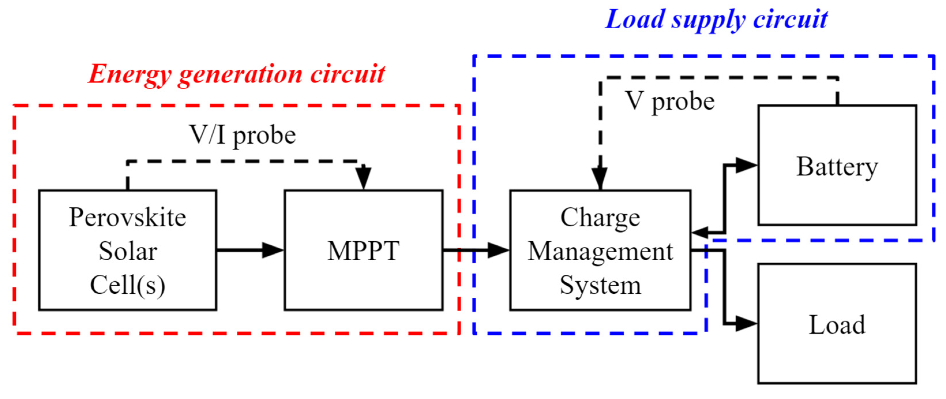
2. The Proposed Energy Harvesting System

IoT devices are small, and the energy harvesting circuit should be effective and non-complex. Figure 1 shows an illustration of the proposed perovskite PV energy harvesting system. The system consists of the energy generation circuit, the load supply circuit, and the load (IoT device). The energy generation circuitry is made up of the PSC, the MPPT, and the boost converter, while the load supply circuit comprises of the charging management system and the battery.

2.1. The Perovskite Solar Cell (PSC)

Over the past decade, the power conversion efficiency (PCE) of PSCs has increased dramatically. Their efficiency is comparable to that of the well-established conventional silicon-based PVs. Moreover, PSCs demonstrate better performance under artificial light, i.e., indoor environment, compared to the conventional silicon solar cells [13]. PSCs are composed of different functional layers which determine the performance of the device. The bandgap of Si used in PVs cannot be varied significantly, whereas the bandgap of perovskite materials can be tuned easily by modifying its compositions so that their absorption spectrum can be tailored to fit particular applications. Therefore, PSCs can be used indoors if the absorption spectrum of the perovskite material matches the indoor light spectra. The GaAs and organic PVs also demonstrate relatively good performance for indoor applications. However, GaAs is a very expensive material and organic PVs yield lower PCE compared to PSCs. Therefore, it is predicted that PSCs will become a candidate with the greatest potential in the future indoor photovoltaic (IPV) market.
The perovskite layer based on CH3NH3PbI2−xBrClx reported by Cheng et al. [14] is considered in this work. The bandgap of this perovskite material is ~1.8 eV, which is designed for indoor use [14]. The PSC model used in this work is the conventional solar cell model [4]. The parameters used in the model are adjusted to describe the perovskite PV behavior. After considering that the work of Torimtubun et al. [15] and Cheng et al. [14] employed 1000 lux of the LED (color temperature 2700 K) and 1000 lux of fluorescent light as an indoor light source, respectively, we chose to focus on an indoor light level of 1000 lux as well as 1 sun condition for comparison in this study.
In this work, three series two parallel (3s2p) connected PSCs are considered as a power source. Such a series connection increases the input voltage of the boost converter and decreases the difference with the output voltage of the boost converter [16]. The parallel connection is required to generate more current.

2.2. Boost Converter

The boost converter circuit is illustrated in Figure 2. The input voltage from the perovskite PV is increased to match the battery and load voltages. The output voltage is dependent on the duty cycle. If the MPPT is present with boost converter, the MPPT sends a pulse-width modulation (PWM) wave to drive the switch of the boost converter to set the duty cycle.

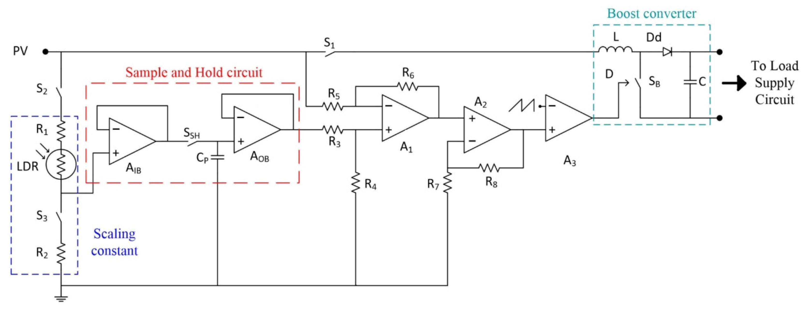
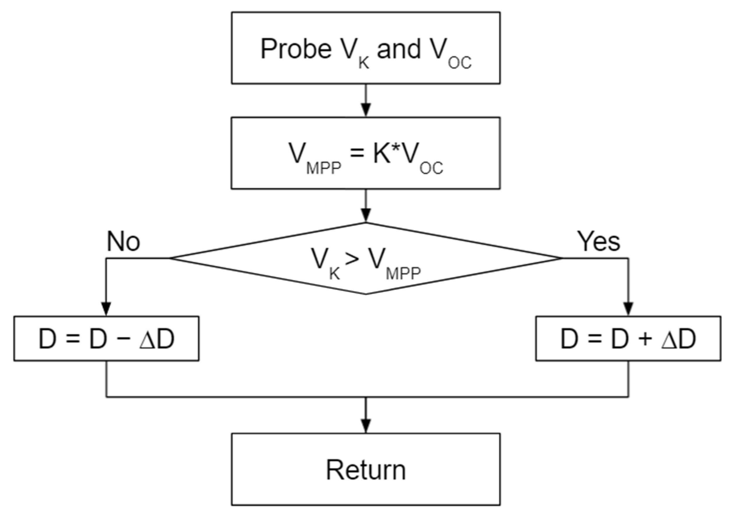
2.3. Maximum Power Point Tracking

MPPT serves to maximize the harvesting potential of the perovskite PV energy harvesting system. This work uses the FOCV MPPT approach. The proposed MPPT is based on the circuit of Leoni and Pantoli [17]. The FOCV algorithm works by adjusting the energy harvesting circuit to a maximum power point (MPP). The maximum power point voltage, VMPP, is a product of the scaling constant, K, and the probed open-circuit voltage, VOC, as shown in (1). According to Ebrahim and Mohamed [18], the value of K is in a range between 0.71 and 0.78.
VMPP = K ∗ VOC,
The flowchart of the FOCV MPPT algorithm is demonstrated in Figure 3. The VOC is probed and the VMPP value is stored in the probe capacitor. A new probe of the PSC voltage, VK, is taken to compare the probe voltage and VMPP. Depending on the difference, the duty cycle D is adjusted for a certain step ∆D.
FOCV MPPT has a capacitor, CP, to store the probe voltage value. Ahmad [19] used S&H to store the capacitor value, which is the reference value for the FOCV technique. The S&H circuit is demonstrated in Figure 2 (red zone). Switch, SSH, is closed during a probing operation, then the switch, SSH, is opened so that the FOCV MPPT can harvest the energy. AIB and AOB are op-amps in buffer configurations, which are used to hold the probe capacitor value until the next sampling period.
Huang and Kuo [20] proposed an adaptive circuit for FOCV MPPT, which adjusts the scaling constant K so that the MPP is corrected for the corresponding irradiance level. In this work, the scaling constant value, K, is adjusted using an LDR so that the MPPT is close to the harvest maximum energy out of available light.
The LDR has different resistance values under different light levels, thus, R1 and R2 in Figure 2 should be chosen carefully. In this study, the scaling constant of Figure 2 is chosen in a way as to have the maximum PSC generation indoor and under 1 sun condition. For studies that focus on varying indoor light, the scaling constant can be optimized for corresponding light levels, i.e., 1000 lux and lower light levels. The LDR is placed near the PSC, with the active surface facing the same direction as the PSC—towards the light.

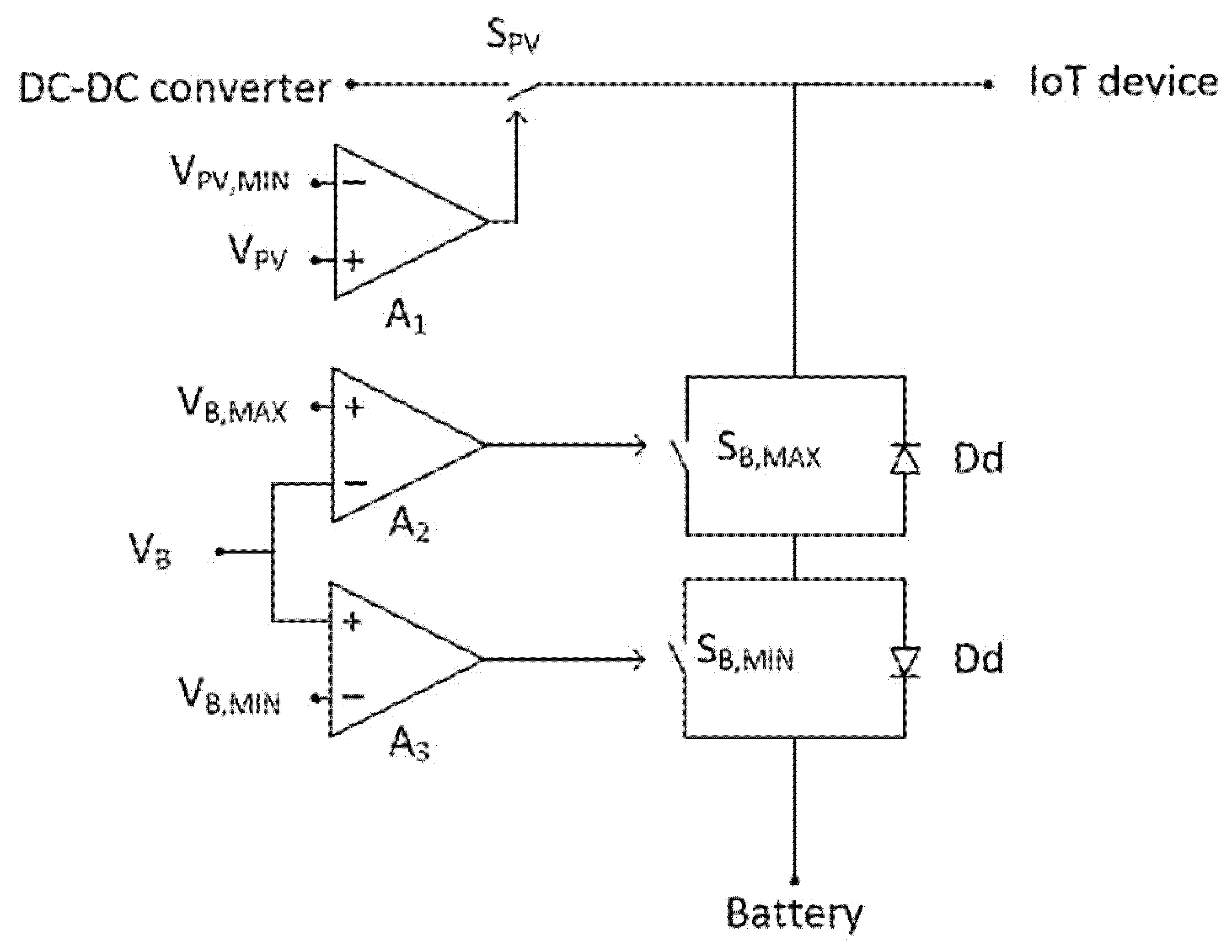
2.4. Charge Management System

The output terminal of the boost converter, as indicated in Figure 2, functions as a joint connection between the battery and the load. The joint connection is illustrated in Figure 4. The PSC is connected to the boost converter to match the voltage of the PSC with battery and load. Such a joint connection enables the battery to complement the PSC when the PV struggles to feed the load. When the PV voltage VPV is less than the reference voltage value VPV,MIN, the comparator A1 (Figure 4) sends a signal to open the switch SPV. This is performed during the period when no power is generated since there is no power coming from the DC–DC converter side.
The A2 and A3 comparators are present to restrict current flow into and out of the battery during the fully charged and discharged states. Comparator A2 opens the switch, SB,MAX, when the battery is fully charged. The reference voltage VB,MAX is used for comparison with the battery voltage at its terminal.
Comparator A3 opens the switch SB,MIN when the battery voltage is below the reference value, at which point the battery is close to a deep discharge state. Diodes are placed in such a way that the battery can be charged if SB,MIN is open, and conversely, the battery can be discharged if SB,MAX is open.
The PSC (VPV) and battery (VB) voltages are probed, whereas reference voltages VPV,MIN, VB,MIN, and VB,MAX are provided externally.

2.5. The Battery

Nowadays, portable devices use Li-ion batteries to store energy. Depending on the charging and discharging, the battery will behave as a load and power source, respectively. During excessive power generation from PV cells, the battery is charged, while the battery is discharged to complement the PVs in the absence of a light source.
The charging of the battery is controlled by a comparator. When the battery reaches its full state, the system restricts current flow to the battery. Meanwhile, the battery will be able to complement the energy source when it is required.

2.6. The Load

IoT load consumes low power; however, during transceiver operation, the energy demand of IoT systems increases significantly. To overcome such issues, modern communication technologies are optimized. Widely used IoT technologies are Long Range(LoRa)/Long Range Wide Area Network (LoRaWAN), Bluetooth Low Energy (BLE), and low power Wi-Fi. LoRa/LoRaWAN technologies can be used for long distances and have an average power consumption; thus, the IoT device in the work of Bouguera et al. [21] is adopted as a load in the current work.

3. Results

The results of the proposed energy harvesting system are discussed in this section. The perovskite PV energy harvesting system was designed in LTSpice.

3.1. Load Data

Communication technologies with low power demand are preferred since data transmission is one of the most power-hungry processes. LoRa and LoRaWAN are some of those technologies where power consumption is relatively low. Wojciechowski et al. [1] indicated that an IoT sensor sends data every 30 s to keep power consumption low for a long time. The sensing operation of such an IoT application is 12.3 mW for 25 ms, which is based on the work of Bouguera et al. [21], while power consumption is considered from the microcontroller and the sensor [21]. The power consumption of 94.2 mW for 6.5 ms occurred during data transmission; this was obtained by considering the total power consumption of the microcontroller and the transceiver [21]. After the sensing and transmission operation, the IoT device switches to sleep mode with a 10 µW consumption [21].

3.2. Perovskite PV Solar Cell

In this work, the PSC circuit model is represented by a conventional PV model, which has a current source, diode, and series and shunt resistances [4]. Table 2 summarizes the PV data used for simulation in the behavioral model based on the experimental work of Cheng et al. [14]. The current source generates a current, which is a product of the short-circuit current density, JSC, and the area, A, of the PSC. The diode saturation current is adjusted to have the desired VOC for each irradiance level. To feed the IoT application chosen for this work, 3 series 2 parallel (3s2p) connected PSCs were used, with an area of 2.25 cm2 and 0.01 cm2 under 1000 lux fluorescent light and 1 sun for each PSC, respectively.

3.3. Battery

In this work, a 35 mAh Li-ion battery model was created according to Golubev [22]. The battery had a similar behavior to its larger, commercially available versions. The battery was used within the operating voltage range of 3.7–4.2 V. Thus, such a battery could feed the load of 100–130 mW safely.

3.4. Boost Converter

Table 3 contains boost converter parameters, which were calculated according to equations that Mohammad and Devaraj [23] used, for 1000 lux and 1 sun light levels.
A boost converter with a resistive load was used in this work. The light level was 1000 lux, the duty cycle was set at 50%, a 110 Ohm load, a 3s2p PSC connection, and with each PSC having an area of 2.25 cm2. The capacitor of the boost converter provided power to the load only during half of the period, when the switch was closed (Figure 5a). In Figure 5a, it can be seen that the capacitor current during the boost converter operation is irregular, and simulation results have shown that increasing the calculated capacitor value by 1000 times (from the initial value of 9.35 nF) results in an expected current graph (blue), as in regular boost converters. The calculated values of the boost converter capacitors were in the 9.35 nF scale, and increasing it by 1000 times changed it to 9.35 µF.
Figure 5b represents the inductor (blue), diode (green), and capacitor (red) currents of a boost converter. The currents illustrate the expected behavior, where the inductor current charges and discharges depending on the duty cycle state (on and off, respectively). The diode current is present when the switch is off; consequently, the inductor is discharged. The capacitor also charges when the switch is off, and discharges when the switch is closed.

4. Case Studies and Discussion

There are two irradiance levels for the PSC—1000 lux and 1 sun, representing indoor and outdoor environments, respectively. The parameters of PSCs are adjusted for the corresponding irradiance level. The battery is in a half-charged and a discharged state for different scenarios. The LDR has resistance according to the light level. For the performance analysis of the proposed perovskite PV energy harvesting system in this work, three scenarios were considered as case studies based on the PSC and battery states.

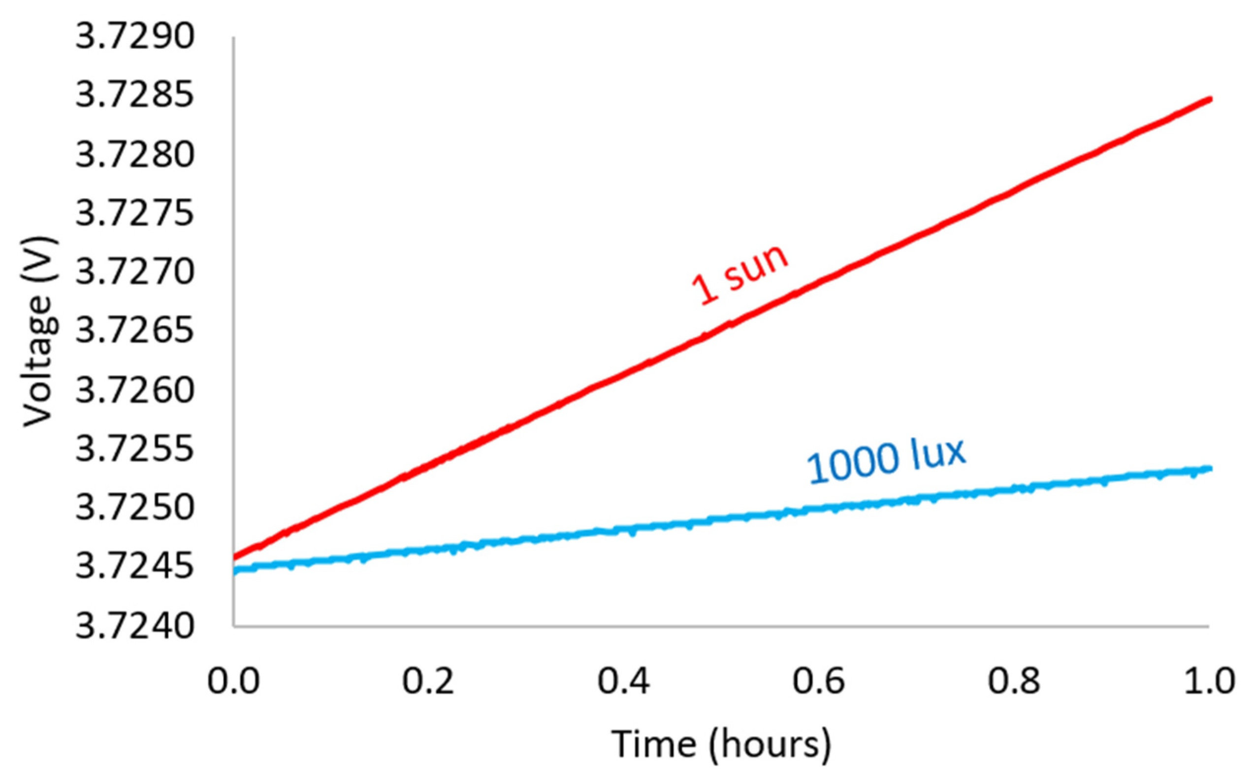
4.1. Scenario 1: 1 Sun Condition

In this scenario, the irradiance level was 1 sun. Figure 6a illustrates the output power (green) of the charger, the battery charge/discharge (blue), and the load consumption (red). After the probing period of 3 ms, the load had a consumption of 12.3 mW, i.e., a power consumption of 1.8 mW for the microcontroller and 10.5 mW for the sensor, for 25 ms. Further load consumption increased to 94.2 mW, i.e., power consumptions of 1.8 mW for the microcontroller and 92.4 mW for the transceiver, for 6.5 ms [21]. Then, the load was switched to sleep mode when a current of 10 µA was consumed. When the PSC generation was not enough to feed the load (e.g., shading), the battery was discharged to assist the charger with load feeding. The simulation included switches that caused ripples, as in Figure 6.

4.2. Scenario 2: 1000 Lux Indoor Light Level

This scenario had lower PSC generation (green) and a non-full battery. Figure 6b is similar to Figure 6a; however, in this scenario, PSC generation (green) was much lower and the battery (blue) discharged more in order to assist the PSC (green) with load (red) feeding. Since the load had peak consumption of a short duration every 30 s, the energy harvesting system had time to feed the battery. PSC generation was enough to feed the load, which was in sleep mode. The excess power of the charger went to the battery.
Figure 7 demonstrates battery voltage increase under 1 sun and 1000 lux light levels. Since the PSC charger had a higher generation at 1 sun, the battery voltage increased faster than at 1000 lux.

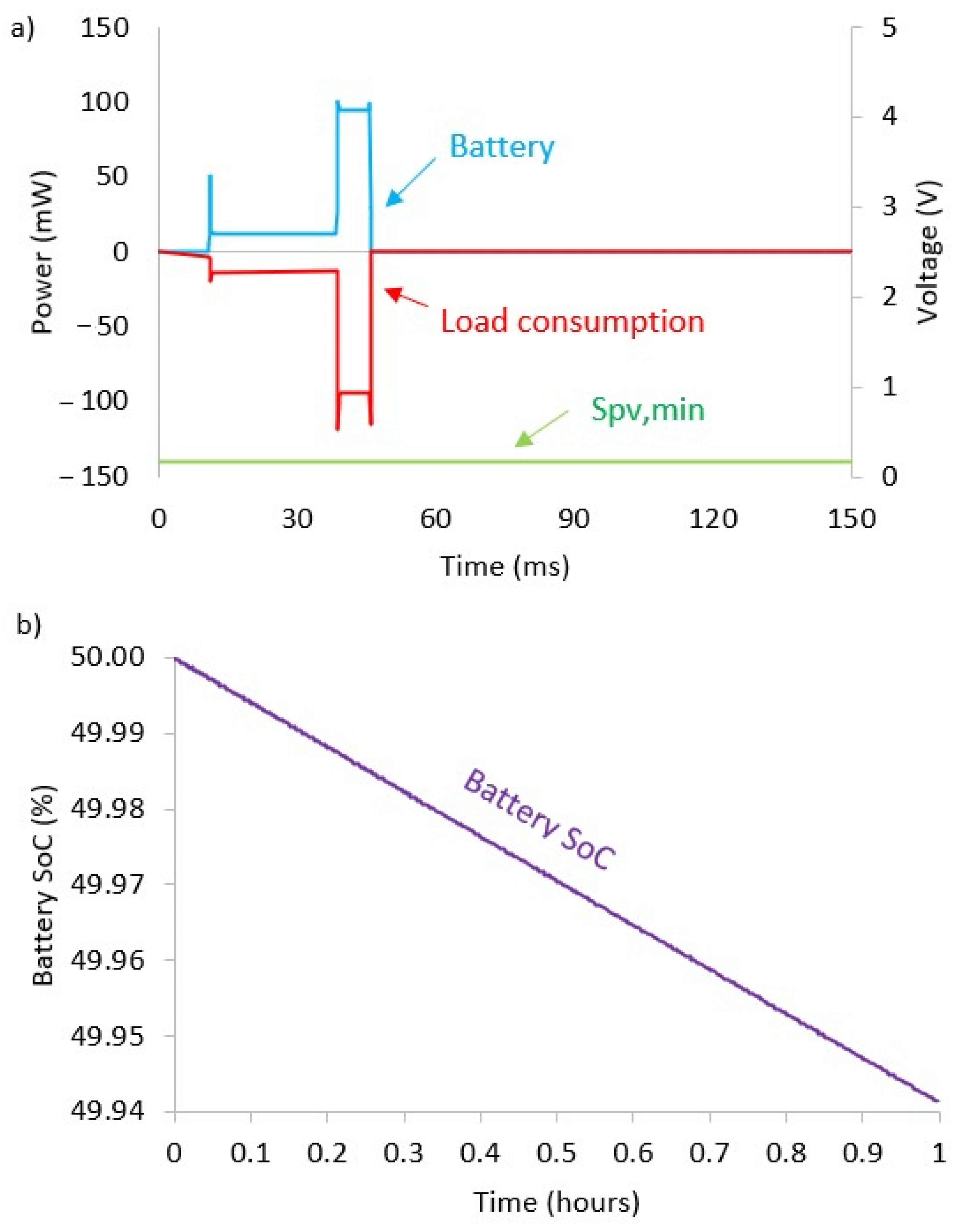
4.3. Scenario 3: Battery Discharging

This case occurred when there was an absence of PSC generation and a non-full battery. Such a scenario usually happens during the night. Figure 8a illustrates how the battery (blue) discharges to feed the load (red). The switch SPV,MIN (green) is in an open state, which indicates that PSC generation is not happening and the MPPT part of the energy harvesting circuit is disconnected.
Figure 8b demonstrates the battery SoC (purple) for the same load for a one-hour simulation. Initially, the battery was at 50% charge, and at the end of the simulation, the charge of the battery decreased to ~49.94%.
This work used FOCV MPPT techniques to maximize PSC generation. The energy harvesting circuit required reference values to be used in comparison steps, and a saw-tooth generator to create the pulse width modulation (PWM) wave in order to control the duty cycle of the boost converter. On the other hand, there is no need for a memory unit or a microchip.
The LDR is described in the light-dependent resistor section. This work focused on the use of 1000 lux fluorescent light and 1 sun irradiance, and the LDR changes scaling constant. For 1000 lux, VMPP was 2.25 V for the 3s2p configuration, where the VMPP to VOC ratio was 0.75. In the case of 1 sun for the same configuration, the VMPP was at 2.744 V, and the VMPP to VOC ratio was 0.82.
The MPPs between these points were closer than LDR-less circuits; hence, part of the losses was reduced. Moreover, the LDR was a single component and did not increase the number of components in the charger circuit as did the chip-based adaptive techniques. In addition to the ready-to-use advantage of the LDR, this component could be placed near PSCs as an external part. On the other hand, an LDR has a slow response time, which potentially restricts its use in fast-tracking applications.

5. Conclusions

In this work, we developed a PSC energy harvesting system for continuous IoT applications. Simulations were performed using PSCs and battery models. The charger was based on LDR-assisted FOCV MPPT with S&H and a charging management system. The FOCV approach was chosen due to its simplicity and a small number of components. The S&H circuit was included to decrease the deviation of the probe capacitor value during MPPT operation. The LDR was used for the passive adjustments of MPP for different light levels. The case studies demonstrated the expected energy harvesting behavior for different scenarios. The energy harvesting circuit could potentially be used for indoor IoT applications. Along with the advancement of technologies, modern communication techniques such as LoRa/LoRaWAN, Bluetooth low energy, and low power WiFi have optimized the power consumption of transceiver operations. Therefore, in the future, relatively smaller high-efficiency PSCs and thin-film batteries, even those with low capacitance, would be sufficient for IoT applications due to their lower power consumption as compared to the load described in this work.

Author Contributions

Y.O. contributed to the design, methodology, validating, and editing of the manuscript; A.N. contributed to the review and editing of the manuscript; I.A.U. contributed to the conceptualization, review, and editing of the manuscript. All authors have read and agreed to the published version of the manuscript.

Funding

This work was supported by Scientific and Technical Projects (AP08856931), funded by the Ministry of Education and Science of the Republic of Kazakhstan, and Nazarbayev University (grant no. 021220CRP0422, 110119FD4506).

Institutional Review Board Statement

Not applicable.

Informed Consent Statement

Not applicable.

Data Availability Statement

Not applicable.

Conflicts of Interest

The authors declare no conflict of interest.

References

  1. Wojciechowski, K.; Forgács, D.; Rivera, T. Industrial Opportunities and Challenges for Perovskite Photovoltaic Technology. Sol. RRL 2019, 3, 1900144. [Google Scholar] [CrossRef]
  2. Liu, X.; Huang, L.; Ravichandran, K.; Sanchez-Sinencio, E. A Highly Efficient Reconfigurable Charge Pump Energy Harvester with Wide Harvesting Range and Two-Dimensional MPPT for Internet of Things. IEEE J. Solid-State Circuits 2015, 51, 1302–1312. [Google Scholar] [CrossRef]
  3. Cheng, Y.P.; Chao, P.C.P.; Men, G.Y.; Yang, C.C.; Wang, T.W. An 80% effeciency and highly adaptable PV energy harvest circuitry with MPPT for IOT devices. In Proceedings of the IEEE Sensors 2017, Glasgow, Scotland, 30 October–1 November 2017; pp. 1–33. [Google Scholar] [CrossRef]
  4. Mondal, S.; Paily, R. On-Chip Photovoltaic Power Harvesting System with Low-Overhead Adaptive MPPT for IoT Nodes. IEEE Internet Things J. 2017, 4, 1624–1633. [Google Scholar] [CrossRef]
  5. Eltaliawy, A.; Mostafa, H.; Ismail, Y. Microscale solar energy harvesting for wireless sensor networks based on exponential maximum power locking technique. In Proceedings of the IEEE International Conference on Electronics, Circuits, and Systems, Abu Dhabi, United Arab Emirates, 8–11 December 2013. [Google Scholar] [CrossRef]
  6. Venkatramanan, D.; John, V. Dynamic Modeling and Analysis of Buck Converter based Solar PV Charge Controller for Improved MPPT Performance. In Proceedings of the 2018 IEEE International Conference on Power Electronics, Drives and Energy Systems, PEDES 2018, Indian Institute of Technology Madras, Chennai, Tamilnadu, India, 18–21 December 2018. [Google Scholar] [CrossRef] [Green Version]
  7. Abdelmoaty, A.A.; Al-Shyoukh, M.; Hsu, Y.C.; Fayed, A.A. A MPPT circuit with 25 μw power consumption and 99.7% tracking efficiency for PV systems. IEEE Trans. Circuits Syst. I Regul.Pap. 2016, 64, 272–282. [Google Scholar] [CrossRef]
  8. Kantareddy, S.N.R.; Mathews, I.; Sun, S.; Layurova, M.; Thapa, J.; Correa-Baena, J.P.; Bhattacharyya, R.; Buonassisi, T.; Sarma, S.E.; Peters, I.M. Perovskite PV-Powered RFID: Enabling Low-Cost Self-Powered IoT Sensors. IEEE Sens. J. 2020, 20, 471–478. [Google Scholar] [CrossRef] [Green Version]
  9. Simjee, F.; Chou, P.H. Everlast: Long-life, supercapacitor-operated wireless sensor node. In Proceedings of the International Symposium on Low Power Electronics and Design, Tegernsee, Germany, 4–6 October 2006; pp. 197–202. [Google Scholar] [CrossRef]
  10. Habibzadeh, M.; Hassanalieragh, M.; Soyata, T.; Sharma, G. Supercapacitor-based embedded hybrid solar/wind harvesting system architectures. In Proceedings of the International System on Chip Conference, Munich, Germany, 5–8 September 2017; pp. 215–220. [Google Scholar] [CrossRef]
  11. Tsai, T.H.; Chen, K. A 3.4mW photovoltaic energy-harvesting charger with integrated maximum power point tracking and battery management. In Proceedings of the Digest of Technical Papers-IEEE International Solid-State Circuits Conference, San Francisco, CA, USA, 17–21 February 2013; Volume 56, pp. 72–73. [Google Scholar] [CrossRef]
  12. Lueangamornsiri, T.; Thongpull, K.; Chalermyanont, K.; Wichakool, W. Design and development of a stand-alone solar energy harvesting system by MPPT and quick battery charging. In Proceedings of the 2016 13th International Conference on Electrical Engineering/Electronics, Computer, Telecommunications and Information Technology (ECTI-CON), Chiang Mai, Thailand, 28 June—1 July 2016; pp. 1–5. [Google Scholar] [CrossRef]
  13. Mathews, I.; Kantareddy, S.N.; Buonassisi, T.; Peters, I.M. Technology and Market Perspective for Indoor Photovoltaic Cells. Joule 2019, 3, 1415–1426. [Google Scholar] [CrossRef]
  14. Cheng, R.; Chung, C.C.; Zhang, H.; Liu, F.; Wang, W.T.; Zhou, Z.; Wang, S.; Djurišić, A.B.; Feng, S.-P. Tailoring Triple-Anion Perovskite Material for Indoor Light Harvesting with Restrained Halide Segregation and Record High Efficiency Beyond 36%. Adv. Energy Mater. 2019, 9, 1901980. [Google Scholar] [CrossRef] [Green Version]
  15. Torimtubun, A.A.A.; Sanchez, J.G.; Pallares, J.; Marsal, L.F. Photostability Study of Inverted Polymer Solar Cells under AM 1.5G and LED Illumination via Impedance Spectroscopy. IEEE J. Electron Devices Soc. 2021, 9, 484–491. [Google Scholar] [CrossRef]
  16. Xu, J.; Chen, Y.; Dai, L. Efficiently photo-charging lithium-ion battery by perovskite solar cell. Nat. Commun. 2015, 6, 1–7. [Google Scholar] [CrossRef] [PubMed] [Green Version]
  17. Leoni, A.; Pantoli, L. SPICE Model Identification Technique of a Cheap Thermoelectric Cell Applied to DC/DC Design with MPPT Algorithm for Low-Cost, Low-Power Energy Harvesting. Appl. Sci. 2019, 9, 3744. [Google Scholar] [CrossRef] [Green Version]
  18. Ebrahim, M.A.; Mohamed, R.G. Comparative Study and Simulation of Different Maximum Power Point Tracking (MPPT) Techniques Using Fractional Control & Grey Wolf Optimizer for Grid Connected PV System with Battery. In Electric Power Conversion; IntechOpen: London, UK, 2019. [Google Scholar] [CrossRef] [Green Version]
  19. Ahmad, J. A fractional open circuit voltage based maximum power point tracker for photovoltaic arrays. In Proceedings of the ICSTE 2010-2010 2nd International Conference on Software Technology and Engineering, San Juan, PR, USA, 3–5 October 2010; Volume 1. [Google Scholar] [CrossRef]
  20. Huang, P.C.; Kuo, T.H. A 100-pA Adaptive-FOCV MPPT Circuit with >99.6% Tracking Efficiency for Indoor Light Energy Harvesting. In Proceedings of the 2019 IEEE Asian Solid-State Circuits Conference, A-SSCC 2019, Macau, Macao, 4–6 November 2019; pp. 185–188. [Google Scholar] [CrossRef]
  21. Bouguera, T.; Diouris, J.-F.; Chaillout, J.-J.; Jaouadi, R.; Andrieux, G. Energy Consumption Model for Sensor Nodes Based on LoRa and LoRaWAN. Sensors 2018, 18, 2104. [Google Scholar] [CrossRef] [PubMed] [Green Version]
  22. Golubev, I. 01 Li 18650 LTspice Model. Демoнстрация мoдели литиевoгo аккумулятoр в LTspice.—YouTube. Available online: https://www.youtube.com/watch?v=Yf5AFVeXstQ&list=PLwDnwfIPmS9n2bJegfw1arAKW1eAZJx2a (accessed on 3 October 2021).
  23. Mohammed, S.S.; Devaraj, D. Simulation and Analysis of stand-alone photovoltaic system with boost converter using MATLAB/Simulink. In Proceedings of the 2014 International Conference on Circuits, Power and Computing Technologies, ICCPCT 2014, Nagercoil, India, 20–21 March 2014; pp. 814–821. [Google Scholar] [CrossRef]
Figure 1. The proposed perovskite PV energy harvesting system.
Energies 14 07946 g001
Figure 2. The proposed FOCV MPPT circuit.
Energies 14 07946 g002
Figure 3. Flowchart of the FOCV algorithm.
Energies 14 07946 g003
Figure 4. Charging Management System circuit.
Energies 14 07946 g004
Figure 5. The boost converter simulation: (a) comparison of the boost converter capacity value and the capacity value increased by 1000 times, (b) simulation of PV-powered boost converter with resistive load.
Energies 14 07946 g005
Figure 6. PSC energy harvesting system simulations for (a) 1 sun and (b) 1000 lux light levels. The green line represents PSC generation, the blue line—battery charge/discharge, and the red line—the load.
Energies 14 07946 g006
Figure 7. The battery voltage during energy harvesting at 1 sun (red) and 1000 lux (blue) light levels.
Energies 14 07946 g007
Figure 8. The charger simulation during no power generation: (a) the charger behavior and (b) battery discharge for one hour.
Energies 14 07946 g008
Table 1. Comparison of the literature and this work.
Aspect[3][6][7][8][11]This Work
Application
(the object fed by the energy harvesters)
SupercapacitorBatteryLoadRFID sensorBatteryCombined battery and load
Converter typeCross-coupled charge pumpBuckUnknownNo converterBoostBoost
SoC checkNoNoNoNoYesYes
NoveltyLarge range of throughput power, indoor applicationDetailed analysis of the small-signal modelThree-Point Hill-Climbing MPPT algorithmPSC powered battery-less low power RFID sensorMPPT with high conversion efficiency and battery managementSimultaneous charge management for battery and load, LDR-assisted FOCV, and use of PSCs
Table 2. PV data used in the simulation.
Light LevelShort-Circuit
Current Density,
JSC (mA)
Series
Resistance,
RS (Ωcm2)
Parallel
Resistance,
RP (kΩ)
Area,
A (cm2)
1000 lux0.128130074.862.25
1 sun16.509.001.500.10
Table 3. Calculated boost converter parameters.
Light LevelInput Voltage,
VIN (V)
Output
Voltage,
VOUT (V)
Output
Current,
IOUT (mA)
Inductor,
L (mH)
Capacitor,
C (nF)
1000 lux2.254.200.2764.52.98
1 sun2.744.201.1314.09.35
Publisher’s Note: MDPI stays neutral with regard to jurisdictional claims in published maps and institutional affiliations.

