
Thermodynamic Insight in Design of Methanation Reactor with Water Removal Considering Nexus between CO2 Conversion and Irreversibilities


 and
and
Abstract
:1. Introduction
2. Model Development
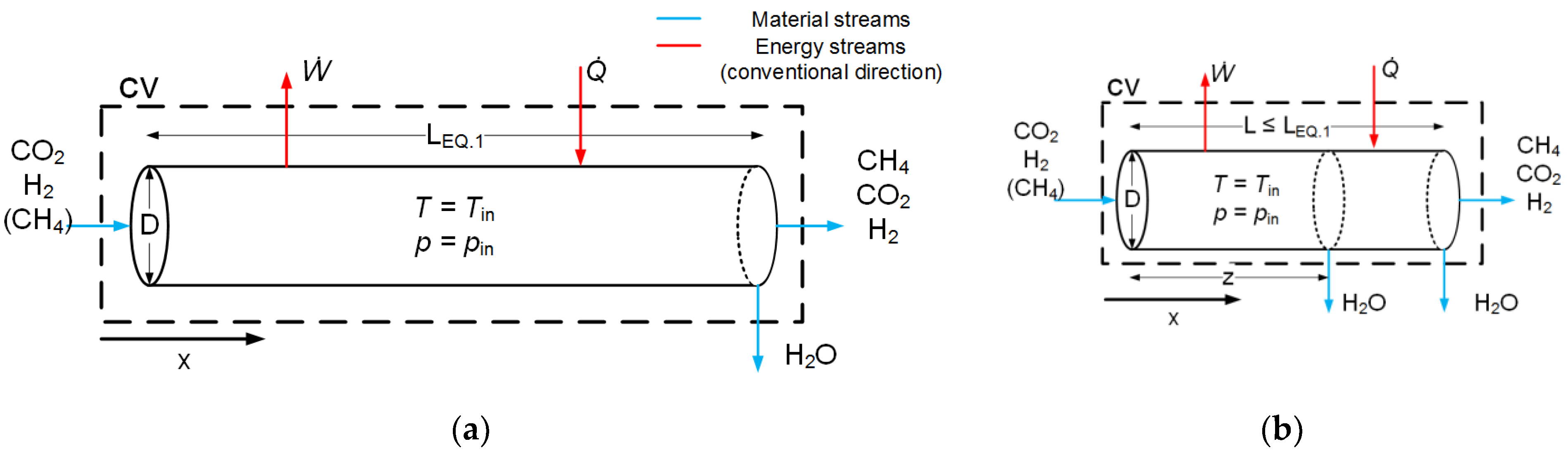
2.1. Reactor Modeling
2.2. Reaction Kinetics
2.3. Effectiveness Factor
2.4. Numerical Solution Strategy
3. Methodology
4. Results
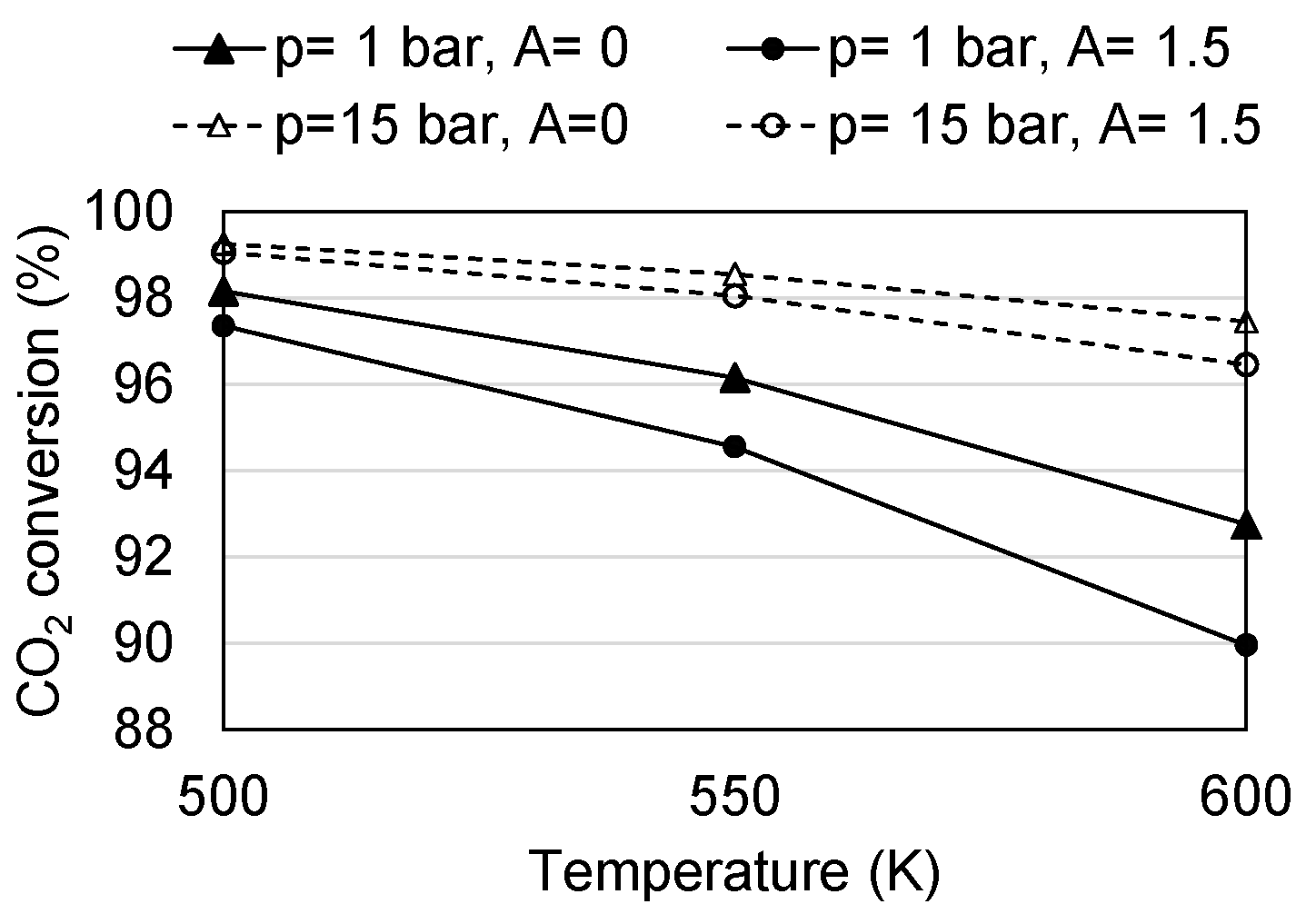
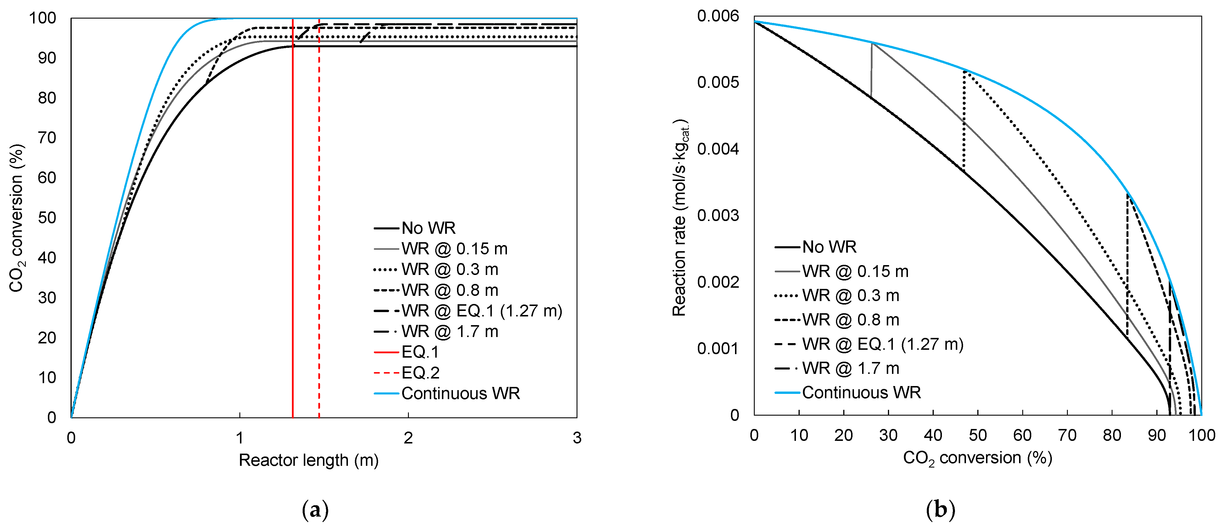
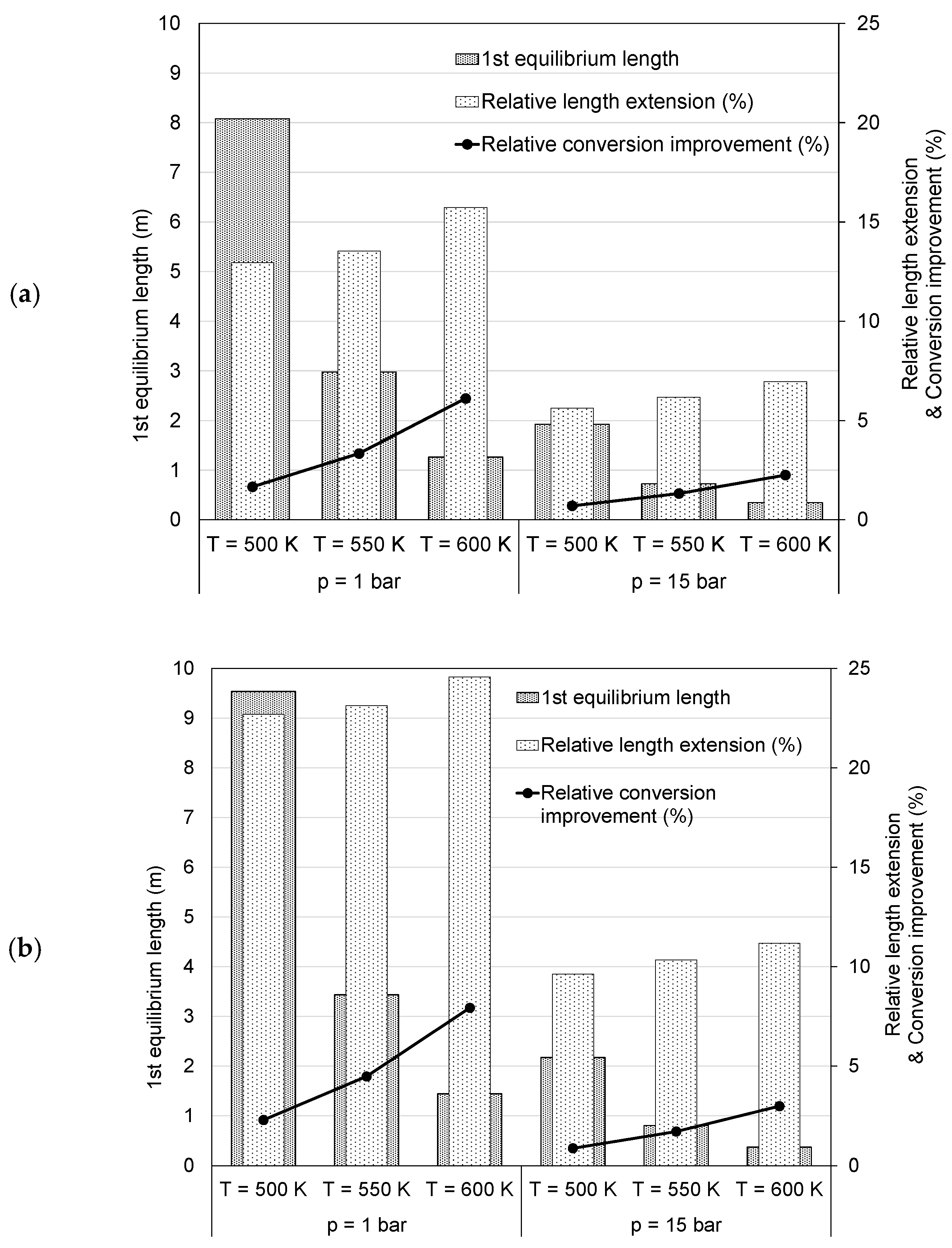
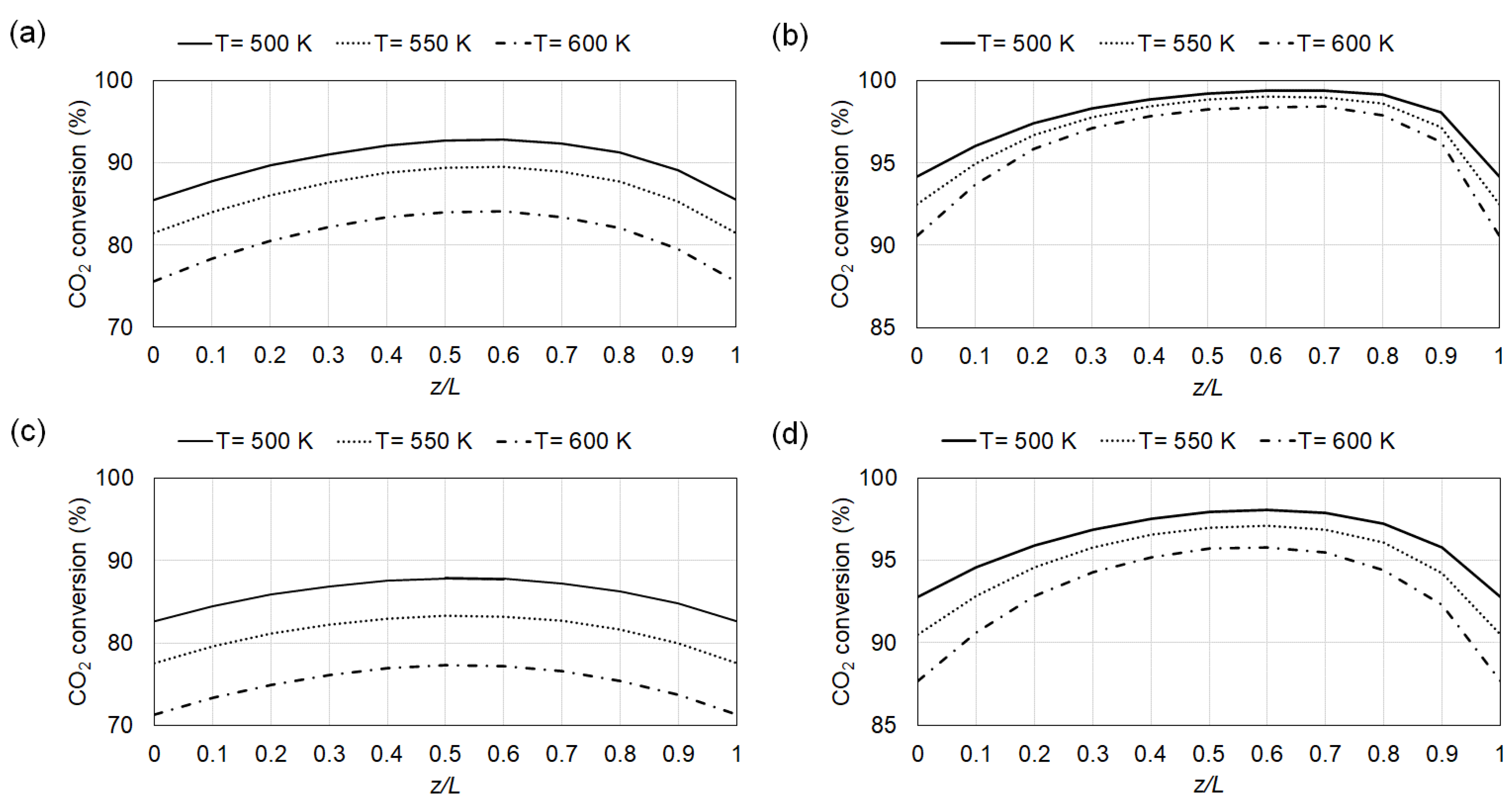
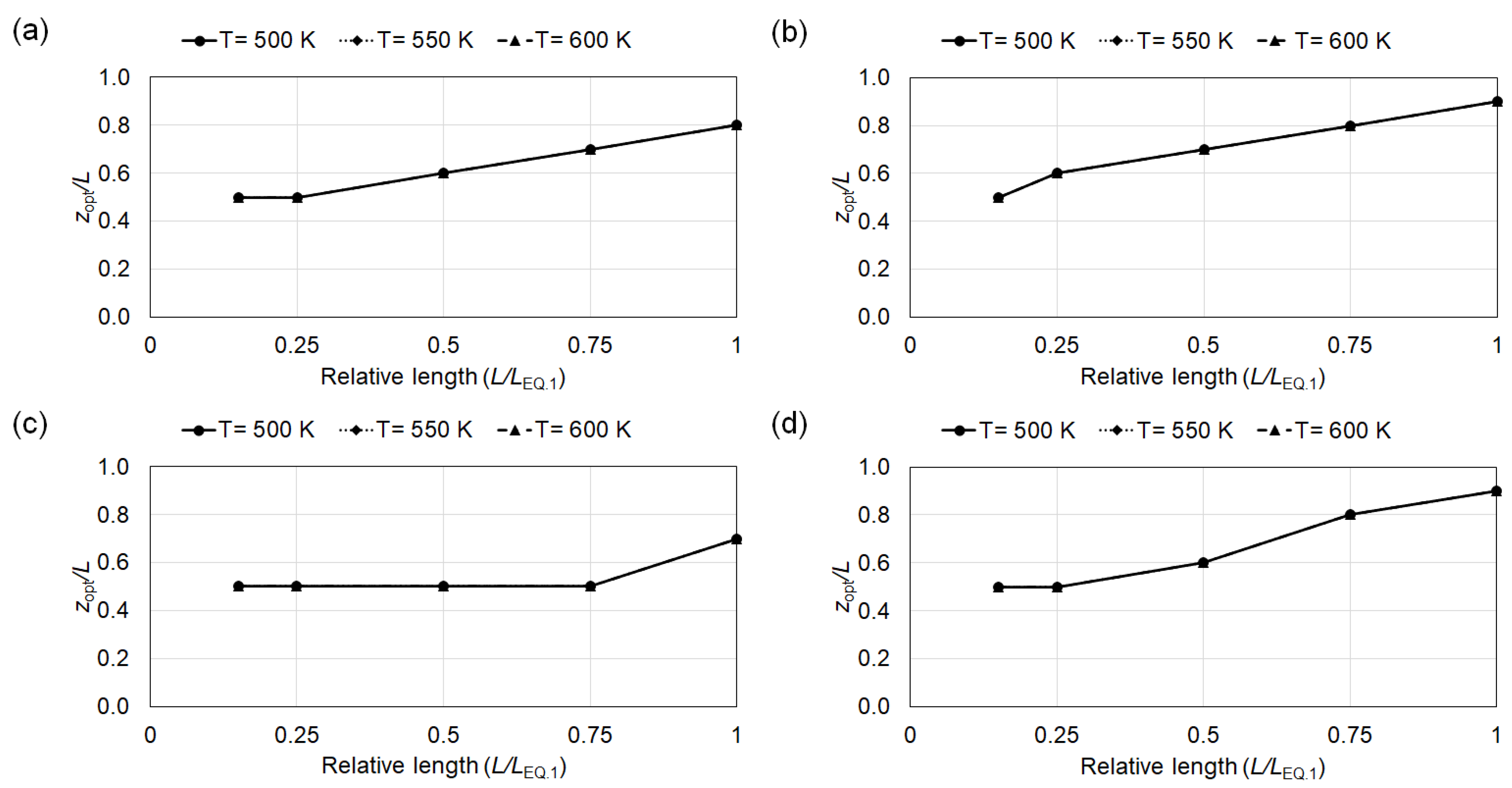
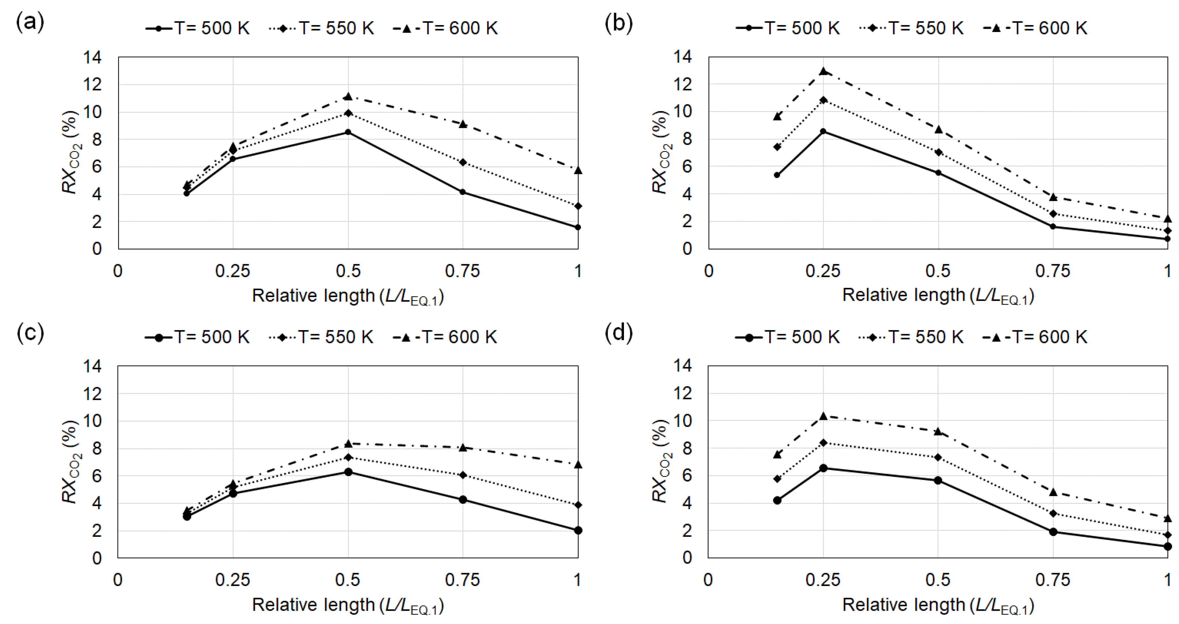
4.1. Conversion
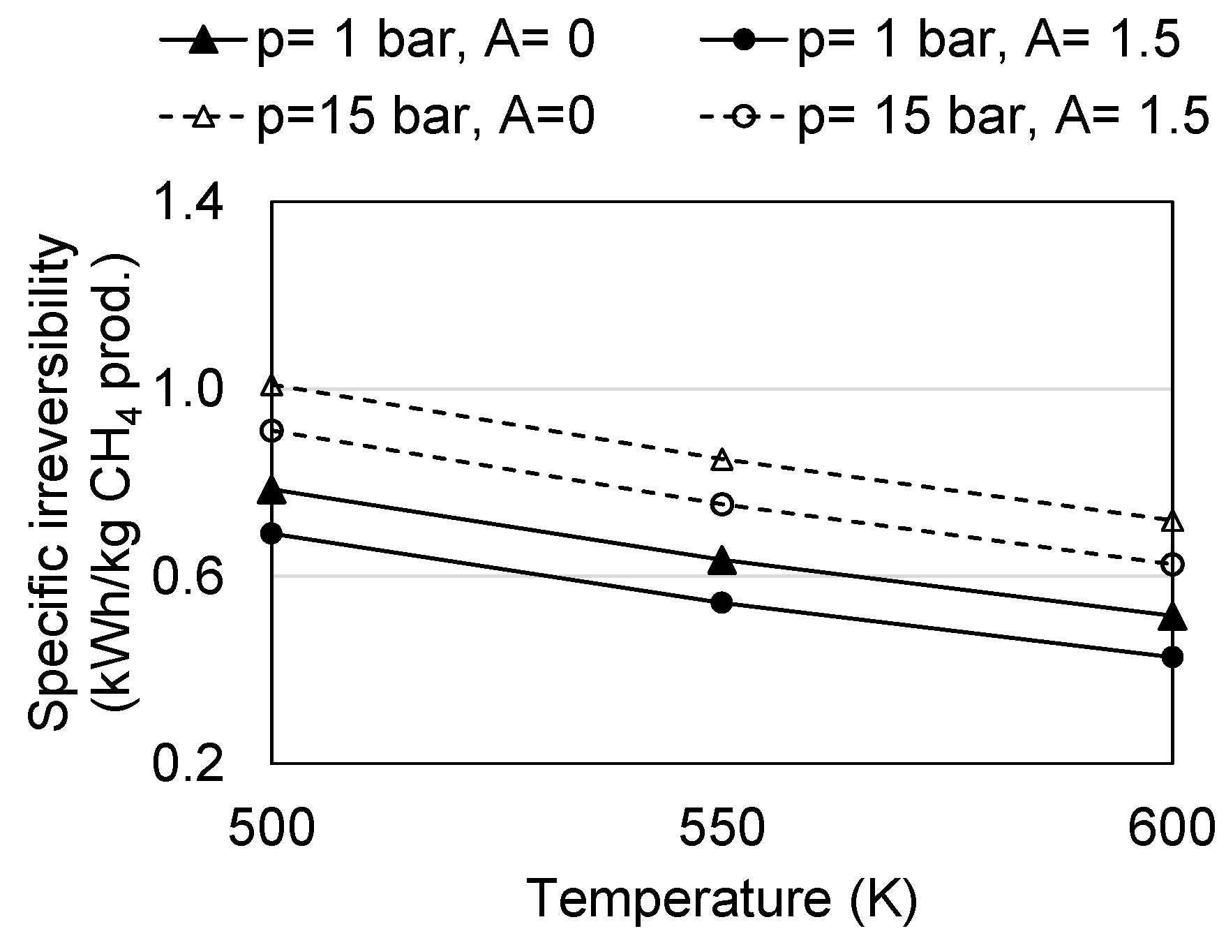
4.2. Irreversibility
5. Remarks
6. Conclusions
Author Contributions
Funding
Institutional Review Board Statement
Informed Consent Statement
Data Availability Statement
Acknowledgments
Conflicts of Interest
References
- He, W.; Abbas, Q.; Alharthi, M.; Mohsin, M.; Hanif, I.; Vo, X.V.; Taghizadeh-Hesary, F. Integration of renewable hydrogen in light-duty vehicle: Nexus between energy security and low carbon emission resources. Int. J. Hydrogen Energy 2020, 45, 27958–27968. [Google Scholar] [CrossRef]
- Pao, H.T.; Tsai, C.M. CO2 emissions, energy consumption and economic growth in BRIC countries. Energy Policy 2010, 38, 7850–7860. [Google Scholar] [CrossRef]
- Balsalobre-Lorente, D.; Shahbaz, M.; Roubaud, D.; Farhani, S. How economic growth, renewable electricity and natural resources contribute to CO2 emissions? Energy Policy 2018, 113, 356–367. [Google Scholar] [CrossRef] [Green Version]
- Sinsel, S.R.; Riemke, R.L.; Hoffmann, V.H. Challenges and solution technologies for the integration of variable renewable energy sources—A review. Renew. Energy 2020, 145, 2271–2285. [Google Scholar] [CrossRef]
- Gallo, A.B.; Simões-Moreira, J.R.; Costa, H.K.M.; Santos, M.M.; Moutinho dos Santos, E. Energy storage in the energy transition context: A technology review. Renew. Sustain. Energy Rev. 2016, 65, 800–822. [Google Scholar] [CrossRef]
- Parra, D.; Valverde, L.; Pino, F.J.; Patel, M.K. A review on the role, cost and value of hydrogen energy systems for deep decarbonization. Renew. Sustain. Energy Rev. 2019, 101, 279–294. [Google Scholar] [CrossRef]
- Ghaib, K.; Ben-Fares, F.Z. Power-to-Methane: A state-of-the-art review. Renewable Sustainable Energy Rev. 2018, 81, 433–446. [Google Scholar] [CrossRef]
- Uebbing, J.; Rikho-Struckmann, L.K.; Sunmacher, K. Exergetic assessment of CO2 methanation processes for the chemical storage of renewable energies. Appl. Energy 2019, 233, 271–282. [Google Scholar] [CrossRef]
- Massa, F.; Coppola, A.; Scala, F. A thermodynamic study of sorption-enhanced CO2 methanation at low pressure. J. CO2 Util. 2020, 35, 176–184. [Google Scholar] [CrossRef]
- Mazza, A.; Bompard, E.; Chicco, G. Applications of power to gas technologies in emerging electrical systems. Renew. Sustain. Energy Rev. 2018, 92, 794–806. [Google Scholar] [CrossRef]
- Sabatier, P.; Senderens, J.B. New Synthesis of Methane. C. R. Hebd. Séances Acad. Sci. 1902, 134, 514–516. [Google Scholar]
- Rönsch, S.; Schneider, J.; Matthischke, S.; Schlüter, M.; Götz, M.; Lefebvre, J.; Prabhakaran, P.; Bajhor, S. Review on methanation—From fundamentals to current projects. Fuel 2016, 166, 276–296. [Google Scholar] [CrossRef]
- Ngo, S.I.; Lim, Y.I.; Lee, D.; Go, K.S.; Seo, M.W. Flow behaviors, reaction kinetics, and optimal design of fixed- and fluidized-beds for CO2 methanation. Fuel 2020, 275, 117886. [Google Scholar] [CrossRef]
- Kao, Y.L.; Lee, P.H.; Tseng, Y.T.; Chien, I.L.; Ward, J.D. Design, control and comparison of fixed-bed methanation reactor systems for the production of substitute natural gas. J. Taiwan Inst. Chem. Eng. 2014, 45, 2346–2357. [Google Scholar] [CrossRef]
- Schlereth, D.; Hinrichsen, O. A fixed-bed reactor modeling study on the methanation of CO2. Chem. Eng. Res. Des. 2014, 92, 702–712. [Google Scholar] [CrossRef]
- Fache, A.; Marias, F.; Guerré, V.; Palmade, S. Optimization of fixed-bed methanation reactors: Safe and efficient operation under transient and steady-state conditions. Chem. Eng. Sci. 2018, 192, 1124–1137. [Google Scholar] [CrossRef]
- Bremer, J.; Sundmacher, K. Operation range extension via hot-spot control for catalytic CO2 methanation reactors. React. Chem. Eng. 2019, 4, 1019–1037. [Google Scholar] [CrossRef] [Green Version]
- Zimmermann, R.T.; Bremer, J.; Sundmacher, K. Optimal catalyst particle design for flexible fixed-bed CO2 methanation reactors. Chem. Eng. J. 2020, 387, 123704. [Google Scholar] [CrossRef]
- Kopyscinski, J.; Schildhauer, T.J.; Biollaz, S.M.A. Methanation in a fluidized bed reactor with high initial CO partial pressure: Part II—Modeling and sensitivity study. Chem. Eng. Sci. 2011, 66, 1612–1621. [Google Scholar] [CrossRef]
- Herce, C.; Cortés, C.; Stendardo, S. Numerical simulation of a bubbling fluidized bed reactor for sorption-enhanced steam methane reforming under industrially relevant conditions: Effect of sorbent (dolomite and CaO-Ca12Al14O33) and operational parameters. Fuel Process. Technol. 2019, 186, 137–148. [Google Scholar] [CrossRef]
- Li, J.; Zhou, L.; Li, P.; Zhu, Q.; Jiajian, G.; Gu, F.; Su, F. Enhanced fluidized bed methanation over a Ni/Al2O3 catalyst for production of synthetic natural gas. Chem. Eng. J. 2013, 219, 183–189. [Google Scholar] [CrossRef]
- Meng, F.; Li, X.; Li, M.; Cui, X.; Zhong, L. Catalytic performance of CO methanation over La-promoted Ni/Al2O3 catalyst in a slurry-bed reactor. Chem. Eng. J. 2017, 313, 1548–1555. [Google Scholar] [CrossRef]
- Lefebvre, J.; Bajohr, S.; Kolb, T. Modeling of the transient behavior of a slurry bubble column reactor for CO2 methanation, and comparison with a tube bundle reactor. Renew. Energy 2020, 151, 118–136. [Google Scholar] [CrossRef]
- Lefebvre, J.; Götz, M.; Bajohr, S.; Reimert, R.; Kolb, T. Improvement of three-phase methanation reactor performance for steady-state and transient operation. Fuel Process. Technol. 2015, 132, 83–90. [Google Scholar] [CrossRef]
- Engelbrecht, N.; Chiuta, S.; Everson, R.C.; Neomagus, H.W.J.P.; Bessarabov, D.G. Experimentation and CFD modelling of a microchannel reactor for carbon dioxide methanation. Chem. Eng. J. 2017, 313, 847–857. [Google Scholar] [CrossRef]
- Mathieu-Potvin, F.; Gosselin, L. Threshold length for maximal reaction rate in catalytic microchannels. Chem. Eng. J. 2012, 188, 86–97. [Google Scholar] [CrossRef]
- Hashemi, S.E.; Lien, K.M.; Schnell, S.K.; Austbø, B. Thermodynamic analysis of different methanation reactors for biogas upgrading. Comput. Aided Chem. Eng. 2020, 48, 367–372. [Google Scholar] [CrossRef]
- Sun, D.; Khan, F.M.; Simakov, D.S.A. Heat removal and catalyst deactivation in a Sabatier reactor for chemical fixation of CO2: Simulation-based analysis. Chem. Eng. J. 2017, 329, 165–177. [Google Scholar] [CrossRef]
- Sun, D.; Simakov, D.S.A. Thermal management of a Sabatier reactor for CO2 conversion into CH4: Simulation-based analysis. J. CO2 Util. 2017, 21, 368–382. [Google Scholar] [CrossRef]
- Kiewidt, L.; Thöming, J. Predicting optimal temperature profiles in single-stage fixed-bed reactors for CO2-methanation. Chem. Eng. Sci. 2015, 132, 59–71. [Google Scholar] [CrossRef]
- Faria, A.C.; Miguel, C.V.; Rodrigues, A.E.; Madeira, L.M. Modeling and Simulation of a Steam-Selective Membrane Reactor for Enhanced CO2 Methanation. Ind. Eng. Chem. Res. 2020, 59, 16170–16184. [Google Scholar] [CrossRef]
- Kampen, J.V.; Boon, J.; Berkel, F.V.; Vente, J.; Annaland, M.V.S. Steam separation enhanced reactions: Review and outlook. Chem. Eng. J. 2019, 374, 1286–1303. [Google Scholar] [CrossRef]
- Diban, N.; Aguayo, A.T.; Bilbao, J.; Urtiaga, A.; Ortiz, I. Membrane Reactors for in Situ Water Removal: A Review of Applications. Ind. Eng. Chem. Res. 2013, 52, 10342–10354. [Google Scholar] [CrossRef]
- Walspurger, S.; Elzinga, G.D.; Dijkstra, J.W.; Sarić, M.; Haije, W.G. Sorption enhanced methanation for substitute natural gas production: Experimental results and thermodynamic considerations. Chem. Eng. J. 2014, 242, 379–386. [Google Scholar] [CrossRef] [Green Version]
- Faria, A.C.; Miguel, C.V.; Madeira, L.M. Thermodynamic analysis of the CO2 methanation reaction with in-situ water removal for biogas upgrading. J. CO2 Util. 2018, 26, 271–280. [Google Scholar] [CrossRef]
- Najari, S.; Gróf, G.; Saeidi, S. Enhancement of hydrogenation of CO2 to hydrocarbons via In-Situ water removal. Int. J. Hydrogen Energy 2019, 44, 24759–24781. [Google Scholar] [CrossRef]
- Hillestad, M. Systematic staging in chemical reactor design. Chem. Eng. Sci. 2010, 65, 3301–3312. [Google Scholar] [CrossRef]
- Fischer, K.L.; Langer, M.R.; Freund, H. Dynamic carbon dioxide methanation in a wall-cooled fixed bed reactor: Comparative evaluation of reactor models. Ind. Eng. Chem. Res. 2019, 58, 19406–19420. [Google Scholar] [CrossRef]
- Lohmuller, R.; Schneider, H.; Watson, A. Methanation Process. U.S. Patent US4294932A, 13 October 1981. [Google Scholar]
- Fogler, H.S. Essentials of Chemical Reaction Engineering; Prentice Hall: Upper Saddle River, NJ, USA, 2011. [Google Scholar]
- Koschany, F.; Schlereth, D.; Hinrichsen, O. On the kinetics of the methanation of carbon dioxide on coprecipitated NiAl(O)x. Appl. Catal. B Environ. 2016, 181, 504–516. [Google Scholar] [CrossRef]
- Lunde, P.J.; Kester, F.L. Carbon dioxide methanation on a Ruthenium catalyst. Ind. Eng. Chem. Process Des. Dev. 1974, 13, 27–33. [Google Scholar] [CrossRef]
- Aparicio, L.M. Transient Isotopic Studies and Microkinetic Modeling of Methane Reforming over Nickel Catalysts. J. Catal. 1997, 165, 262–274. [Google Scholar] [CrossRef]
- Kee, R.J.; Coltin, M.E.; Glarborg, P.; Zhu, H. Chemically Reacting Flow: Theory, Modeling, and Simulation, 2nd ed.; John Wiley & Sons: Hoboken, NJ, USA, 2018; Chapter 3. [Google Scholar] [CrossRef]
- Fuller, E.N.; Schettler, P.D.; Giddings, J.C. New method for prediction of binary gas-phase diffusion coefficients. Ind. Eng. Chem. 1966, 58, 18–27. [Google Scholar] [CrossRef]
- Kotas, T.J. The Exergy Method of Thermal Plant Analysis; Exergon Publishing Company: London, UK, 2012. [Google Scholar]

| Variable | Tref | kref | Ea | KOH,ref | ΔHOH | KH2,ref | ΔHH2 | Kmix,ref | ΔHmix |
|---|---|---|---|---|---|---|---|---|---|
| Unit | K | mol/bar·s·kgcat | kJ/mol | bar−0.5 | kJ/mol | bar−0.5 | kJ/mol | bar−0.5 | kJ/mol |
| Value | 555 | 3.46·10−1 | 77.5 | 0.5 | 22.4 | 0.44 | −6.2 | 0.88 | −10 |
| Parameter | Unit | Value | Ref. |
|---|---|---|---|
| Temperature range | K | 500–600 | [41] |
| Pressure range | bar | 1–15 | [41] |
| Catalyst density | kg/m3 | 2355.2 | [41] |
| Catalyst void fraction | - | 0.4 | [17] |
| H2/CO2 ratio | - | 4 | - |
| CH4/CO2 ratio range | - | 0–1.5 | - |
| Inlet CO2 molar flow rate | mol/s | 0.002 | - |
| Tube diameter | m | 0.0254 | - |
| Catalyst diameter | m | 0.002 | [17] |
| Catalyst pore diameter | nm | 10 | [17] |
| Catalyst porosity | - | 0.6 | [17] |
| Catalyst tortuosity | - | 2 | [17] |
| Ambient temperature | K | 298.15 | - |
| Ambient pressure | bar | 1.01325 | - |
| x | XCO2 | ||||
|---|---|---|---|---|---|
| (m) | (%) | (kWh/kg CH4 Prod.) | (kWh/kg CH4 Prod.) | (kWh/kg CH4 Prod.) | (kWh/kg CH4 Prod.) |
| No WR | 92.9 | 1.976 | 1.560 | 0.098 | 0.514 |
| 0.15 | 94.2 | 1.972 | 1.560 | 0.155 | 0.567 |
| 0.3 | 95.3 | 1.968 | 1.560 | 0.166 | 0.574 |
| 0.8 | 97.6 | 1.958 | 1.560 | 0.132 | 0.530 |
| 1.27 * | 98.4 | 1.954 | 1.560 | 0.109 | 0.502 |
| 1.7 | 98.4 | 1.954 | 1.560 | 0.109 | 0.502 |
| Continuous WR | 100.0 | 1.942 | 1.560 | 0.678 | 1.060 |
Publisher’s Note: MDPI stays neutral with regard to jurisdictional claims in published maps and institutional affiliations. |
© 2021 by the authors. Licensee MDPI, Basel, Switzerland. This article is an open access article distributed under the terms and conditions of the Creative Commons Attribution (CC BY) license (https://creativecommons.org/licenses/by/4.0/).
Share and Cite
Hashemi, S.E.; Lien, K.M.; Hillestad, M.; Schnell, S.K.; Austbø, B. Thermodynamic Insight in Design of Methanation Reactor with Water Removal Considering Nexus between CO2 Conversion and Irreversibilities. Energies 2021, 14, 7861. https://doi.org/10.3390/en14237861
Hashemi SE, Lien KM, Hillestad M, Schnell SK, Austbø B. Thermodynamic Insight in Design of Methanation Reactor with Water Removal Considering Nexus between CO2 Conversion and Irreversibilities. Energies. 2021; 14(23):7861. https://doi.org/10.3390/en14237861
Chicago/Turabian StyleHashemi, Sayed Ebrahim, Kristian M. Lien, Magne Hillestad, Sondre K. Schnell, and Bjørn Austbø. 2021. "Thermodynamic Insight in Design of Methanation Reactor with Water Removal Considering Nexus between CO2 Conversion and Irreversibilities" Energies 14, no. 23: 7861. https://doi.org/10.3390/en14237861
APA StyleHashemi, S. E., Lien, K. M., Hillestad, M., Schnell, S. K., & Austbø, B. (2021). Thermodynamic Insight in Design of Methanation Reactor with Water Removal Considering Nexus between CO2 Conversion and Irreversibilities. Energies, 14(23), 7861. https://doi.org/10.3390/en14237861