
Performance Evaluation of Harmonic Reduced Non-Overlap Winding Wound Rotor Synchronous Machine


Abstract
:1. Introduction
2. Theoretical Harmonic Analysis
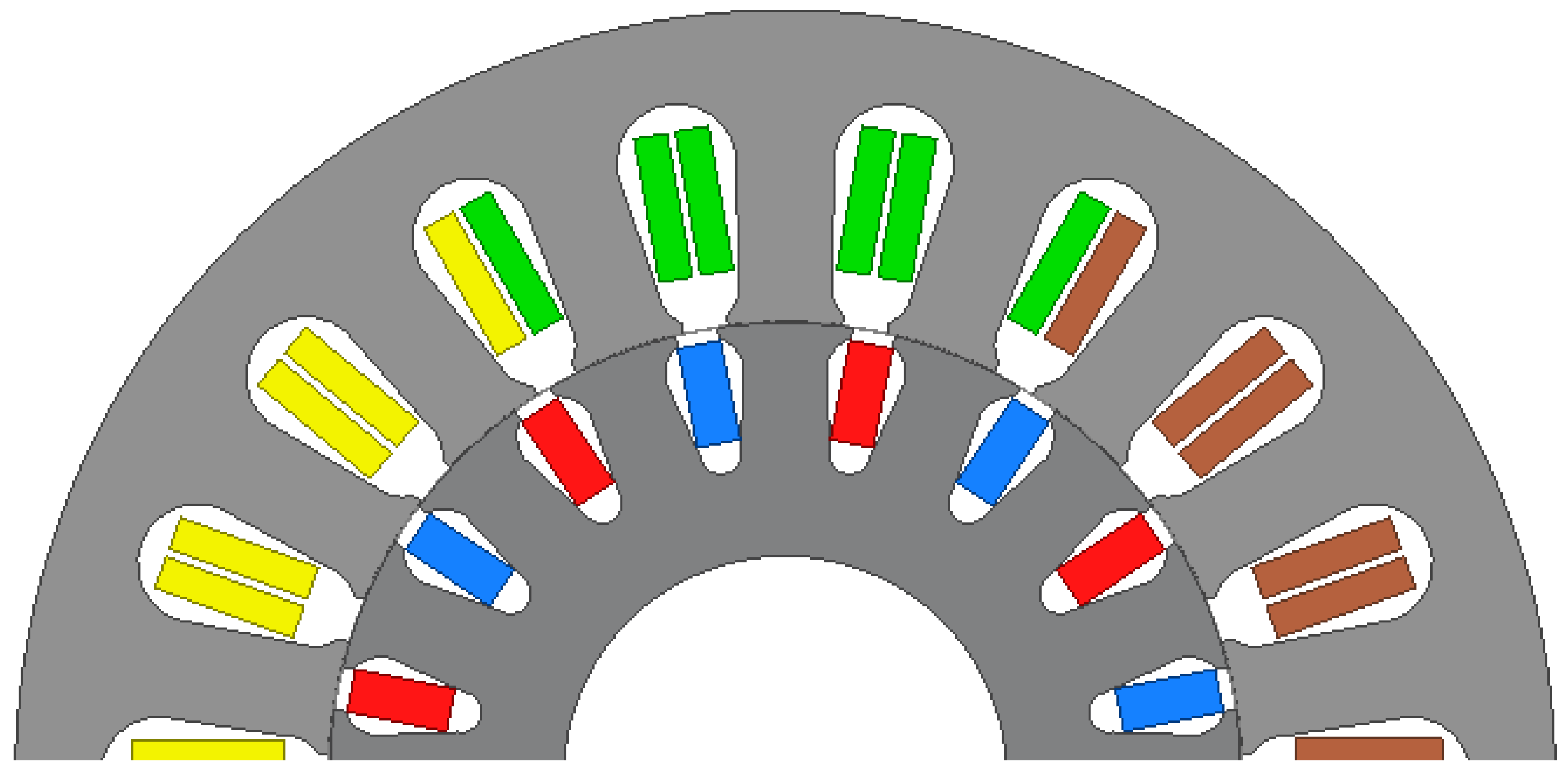
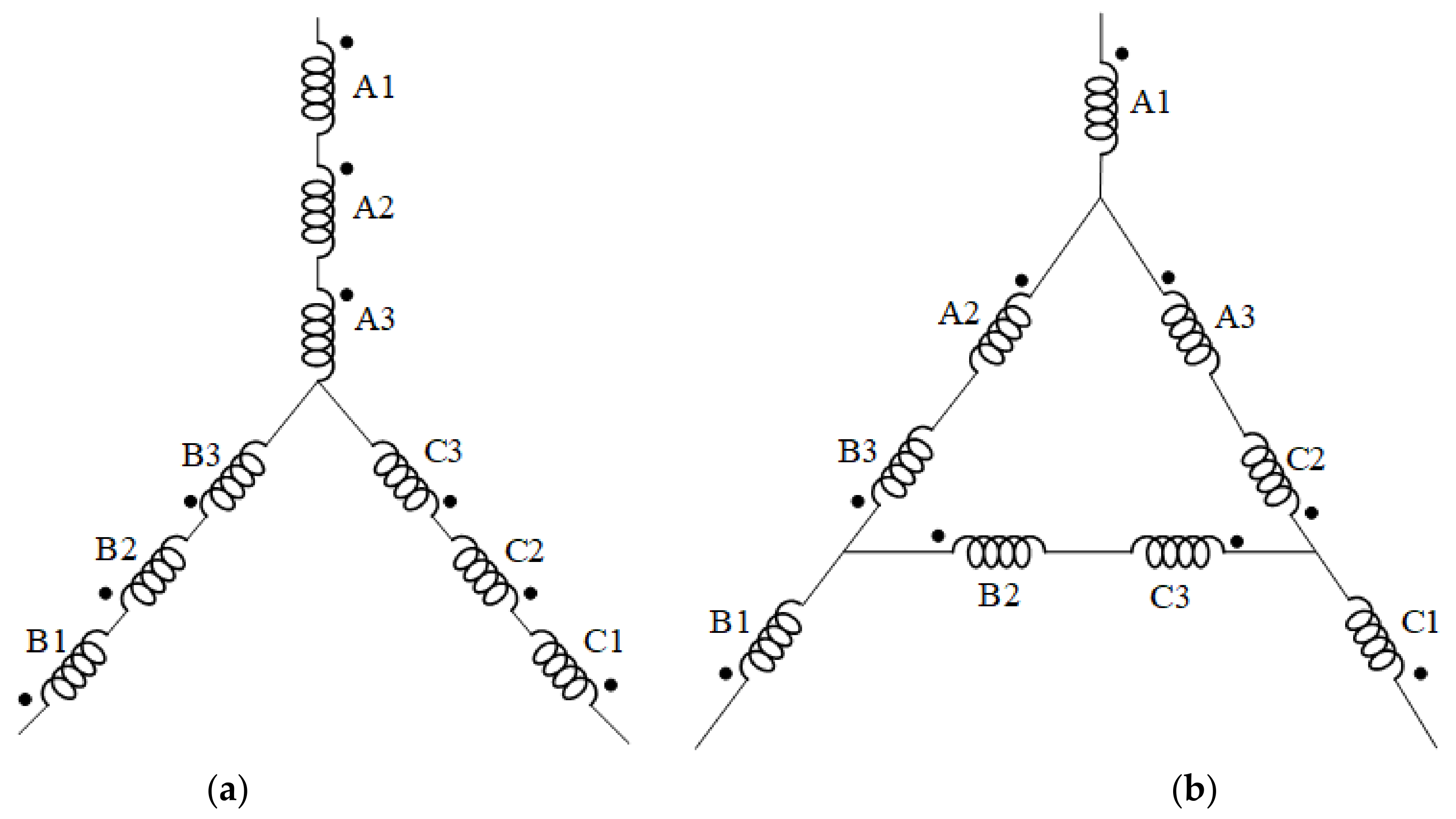
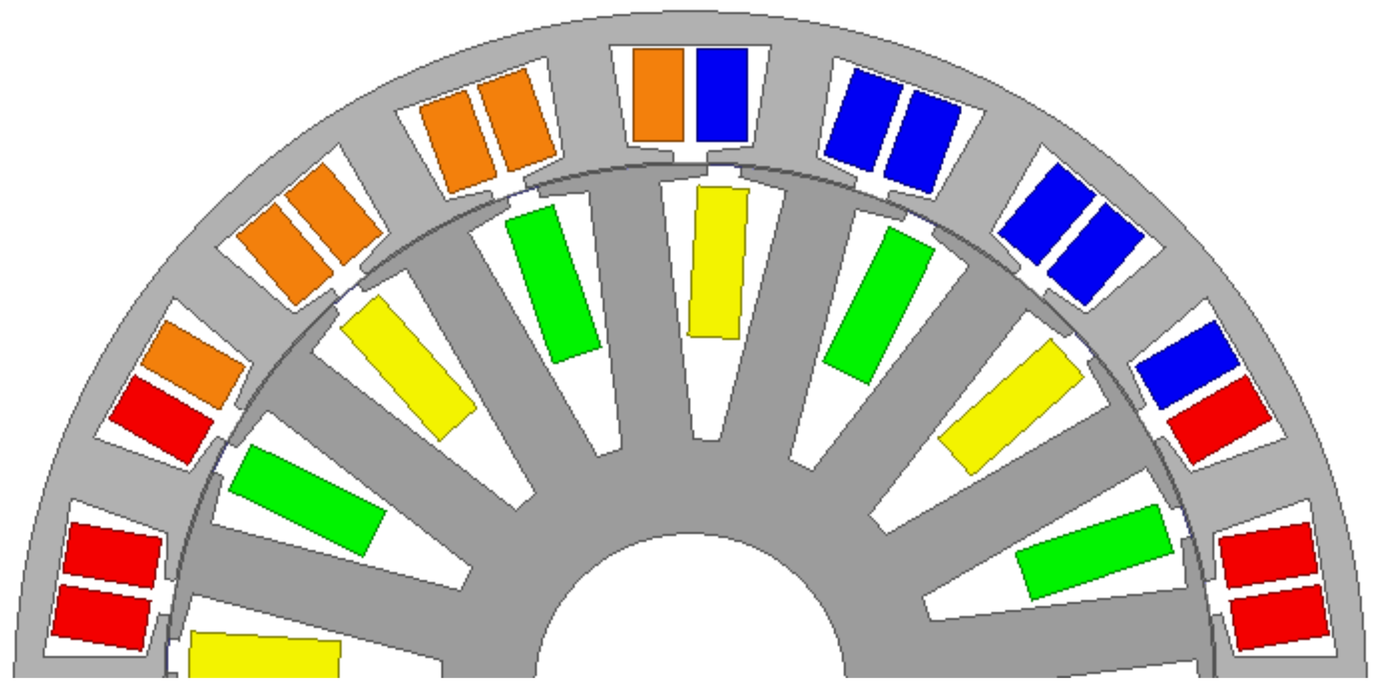
2.1. Proposed 16/18 Phase-Shifted Non-Overlap Winding
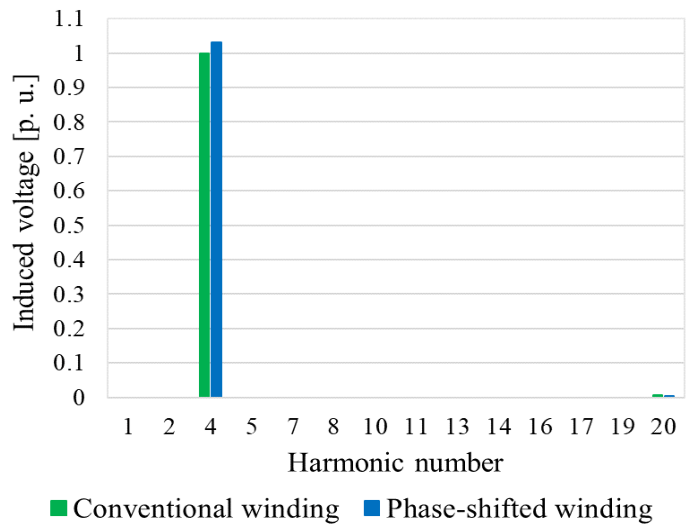
2.2. Harmonic MMF and Distribution Factor
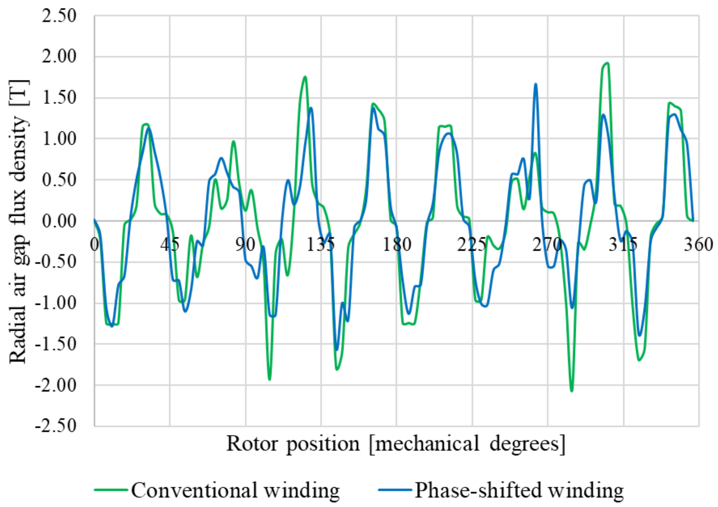
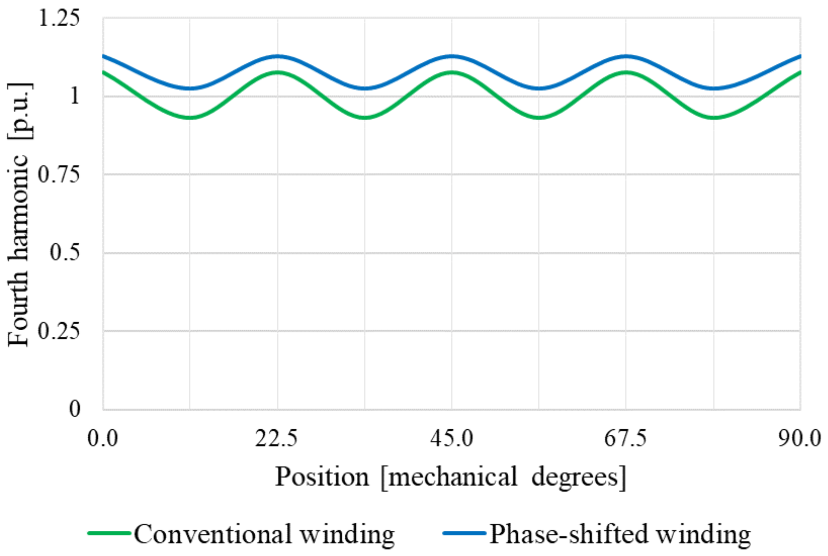
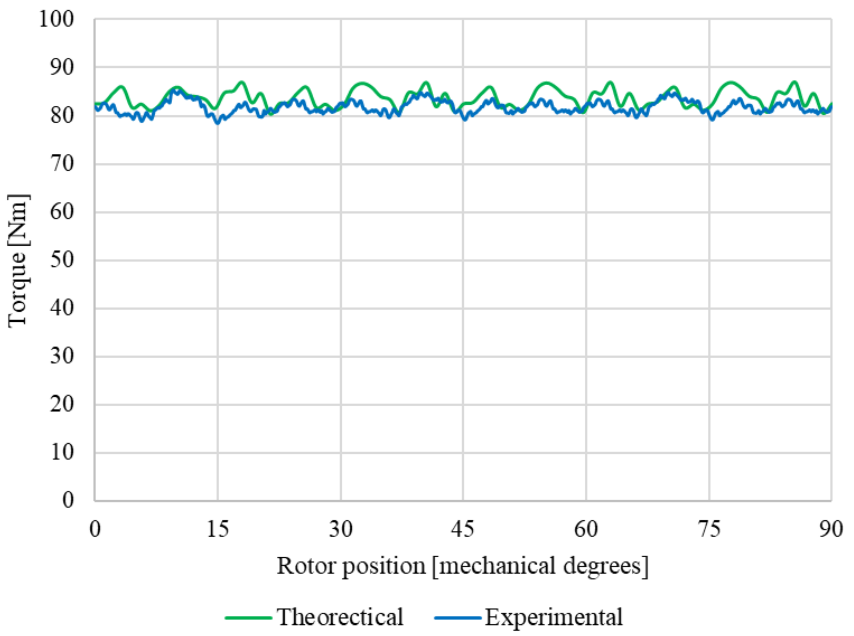
2.3. Flux Density and Torque Harmonic Analysis

| Harmonic Number | Air Gap Flux Density Harmonics in per Unit | ||
|---|---|---|---|
| Conventional 16/18 Winding | Phase-Shifted 16/18 Winding | % Difference | |
| v = 1 | 0.2580 | 0.1532 | −10.48 |
| v = −2 | 0.2971 | 0.1300 | −16.71 |
| v = 4 | 1 | 1.0313 | +3.13 |
| v = −5 | 0.7968 | 0.8218 | +2.49 |
| v = 7 | 0.08262 | 0.0362 | −4.65 |
3. Simulated Performance Results
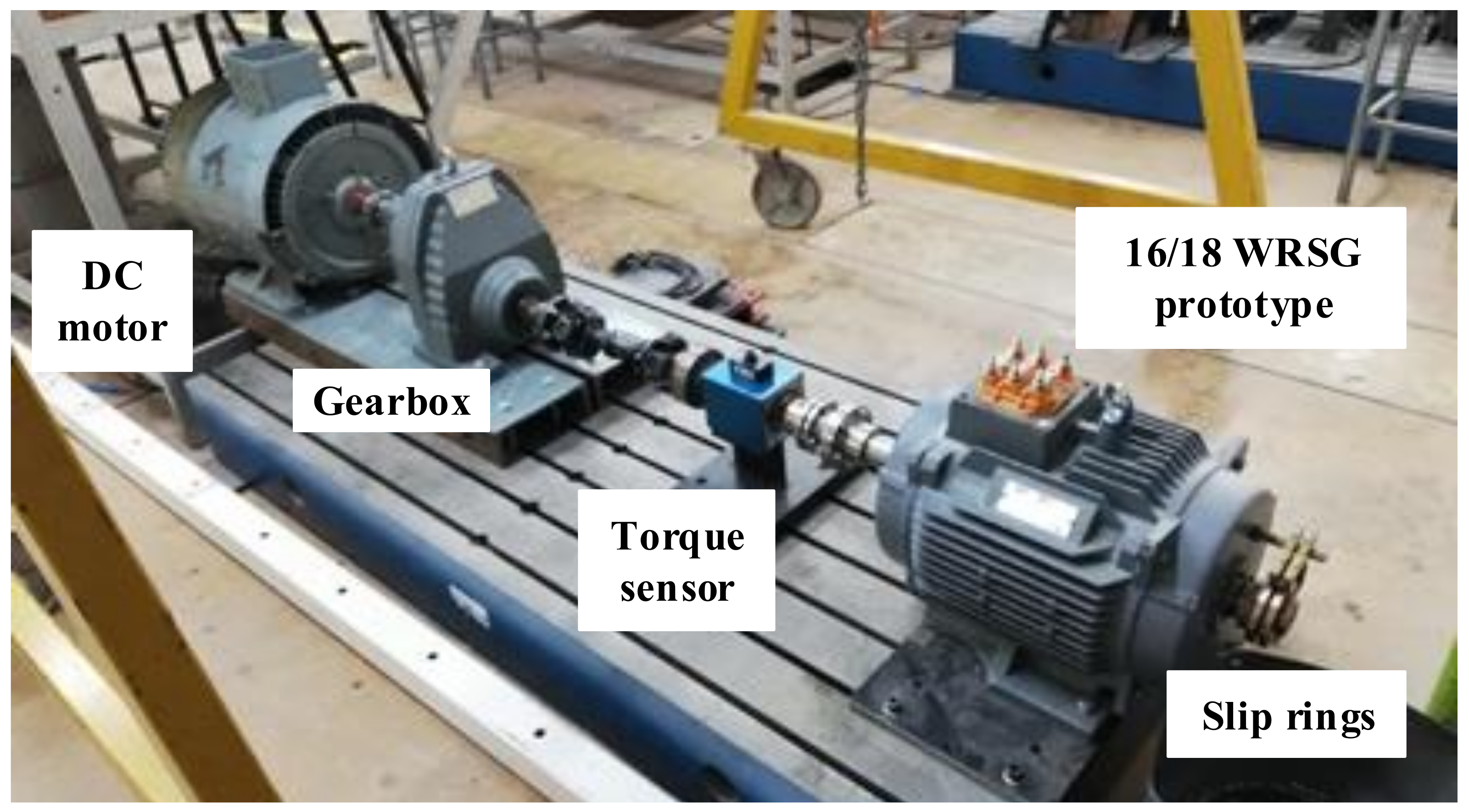
4. Measured Performance Results
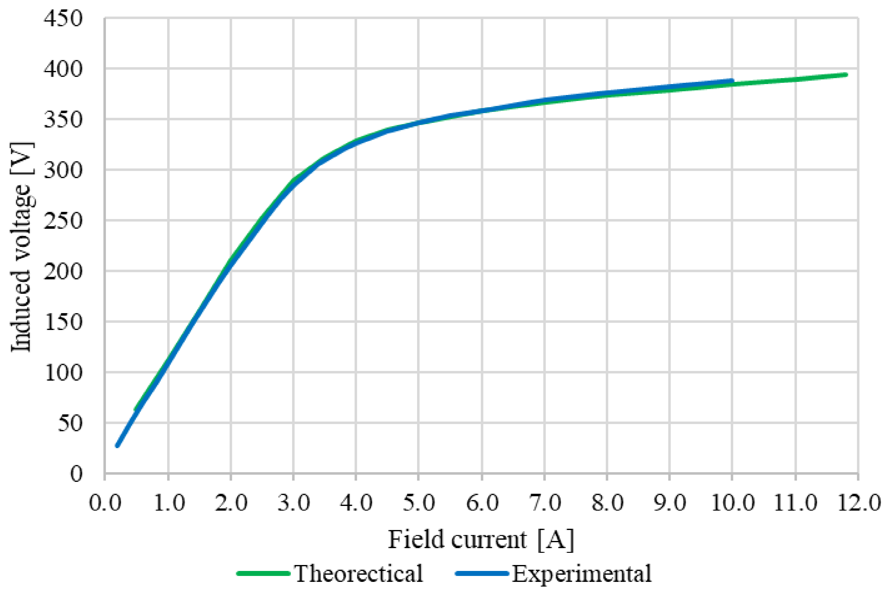
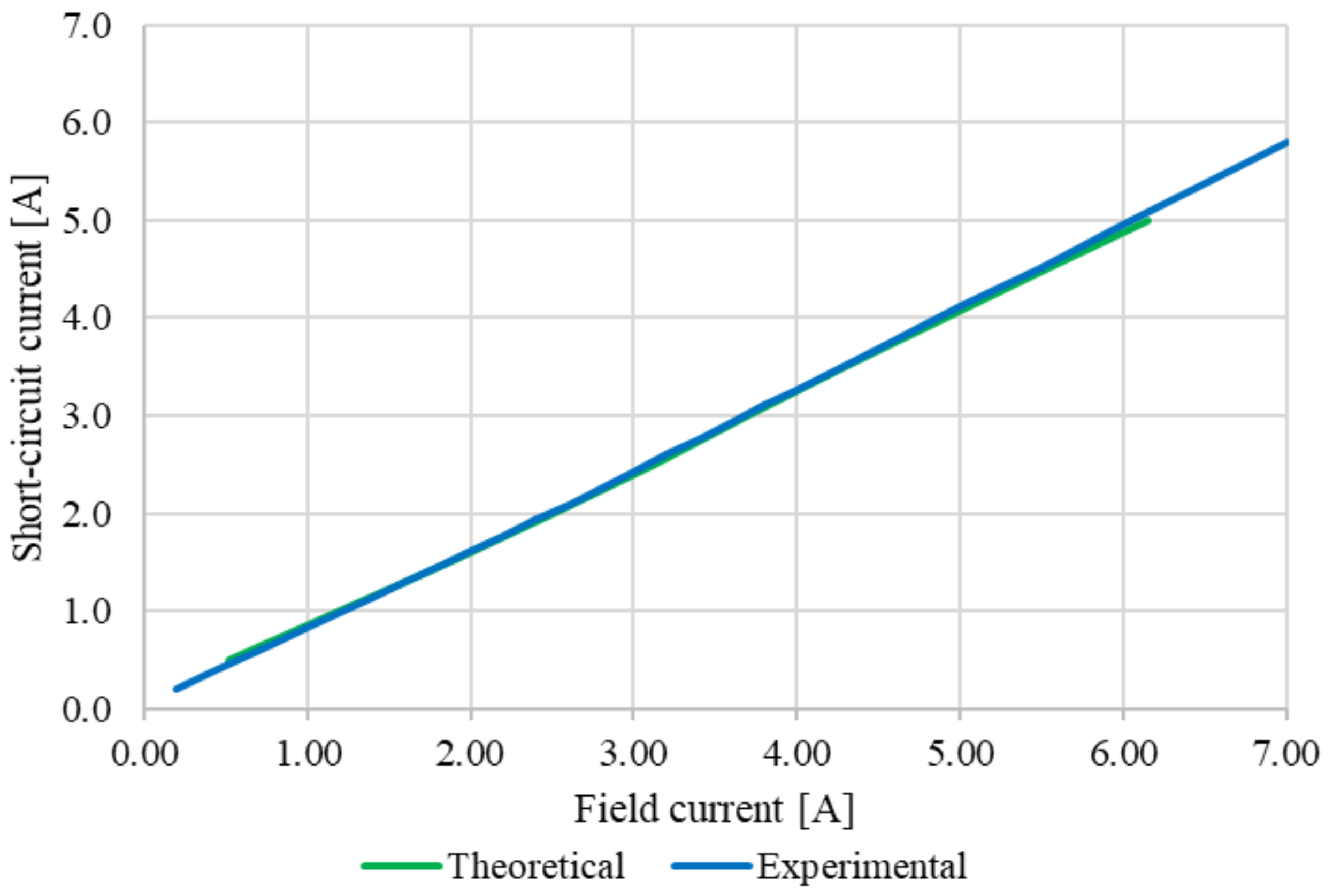
4.1. Machine Parameters from Tests
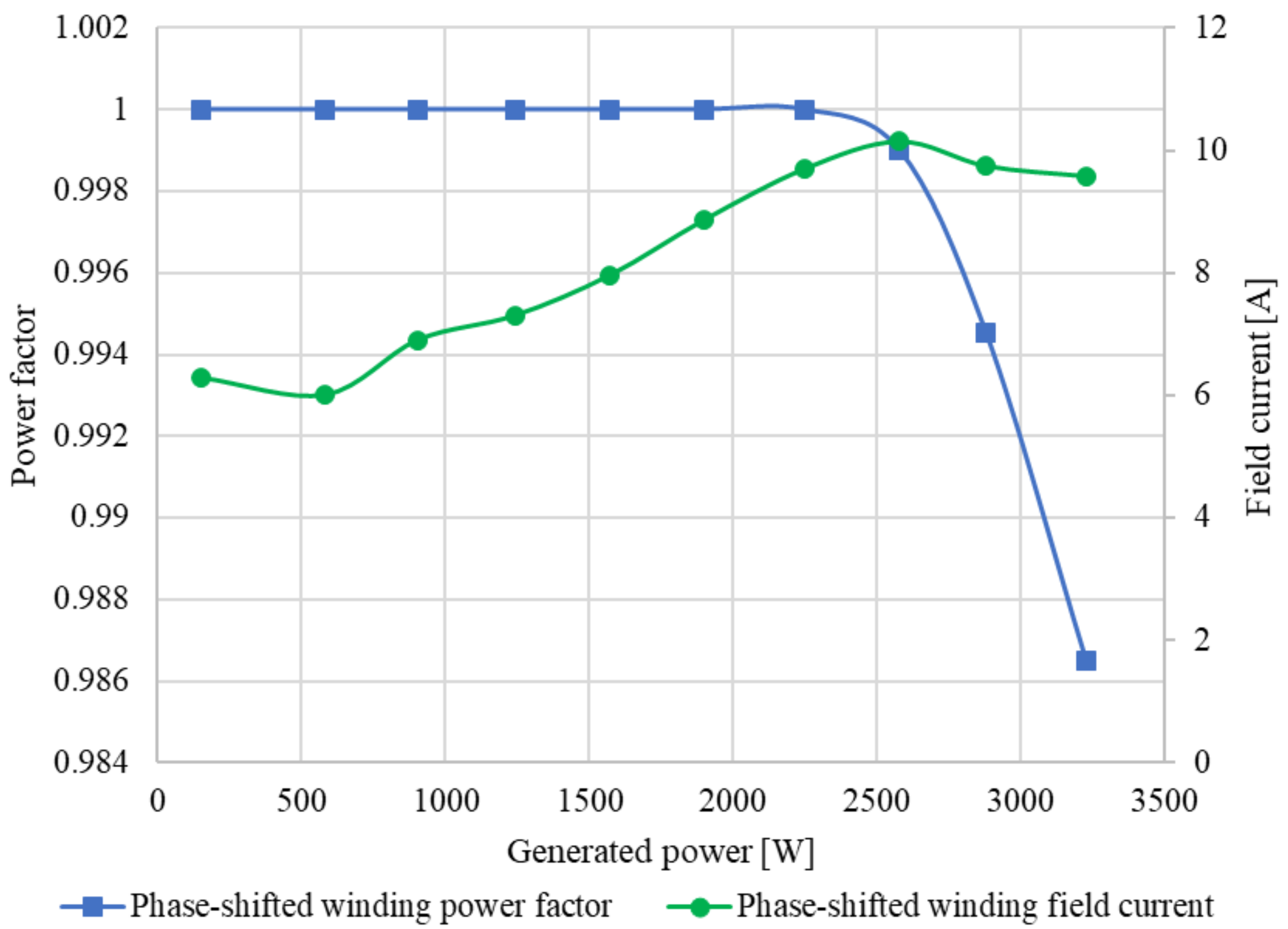
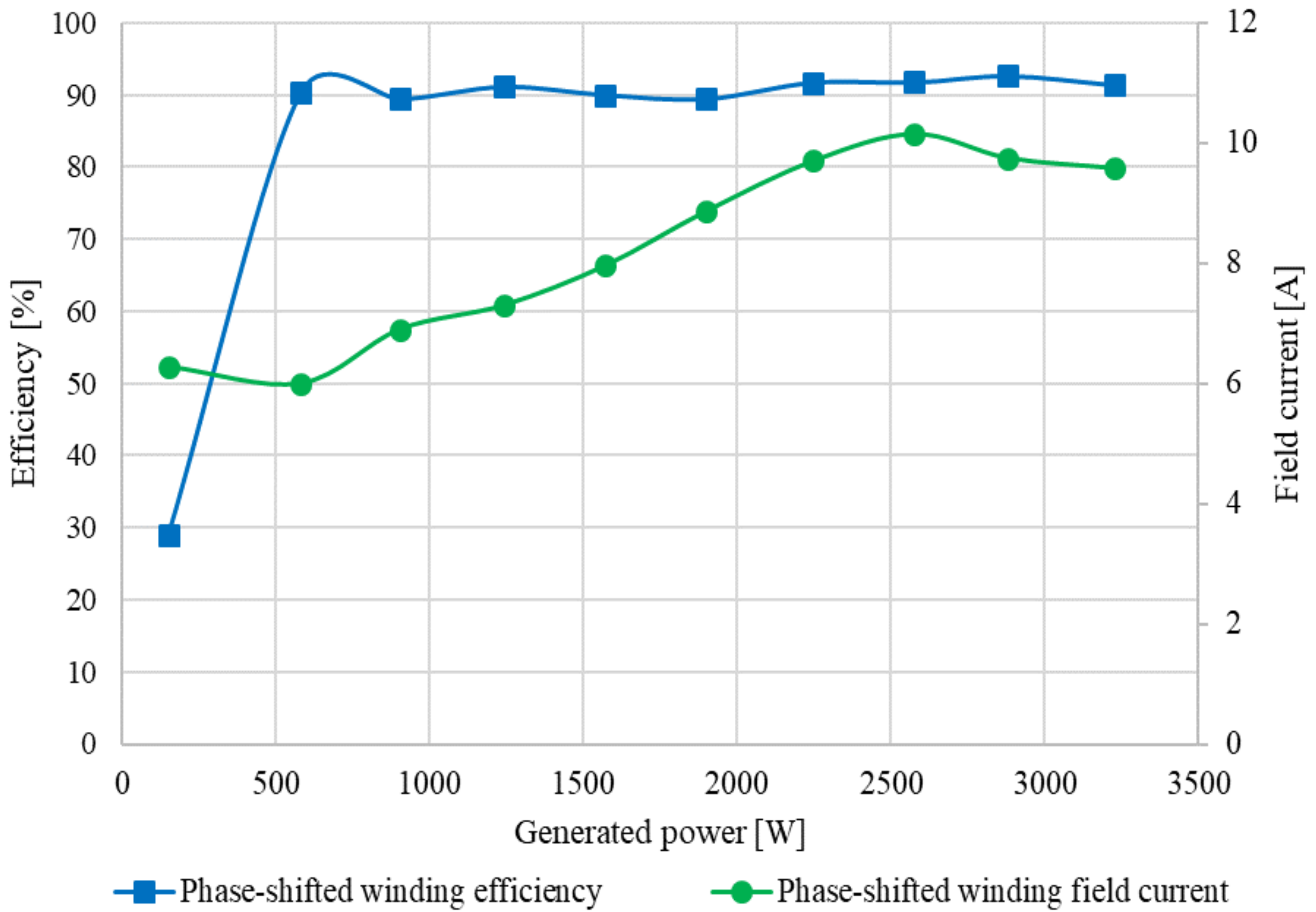
4.2. Grid-Connected Tests
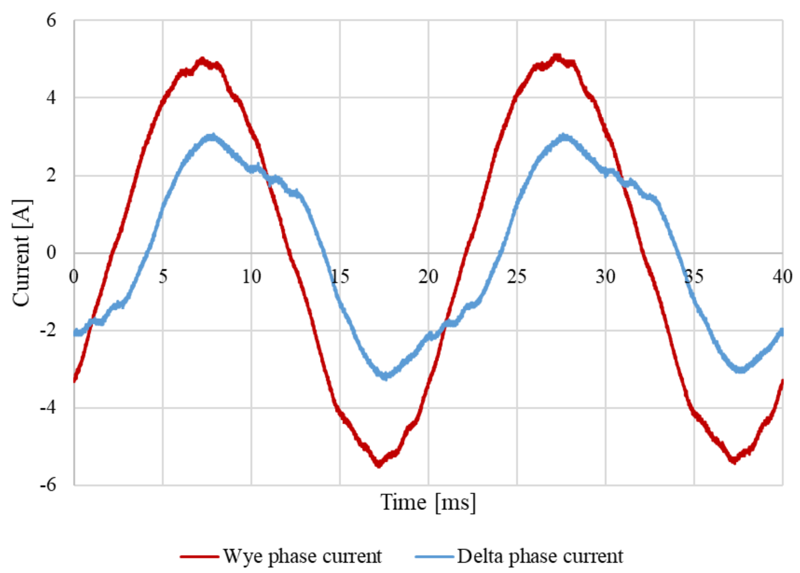
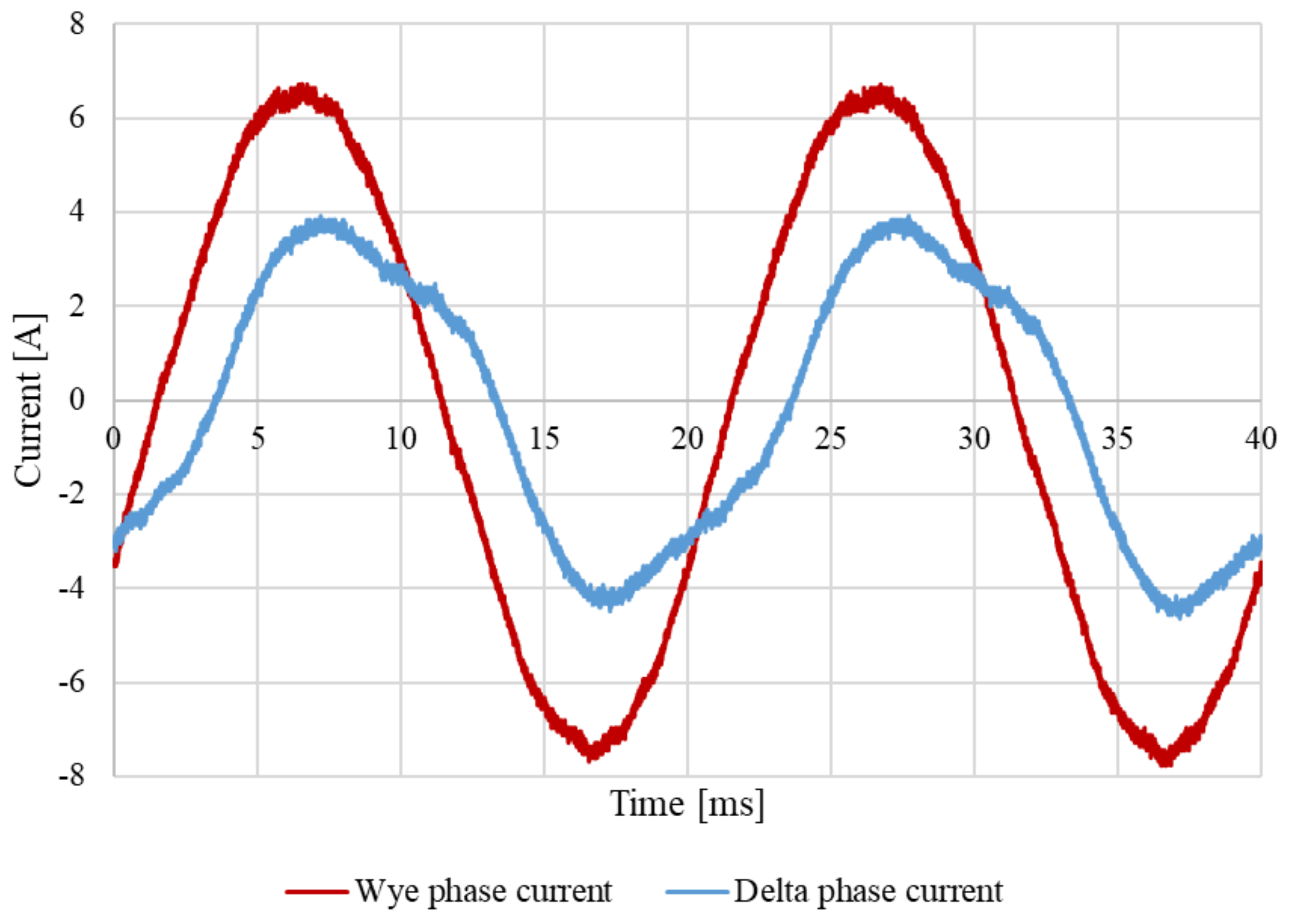
4.3. THD of Wye and Delta Phase Currents
5. Conclusions
Author Contributions
Funding
Institutional Review Board Statement
Informed Consent Statement
Data Availability Statement
Acknowledgments
Conflicts of Interest
References
- REN 21. Renewables 2019 Global Status Report (Paris: REN21 Secretariat). 2019. Available online: www.ren21.net/gsr (accessed on 10 October 2021).
- Dajaku, G.; Spas, S.; Dajaku, X.; Gerling, D. An Improved Fractional Slot Concentrated Winding for Low-Poles Induction Machines. In Proceedings of the 19th International Conference for Electrical Machines, Lausanne, Switzerland, 4–7 September 2016; pp. 116–121. [Google Scholar]
- Alberti, L.; Bianchi, N. Design and tests on a fractional-slot/induction machine. In Proceedings of the IEEE Energy Conversion Congress and Exposition (ECCE), Raleigh, NC, USA, 15–20 September 2012; pp. 166–172. [Google Scholar]
- Heller, F.; Kauders, W. The Görges Polygon (Das Görgessche Durchflutungspolygon). Arch. Elektrotechnik 1925, 29, 599–616. [Google Scholar] [CrossRef]
- Cistelecan, M.V.; Ferreira, F.J.T.E.; Popescu, M. Three phase tooth-concentrated multiple-layer fractional windings with low space harmonic content. In Proceedings of the 2010 IEEE Energy Conversion Congress and Exposition (ECCE), Atlanta, GA, USA, 12–16 September 2010; pp. 1399–1405. [Google Scholar]
- Dotz, B.; Gerling, D. Windings with various numbers of turns per phasor. In Proceedings of the 2017 IEEE International Electric Machines and Drives Conference (IEMDC), Miami, FL, USA, 21–24 May 2017; pp. 1–7. [Google Scholar]
- Dajaku, G.; Xie, W.; Gerling, D. Reduction of low space harmonics for the fractional slot concentrated windings using a novel stator design. IEEE Trans. Magn. 2014, 50, 1–12. [Google Scholar] [CrossRef]
- Dajaku, G.; Gerling, D. A novel 24-slots/10-poles winding topology for electric machines. In Proceedings of the 2011 IEEE International Electric Machines Drives Conference (IEMDC), Niagara Falls, ON, Canada, 15–18 May 2011; pp. 65–70. [Google Scholar]
- Zhu, S.; Shaohong, S.; Cox, T.; Xuand, Z.; Gerada, C. Novel 24-slots 14-poles fractional-slot concentrated winding topology with low-space harmonics for electrical machine. J. Eng. 2019, 17, 3784–3788. [Google Scholar] [CrossRef]
- Bekka, N.; Trichet, D.; Bernard, N.; Zaïm, M. Application of Phase Shifting Technique for Reducing the Magnetomotive Force Space Harmonics of Tooth Concentrated Windings. Electr. Power Compon. Syst. 2016, 44, 1707–1720. [Google Scholar] [CrossRef]
- Garner, K.S.; Kamper, M.J. Reducing MMF harmonics and core loss effect of non-overlap winding wound rotor synchronous machine (WRSM). In Proceedings of the IEEE Energy Conversion Congress and Exposition (ECCE), Cincinnati, OH, USA, 1–5 October 2017; pp. 1850–1856. [Google Scholar]
- Ockhuis, D.K.; Kamper, M.J. Grid Connection Power Converter and Speed Controller for Slip-Synchronous Wind Generators. In Proceedings of the 2019 IEEE Energy Conversion Congress and Exposition (ECCE), Baltimore, MD, USA, 29 September–3 October 2019; pp. 6741–6748. [Google Scholar]
- Kloppers, C.; Garner, K.S.; Kamper, M.J. Design and optimisation of a 16/18 wound rotor wind synchronous generator with non-overlap winding. In Proceedings of the 26th Southern African Universities Power and Engineering Conference, Johannesburg, South Africa, 24–26 January 2018; pp. 1–6. [Google Scholar]


| Specifications | Value |
|---|---|
| Rated terminal power (MW) | 3 |
| Rated torque (kNm) | 76 |
| Rated speed (r/min) | 375 |
| Rated frequency (Hz) | 50 |
| Rated line voltage (V) | 580 |
| Rated phase current (A) | 3000 |
| Rated field current (A) | 200 |
| Stator outer diameter (mm) | 1600 |
| Rotor outer diameter (mm) | 981 |
| Rotor inner diameter (mm) | 460 |
| Stack length (mm) | 1500 |
| Air gap length (mm) | 3 |
| Performance Parameter ↓ | Conventional Winding | Phase-Shifted Winding | Percentage Difference |
|---|---|---|---|
| Terminal power (MW) | 2.96 | 3.05 | +3% |
| Shaft torque (kNm) | 77.14 | 79.45 | +3% |
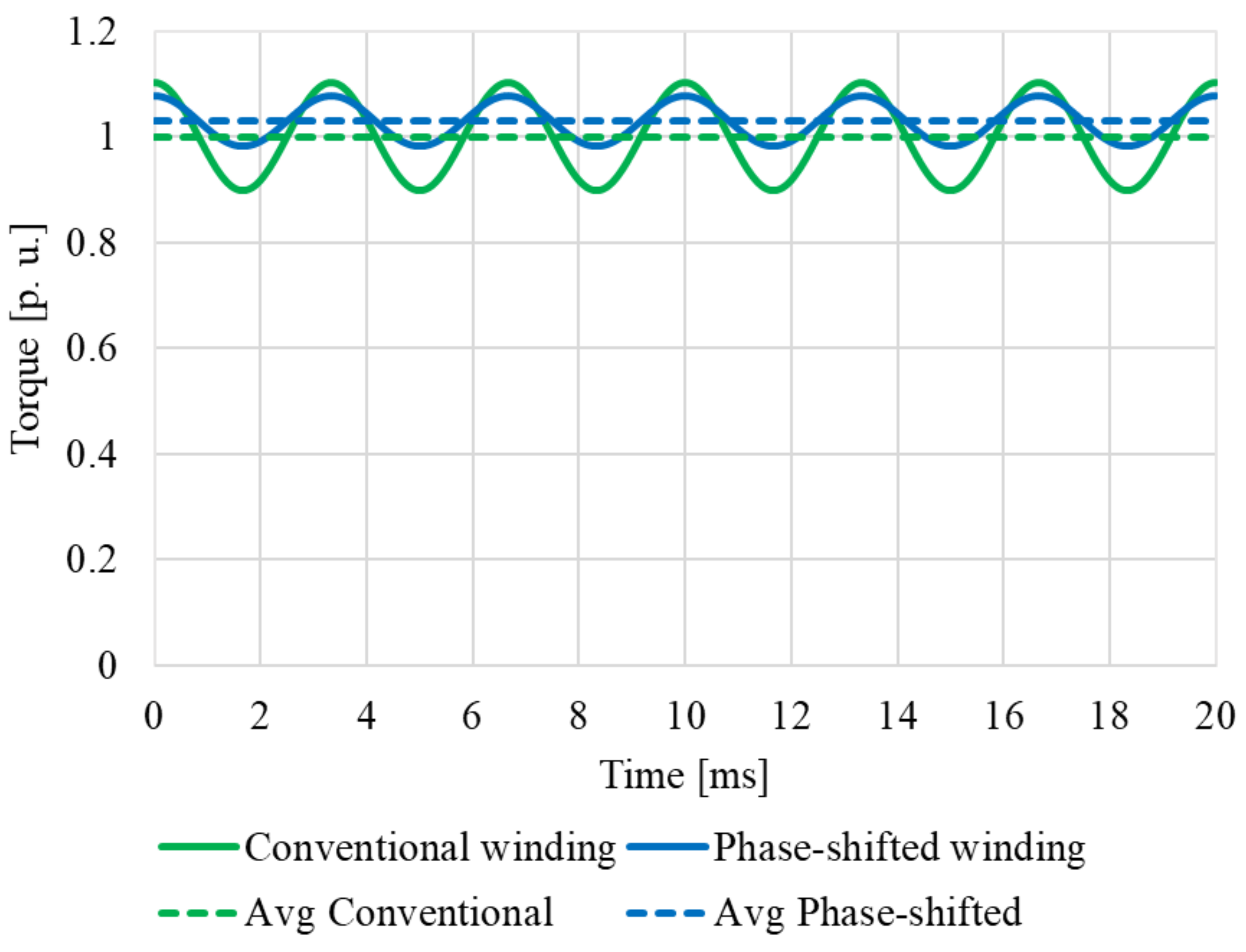
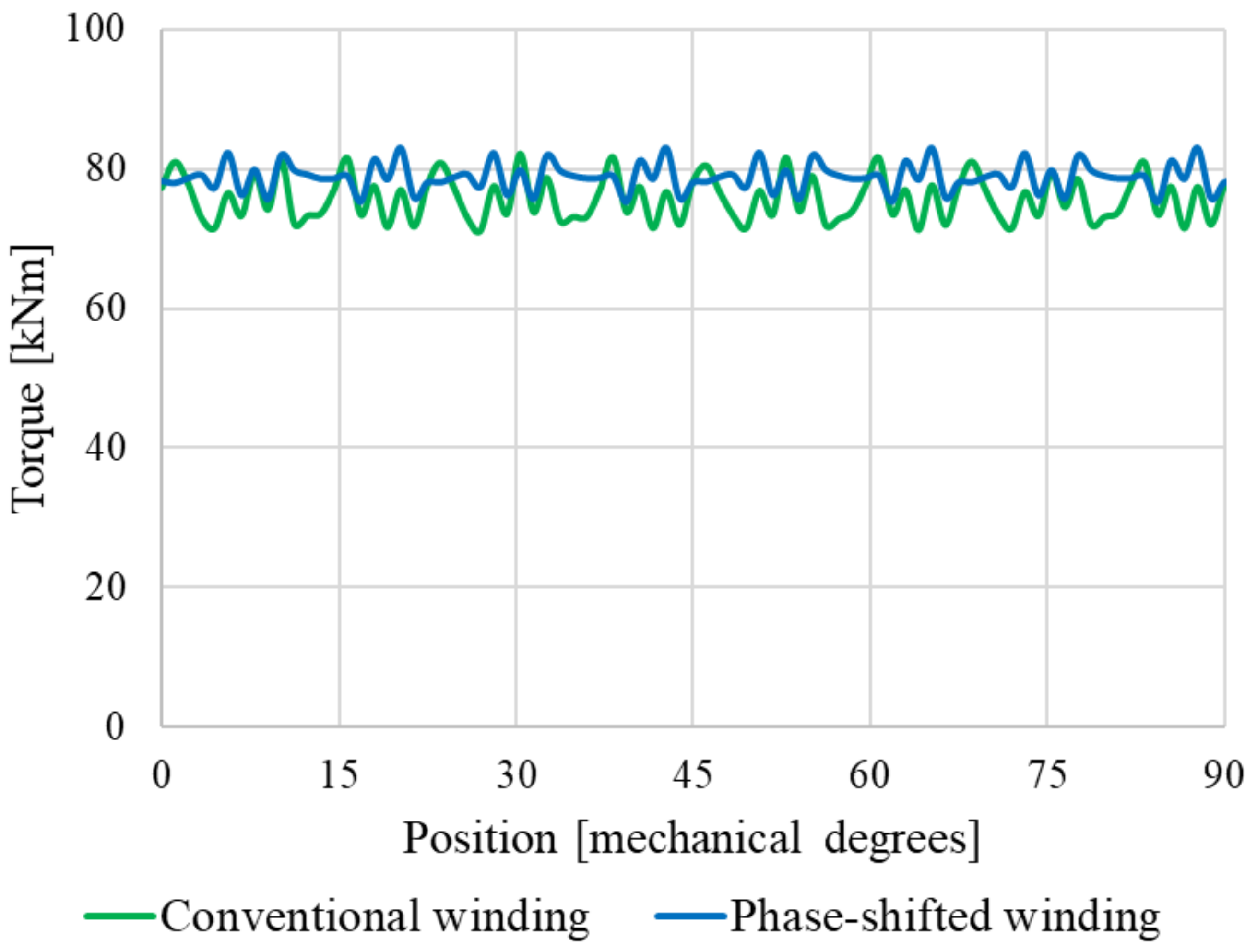
| Torque ripple (%) | 15.32 | 9.53 | −5.79% |
| Rotor core loss (kW) | 8.76 | 8.84 | +0.91% |
| Stator core loss (kW) | 25.58 | 23.19 | −9.3% |
| Copper loss (kW) | 43.08 | 43.08 | −0% |
| Efficiency (%) | 97.40 | 97.57 | +0.17% |
| Specifications | Numerical Value |
|---|---|
| Rated terminal power (kW) | 3 |
| Rated torque (Nm) | 76.5 |
| Rated speed (r/min) | 375 |
| Rated frequency (Hz) | 50 |
| Rated line voltage (V) | 350 |
| Rated phase current (A) | 4.86 |
| Rated field current (A) | 5.00 |
| Number of rotor poles | 16 |
| Number of stator slots | 18 |
| Stator outer diameter (mm) | 260 |
| Rotor outer diameter (mm) | 203.6 |
| Rotor inner diameter (mm) | 60 |
| Stack length (mm) | 125 |
| Air gap thickness (mm) | 0.45 |
| Number turns per coil Y connected | 67 |
| Number turns per coil Δ connected | 116 |
| Parameter | Measured Value |
|---|---|
| Phase resistance, Rs | 4.7 Ω (0.11 per unit) |
| Field resistance, Rf | 8.1 Ω |
| Synchronous reactance, Xs | 42.1 Ω (1.0 per unit) |
| Windage and Friction Losses [W] | Core Losses [W] | Copper Losses [W] |
|---|---|---|
| 19.6 | 62.8 | 94.5 |
| Load Condition | Wye Branch Current THD [%] | Delta Branch Current THD [%] | ||
|---|---|---|---|---|
| Is = 0 A | If = 5 A | – | 0 | 8.9 |
| Is = 3.5 A | If = 10 A | pF = 1 | 5.6 | 7.2 |
| Is = 5 A | If = 9.6 A | pF = 0.987 | 4.5 | 6.1 |
Publisher’s Note: MDPI stays neutral with regard to jurisdictional claims in published maps and institutional affiliations. |
© 2021 by the authors. Licensee MDPI, Basel, Switzerland. This article is an open access article distributed under the terms and conditions of the Creative Commons Attribution (CC BY) license (https://creativecommons.org/licenses/by/4.0/).
Share and Cite
Garner, K.S.; Kamper, M.J.; Loubser, A.T. Performance Evaluation of Harmonic Reduced Non-Overlap Winding Wound Rotor Synchronous Machine. Energies 2021, 14, 7501. https://doi.org/10.3390/en14227501
Garner KS, Kamper MJ, Loubser AT. Performance Evaluation of Harmonic Reduced Non-Overlap Winding Wound Rotor Synchronous Machine. Energies. 2021; 14(22):7501. https://doi.org/10.3390/en14227501
Chicago/Turabian StyleGarner, Karen S., Maarten J. Kamper, and Andrew T. Loubser. 2021. "Performance Evaluation of Harmonic Reduced Non-Overlap Winding Wound Rotor Synchronous Machine" Energies 14, no. 22: 7501. https://doi.org/10.3390/en14227501
APA StyleGarner, K. S., Kamper, M. J., & Loubser, A. T. (2021). Performance Evaluation of Harmonic Reduced Non-Overlap Winding Wound Rotor Synchronous Machine. Energies, 14(22), 7501. https://doi.org/10.3390/en14227501