Article

Assessment and Perspectives of Heat Transfer Fluids for CSP Applications

1
Casaccia Research Centre, Energy Technologies and Renewable Sources Department (TERIN), ENEA, Italian National Agency for New Technologies, Energy and Sustainable Economic Development, 00123 Rome, Italy
2
Casaccia Research Centre, Fusion and Technology for Nuclear Safety and Security Department (FSN), ENEA, Italian National Agency for New Technologies, Energy and Sustainable Economic Development, 00123 Rome, Italy
3
Faenza Research Centre, Territorial and Production Systems Sustainability Department (SSPT), ENEA, Italian National Agency for New Technologies, Energy and Sustainable Economic Development, 48018 Faenza, Italy
*
Author to whom correspondence should be addressed.
Energies 2021, 14(22), 7486; https://doi.org/10.3390/en14227486
Submission received: 19 August 2021 / Revised: 27 October 2021 / Accepted: 29 October 2021 / Published: 9 November 2021
(This article belongs to the Special Issue Solar Thermodynamic Materials Overview)

Abstract

:
Different fluid compositions have been considered as heat transfer fluids (HTF) for concentrating solar power (CSP) applications. In linear focusing CSP systems synthetic oils are prevalently employed; more recently, the use of molten salt mixtures in linear focusing CSP systems has been proposed too. This paper presents a comparative assessment of thermal oils and five four nitrate/nitrite mixtures, among the ones mostly employed or proposed so far for CSP applications. The typical medium-size CSP plant (50 MWe) operating with synthetic oil as HTF and the “solar salt” as TES was considered as a benchmark. In the first part of the paper, physical properties and operation ranges of different HTFs are reviewed; corrosion and environmental issues are highlighted too. Besides an extensive review of HTFs based on data available from the open literature, the authors report their own obtained experimental data needed to thoroughly compare different solutions. In the second part of the paper, the impact of the different HTF options on the design and operation of CSP plants are analyzed from techno-economic perspectives.

1. Introduction

The current global energy transition from a fossil-based to a sustainable economy entails the assessment, use and combination of different energy sources and technologies. This pathway involves the short-term exploitation of mature and cost-competitive technologies; in the meantime, fast technology improvements are needed to bring other technologies to competitive readiness and costs. This is the case of Concentrating Solar Power (CSP): as power grid operators suffer by the steady increase of vRES (variable Renewable Energy Sources) driving grid to instability, the last decades showed a steady increase of the interest on CSP for utility-scale dispatchable power generation.
First utility-scale CSP experiences started in the USA in the 1980s. However, it is since 2008 that worldwide installed CSP capacity started to significantly grow, from <0.5 GWe to >5 GWe in less than 10 years [1]. This growth was mainly driven by the extensive diffusion of CSP in Spain and, after 2012, in the USA. More recently big projects are contributing to the further growth of CSP in other “sun belt” countries such as Morocco, South Africa, Emirates, China, Chile and India.
Most CSP plants installed so far are based on Parabolic Trough (PT) collectors using Thermal Oil (TO) as Heat Transfer Fluid (HTF) up to about 393 °C; indirect Thermal Energy Storage (TES) is used with a molten salt mixture—namely the “solar salt”, a mixture of NaNO3 (60%wt.) and KNO3 (40%wt.)—as heat storage medium. This PT-TO technology is highly modular, mature, reliable and cost-effective, enabling to obtain relevant capacity factors. However, power production costs remain an issue [2] and some improvements can be obtained with the changeover of the thermal fluid, with potential improvements on plant design, costs and performance, as discussed in the following sections.
Figure 1 shows a general scheme of a CSP plant with linear concentrators. This common layout makes use of parabolic trough collectors arranged in loops to heat up a thermal oil, typically a diphenyl oxide (DPO, e.g., Therminol-VP) up to about 390–400 °C. The thermal oil transfers the captured solar heat to the solar salt in an oil/molten salt heat exchanger (HEX); here, the solar salt is used as heat storage medium in a 2-tanks TES arrangement in the range from 290 °C (cold molten salt tank temperature) to 380 °C (hot molten salt tank temperature). The common “standard” size of CSP plants using parabolic troughs with thermal oil (PT-TO) is 50 MWe, although larger and smaller power stations (from 5 MWe to 200 MWe or more) have been built worldwide [2,3,4,5].
Some advanced large-scale stations use a different CSP technology based on a Solar Tower with Molten Salt (ST-MS), where the solar salt is also used as HTF in the solar receiver up to about 565 °C; in ST-MS systems a “direct” TES is applied, i.e., the same HTF is also used as heat storage medium.
Recent studies show that the use of solar salt as HTF in linear concentrators can combine the benefits of the modularity, maturity and low-cost of the linear CSP technology with several benefits introduced by the use of the molten salt as HTF [3,6,7,8,9].
Figure 2 shows a different CSP plant layout where the solar salt is used also as HTF in the solar field. In this case, thanks to the higher stability of the HTF, higher temperatures can be obtained, while the use of a “direct” TES system avoids the installation of an intermediate oil/MS heat exchanger.
Experimental test loops have been developed to validate concepts and components of the PT-MS technology using solar salt HTF [10,11,12]. In this contest, a 1 MWe PT-MS demo plant has been built in a desert area in Borg El Arab, Egypt, in the framework of the European project MATS—Multipurpose Applications by Thermodynamic Solar [13]. Another test loop based on a ternary molten salt mixture (KNO3, NaNO2 and NaNO3, also called HITEC®) in linear Fresnel collectors was built in Spain in 2013 [14].
Similar layout can be applied also when a different molten salt mixture is used as HTF in linear concentrators, depending on the heat load and end-users’ requirements, for example for the supply of heat for industrial processes [15].
It is possible to estimate the operating and management costs as about 2% of the initial investment (see Sau et al. and Delise et al. [16,17]). Other aspects are difficult to be quantified, especially regarding how the handling of operating problems can be related to the properties of the used thermal fluids. As a rule, the employment of oils or low melting HTF mixtures facilitate filling and emptying operations, along with start-up procedures. Thermal oils are, in principle, more handy, but they pose severe problems concerning safety and dispersion in the environment (see Delise et al. [16]). All in all, as far as management issues are concerned, low melting mixtures are preferable as heat transfer and storage fluids.
This paper presents a comparative assessment between thermal oils (synthetic and mineral oils) and four molten nitrate/nitrite mixtures, considering the ones mostly employed or proposed so far for CSP applications. The methodology can be extended to other formulations such as more complex ternary or quaternary molten salt mixtures or silicone oils; however, the majority of new formulations still lack basic data (e.g., physical/chemical properties, corrosion and costs) to be thoroughly included in the comparison. It is also worth mentioning that nanoparticles added fluids have been recently proposed for the applications concerned, obtaining significant increases in both specific heat and thermal conductivity, due to the presence of small scale effects [18,19,20]. Anyway, these pioneering HTFs are not considered in this work, given the lack of information about their cost and stability.
In the first part of the paper, physical properties and operation ranges are reviewed, along with corrosion, safety and environmental issues. In the second part of the paper, the impact of the different HTF options on the design and operation of CSP plants is analyzed from techno-economic perspectives.

2. Material Properties

2.1. Physical Properties and Operation Range

2.1.1. Thermal Oils

Thermal oils can be classified into three main groups according to their origin and chemical composition: synthetic oils, mineral oils and “others”. The last category includes promising thermal oils of different kind (i.e., non-hydrocarbon-based oils), such as silicon-based oils; this type of HTF is not addressed in this paper due to uncertainties on physical properties, costs and environment impact.
In the case of synthetic oils, the main components are obtained via chemical synthesis processes or using methods different from conventional refining, being these materials generally based on aromatic-like compounds. As representative examples of this category, three widely commercialized synthetic oils HTFs are considered in this paper [1], namely:
  • Therminol 66, mainly consisting of terphenyl and partially hydrogenated therphenyls;
  • Therminol SP (or Dowtherm HT) composed by benzene alkyl derivates;
  • Therminol VP-1, an eutectic mixture of diphenyl oxide (DPO) and biphenyl.
Differently, mineral oils are derived as a by-product of refining processes. Therminol XP (White Mineral Oil) is considered in this work.
Table 1 reports the thermo-physical properties of the above mentioned four thermal oils, along with the operating temperature ranges recommended by manufacturers.

2.1.2. Molten Salts

As introduced in the previous section, the so-called “solar salt” is today the most used nitrate mixture as heat transfer fluid and storage material for CSP applications [25]. Actually, this fluid shows good thermo-physical properties, high thermal stability (up to 600 °C [17]), low cost and no toxicity. One significant shortcoming of the solar salt is related to its freezing point around 238 °C [25]. This feature leads to the necessity of applying specific anti-freezing systems along the HTF loop.
With the aim to mitigate the drawback of the relatively high freezing temperature of the solar salt, molten salt mixtures with lower melting temperatures (<150 °C) were proposed in the scientific literature [25]. Table 2 summarizes the thermo-physical properties of the molten salt mixtures here considered; the “solar salt” properties can be compared with those of three alternative molten salt mixtures.
The molten salt mixture commercially known as Hitec® (Table 2) is characterized by the presence of sodium nitrite and shows a relatively low freezing point together with good features concerning specific heat, density and viscosity. However, this material is toxic and less thermally stable than the solar salt under air [25,26].
Another interesting alternative is represented by the molten salt mixture commercially known as Hitec XL®, composed by calcium, potassium and sodium nitrates [16]. However, as shown in Table 2, the viscosity of the Hitec XL® mixture is much higher than the one of the solar salt, especially at temperatures approaching the freezing point, while its thermal stability in presence of air is similar to the one of Hitec® [25].
Finally, the addition of lithium nitrate significantly decreases the freezing point of the molten salt mixture while, at the same time, similar thermo-physical properties and stability of the solar salt can be obtained [25]. This finding makes the Li-containing mixture rather interesting. However, cost and availability of lithium can represent a bottleneck for its utilization in CSP plants with large-scale TES capacity. Among several proposed compositions, the most studied mixture with Na/K/Li nitrates [25] is the one reported in Table 2.
Table 2. Thermo-physical properties of the “solar salt”, Hitec®, Hitec XL® and lithium containing ternary molten salt mixtures.
Solar Salt
Chemical composition (%wt)NaNO3/KNO3 (60/40)
Density kg m 3 vs. temperature ° C ρ = 2090 0.63 · T [27]
Dynamic Viscosity [cP] vs. temperature ° C μ = 71,645 · T 1.763 (*)
Thermal conductivity [ W ° C m ] vs. temperature ° C k = 0.3804 + 3.452 · 10 4 · T [28]
Heat capacity [ kJ ° C kg ] vs. temperature ° C cp = 1.5404 + 3.0924 · 10 5 · T (*)
Thermal stability (max operation temperature)600 °C[16]
Liquidus temperature (initial solidification point)238 °C[29,30]
Hitec® (Na/K nitrate/nitrite)
Chemical composition (%wt)NaNO3/KNO3/NaNO2 (7/53/40)
Density kg m 3 vs. temperature ° C ρ = 0.9 · T + 2269.4 [31]
Dynamic Viscosity [cP] vs. temperature ° C μ = 146,452 · T 1.903 (*)
Thermal conductivity [ W ° C m ] vs. temperature ° C k = 0.5843 0.0006 · T [26]
Heat capacity [ kJ ° C kg ] vs. temperature ° C cp = 1.55 0.0001 · T [26]
Thermal stability (max operation temperature)450 under air; 530 °C under inert gas[26]
Liquidus temperature (initial solidification point)141 °C [32]
Hitec XL® (Na/K/Ca nitrate)
Chemical composition (%wt)NaNO3/KNO3/Ca(NO3)2 (15/43/42)
Density kg m 3 vs. temperature ° C ρ = 2240 0.827 · T [33]
Dynamic Viscosity [cP] vs. temperature ° C μ = 509,611 · T 2.072 (*)
Thermal conductivity [ W ° C m ]~0.519 (constant in the operative range)[31]
Heat capacity [ kJ ° C kg ] vs. temperature ° C cp = 1.542 0.000322 · T (*)
Thermal stability (max operation temperature)≤425 °C[34]
Liquidus temperature (initial solidification point)~125 °C[35]
Na/K/Li nitrate
Chemical composition (%wt)NaNO3/KNO3/LiNO3 (18/45/37)
Density kg m 3 vs. temperature ° C ρ = 2051 0.6639 · T [31]
Dynamic Viscosity [cP] vs. temperature ° C μ = 58,725 · T 1.69 (*)
Thermal conductivity [ W ° C m ] k = 0.0005 · T + 0.4 [31]
Heat capacity [ kJ ° C kg ] vs. temperature ° C cp = 1.5395 + 0.0003 · T (*)
Thermal stability (max operation temperature)600 °C[17]
Liquidus temperature (initial solidification point)120 °C[36]
* data obtained by ENEA in the framework of the “Concentrating Solar Power” project under the “Electric System Research” Programme 2019–2021.

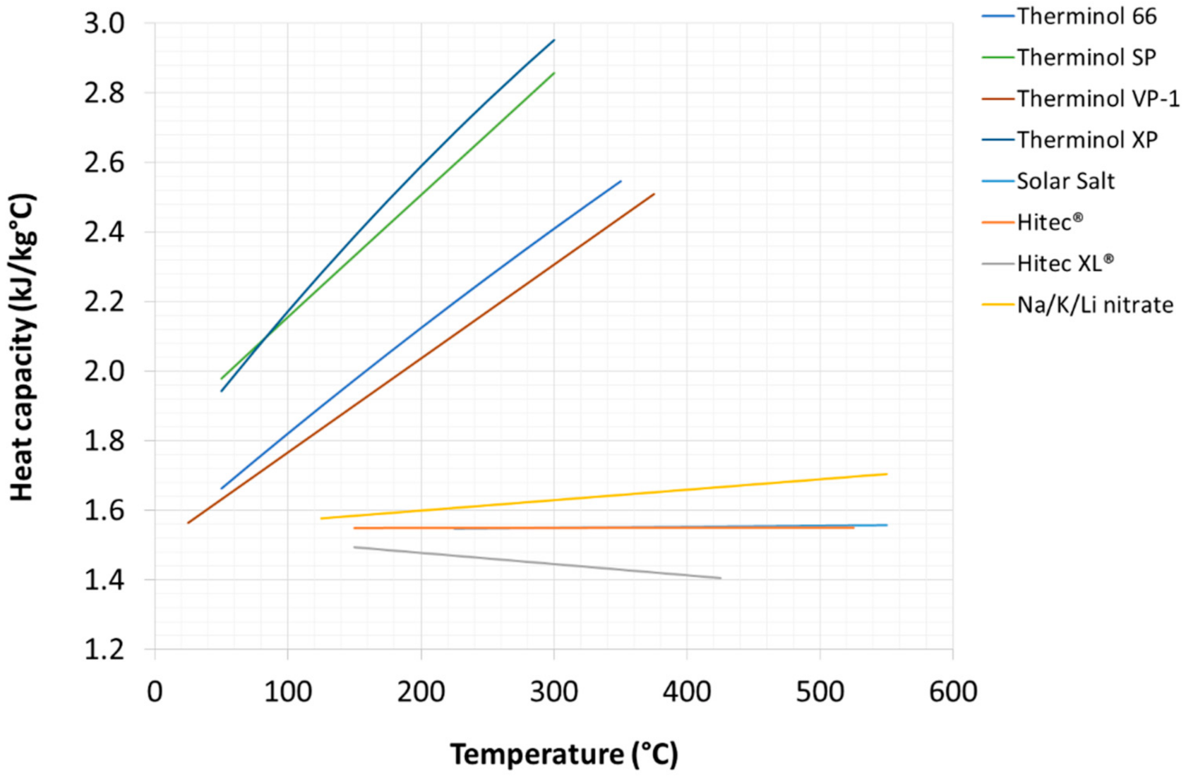
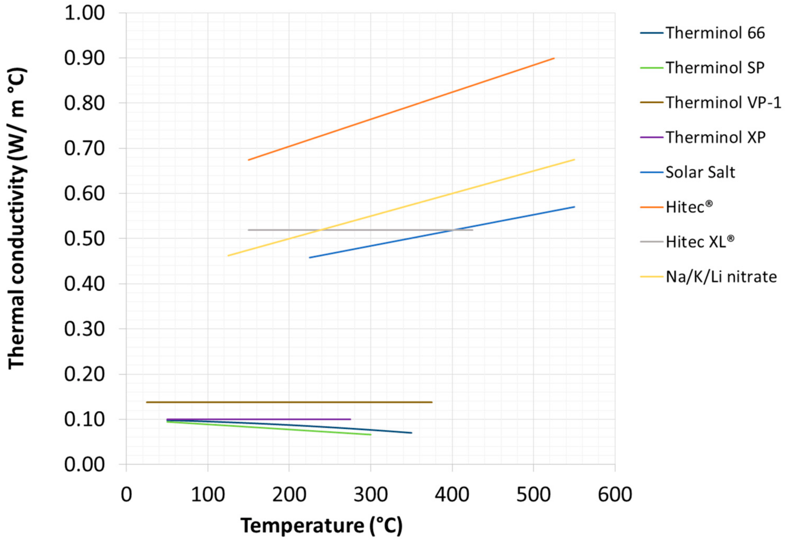
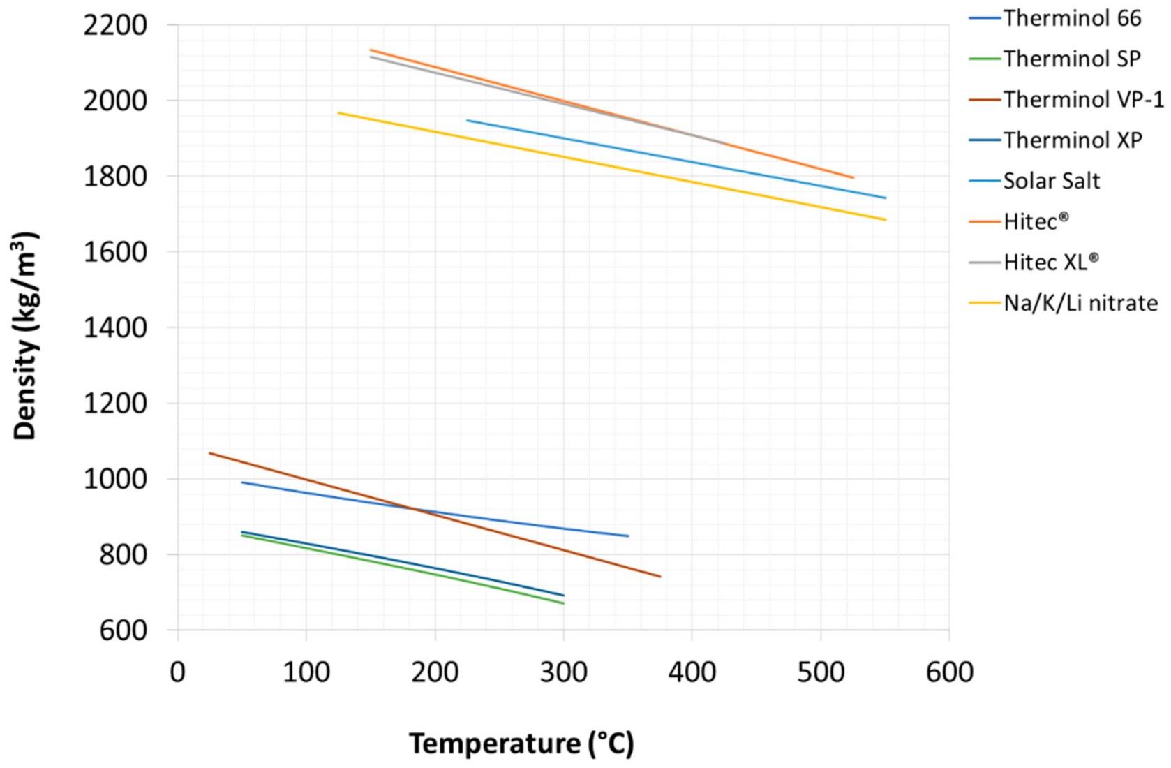
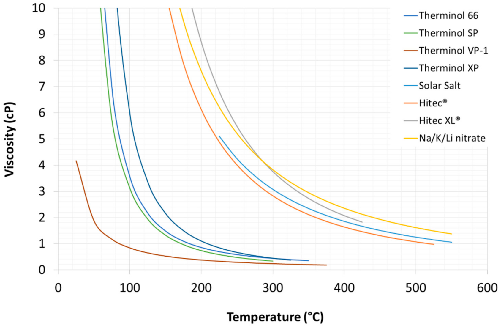
2.1.3. Comparison between HTFs’ Thermo-Physical Properties

Figure 3, Figure 4, Figure 5 and Figure 6 show a comparison between the thermo-physical properties of the HTFs considered in this work within their respective operating temperature ranges. Clearly, molten salts are characterized by higher densities, while thermal oils show higher specific heat, lower viscosity and lower thermal conductivity.
Thermal oils are used both as heat transfer fluids and as storage materials only in CSP plant with TES based on solid fillers [37]; therefore, the volumetric energy density of thermal oil is less important than for molten nitrates/nitrites, which are also employed as sensible heat storage medium [25]. Figure 7 shows compares the four molten salt formulations, considering average values for density and heat capacity in their respective working temperature ranges.

2.2. Material Corrosion Issues

Besides thermo-physical properties, a comprehensive assessment of different HTF solutions includes the assessment of corrosion issues towards steel components of the CSP plant such as pipes, valves, tanks and welding joints. Specifically, compared to thermal oils, molten nitrates show some drawbacks linked to the degradation of nitrates into nitrites, with possible oxygen generation, when the fluid is heated above 295 °C [38].
Studies carried out so far on steel corrosion with mixtures of molten nitrates are not adequately systematic. Furthermore, these tests sometime provide contradictory results; there are no validated/shared methods for carrying out the corrosion tests. Additionally, test conditions are not always representative of the real environment in CSP plants: for example, TES tanks in CSP plants are not perfectly airtight and the presence of air in the gas above the liquid salt can cause degradation of a nitrite-containing molten salt like the Hitec® mixture.
Table 3 summarizes the most significant results published in the scientific literature regarding the corrosion of different types of steel in contact with the most used molten nitrate salt binary and ternary mixtures.
The most important parameters to investigate the corrosion phenomena are:
  • type and purity of the salt mixture. In particular, the chloride content is considered critical if >0.1%wt., although in literature there are data up to 1% [44];
  • corrosion test conditions: static or dynamic immersion, thermal cycling, temperature, nitrogen or air atmosphere, duration;
  • oxides produced by corrosion;
  • corrosion rate (CR), expressed as thickness change per year, according to the formula:
CR = Δ M · 8760 ρ   S · Δ t
where ΔM is difference between the final and the initial mass of the specimen; 8760 is the number of hours per year; ρ is the density of the steel sample; S is the surface area exposed to corrosion; Δt is the duration of the test (hours).
To date, a threshold value beyond which the compatibility performance of a steel is not considered optimal has not yet been defined, but it is possible to state that the thermo-mechanical properties of steel remain substantially unchanged with CR < 25 µm/year [42].
As can be seen from the data reported in Table 3 the results obtained by different working groups (SNL in the USA, CEA in France, LNEG in Portugal, CIEMAT in Spain, Fraunhofer in Germany, etc.) and by ENEA [8] are quite consistent.
The first studies on corrosion resistance of steels in contact with mixtures of molten salts were presented by Bradshaw et al. [45] in the 1980s. Inconel steels 800, 304 and 316 were tested in static immersion and showed good performances: CR between 5–12 µm/year at 600 °C was determined with a corrosion mechanism possibly caused by the dissolution of chromium (in the form of chromates) in the molten salt. In general, steels with a chromium content above 9% performed well. However, the authors highlighted that these tests are not representative of the working conditions of the material, which is subjected to additional stress due to thermal cycling.
In the European project OPTS [46] ENEA promoted the development of shared standard methods for corrosion tests. Currently, research is more oriented towards less expensive materials, capable of guaranteeing excellent performance such as, for example, ferritic steels, which are cheaper than austenitic steels and can be used in specific operating conditions. Kruzniga et al. [42] undertook an interesting test, proposing the study of the corrosion resistance of steels such as 321 (stabilized with titanium) and 347 (stabilized with niobium) in contact with the solar salt at 400, 500, 600 and 680 °C. Both showed an acceptable CR, with a value of 16 µm/year at 600 °C; the 347 steel type showed overall more reliable because the 321 steel showed signs of spallation of the protective oxide.
Wang et al. [2] compared the corrosion resistance of some steels in static and dynamic immersion conditions, and verified the results obtained by applying an electrochemical method for the anodic oxidation of the specimens. Results showed that the steels treated with the solar salt binary mixture at 530 °C have a corrosion resistance that can be described by the sequence 304 < 316L < 600 < 825. The same sequence was also found for commercial solar salt containing chloride impurities that, however, showed a more marked corrosion effect, confirming the importance of the purity of the salt.
The same behavior was found for the HITEC® mixture that showed a more aggressive effect than the solar salt tested under the same operating conditions. Furthermore, under dynamic immersion conditions, the corrosion rate is higher than under static conditions. Finally, the X80 carbon steel proved to be suitable up to 350 °C with the solar salt mixture.
Gomes et al. [40] tested 316L and 321H steels under static immersion conditions in solar salt at 550 °C, near the critical temperature for the stability of molten nitrates (Table 2). The corrosion rates are certainly acceptable for both, equal to 9 µm/year. However, the 316L steel showed better resistance to corrosion, attributed to the presence of the passivating mixed oxide FeCr2O4, stabilized by the presence of molybdenum: after 1000 h of immersion, 321H steel showed signs of dissolution of the protective oxide layer FeCr2O4 (spallation) while the 316L remained stable.
Helmersonn et al. [41] studied 316L, 316LN, 316plus, 316Ti, 347H and 800H steels as an alternative to 347H steel so far often adopted as a material for high temperature storage tanks in commercial CSP plants. Corrosion rates after 200 h of immersion in the solar salt at 570 °C resulted in the sequence 800H > 347H > 316plus > 316Ti > 316L > 316LN; after 2000 h, all steels showed acceptable CR values around 20 µm/year and can be considered good alternatives. However, 316Ti steel proved to be less resistant, giving the phenomenon of spallation of the protective oxide.
Finally, Grosu et al. [43] recently studied the corrosion resistance of 304 and 316 steels at 310 °C with the ternary mixture HITEC XL® used both as it is and after a drying step at 200 °C for 12 h. Corrosion rates after 1500 h are acceptable.
The most concrete experience under representative CSP operation conditions is represented by the tests carried out in the 10 MW Solar Two plant near Barstow, California. In this plant, A516-70 steel was used in the low temperature TES tank, while 304SS and 316SS steel were used as construction material for the high temperature TES tank and the receiver; the latter, however, showed visible corrosion stress over time, with the occurrence of cracking phenomena [47]. This effect was due to the precipitation of chromium carbide above 400–450 °C, and can be avoided using special alloys added with titanium or niobium, such as AISI 321 and 347 [42,48].
To summarize, from the results available in the open literature it can be concluded that less expensive carbon steels may be employed for molten salt mixtures operating at low temperatures (200–400 °C), while for higher temperatures (400–600 °C) special stainless steels or alloys containing nickel, which have a higher corrosion resistance, should be used [39].

2.3. Environment and Safety Issues
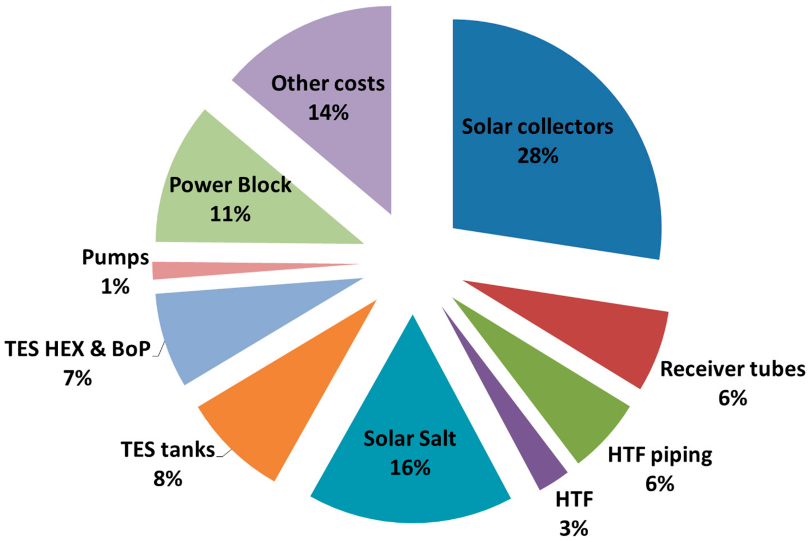
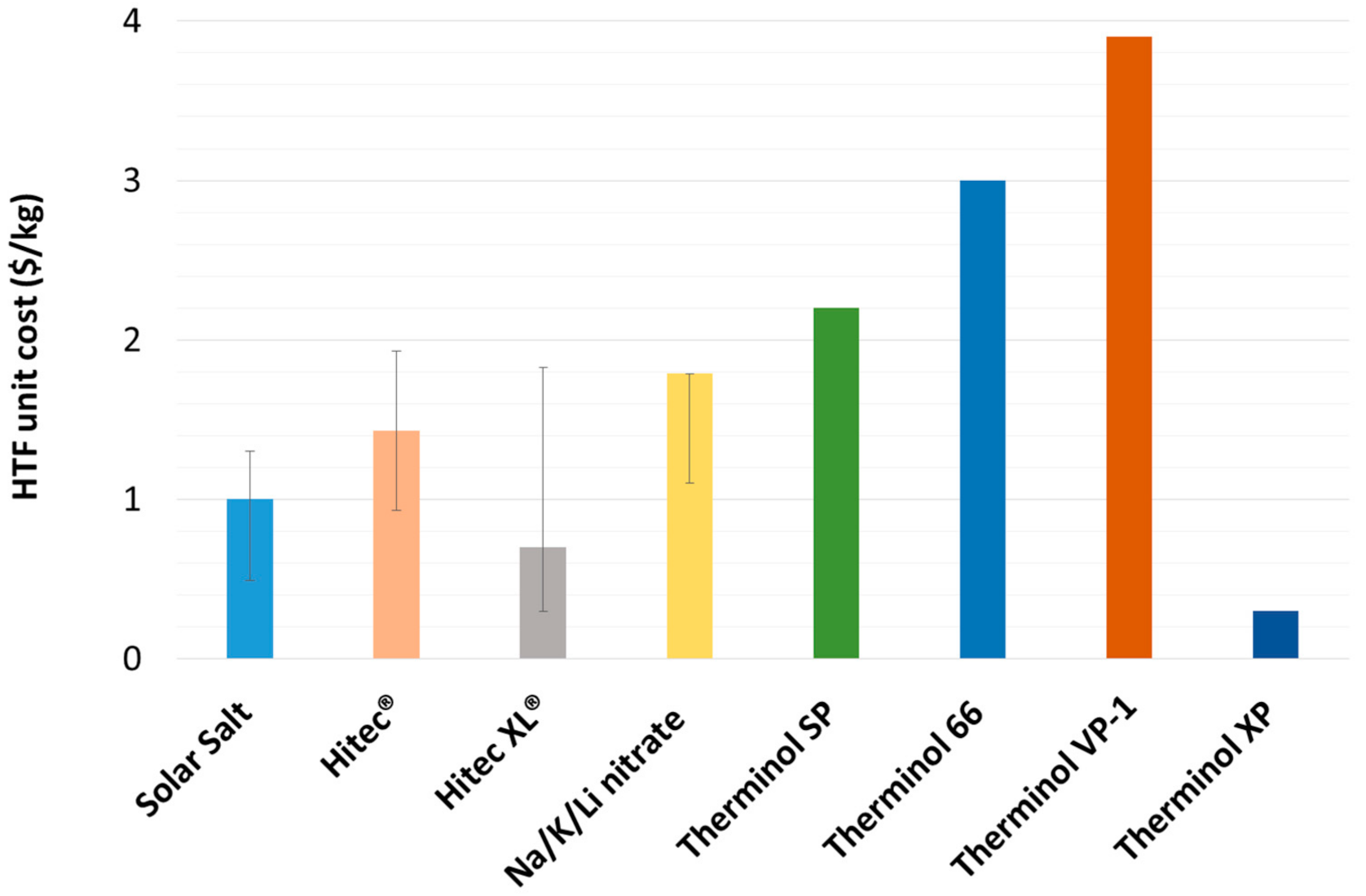
Toxicity and environmental compatibility are clearly major issues for large-scale utilization of heat transfer materials. Table 4 and Table 5 report the safety indications for thermal oils and salts, respectively. In general, salt mixtures are safer than oils which are highly flammable, toxic and pollutant, even not considering the sub-products due to thermal degradation [1]. However, nitrites and lithium can also be harmful for the humans and the environment, and the thermal decomposition of nitrates and nitrites can lead to the formation of nitrogen oxides [25].

2.4. Material Costs

A comprehensive assessment and comparison of HTFs also includes market prices of the fluid to be purchased and of the respective construction materials to be used.
Table 6 reports recent cost ranges for the HTF here considered, resulting from available literature sources. As expected, there are significant oscillations in the reported values. In this work, the authors also considered the prices according to ENEA’s experience obtained in several CSP research projects [49,50]. Figure 8 summarizes the data along with an indication of the literature data sources.
Regarding construction materials, as discussed in a previous section special austenitic stainless steels are needed for applications above 400 °C [16,17]. From the literature, it can be stated that the market prices of these alloys (AISI 321 and 347) are similar to the ones of the other austenitic steels. Carbon steels seem suitable for operative temperatures lower than 400 °C. Table 7 resumes the costs obtained by a preliminary market research; considering averaged values, it is realistic to take 2.73 US$/kg for stainless steels and 0.99 US$/kg for carbon steels. However, it is noteworthy that these values can significantly change due to market fluctuations.

3. Techno-Economic Analysis for CSP Applications

The choice of a specific HTF has different implications on the design of a CSP plant and its performances. In this section the impact of the use of a specific HTF is assessed considering techno-economic aspects at CSP system level, with a semi-quantitative approach.
Figure 9 shows a typical cost breakdown for a 50 MWe “standard” CSP plant with parabolic troughs, synthetic oil HTF (PT-TO) and 6 h thermal storage with the “Solar Salt”, according to the general scheme in Figure 1.
Clearly, for a given power capacity (e.g., 50 MWe) the larger the capacity factor of the plant, the larger will be the size and cost impact of Solar Field and TES, while other costs such as Power Block, pumps and “TES HEX & BoP” remain nearly unaffected by the increased productivity.
In order to compare the different HTFs options at the CSP system level, the PT-TO layout (Figure 1) is taken as benchmark to estimate relative costs and productivity of other solutions.
As far as the plant performance is concerned, changing the thermal fluid has an impact on the operating temperatures of basic units such as the HTF loop, the TES and the steam Rankine cycle. On the one hand, the higher the maximum HTF temperature, the higher will be the Power Block efficiency. On the other hand, the higher the HTF operating temperature the higher will be the heat losses during the HTF circulation in the solar field.
Considering a 50 MWe CSP plant with overall reflective area of the solar field of 735,750 m2, 2.0 solar multiple and 35.6% Power Block efficiency [60], the average solar heat collected by the HTF will be QHTF = 2.0 ∗ (50 MWe)/0.356 = 280.9 MWth; this thermal output (QHTF) results from the difference between the effective solar radiation on solar receivers (Qrec) minus the overall heat losses in the solar field (Qloss):
QHTF = Qrec − Qloss
Qloss can be estimated as function of the average temperature of the HTF in the solar field, as reported elsewhere [13].
For the 735,750 m2 solar field here examined with the HTF temperatures in the range of 293–393 °C (Figure 1) the estimated average heat loss is Qloss = 32.2 MWth and the resulting effective solar radiation on solar receivers is (from Equation (2)) is Qrec = QHTF + Qloss = 313.1 MWth. This value mainly depends on the solar collectors’ optical performances, i.e., geometrical/optical features, rather than on the used HTF. Therefore, Equation (2) can be used to evaluate the effectively collected solar heat when using different HTFs, fixing a constant value Qrec = 313.1 MWth for the assumed plant size.
The overall effect in terms of power output can be determined by the following equation:
Power output = ηt-el·(Qrec − Qloss)
where ηt-el is the efficiency of the Power Block (i.e., the steam Rankine cycle).
In terms of plant design and fixed costs, solar collectors, power block, pumps and other general direct costs are not expected to be significantly affected by a changeover of the HTF. Differently, major cost effects deal with the TES materials and components.
For equivalent heat storage capacity (hours or MWh thermal) the size of the TES system (i.e., volume of the TES tanks and total mass of molten salt) depends on the operative temperatures of the heat storage loop: the larger the temperature difference TS–high − TS–low, the smaller will be the required size (and costs) of the TES system according to the following relationship:
Q TES = M MS · c pMS ·   T S high T S low
where Q TES is the specified heat storage capacity of the CSP plant, M MS is the required total mass of molten salts to be loaded in the TES tanks, and c pMS is the heat capacity of the molten salt used as heat storage medium.
Consequently, for a given heat storage capacity ( Q TES ) the quantity of molten salt required can be determined by the following equation:
M MS = Q TES c pMS · T S high T S low
while the volume of the TES tanks is proportional to M MS divided by the density of the molten salt at TS–high.

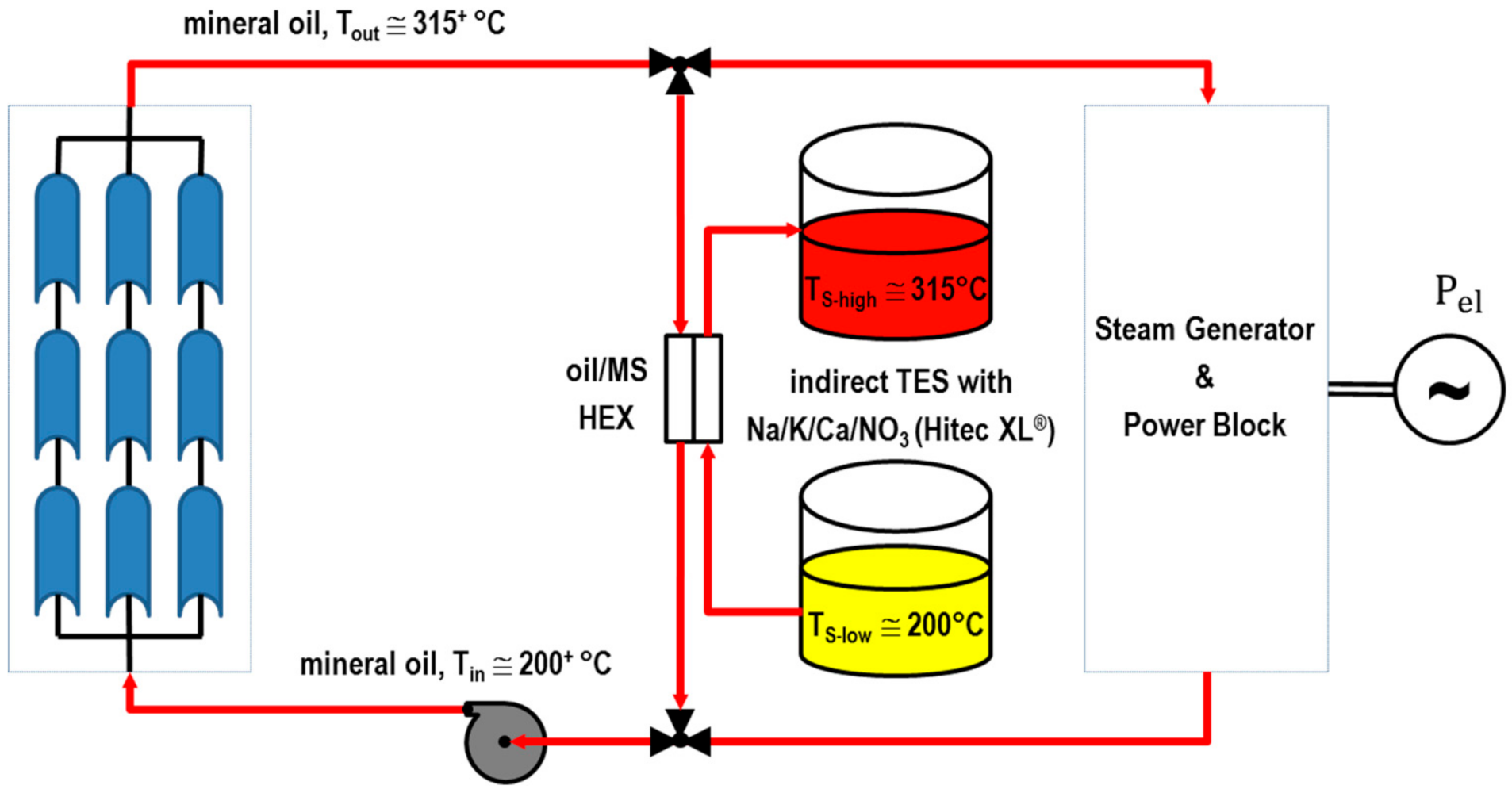
3.1. Different Layouts for Different HTFs

Figure 10 shows the general layout of a PT-TO CSP plant where the synthetic oil is replaced with a mineral oil (e.g., Therminol XP): since the molten salt TES system is still indirectly heated with the thermal oil, this changeover of the HTF does not imply a modification of the general layout of the CSP plant (compared to Figure 1). However, the mineral oil can be operated up to ~315 °C. Under such lower temperature range, for the TES system it is preferable to replace the typical binary solar salt mixture with the ternary Na/K/Ca/NO3 one (Hitec XL®) characterized by lower cost (Figure 8) and wider operation range at lower temperatures: it is possible to use the indirect two-tank TES system loaded with the Hitec XL® salt operating from TS–high ≅ 315 °C to TS–low ≅ 200 °C.
Under these conditions, compared to the benchmark case, lower steam temperature (and pressure) can be obtained, with lower Power Block efficiency, here assumed to be 32.1%, resulting in about 10% loss in power production. However, when the HTF temperature in the solar field range from 200 °C to 315 °C (average: 257.5 °C) evaluated heat losses in the 735,750 m2 solar field will be around Qloss = 15.4 MWth and QHTF = Qrec − Qloss = 313.1 − 32.2 = 297.6 MWth.
In conclusion, replacing the synthetic oil with a mineral oil will reduce the operative temperatures of the HTF loop, with the following effects:
  • decreased Rankine cycle efficiency from 35.6% to 32.1%;
  • reduced heat losses with an increase of the collected solar heat by about 6%;
  • net effect on productivity, according to Equation (3), being about 4% reduction of power output.
The cost of the mineral oil HTF is marginal when compared to the synthetic oil (see Figure 8). The cost of the salt (Hitec XL®) to be loaded the TES system is slightly smaller than the one of the solar salt in the reference synthetic oil case, mainly thanks to the wider temperature difference (TS–high − TS–low) and to the lower cost of the ternary Na/K/Ca/NO3 mixture compared to the binary “solar salt” mixture (Figure 8). The volume of the TES tanks remains almost unaffected due to the relatively smaller energy density of the Hitec XL® molten salt (Figure 7).
In conclusion, replacing the traditional synthetic oil with a mineral oil HTF will not significantly change the CSP plant layout but the lowering of the operative temperatures will reduce both the overall power productivity (~−4%) and the fixed direct costs (~−4%).
Figure 2 shows the general layout of a PT-MS CSP plant with solar salt (binary Na/K/NO3 mixture) and direct TES up to 550 °C.
The increased maximum temperature of the HTF cycle from ~393 °C to 550 °C has a positive effect on the efficiency of the Rankine cycle; however, due to the higher heat losses, there isn’t any expected relevant difference on plant productivity.
As far as the plant costs are concerned, the changeover of the HTF in the solar field will not significantly affect the costs for the solar collectors; the only relevant extra cost is the auxiliary heating system, by direct Joule effect, needed to pre-heat the solar receivers before flooding the solar field and to manage emergency draining operations [13]. Differently, solar receiver tubes and HTF piping materials for solar salt are more expensive than the ones used for thermal oils: a correction factor of 1.5 can be applied to take into account the higher cost for piping materials. The additional cost due to auxiliary electrical heating of the piping should considered too. According to Figure 8 and Table 6, the cost for the HTF will be at least 1/3 the cost of the synthetic oil. However, the largest difference between solar salt and the synthetic oil (benchmark) is linked with the cost of the TES units: thanks to the wider operation range of the HTF, the TES size will be about 40% smaller, with significant gain in the cost of solar salt inventory and tanks; additionally, in the “direct” solar salt layout the intermediate oil/MS and ancillary instrumentation will not be required.
In conclusion, the changeover from the traditional PT-TO layout with synthetic oil to the direct solar salt PT-MS system results in minor effects on power productivity but significant benefits in terms of plant costs mainly due to the reduction of the TES units (about −15%).
Figure 11 shows the general layout of a PT-MS CSP plant with the ternary mixture with Na/K nitrate/nitrite (Hitec®) up to 530 °C and direct TES storage. In fact, although under air this fluid is unstable above 440 °C, its thermal stability limit can be increased up to 534 °C if it is maintained under inert (e.g., nitrogen) atmosphere [26]. Thanks to the lower freezing temperature, this salt can be operated in a wider temperature range, with the cold molten salt tank around 200 °C.
Thanks to the lower freezing temperature it possible to circulate the HTF at lower temperatures to reduce the heat losses. Overall there is a potential slight increase on plant productivity (~+3%) vs. the benchmark PT-TO case. If compared to the solar salt HTF, the Hitec® requires slightly smaller volumes (and costs) for the TES tanks given its higher energy density per unit volume (Figure 7), but the total cost for the salt is slightly higher due to the higher unit cost of the ternary nitrate/nitrite mixture.
It is noteworthy that the ternary mixture Na/K/NO3/NO2 (Hitec®) also requires ancillary equipment to prevent air to enter the TES system.
In conclusion, the use of the ternary mixture Na/K/NO3/NO2 (Hitec®) results in similar performances than the solar salt. Heat losses are reduced but slightly more complex design of the TES system is required to avoid air contact with the molten salt.
Figure 12 shows the general layout of a PT-MS CSP where the ternary mixture Na/K/Ca/NO3 (Hitec XL®) is used as HTF and heat storage material in a direct TES system.
Thanks to the max operative temperature of the HTF around 425 °C, the efficiency of the thermal cycle is expected to be slightly higher than the reference one (i.e., PT-TO with synthetic oil up to ~393 °C); an overall slight increase of plant productivity is also expected when compared to other molten salt solutions, due to the lower heat losses.
Thanks to the lower price of this HTF, the major cost benefits derive from the overall lower cost of the salt. In total, this solution leads to about 12% savings in terms of CSP plant costs compared with the benchmark PT-TO case. It is also worth noting that, differently from the previous Hitec® case, the TES system can be maintained and operated under atmospheric air, without the necessity of nitrogen inertization.
Figure 13 shows the general layout of a PT-MS CSP when the ternary mixture Na/K/Li/NO3 is applied as HTF and heat storage material in a direct TES system.
Due to the similar temperature range, performances and costs are expected to be similar to the Hitec® case.

3.2. Comparison between the HTFs

In the previous sections it is highlighted that the use of different HTFs has an impact on the design, performances and costs of linear-focusing CSP plants.
As far as the performance is concerned, no major differences are expected (<±5%) between different solutions in terms of overall productivity: the expected gain attainable by higher HTF temperatures, leading to higher Power Block efficiencies, is to some extent vanished when heat losses from the HTF loop are considered.
Differently, the use of different HTFs has a significant impact on CSP plant costs. Figure 14 shows the relative total and breakdown costs for the different CSP plant configurations here investigated. Solar collectors are not expected to sensibly change their cost by the changeover of the HTF; differently the cost of solar receiver tubes and piping will depend on the HTF due to the different temperatures and corrosion issues: a coefficient been applied to adapt the cost of typical carbon steel tubes to stainless steel alloy used with molten salts. Another cost item largely affected by the changeover of the HTF is the solar salt inventory needed as heat storage medium and the TES heat exchanger/BoP, both significantly reduced when the temperatures are increased and the indirect oil/molten salt TES system is converted to direct molten salt.
In general, the changeover of thermal oils to molten salts will increase the cost of the solar field (solar collectors, receiver tubes, HTF piping) but will significantly reduce the cost of the TES components (mainly salt quantity, tanks and heat exchangers). The net effect is a significant reduction of the fixed investment for the CSP plant.
Differences in Operation and Maintenance (O&M) costs are uneasy to estimate due to the different operation scenarios. Besides typical O&M cost factors of the two technologies (PT-TO and PT-MS) the PT-TO system is characterized by higher maintenance costs due to the degradation of the thermal oil, with consequent additional costs for periodical oil refilling, exhaust oil disposal and the replacement of receiver tubes due to hydrogen generation and permeation (through the steel tube) towards the vacuum annulus that reduces the performances of the receiver tubes [63].
All considered, the use of molten salts can lead to significant economic benefits compared to thermal oils (synthetic or mineral). In particular, solar salt and Hitec XL® resulted as the most advantageous HTFs, also considering that they present more favorable safety and environmental features compared the other thermal fluids.

4. Summary and Conclusions

This paper provides an extensive review of the properties of different heat transfer fluids (HTFs) proposed so far for CSP plants with linear concentrators and TES. Besides the physical/chemical properties, different HTFs are analyzed and compared in terms of material corrosion effects, environmental impact and costs. This review highlights the relevant environmental improvements that can be obtained when conventional synthetic oils are replaced with molten salts as HTFs. The extensive review of HTFs was based on data available from the open literature combined with experimental data obtained by the authors to thoroughly compare different solutions.
The different options have also been compared in terms of CSP plant design, costs and performances.
Replacing synthetic oils with mineral oils will not change the general layout of the CSP plant with indirect heat storage (TES) system. A loss of productivity (around 4%) is expected due to the reduction of the maximum operative temperatures (from ~393 °C to ~315 °C) but some savings in plant costs are also expected due to the lower cost of the mineral oil.
It is also highlighted that in CSP plants using (synthetic or mineral) oils as HTF, the ternary mixture Na/K/Ca/NO3 (also known as Hitec XL®) can be used as heat storage medium in place of the typical binary “solar salt” mixture Na/K/NO3: thanks to the lower freezing temperatures and costs of the Ca-containing ternary mixture, the TES system will be more compact and the overall plant costs reduced.
Thermal oils (synthetic or mineral) and molten salt HTF have different application ranges in terms of maximum temperature of the thermal cycle: while mineral and synthetic oils can reach the abovementioned maximum temperatures of ~315 °C and ~393 °C, respectively, molten salts allow reaching maximum temperatures in the range from 400 °C to 550 °C or more. However, the easier management of CSP plants with thermal oils, especially in startup and shutdown operations, makes the use of thermal oils more attractive for the smaller scale CSP application range (~1 MWe or less).
When the thermal oil is replaced with molten salts, the general design of solar collectors (still representing the larger cost item of a CSP plant) remains unaltered, but the cost of the solar field increases to some extent, mainly due to the following reasons:
  • need to apply an auxiliary (electrical) heating system with transformers to heat up the solar receiver tubes by direct Joule effect during plant start-up (flooding) and to manage emergency operations [13];
  • electrical tracing and thicker thermal insulation of the HTF piping to prevent freezing of the molten salt;
  • more expensive piping materials (stainless steel, e.g., ASTM 321H) should be used with molten salts, especially in piping sections where the higher temperatures (>400 °C) can be reached.
Differently, the use of molten salts as HTF leads to relevant cost reduction in the TES system design, mainly for the following reasons:
  • avoidance of oil/MS heat exchangers and ancillary equipment related to the indirect TES system;
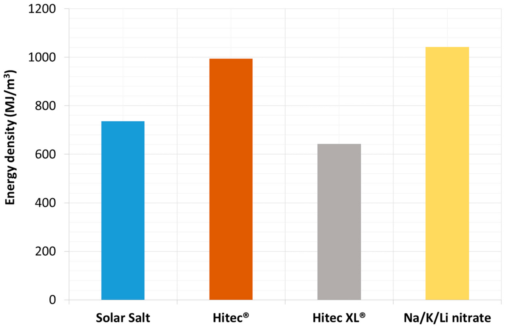
  • use of smaller TES tanks with relevant savings in the procurement of the salt mixture and molten salt tanks.
The net effect is a significant reduction (>10%) of overall cost (CAPEX) for the CSP plant.
It is worth observing that the above assessment was made assuming typical CSP plants with “medium size” heat storage capacity, i.e., in the range of 6–8 h [5,60]. However, CSP plants with larger TES size (up to 16 h or more) are expected to be developed in the future due to the increasing importance of “dispatchability” in the management of power grids with increasing penetration of vRES (variable Renewable Energy Sources) and technologies such as PV and wind [64]. The lower cost impact of the TES in CSP plants with molten salt HTF will make the molten salt technology even more convenient from economic perspectives.
This economic competitiveness can be further improved by developing innovative solutions/methods that will reduce the impact of the abovementioned factors that make the cost of the solar field more expensive.
Minor differences are expected (<±5%) in terms of overall power productivity of the CSP plant when the thermal oil is replaced with molten salts. Although the higher temperatures achievable with molten salts allow reaching higher efficiencies of the thermo-electric generation cycle, this gain is (to some extent) lost by the higher heat losses in the HTF loop occurring during solar collection periods and night circulation of the HTF in the solar field.
As far as operation and maintenance (O&M) costs are concerned, the thermal oil technology is expected to show higher maintenance costs due to the degradation of the thermal oil (i.e., additional costs for periodical oil refilling, exhaust oil disposal and the replacement of damaged receiver tubes due to hydrogen generation and permeation through the steel tube).
Finally, the following conclusions are drawn from the comparison of the different molten salt solutions considered in this paper:
  • ternary mixtures such as Na/K/NO3/NO2 (Hitec®) and Na/K/Li/NO3 show similar performances in terms of operative temperature range, heat losses, productivity, compactness of the TES tanks and costs;
  • the ternary mixture Na/K/NO3/NO2 (Hitec®) requires a slightly more complex design of the TES system to avoid air contact with the molten salt in the TES tanks;
  • the “solar salt” binary mixture (Na/K/NO3) and the ternary mixture Na/K/Ca/NO3 (Hitec XL®) show lower costs than other HTFs;
  • the ternary mixture Na/K/Ca/NO3 (Hitec XL®) has lower max operative temperature (~425 °C) which reduces the efficiency of the thermal cycle but, thanks to the lower heat losses, net productivity is expected to be similar or even slightly higher than other PT-MS cases;
  • Solar Salt and Hitec XL® show particularly favorable characteristics in terms of toxicity and environmental compatibility;
  • technical issues with pumping and heat transfer may arise with Hitec XL® and Na/K/Li/NO3 due to their high viscosity (Figure 4) when the temperature approaches the lower limit (here assumed 200 °C).
Regarding the salts’ compatibility with construction materials, according to the available literature, the effective performances are more dependent on the working temperature than on the chemical composition of the salt mixture. As a rule, carbon steel can be considered for tanks and pipelines below 400 °C, while special stainless steels, such as AISI 321 and 347, should be used at higher temperatures.

Author Contributions

Conceptualization and methodology: A.G., A.C.T. and S.S.; investigation, validation, data curation and formal analysis: A.G., A.C.T., S.S., N.C., E.M., A.S. and T.D.; supervision: A.G., A.C.T. and S.S.; writing—original draft preparation, review and editing: A.G., A.C.T., S.S., A.S. and T.D.; project administration: A.G.; funding acquisition: A.G. All authors have read and agreed to the published version of the manuscript.

Funding

This research was funded by the Italian Ministry of Ecological Transition.

Institutional Review Board Statement

Not applicable.

Informed Consent Statement

Not applicable.

Data Availability Statement

Several literature data are used in the article, and their source is duly cited in the text.

Acknowledgments

The results presented in this paper have been obtained in the framework of the “Concentrating Solar Power” project, under the “Electric System Research” program 2019–2021, with the financial support of Italian Ministry for Ecological Transition.

Conflicts of Interest

The authors declare no conflict of interest.

Glossary

DefinitionNomenclatureUnits
Specific heat cp kJ kg   K
Thermal conductivityk W m   K
Dynamic viscosity μ Pa s
Density ρ kg m 3
Efficiency of the Power Blockηt-el%
Molten salt Mass loaded in the TESMMSkg
Collected Solar heat in solar fieldQHTFMW thermal
Solar radiation on solar receiversQrecMW thermal
Heat losses in the solar fieldQlossMW thermal
Heat storage capacityQTESMW thermal (or hours)
Timetsec. or hours
Maximum temperature of the HTF loop and TES systemTS–high°C
Minimum temperature of the HTF loop and TES systemTS–low°C

Abbreviations

Balance of PlantBoP
Corrosion RateCR
Concentrating Solar PowerCSP
Carbon SteelC-steel
Diphenyl OxideDPO
Heat ExchangerHEX
Heat Transfer FluidHTF
Molten SaltMS
Not availablen.a.
Operation and MaintenanceO&M
Parabolic TroughPT
Parabolic Trough with Molten Salt HTFPT-MS
Parabolic Trough with Thermal Oil HTFPT-TO
Static and Dynamic (for corrosion tests)S/D
Solar Tower with Molten Salt HTFST-MS
Thermal Energy StorageTES
Thermal OilTO
variable Renewable Energy SourcevRES

References

  1. Islam, M.T.; Huda, N.; Abdullah, A.B.; Saidur, R. A comprehensive review of state-of-the-art concentrating solar power (CSP) technologies: Current status and research trends. Renew. Sustain. Energy Rev. 2018, 91, 987–1018. [Google Scholar] [CrossRef]
  2. Pan, C.A.; Guédez, R.; Dinter, F.; Harms, T.M. A techno-economic comparative analysis of thermal oil and molten salt parabolic trough power plants with molten salt solar towers. AIP Conf. Proc. 2019, 2126, 120014. [Google Scholar] [CrossRef]
  3. Grena, R.; Tarquini, P. Solar linear Fresnel collector using molten nitrates as heat transfer fluid. Energy 2011, 36, 1048–1056. [Google Scholar] [CrossRef]
  4. CSP Projects around the World—SolarPACES. Available online: http://www.solarpaces.org/csp-technologies/csp-projects-around-the-world/ (accessed on 4 August 2021).
  5. IRENA Renewable Energy Technologies Cost Analysis Series: Concentrating Solar Power. Available online: https://www.irena.org/-/media/Files/IRENA/Agency/Publication/2012/RE_Technologies_Cost_Analysis-CSP.pdf (accessed on 10 October 2021).
  6. Kearney, D.; Kelly, B.; Herrmann, U.; Cable, R.; Pacheco, J.; Mahoney, R.; Price, H.; Blake, D.; Nava, P.; Potrovitza, N. Engineering aspects of a molten salt heat transfer fluid in a trough solar field. Energy 2004, 29, 861–870. [Google Scholar] [CrossRef]
  7. Piemonte, V.; De Falco, M.; Tarquini, P.; Giaconia, A. Life Cycle Assessment of a high temperature molten salt concentrated solar power plant. Sol. Energy 2011, 85, 1101–1108. [Google Scholar] [CrossRef]
  8. Giostri, A.; Binotti, M.; Astolfi, M.; Silva, P.; Macchi, E. Comparison of different solar plants based on parabolic trough technology. Sol. Energy 2012, 86, 1208–1221. [Google Scholar] [CrossRef]
  9. Bachelier, C.; Stieglitz, R. Design and optimisation of linear Fresnel power plants based on the direct molten salt concept. Sol. Energy 2017, 152, 171–192. [Google Scholar] [CrossRef]
  10. Matino, F.; Procedia, A.M.-E. Molten salt receivers operated on parabolic trough demo plant and in laboratory conditions. Energy Procedia 2015, 69, 481–486. [Google Scholar] [CrossRef] [Green Version]
  11. Maccari, A.; Donnola, S.; Matino, F.; Tamano, S. Archimede solar energy molten salt parabolic trough demo plant: Improvements and second year of operation. AIP Conf. Proc. 2016, 1734, 100007. [Google Scholar]
  12. Gaggioli, W.; Di Ascenzi, P.; Rinaldi, L.; Tarquini, P.; Fabrizi, F.; Di Ascenzi, P.; Rinaldi, L.; Tarquini, P.; Fabrizi, F. Effects assessment of 10 functioning years on the main components of the molten salt PCS experimental facility of ENEA. AIP Conf. Proc. 2016, 1734, 070009. [Google Scholar] [CrossRef] [Green Version]
  13. Giaconia, A.; Iaquaniello, G.; Metwally, A.A.; Caputo, G.; Balog, I. Experimental demonstration and analysis of a CSP plant with molten salt heat transfer fluid in parabolic troughs. Sol. Energy 2020, 211, 622–632. [Google Scholar] [CrossRef]
  14. Morin, G.; Karl, M.; Mertins, M.; Selig, M. Molten Salt as a Heat Transfer Fluid in a Linear Fresnel Collector—Commercial Application Backed by Demonstration. Energy Procedia 2015, 69, 689–698. [Google Scholar] [CrossRef] [Green Version]
  15. Giaconia, A.; Caputo, G.; Ienna, A.; Mazzei, D.; Schiavo, B.; Scialdone, O.; Galia, A. Biorefinery process for hydrothermal liquefaction of microalgae powered by a concentrating solar plant: A conceptual study. Appl. Energy 2017, 208, 1139–1149. [Google Scholar] [CrossRef]
  16. Delise, T.; Tizzoni, A.C.; Menale, C.; Telling, M.T.F.; Bubbico, R.; Crescenzi, T.; Corsaro, N.; Sau, S.; Licoccia, S. Technical and economic analysis of a CSP plant presenting a low freezing ternary mixture as storage and transfer fluid. Appl. Energy 2020, 265, 114676. [Google Scholar] [CrossRef]
  17. Sau, S.; Corsaro, N.; Crescenzi, T.; D’Ottavi, C.; D’Ottavi, C.; Liberatore, R.; Licoccia, S.; Russo, V.; Tarquini, P.; Tizzoni, A.C.; et al. Techno-economic comparison between CSP plants presenting two different heat transfer fluids. Appl. Energy 2016, 168, 96–109. [Google Scholar] [CrossRef]
  18. Frank, M.; Papanikolaou, M.; Drikakis, D.; Salonitis, K. Heat transfer across a fractal surface. J. Chem. Phys. 2019, 151, 134705. [Google Scholar] [CrossRef]
  19. Ma, B.; Shin, D.; Banerjee, D. Synthesis and Characterization of Molten Salt Nanofluids for Thermal Energy Storage Application in Concentrated Solar Power Plants—Mechanistic Understanding of Specific Heat Capacity Enhancement. Nanomaterials 2020, 10, 2266. [Google Scholar] [CrossRef]
  20. Ueki, Y.; Fujita, N.; Kawai, M.; Shibahara, M. Molten salt thermal conductivity enhancement by mixing nanoparticles. Fusion Eng. Des. 2018, 136, 1295–1299. [Google Scholar] [CrossRef]
  21. THERMINOL®66. Available online: http://twt.mpei.ac.ru/TTHB/HEDH/HTF-66.PDF (accessed on 27 July 2021).
  22. SP THERMINOL® SP Heat Transfer Fluids. Available online: https://www.therminol.com/sites/therminol/files/documents/TF-8725_Therminol_SP.pdf (accessed on 26 July 2021).
  23. Therminol VP-1 Heat Transfer Fluid|Therminol|Eastman. Available online: https://www.therminol.com/product/71093459 (accessed on 28 July 2021).
  24. Therminol® XP Heat Transfer Salt. Available online: https://www.therminol.com/sites/therminol/files/documents/TF-8694_Therminol_XP_Technical_Bulletin.pdf (accessed on 26 July 2021).
  25. Delise, T.; Tizzoni, A.C.; Ferrara, M.; Corsaro, N.; D’Ottavi, C.; Sau, S.; Licoccia, S. Thermophysical, environmental, and compatibility properties of nitrate and nitrite containing molten salts for medium temperature CSP applications: A critical review. J. Eur. Ceram. Soc. 2019, 39, 92–99. [Google Scholar] [CrossRef]
  26. HITEC® Heat Transfer Salt. Available online: http://stoppingclimatechange.com/MSR—HITECHeatTransferSalt.pdf (accessed on 1 July 2017).
  27. Zavoico, A.B. Solar Power Tower Design Basis Document, Revision 0; TOPICAL; Semantic Scholar: Albuquerque, NM, USA, 2001. [Google Scholar]
  28. Bauer, T.; Breidenbach, N.; Pfleger, N.; Laing, D.; Eckand, M. Overview of molten salt storage systems and material development for solar thermal power plants. In Proceedings of the 2012 National Solar Conference for (SOLAR 2012), Denver, CO, USA, 13–17 May 2012; pp. 1–8. [Google Scholar]
  29. Delise, T.; Tizzoni, A.C.; Ferrara, M.; Corsaro, N.; D’ottavi, C.; Giaconia, A.; Turchetti, L.; Annesini, M.C.; Telling, M.; Sau, S.; et al. New solid phase of KNO3-NaNO3 salt mixtures studied by neutron scattering and differential scanning calorimetry analysis. AIP Conf. Proc. 2018, 2126, 80001. [Google Scholar] [CrossRef]
  30. Fiorucci, L.C.; Goldstein, S.L. Manufacture, Distribution, and Handling of Nitrate Salts for Solar-Thermal Applications. Contract Report SAND81-8186; Albuquerque, NM, USA, 1982; Available online: https://ui.adsabs.harvard.edu/abs/1982STIN...8321625F/abstract (accessed on 10 October 2021).
  31. Siegel, N.P.; Bradshaw, R.W.; Cordaro, J.B.; Kruizenga, A.M. Thermophysical Property Measurement of Nitrate Salt Heat Transfer Fluids. In Proceedings of the ASME 2011 5th International Conference on Energy Sustainability, Parts A, B, and C, Washington, DC, USA, 7–10 August 2011; pp. 439–446. [Google Scholar]
  32. Delise, T.; Tizzoni, A.C.; Votyakov, E.V.; Turchetti, L.; Corsaro, N.; Sau, S.; Licoccia, S. Modeling the Total Ternary Phase Diagram of NaNO3–KNO3–NaNO2 Using the Binary Subsystems Data. Int. J. Thermophys. 2020, 41, 1–20. [Google Scholar] [CrossRef]
  33. Bradshaw, R. Effect of Composition on the Density of Multi-Component Molten Nitrate Salts. SANDIA REPORT SAND2009-8221. Available online: http://prod.sandia.gov/techlib/access-control.cgi/2009/098221.pdf (accessed on 26 June 2017).
  34. Bradshaw, R.W.; Meeker, D.E. High-temperature stability of ternary nitrate molten salts for solar thermal energy systems. Sol. Energy Mater. 1990, 21, 51–60. [Google Scholar] [CrossRef]
  35. Delise, T.; Tizzoni, A.C.; Ferrara, M.; Telling, M.; Turchetti, L.; Corsaro, N.; Sau, S.; Licoccia, S. Phase Diagram Predictive Model for a Ternary Mixture of Calcium, Sodium, and Potassium Nitrate. ACS Sustain. Chem. Eng. 2020, 8, 111–120. [Google Scholar] [CrossRef]
  36. Coscia, K.; Elliott, T.; Mohapatra, S.; Oztekin, A.; Neti, S. Binary and ternary nitrate solar heat transfer fluids. J. Sol. Energy Eng. 2013, 135, 021011. [Google Scholar] [CrossRef]
  37. ORC-PLUS Final Brochure October 2019. Available online: https://0f4bdca1-3884-4141-9edf-3ee65210ad1e.filesusr.com/ugd/7c3f6b_20fea86a47a44536b8c19e33e8e9d558.pdf (accessed on 29 July 2021).
  38. Kust, R.N.; Burke, J.D. Thermal decomposition in alkali metal nitrate melts. Inorg. Nucl. Chem. Lett. 1970, 6, 333–335. [Google Scholar] [CrossRef]
  39. Wang, J.; Jiang, Y.; Ni, Y.; Wu, A.; Li, J. Investigation on static and dynamic corrosion behaviors of thermal energy transfer and storage system materials by molten salts in concentrating solar power plants. Mater. Corros. 2019, 70, 102–109. [Google Scholar] [CrossRef] [Green Version]
  40. Gomes, A.; Navas, M.; Uranga, N.; Paiva, T.; Figueira, I.; Diamantino, T.C. High-temperature corrosion performance of austenitic stainless steels type AISI 316L and AISI 321H, in molten Solar Salt. Sol. Energy 2019, 177, 408–419. [Google Scholar] [CrossRef] [Green Version]
  41. Helmersson, B.; Navas, M.; Martínez-Tarifa, A.; Wu, R.; Backhouse, A. Molten nitrate corrosion testing and creep data for stainless steels. AIP Conf. Proc. 2020, 2303, 190017. [Google Scholar] [CrossRef]
  42. Kruizenga, A.; Gill, D. Corrosion of Iron Stainless Steels in Molten Nitrate Salt. Energy Procedia 2014, 49, 878–887. [Google Scholar] [CrossRef] [Green Version]
  43. Grosu, Y.; Bondarchuk, O.; Faik, A. The effect of humidity, impurities and initial state on the corrosion of carbon and stainless steels in molten HitecXL salt for CSP application. Sol. Energy Mater. Sol. Cells 2018, 174, 34–41. [Google Scholar] [CrossRef]
  44. Goods, S.H.; Bradshaw, R.W. Corrosion of Stainless Steels and Carbon Steel by Molten Mixtures of Commercial Nitrate Salts. J. Mater. Eng. Perform. 2004, 13, 78–87. [Google Scholar] [CrossRef]
  45. Bradshaw, R.; Goods, S. Corrosion Resistance of Stainless Steels during Thermal Cycling in Alkali Nitrate Molten Salts. SANDIA REPORT SAND2001-8518. Available online: http://infoserve.sandia.gov/sand_doc/2001/018518.pdf (accessed on 26 June 2017).
  46. Optimization of a Thermal Energy Storage System with Integrated Steam Generator|OPTS Project|FP7|CORDIS|European Commission. Available online: https://cordis.europa.eu/project/id/283138/it (accessed on 29 July 2021).
  47. Bradshaw, R.W.; Dawson, D.B.; de la Rosa, W.; Gilbert, R.; Goods, S.H.; Hale, M.J.; Jacobs, P.; Jones, S.A.; Kolb, G.J.; Pacheco, J.E.; et al. Test and Evaluation Results from the Solar Two Project. 2002. Available online: https://www.osti.gov/biblio/793226-final-test-evaluation-results-from-solar-two-project (accessed on 10 October 2021).
  48. Kelly, B.; Barth, D.; Brosseau, D.; Konig, S.; Fabrizi, F. Nitrate and Nitrite/Nitrate Salt Heat Transport Fluids. Available online: https://www.yumpu.com/en/document/read/7510654/nitrate-and-nitrite-nitrate-salt-heat-transport-fluids-nrel (accessed on 30 June 2017).
  49. MATS Project. Available online: http://www.mats.enea.it/ (accessed on 29 July 2021).
  50. STS-Med. Available online: http://www.stsmed.eu/ (accessed on 29 July 2021).
  51. Reddy, R.G. Novel Molten Salts Thermal Energy Storage for Concentrating Solar Power Generation. Available online: https://www.osti.gov/servlets/purl/1111584 (accessed on 10 October 2021).
  52. González-Roubaud, E.; Pérez-Osorio, D.; Prieto, C. Review of commercial thermal energy storage in concentrated solar power plants: Steam vs. molten salts. Renew. Sustain. Energy Rev. 2017, 80, 133–148. [Google Scholar] [CrossRef]
  53. Kearney, D.; Herrmann, U.; Nava, P.; Kelly, B.; Mahoney, R.; Pacheco, J.; Cable, R.; Potrovitza, N.; Blake, D.; Price, H. Assessment of a Molten Salt Heat Transfer Fluid in a Parabolic Trough Solar Field. J. Sol. Energy Eng. 2003, 125, 170. [Google Scholar] [CrossRef] [Green Version]
  54. Gil, A.; Medrano, M.; Martorell, I.; Lázaro, A.; Dolado, P.; Zalba, B.; Cabeza, L.F. State of the art on high temperature thermal energy storage for power generation. Part 1-Concepts, materials and modellization. Renew. Sustain. Energy Rev. 2010, 14, 31–55. [Google Scholar] [CrossRef]
  55. Stainless Steel 321 Plate, Thickness: 1–2 & 3–4 mm, Rs 225 /kilogram|ID: 16882691888. Available online: https://www.indiamart.com/proddetail/ss-321-plate-16882691888.html (accessed on 28 July 2021).
  56. Stainless Steel Plate Aisi 347 China Trade, Buy China Direct from Stainless Steel Plate Aisi 347 Factories. Available online: https://www.alibaba.com/countrysearch/CN/stainless-steel-plate-aisi-347.html (accessed on 28 July 2021).
  57. Stainless Steel 304 Price per kg, Stainless Steel 316 Price. Available online: https://www.stindia.com/stainless-steel-304-316l-price-per-kg-india.html (accessed on 28 July 2021).
  58. China A516 Gr 70 80 mm Thickness Carbon Steel Plate Price—China Carbon Steel Plate, Mild Carbon Steel Plate. Available online: https://xiongyisteel.en.made-in-china.com/product/TOXmPFZckzkb/China-A516-Gr-70-80mm-Thickness-Carbon-Steel-Plate-Price.html (accessed on 28 July 2021).
  59. MetalMiner Prices: Carbon Steel Prices. Available online: https://agmetalminer.com/metal-prices/carbon-steel/ (accessed on 28 July 2021).
  60. Aseri, T.K.; Sharma, C.; Kandpal, T.C. Estimation of capital costs and techno-economic appraisal of parabolic trough solar collector and solar power tower based CSP plants in India for different condenser cooling options. Renew. Energy 2021, 178, 344–362. [Google Scholar] [CrossRef]
  61. A516 Gr 70 Steel Plate Price in China Market on May 28—Bebon Steel. Available online: http://www.bebonchina.com/v3/news/a516-gr-70-steel-plate-price-in-china-market-on-may-28_1124.html (accessed on 28 July 2021).
  62. What is Price of Low-Carbon Steel—Definition|Material Properties. Available online: https://material-properties.org/what-is-price-of-low-carbon-steel-definition/ (accessed on 28 July 2021).
  63. Moens, L.; Blake, D.M. Mechanism of Hydrogen Formation in Solar Parabolic Trough Receivers. J. Sol. Energy Eng. 2010, 132, 0310061–0310065. [Google Scholar] [CrossRef] [Green Version]
  64. Giaconia, A.; Grena, R. A model of integration between PV and thermal CSP technologies. Sol. Energy 2021, 224, 149–159. [Google Scholar] [CrossRef]
Figure 1. General layout of a CSP plant with linear concentrators, synthetic oil HTF and indirect TES system.
Energies 14 07486 g001
Figure 2. General layout of a CSP plant with linear concentrators and direct solar salt used both as HTF and TES medium.
Energies 14 07486 g002
Figure 3. Comparison between the densities of different HTFs.
Energies 14 07486 g003
Figure 4. Comparison between the dynamic viscosity of different HTFs.
Energies 14 07486 g004
Figure 5. Comparison between the heat capacity of different HTFs.
Energies 14 07486 g005
Figure 6. Comparison between the thermal conductivity of different HTFs.
Energies 14 07486 g006
Figure 7. Comparison between the volumetric energy densities of the four salts, considering sensible heat release and average values for densities and heat capacities in the respective operation ranges: 290–550 °C for the Solar Salt; 200–530 °C for Hitec®; 200–425 °C for Hitec XL®; 200–550 °C for Na/K/Li nitrate.
Energies 14 07486 g007
Figure 8. Comparison between the unit cost of different HTFs. Colored bars show the actual values based on ENEA’s experience; error bar include the cost range from different sources.
Energies 14 07486 g008
Figure 9. Typical cost breakdown of a “standard” 50 MWe CSP plant with parabolic trough collectors, synthetic oil HTF and heat storage (6 h). Solar collectors include mirrors, steel structures, foundations, receivers, electronics and electrical equipment. TES tanks include insulation materials and foundations. TES HEX and BoP include the oil/molten salt heat exchanger, ancillary equipment and Balance of Plant (BoP). Other costs include additional general direct costs such as: site improvement, civil works and electrical/mechanical works.
Energies 14 07486 g009
Figure 10. General layout of a CSP plant with linear concentrators, indirect TES and a mineral oil as HTF.
Energies 14 07486 g010
Figure 11. General layout of a CSP plant with linear concentrators and direct molten salt type Hitec® as HTF and TES material.
Energies 14 07486 g011
Figure 12. General layout of a CSP plant with linear concentrators and direct molten salt type Hitec XL® as HTF and TES material.
Energies 14 07486 g012
Figure 13. General layout of a CSP plant with linear concentrators and direct molten salt type Na/K/Li/NO3 as HTF and TES material.
Energies 14 07486 g013
Figure 14. Cost comparison of linear focusing CSP plant designs (50 MWe) using different HTFs, assuming the solution using synthetic oil as reference case. Solar salt is considered as TES medium with synthetic oils and Hitec XL® with the mineral oil.
Energies 14 07486 g014
Table 1. Thermo-physical properties of Therminol 66, Therminol SP, Therminol VP-1 and Therminol XP.
Therminol 66 [21]
Chemical composition (%wt)Hydrogenated terphenyl/Polyphenyls/Terphenyl (81/14/5)
Temperature range0 ÷ 345 °C
Density k g m 3 vs. temperature ° C ρ = 1020.6 0.6 · T + 3.2 · 10 4 · T 2
Dynamic Viscosity [cP] vs. temperature ° C μ = 58,191 · T 2.093
Thermal conductivity [ W K m ] vs. temperature ° C k = 0.1 3.3 · 10 5 · T 1.5 · 10 7 · T 2
Heat capacity [ J ° C g ] vs. temperature ° C cp = 1.5 + 3.3 · 10 3 · T 8.9 · 10 7 · T 2
Maximum film temperature375 °C
Boiling point (1013 mbar)359 °C
Therminol SP/Dowtherm HT [22]
Chemical compositionBenzene, C14-30-alkyl derivatives
Temperature range−10 ÷ 315 °C
Density k g m 3 vs. temperature ° C ρ = 885.6 0.69 · T + 1.9 · 10 4 · T 2 8.9 · 10 7 · T 3
Dynamic Viscosity [cP] vs. temperature ° C μ = 22,321 · T 1.945
Thermal conductivity [ W K m ] vs. temperature ° C k = 0.1 1.1 · 10 4 · T 1.5 · 10 8 · T 2 + 1.8 · 10 11 · T 3
Heat capacity [ J ° C g ] vs. temperature ° C cp = 1.8 + 3.6 · 10 3 · T 4.9 · 10 7 · T 2 7.9 · 10 10 · T 3
Maximum film temperature335 °C
Boiling point (1013 mbar)351 °C
Therminol VP-1 [23]
Chemical compositionEutectic mixture of diphenyl oxide (DPO) and biphenyl
Temperature range−20 ÷ 400 °C
Density k g m 3 vs. temperature ° C ρ = 1083.25 0.90797 · T + 0.00078116 · T 2 2.367 · 10 6 · T 3
Dynamic Viscosity [cP] vs. temperature ° C μ = 171.5 · T 1.155
Thermal conductivity [ W K m ] vs. temperature ° C k = 0.1377 8.19 · 10 5 · T 1.922 10 7 · T 2 + 2.5 · 10 11 · T 3
Heat capacity [ J ° C g ] vs. temperature ° C cp = 1.498 + 0.002414 · T 5.9 · 10 6 · T 2 2.9 · 10 8 · T 3
Maximum film temperature430 °C
Boiling point (1013 mbar)257 °C
Therminol XP [24]
Chemical compositionWhite Mineral Oil
Temperature range−20 ÷ 315 °C
Density kg m 3 vs. temperature ° C ρ = 890.8 0.6 · T + 4.2 · 10 5 · T 2 5.3 · 10 7 · T 3
Dynamic Viscosity [cP] vs. temperature ° C μ = 33,553 · T 1.999
Thermal conductivity [ W K m ] vs. temperature ° C k = 0.1 6.3 · 10 5 · T 1.2 · 10 7 · T 2 1.6 · 10 12 · T 3
Heat capacity [ kJ ° C kg ] vs. temperature ° C cp = 1.7 + 5 · 10 3 · T 2.8 · 10 6 · T 2 + 1.5 · 10 10 · T 3
Maximum film temperature330 °C
Boiling point (1013 mbar)358 °C
Table 3. Corrosion effects for the most used binary and ternary molten salt mixtures.
Molten Salt MixtureSteelCorrosion TestDuration [h]ConditionsT [°C]Ref.Corrosion Rate (µm/Year)Corrosion Products
Solar salt analytical grade
X80 C-steelstatic250Air350[39]20
250N2350[39]10
3000N2350[39]5
3000Air350[39]5
316Lstatic250Air530[39]60
3000Air530[39]10
static250Air550[40]70Fe2O3, Fe3O4
3000Air550[40]9Fe2O3, Fe3O4
static200Air570[41]45
2000Air570[41]10
321Hstatic250Air550[40]110Fe2O3, Fe3O4
3000Air550[40]9Fe2O3, Fe3O4
321SSstatic3000Air600[42]16Fe2O3, Fe3O4
347SSstatic3000Air600[42]16Fe2O3, Fe3O4
Solar salt with 1% chlorides impurity 1%
X80 C-steel 300Air350[39]20
3000Air350[39]5
304static250Air530[39]40
dynamic250Air530[39]60
static2000Air530[39]20
316LS/D250Air530[39]15/40
2000Air530[39]10
600 Ni alloysS/D2000Air530[39]0/5
825 Ni alloysS/D2000Air530[39]0/5
Hitec®
X80 C-steelstatic250Air350[39]15
3000Air350[39]5
304static200Air530[39]110
3000 [39]10
316Lstatic200Air530[39]40
3000Air530[39]5
Hitec XL®
304static1500Air *310[43]7
304static1500Air310[43]7.6
316static1500Air *310[43]4.6
316static1500Air310[43]4.7
* dry salt (200 °C for 12 h).
Table 4. Toxicity, environmental compatibility and safety indications for thermal oils.
HTFToxicityEnvironmental SafetyFlammabilityRegulations
Flash PointSelf-Ignition Point
Therminol 66n.a.H411: Toxic to aquatic life with long-lasting effects170 °C374 °CListed as “Dangerous substances covered by the hazard categories” subject to the qualifying quantities in Seveso III **
Therminol SPH304: may be fatal if swallowed or inhaledH412: Harmful to aquatic life with long-lasting effects177 °C343 °CNot listed as dangerous
Therminol VP-1H315: Causes skin irritation
H332: Harmful if inhaled.
H335: May cause respiratory irritation.
H410: Very toxic to aquatic life with long lasting effects.110 °C621 °CListed as “Dangerous substances covered by the hazard categories” subject to the qualifying quantities in Seveso III **
Therminol XPn.a.Not classified as dangerous for the environment according to the EC Regulation No. 1272/2008.199 °C346 °CNot listed as dangerous
** Direttiva Seveso 2012/18/UE (Seveso III): this Directive lays down rules for the prevention of major accidents which involve dangerous substances, and the limitation of their consequences for human health and the environment, with a view to ensuring a high level of protection throughout the European Union in a consistent and effective manner.
Table 5. Toxicity, environmental compatibility and safety indications for molten salts.
HTFToxicityEnvironmental SafetyFlammabilityRegulations
Solar saltH315: Causes skin irritation
H319: Causes serious eye irritation
H335: May cause respiratory irritation
Not classified as dangerous for the environment according to the criteria of EC Regulation No. 1272/2008.H272—May intensify fire; oxidizer KNO3 Listed as “Dangerous substances covered by the hazard categories” subject to the qualifying quantities in Seveso III **
Hitec®H315: Causes skin irritation
H319: Causes serious eye irritation
H335: May cause respiratory irritation
H350: May cause cancer (oral)
H373: May cause damage to organs (blood, heart, liver) through prolonged or repeated exposure (oral)
H301: Toxic if swallowed.
H410 Very toxic to aquatic life with long lasting effects.
Hitec XL®H302: Harmful if swallowed
H318: Causes serious eye damage
H315: Causes skin irritation
H319: Causes serious eye irritation
H335: May cause respiratory irritation
Not classified as dangerous for the environment according to the criteria of EC Regulation No. 1272/2008.
Na/K/Li nitrateH302: Harmful if swallowed
H315: Causes skin irritation
H319: Causes serious eye irritation
H335: May cause respiratory irritation
Not classified as dangerous for the environment according to the criteria of EC Regulation No. 1272/2008.
* referred to the more dangerous component; ** Direttiva Seveso 2012/18/UE (Seveso III): This Directive lays down rules for the prevention of major accidents which involve dangerous substances, and the limitation of their consequences for human health and the environment, with a view to ensuring a high level of protection throughout the European Union in a consistent and effective manner.
Table 6. Market price ranges for different HTFs.
HTFUnit Cost ($/kg)Ref.
Solar Salt0.5–1.3[45,49,50,51,52,53]
Hitec®0.9–1.9[45,49,50,51,52,53]
Hitec XL®0.7–1.8[45,49,50,51,52,53]
Na/K/Li nitrate1.1–1.8[48,49,50,54]
Therminol SP (synthetic oil)2.2[48,54]
Therminol 66 (synthetic oil) 3.0[48]
Therminol VP-1 (synthetic oil)3.9[54]
Therminol XP (mineral oil)0.3[54]
Table 7. Steels costs obtained by a preliminary market research.
Construction MaterialUnit Cost ($/kg)Ref.
AISI 321 plate3.020[55]
AISI 347 plate1.750[56]
SS 3473.300[57]
Stainless steel2.000–5.000[58,59]
A516 Gr 70 steel plate0.650–0.765[60,61]
Carbon steel0.500[62]
Stainless steel/carbon steel1.700/0.970 (dollar/lb)[59]
Publisher’s Note: MDPI stays neutral with regard to jurisdictional claims in published maps and institutional affiliations.

