1. Introduction
The reduction in pollutant emissions generated during combustion of solid and liquid fuels is one of the emerging issues in power generation [
1,
2]. Various types of pollutants are emitted to the environment during the combustion process. The emission of pollutants results from the composition of the fuel and the conditions of the combustion process [
3,
4]. In practice, both factors occur simultaneously; however, their influence is variable. The most harmful fuel components include sulphur, chlorine and fluorine, which form sulphur oxides as well as hydrochloric and hydrofluoric acids [
5,
6]. In addition, the content of chlorine has an influence on the formation of dioxins [
7].
Supplying an adequate amount of oxygen and proper mixing of the fuel with air are the most important factors in the combustion process and guarantee the complete combustion process [
8]. Otherwise, products such as soot and polycyclic aromatic hydrocarbons (PAHs), which include, e.g., benzo(a)pyrene, are formed [
3]. To a large extent, the emission of particulate matter, especially its finest fraction, which is responsible for the formation of smog, depends on the quality of combustion [
9]. Therefore, this process should be carried out in conditions which allow us to eliminate or reduce the content of most harmful pollutants.
Among solid fuels, apart from hard coal and lignite, various types of biomass and combustible waste are currently used as feedstock for combustion [
10,
11]. The use of biomass for power generation reduces CO
2 emissions, but unfortunately is associated with emissions of particulate matter [
12,
13,
14,
15]. In particular, emissions of particulate matter designated as PM
10 and PM
2.5 are observed. Particulate matter particles are an excellent sorbent for heavy metals, dioxins and PAHs. The sources of the largest emissions of PAHs include solid fuel furnaces of low and medium power, especially furnaces of an old type [
3,
16,
17].
In the case of waste combustion, the process should be carried out at a temperature above 850 °C, with large excess of oxygen (11% O
2 in flue gas). According to the requirements, flue gas has to reach this temperature for at least 2 s to burn off all pollutants. Limiting the furnace output, e.g., by reducing the air supply, lowers the combustion temperature; however, it results in the formation of soot and unburnt hydrocarbons. For example, the formation of benzo(a)pyrene takes place in the temperature range from 300 °C to 600 °C in an oxygen-poor combustion atmosphere [
3,
5,
6,
18,
19]. In turn, dioxins are decomposed at a temperature above 850 °C. This means that conducting the combustion process with reduced furnace output does not match the requirements.
The installations optimized for the combustion process, in particular combustion of biomass and waste, include gasification plants [
20]. The gas produced in the gasification chamber is burned in the burner. This allows us to supply the required amount of oxygen for combustion and guarantees appropriate mixing of the gas with the air [
21]. These conditions are necessary for the complete combustion with minimal emissions of NOx, CO and PAHs. An advantage of separating the gasification and combustion processes is the possibility of continuous purifying of the process gas before combustion. The process gas contains particulate matter, often characterized by a low melting point of approximately 800–1200 °C [
8]. In the combustion chamber, these particles undergo melting and form an insulating layer on the heat exchanger surface. As a result, the heat transfer intensity decreases and the risk of high-temperature corrosion increases.
Particulate matter removal systems are used to remove solid particles from the process gas. Unfortunately, the components of such a system must be resistant to high temperatures, because the gas leaving the gasification chamber has a temperature between 400 °C and 600 °C. The temperature of the gas cannot be lower because the tar condensation point is below 350 °C. As a result, tar is deposited on the elements of particulate matter removal installation and reduces its efficiency. Effective particulate matter removal from flue gas, especially the removal of particles of a size below 2.5 μm, is crucial for reducing the emissions of benzo(a)pyrene. Its level in the atmospheric air in Poland is several times higher than in other European countries [
1].
Despite the presented issues of direct and indirect application of biomass for power generation, the participation of biomass in energy sources is expected to increase [
22,
23,
24]. This, however, requires the development of efficient technologies for purification of flue gas and by-products generated in the process of biomass-to-energy conversion [
25,
26,
27].
A large variety of biomass-to-energy conversion technologies have been proposed, including gasification [
28,
29], conversion to liquid fuels [
30,
31] and co-combustion with conventional solid fuels [
11,
14]. The gasification process seems to be the most promising solution, because of the potential use of process gas for both heat and power generation, as well as the possibility to supplement natural gas with purified process gas [
23,
32,
33]. Furthermore, it is even possible to use process gas to operate fuel cells [
34].
For this reason, the purpose of this study is to examine the possibility of the application of a ceramic filter in a biomass gasification plant, as well as to check its efficiency in particulate matter removal from the generated process gas and flue gas. An advantage of this type of filter is a high efficiency in removal of fine particles, even with a size up to 1 µm. This allows much lower particulate matter emissions to be obtained than would result from the requirements of the regulation on emission standards for combustion of waste [
9,
35,
36]. The permissible particulate matter emission for biomass combustion according to [
35] is 30 mg/m
3 (N) and 10 mg/m
3 (N) in the case of waste combustion.
The filtering candles used in ceramic filters are characterized by high durability. Manufacturers declare a lifetime exceeding 5 years. The operating temperature of the filtering candles is 600 °C. Ceramic filters, similarly to bag filters, require regeneration with an oppositely-directed stream of compressed gas. In the case of exhaust gas, compressed air or nitrogen is used for regeneration.
2. Research Methodology
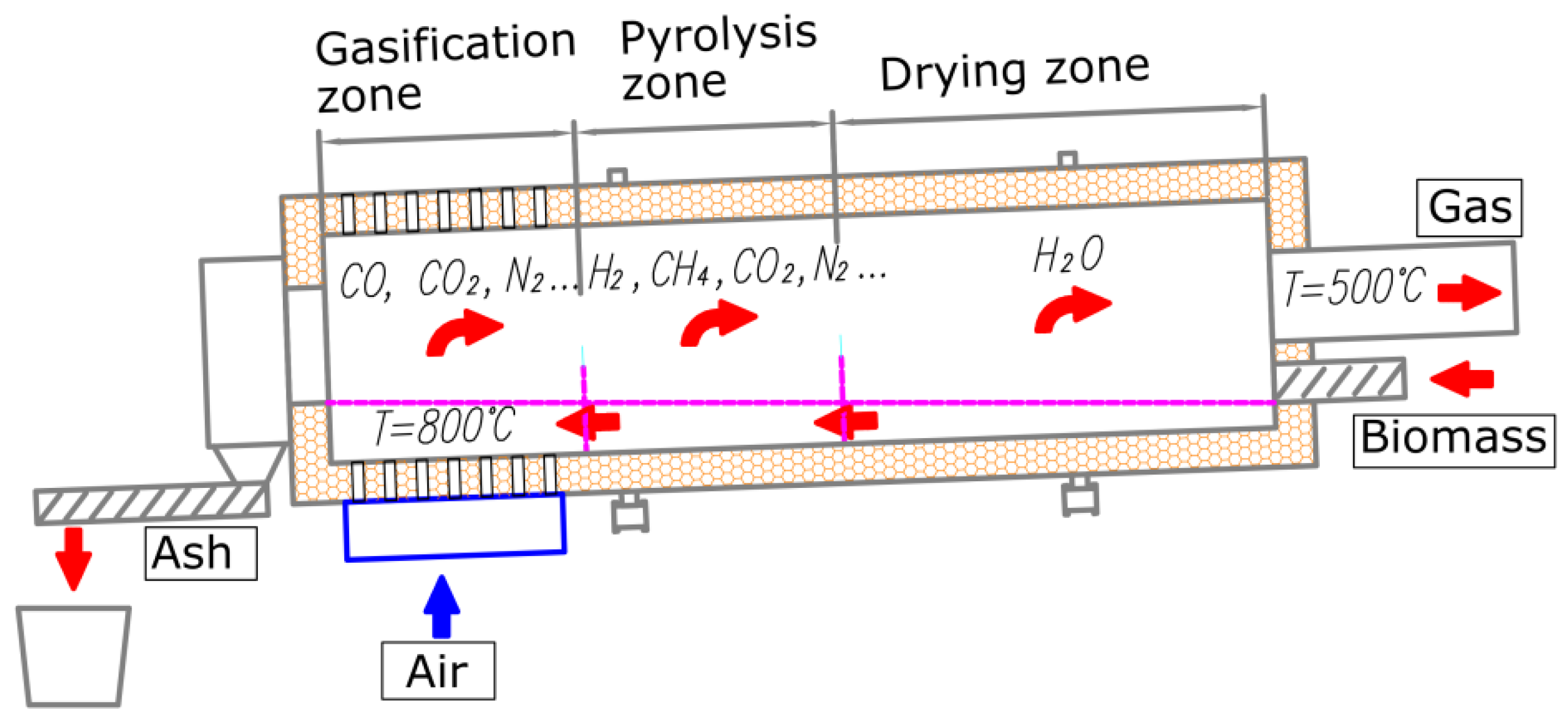
During the tests, the installation was filtering the gas from conifer sawdust particulate matter biomass gasification. The thermal power of the installation, equal to 2 MW, was utilized for biomass drying. The gasification process was performed in a rotary gasification chamber, shown in
Figure 1.
The rotary combustion chamber used in the study is an advanced enhancement of a counter stream gasification chamber. Rotary gasifiers belong to one of the most promising gasifier constructions among different types of gasifier design [
37,
38]. The developed gasification chamber is a tubular structure with internal ceramic coating, installed at 2.5° (referring to the horizontal axis) on the driving rollers.
The sliding seal fuel inlet and process gas outlet are located on the upper side. The bottom side of the chamber is equipped with a sliding seal and rotary feeder for ash removal. The air for the gasification is introduced by crevice nozzles, located at the circuit of the bottom side of the chamber. The air nozzles are controlled by a gears system, which enables the air flow only through bottom nozzles, covered by the biomass layer.
The gasification is an autothermal process. External fuel is used only for installation start-up, in order to heat up the chamber’s internal coating. Biomass of 40% humidity is introduced to the chamber through the upper side. The rotation of the chamber results in movement of the biomass material along the chamber in the direction of air nozzles. The material is heated with generated hot gas, which flows in the opposite direction towards the material. In stable conditions, the temperature inside the chamber varies from 500 °C (upper part) to 900 °C (air nozzles zone) along the chamber. Initially, the biomass material undergoes drying, then, in the hotter zones, degasification, and finally, in the nozzles zone, the material is practically free from volatile content. In the nozzles zone, the gasification and partial combustion occurs, resulting in the formation of ash, containing 0.5% carbon. The process occurring in the nozzles zone is controlled to preserve the exothermal character of the process. This allows the autothermal continuous operation of the chamber. The control of the process is based on accurate adjustment of the air flow through the nozzles. The increase in the air flow rate results from the increase in the process temperature and lowered content of carbon in the ash; however, it decreases the calorific values of the process gas. This is due to higher content of N2 and CO2 as well as a lower content of CO. Optimal process conditions are gained by the air flow rate supplying 30% of the stoichiometric amount of oxygen required for biomass combustion. The process gas formed in the gasification chamber is characterized by a calorific value ranging from 5.0 to 6.5 MJ/m3(N).
This study on the possibility of the application of a ceramic filter and its efficiency in particulate matter removal was performed on an experimental installation, developed by the authors of the paper.
Due to the high capacity of the gasification installation, the gas stream directed to the ceramic filter was only a 20% fraction of the total stream of process gas. This was due to the fact that the prototype filter had a limited capacity.
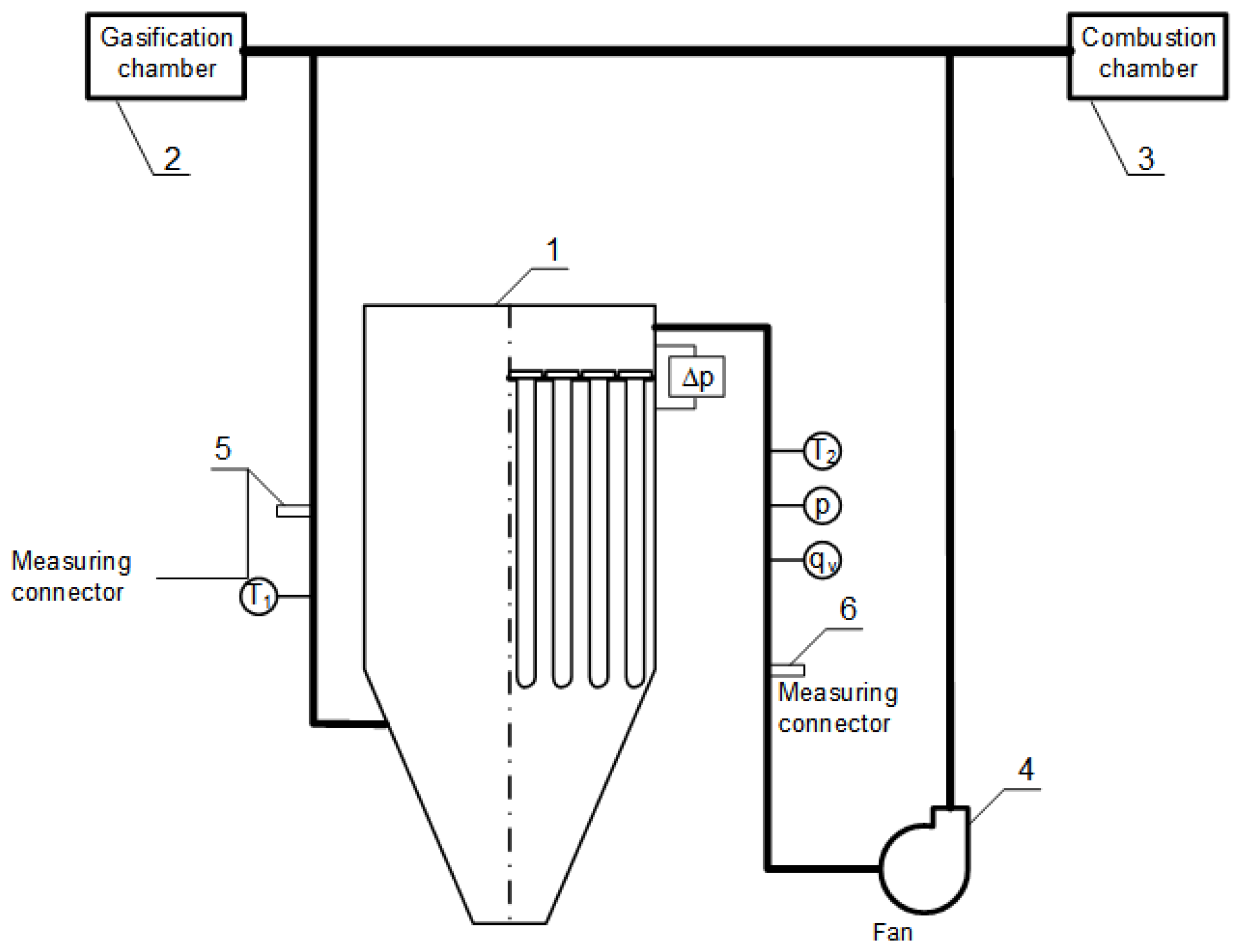
A scheme of the installation is presented in
Figure 2. The main elements of the installation are: (1) ceramic filter, (2) gasification chamber, (3) combustion chamber, (4) fan, (5, 6) measuring connectors.
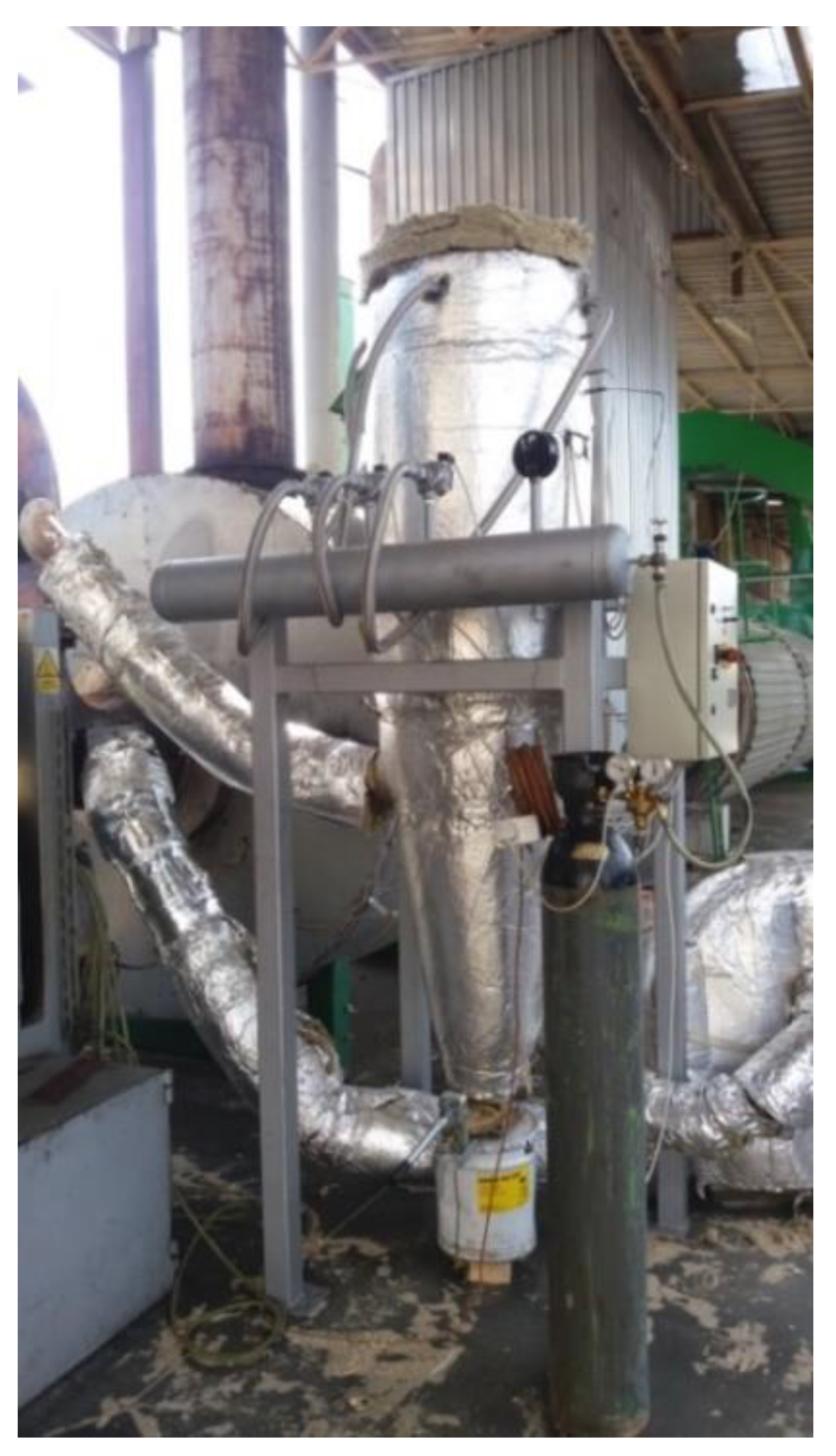
The main element of the system is the filter (1), shown in
Figure 3, equipped with 19 ceramic filtering candles with a diameter of 60 mm and a length of 1 m, with a nominal capacity of 370 m
3/h. The gas from the duct connecting the gasification chamber (2) with the combustion chamber (3) is directed to the filter. The volumetric flow rate of the collected gas constituted approximately 20% of the total volume of the process gas produced in the gasification chamber. The gas flow through the filter was forced by the fan (4) installed downstream of the filter. After purification, the gas was directed into the duct upstream of the combustion chamber.
According to
Figure 2, the stub pipes, designated as (5) and (6), were installed at the inlet and outlet of the filter to collect samples for the analysis of the content of particulate matter in the gas. The temperature values at the inlet
T1 and outlet
T2 of the filter were measured with an accuracy of 1 °C, and pressure
p and the pressure drop Δp on the filtering components were measured with an accuracy 10 Pa. Additionally, the volumetric flow rate
qv of the gas was measured during the test (using a Pitot tube).
The process gas obtained during the gasification of the biomass formed by conifer sawdust was used in the test.
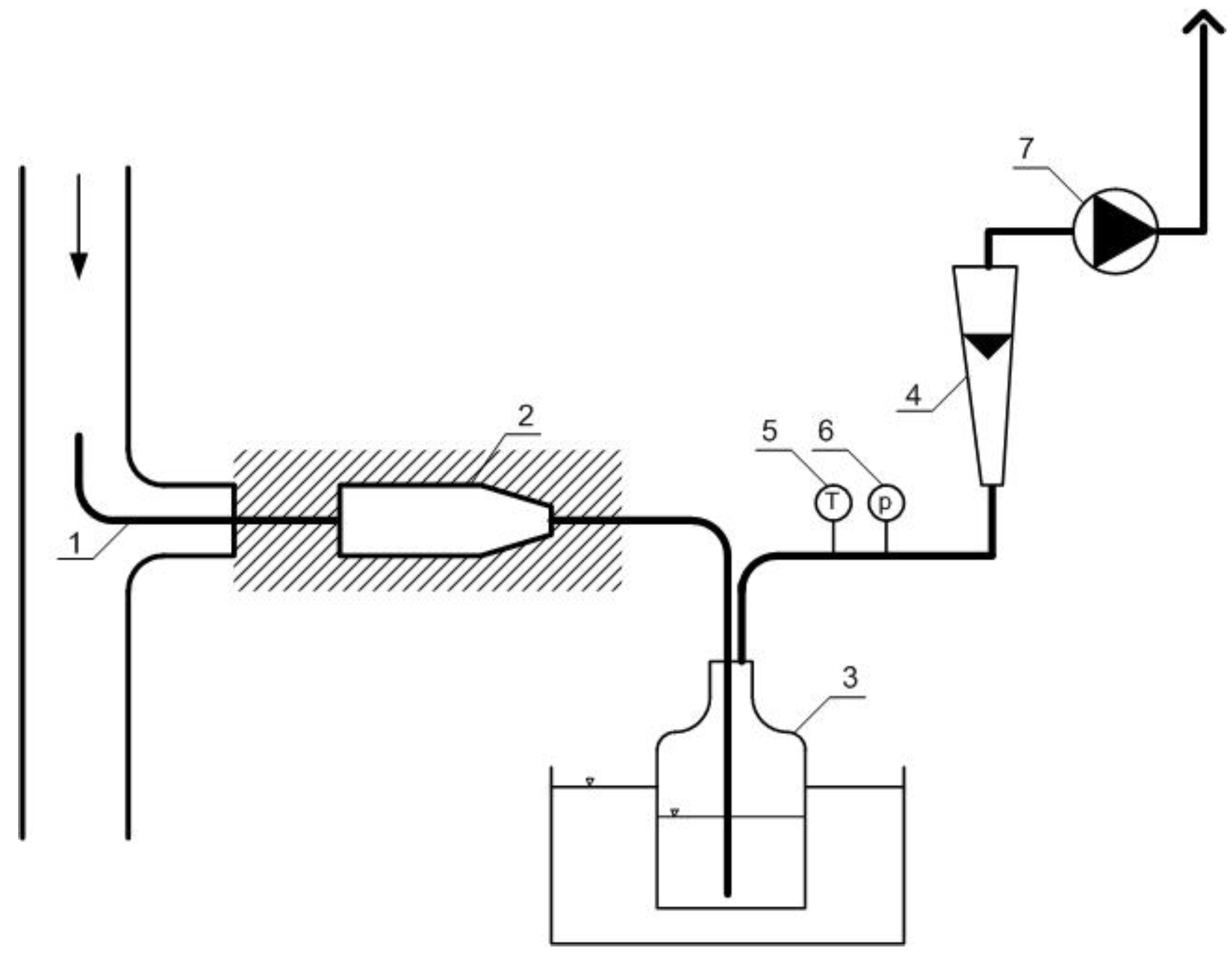
The method of gas intake for testing purposes is shown in
Figure 4. The system consisted of a thermally insulated probe (1) connected to the metal container (2) from a water-cooled scrubber (3), where the gas was cooled and the condensate was collected, a flow meter (4), gas temperature sensors (5) and gas pressure sensors (6), as well as a vacuum pump (7). Mineral wool filter, which was preliminarily weighed, was placed in the container (2). Gas samples were collected in isokinetic manner by adapting the gas flow rate in the probe to the gas flow rate in the pipeline, from which the sample was collected. Three samples were collected at the inlet and outlet of the filter at a steady volumetric flow rate of the gas. Gas samples of approximately 1 m
3 each (in reference to normal conditions) were collected during the test. Subsequently, the collected samples were weighed and washed with toluene to flush out the condensed tar. The washing was repeated until a solid mass of the sample was obtained. The last stage consisted of sample drying. The results obtained were compared to normal conditions.
The measurements of the particulate matter content in the flue gas at the outlet of the combustion chamber have been performed using the above-mentioned method. However, there was no toluene treatment of the samples needed, as the flue gas does not contain tar.
CHNS elemental analysis was performed with the use of a Perkin Elmer 2400 series II analyzer. Measurements of ash content (PN-EN 14775:2010—gravimetric method) and an analysis of volatile components (PN-EN 15148: 2010—gravimetric method) in the sample of particulate matter separated in the filter were carried out. During the tests, an analysis of the process gas was performed using a GAS 3160 gas analyzer.
During the filter tests, particulate matter content in the process gas was measured at the inlet and at the outlet of the filter. Additionally, particulate matter content in the flue gas was also measured, for comparison with the flue gas obtained from combustion of non-filtered process gas.
3. Results of the Measurements and Their Analysis
The results of the measurements of the particulate matter content in the process gas upstream and downstream of the filter are summarized in
Table 1, the results of the measurements of particulate matter collected from the filter are given in
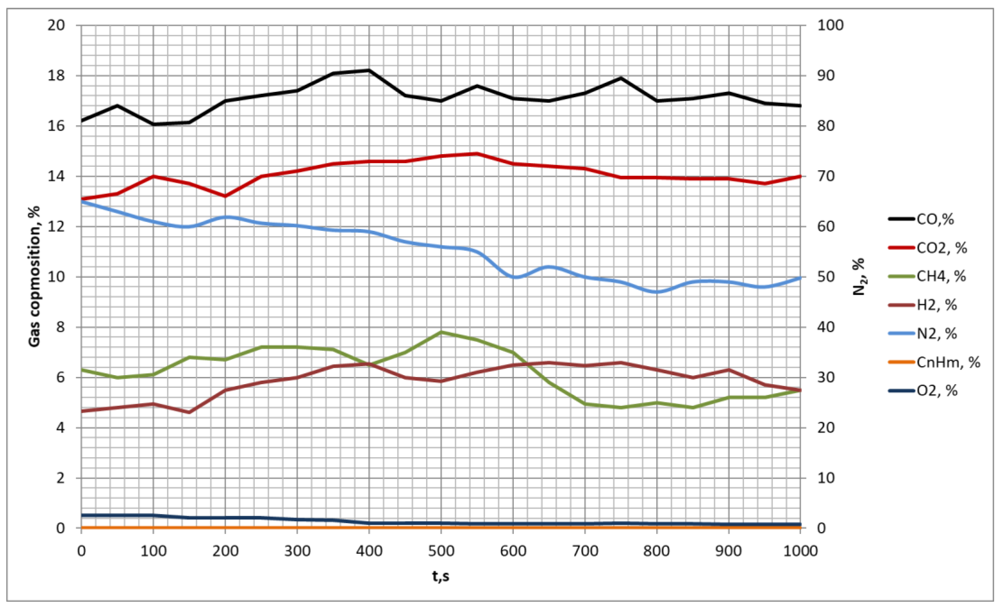
Table 2, while the results of the measurements of the process gas composition are presented in
Table 3 and in a graphic form in
Figure 5.
The results of the particulate matter content in the process gas before and after the filtration have been collected in
Table 1.
Table 2 presents the analysis of particulate matter collected from the ceramic filter, while
Table 3 presents the results of the particulate matter content in the flue gas with and without filtering of the process gas. The composition of the process gas is presented in
Table 4 (average values) as well as in
Figure 5, which presents gas composition in time.
As shown in
Table 1, the average measured particulate matter content in the process gas upstream of the ceramic filter is 2257 mg/m
3(N), while downstream of the filter is as low as 19.53 mg/m
3(N). The particulate matter removal efficiency ƞ was calculated based on the Formula (1):
where:
mi—particulate matter concentration at the filter inlet,
mo—particulate matter concentration at the filter outlet, mg/m
3.
This means that the efficiency of particulate matter removal by the proposed ceramic filter is 99.1%. Application of the filter allowed us to collect the sample and analyze the particulate matter separated from the process gas. The ash content in the collected particulate matter sample is 18.26% (
Table 2) and the rest (81.74%) is made up of combustible components.
The analysis of the particulate matter shows that it is mostly composed of combustible components, which are combusted in the chamber during the process. On this basis, it is predicted that combustion of the gas will further reduce the particulate matter content, below the value measured downstream of the filter—19.53 mg/m3 (N). Additionally, combustion of the gas–air mixture results in dilution of the particulate matter in a larger volume.
During the filter tests, particulate matter content in the flue gas was measured before and after the filtering process. The measured values are 150 mg/m3 and 120 mg/m3, respectively. However, one has to emphasize that only 20% of the total stream of the flue gas was directed to the filter. Based on the above-mentioned measurements, the expected particulate matter content was calculated, which corresponds to filtering the entire process gas stream.
In order to estimate the final particulate matter content in the flue gas, in the first step the theoretical oxygen demand for combustion of the process gas was calculated based on the equation:
where:
O2,
CO,
H2,
CH4,
C2H2 denote the volumetric fraction of the content of individual components in the gas. The expression m
3/m
3(N) refers to m
3 of oxygen per m
3 of process gas.
The theoretical oxygen stream determined from Formula (2) for the combustion of gas with the composition shown in
Table 4 is O
2t = 0.2266 m
3/m
3 (N). In the next step, the theoretical air stream was calculated based on the equation:
The value of
VAIR = 1.08 m
3/m
3(N), calculated from the Formula (3). The flue gas flow rate downstream of the combustion chamber was calculated from the Formula (4):
from which
Vsp = 2.015 m
3/m
3 (N). The excess air factor
λ = 1.5 was adopted for the calculations, as this value was found to be optimal during earlier tests on the installation.
Using the calculated value of the volumetric stream of flue gas, the average value of the particulate matter content at the inlet of the filter and the ash content in the particulate matter collected from the filter were measured, and the resulting particulate matter content in flue gas after the combustion of the process gas can be estimated based on the following equation:
After substituting appropriate values into Equation (4), the calculated particulate matter content in flue gas is 2.04 mg/m3 (N). This value is about 11 times lower than the value of the measured particulate matter content directly at the outlet of the filter.
Estimated particulate matter content is consistent with the measurement results. In the case of filtration of one-fifth of the total gas stream, the measured value of the particulate matter content decreased from 150 mg/m3 (N) before the filtering of the process gas, to 120 mg/m3 (N). The calculated (Equation (1)) efficiency of particulate matter removal from the process gas at the inlet of the combustion chamber is 99.1%. If the proposed method of estimating the particulate matter content in the flue gas downstream of the combustion chamber is taken into account, it can be stated that the final particulate matter content in the flue gas will be below 2 mg/m3(N). Substituting mo = 2 mg/m3 into Formula (1), the reduction in the concentration of the particulate matter in flue gas with the use of the ceramic filter is obtained at a level of over 99.9%.
4. Conclusions
The paper presents the study on the application of a ceramic filter in the biomass gasification process and its efficiency in particulate matter removal from the process gas and flue gas. A significant advantage of this type of filter is its high efficiency in small particle removal (<1 µm). This feature allows us to reach much lower emissions than are required by the applicable standards.
The study was performed using an original biomass gasification installation, where conifer scobs were used as feedstock. The installation, its operation and measurement methodology are described in the article. The study included the analysis of process gas, analysis of the gas filtering process, as well as particulate matter content before and after the filter was applied. The measurements indicate that the efficiency of particulate matter removal reaches 99.1%. Additionally, particulate matter content in flue gas with and without filtering was also measured. Based on average values, it was indicated that filtering of the entire process gas stream would result in particulate matter content in the flue gas at the level of several mg/m3 (N).
The performed process gas particulate matter composition analysis indicated that it contained combustible components. In order to estimate the particulate matter content in the flue gas, a specific estimation method has been developed. The estimation procedure is based on the measured content of the combustible part of the particulate matter collected on the filter and the measured process gas composition. Based on the abovementioned parameters, it was calculated that flue gas particulate matter content will be reduced 11 times when compared to the particulate matter content in the filtered process gas. It was indicated that the estimated values of the flue gas particulate matter content are consistent with the measurements. The presented estimation method allowed us to determine the total effectiveness of the flue gas particulate matter removal by the use of a ceramic filter. The flue gas particulate matter content was at the level of 2 mg/m3 (N), which corresponds to a total particulate matter removal efficiency of 99.9%.
The performed study shows that pre-combustion particulate matter removal is preferred over post-combustion particulate matter removal from flue gas. The reason is that the stream of process gas is several times smaller than the flue gas stream, thus the required size of the filter is smaller. Furthermore, process gas filtering allows us to keep the heat transfer surfaces clean, which preserves high thermal efficiency and durability of equipment.
The presented results of performed tests are the early stage of development of the technology of process gas refining in the waste gasification process. The final target is to reach standards similar to those in the case of natural gas.


