Article

Experimental Oxygen Mass Transfer Study of Micro-Perforated Diffusers

by
Robert Herrmann-Heber
1,*,
Florian Ristau
1,
Ehsan Mohseni
1,
Sebastian Felix Reinecke
1 and
Uwe Hampel
1,2
1
Department of Experimental Thermal Fluid Dynamics, Institute of Fluid Dynamics, Helmholtz Zentrum Dresden-Rossendorf, Bautzner Landstraße 400, 01328 Dresden, Germany
2
Chair of Imaging Techniques in Energy and Process Engineering, Technische Universität Dresden, 01062 Dresden, Germany
*
Author to whom correspondence should be addressed.
Energies 2021, 14(21), 7268; https://doi.org/10.3390/en14217268
Submission received: 10 September 2021 / Revised: 18 October 2021 / Accepted: 28 October 2021 / Published: 3 November 2021
(This article belongs to the Special Issue Water and Wastewater Treatment- Energy Efficiency)

Abstract

:
We studied new micro-perforated diffuser concepts for the aeration process in wastewater treatment plants and evaluated their aeration efficiency. These are micro-perforated plate diffusers with orifice diameters of 30 µm, 50 µm and 70 µm and a micro-perforated tube diffuser with an orifice diameter of 50 µm. The oxygen transfer of the diffuser concepts is tested in clean water, and it is compared with commercial aerators from the literature. The micro-perforated tube diffuser and micro-perforated plate diffusers outperform the commercial membrane diffusers by up to 44% and 20%, respectively, with regard to the oxygen transfer efficiency. The most relevant reason for the improved oxygen transfer is the fine bubble aeration with bubble sizes as small as 1.8 mm. Furthermore, the more homogenous cross-sectional bubble distribution of the micro-perforated tube diffuser has a beneficial effect on the gas mass transfer due to less bubble coalescence. However, the pressure drop of micro-perforated diffusers seems to be the limiting factor for their standard aeration efficiencies due to the size and the number of orifices. Nevertheless, this study shows the potential for better aeration efficiency through the studied conceptual micro-perforated diffusers.

1. Introduction

Gas dispersion in liquids is crucial for a large number of multiphase reactions in chemical and biochemical processes. In general, this is a highly energy-intensive process. One example is the gas dispersion in wastewater treatment, where high amounts of air are dispersed into large tanks for activated sludge aeration or ozonation for contamination removal. This work focuses on the air dispersion, which is needed in the biological nitrification process of wastewater treatment. In the activated sludge process, the air is used for the microbial degradation of nitrogen compounds, especially ammonia. There, the air is compressed by blowers and injected through several diffusers from the bottom of the basin of typically 4 m–6 m depth. Moreover, the aeration promotes suspension of the activated sludge and mixing for improved contacting of microorganisms with organic matter. This is the most energy-intensive process step in the activated sludge wastewater treatment. According to the International Energy Agency (IEA), wastewater treatment plants (WWTPs) are responsible for about 1% of the total global electricity consumption in the water sector and IEA 2016. The biological wastewater treatment is accountable for the majority of the energy consumption [1]. Aeration is responsible for more than 50% of the overall electric energy consumption of a treatment plant operating with activated sludge [2]. Because of the high electricity consumption of sludge aeration, improvements are needed to reduce the energy consumption of the aeration process without diminishing contaminant removal during the aeration process. Producing small bubbles through micro-perforated orifices can improve the aeration process by achieving a better mass transfer from oxygen into the liquid bulk. The gas–liquid oxygen mass transfer, as well as the turbulent mixing, is highly affected by the bubble size, the bubble residence time, the gas hold-up, the gas–liquid surface area and the liquid properties [3,4,5]. Besides that, the generated bubble size and its distribution above the diffuser in the aeration tank mainly depend on the diffuser construction, namely the shape, size, orifice diameter and orifice density, together with the gas flow rate and the inlet pressure [6,7]. However, the optimal bubble size to transfer 95% of the oxygen content of a bubble is in the range of 0.7 mm to 1 mm for a basin depth between 3 m and 6 m [3]. The enhanced oxygen transfer through bubbles of 1 mm or less would optimize the energy efficiency in wastewater treatment further with less blower power needed for aeration processes and simultaneously provide sufficient oxygen for degradation processes. Mohseni et al. investigated the generation of fine bubbles from micro-orifices and analyzed the Sauter mean diameter, d32, of the generated bubbles together with the oxygen transfer rate [8]. Using orifices with a diameter smaller than 225 µm, they obtained bubbles with d 32 2 mm and an enhancement in the oxygen transfer of up to 22% compared to industrial rubber membrane diffusers. However, further investigations at larger scales need to be carried out with such micro-orifices regarding oxygen transfer. As of today, flexible membranes are widely used for aeration in municipal wastewater treatment plants as disc, plate or plate diffusers. The generated bubble sizes with such industrial-used diffusers are in the range of 2 mm–5 mm [8,9,10,11]. These findings found larger bubble sizes for commercial membrane diffusers than the optimal bubble size suggested by Motarjemi and Jameson [3]. Therefore, improvements in the oxygen transfer is still an issue to be addressed. Moreover, standard membrane diffusers produce a non-uniform distribution of the bubble size across their surface area. Rising bubbles form a bubble plume above the center of the diffusers, which is very prominent for disc-shaped diffusers. The bulging of the membrane and the expansion of the membrane orifices are reasons for this behavior. This pronounces bubble coalescence along the rising path, which additionally hampers efficient gas–liquid mass transfer. According to Wang et al., oxygen utilization is in the order of 40%–60% for membrane diffusers, where the initial bubble size distribution, the gas bubble residence time and the gas hold-up were considered as limiting factors [12]. Jolly et al. recorded for their observations a standard oxygen transfer efficiency (SOTE) of up to 10% m−1 with membrane diffusers [13]. This SOTE was acquired through a high floor coverage but with low flow rate per diffuser area (QA,DA). Behnisch et al. showed an improvement of 17% in mass transfer performance with widely used membrane diffusers with respect to oxygen transfer tests over the last thirty years [14]. Accordingly, Behnisch et al. concluded that for modern diffuser aeration systems, a favorable specific standard oxygen transfer efficiency (SSOTE) should be between 8.5%·m−1 and 9.8%·m−1 [14]. This confirms the benchmark SSOTE in the range of 8.0%·m−1–8.5%·m−1 given by the DWA (2017) for an aeration depth of 6 m. Those ranges can be referred to as state-of-the-art performance benchmarks for established aeration systems as well as for new concepts of diffusers.
The motivation for using micro-orifices stems from our previous investigations on the bubble formation from such orifices [8,15]. Therefore, in this study, micro-perforated diffusers with orifice diameters in the range of 0.03 mm–0.07 mm with two different bubble distribution arrangements are investigated to assess their performance in terms of oxygen transfer in a pilot-scale test facility. In terms of absorption experiments, the smaller bubbles produced by the micro-perforated diffusers should enhance the gas transfer into the liquid phase and, therefore, reach a saturation concentration faster compared to commercial diffusers. This is obtained by assessing the mass transfer coefficient kLa. The improvement of kLa can be evaluated in terms of the specific standard oxygen transfer efficiency SSOTE, the standard oxygen transfer rate SOTR and the standard aeration efficiency SAE.

2. Materials and Methods

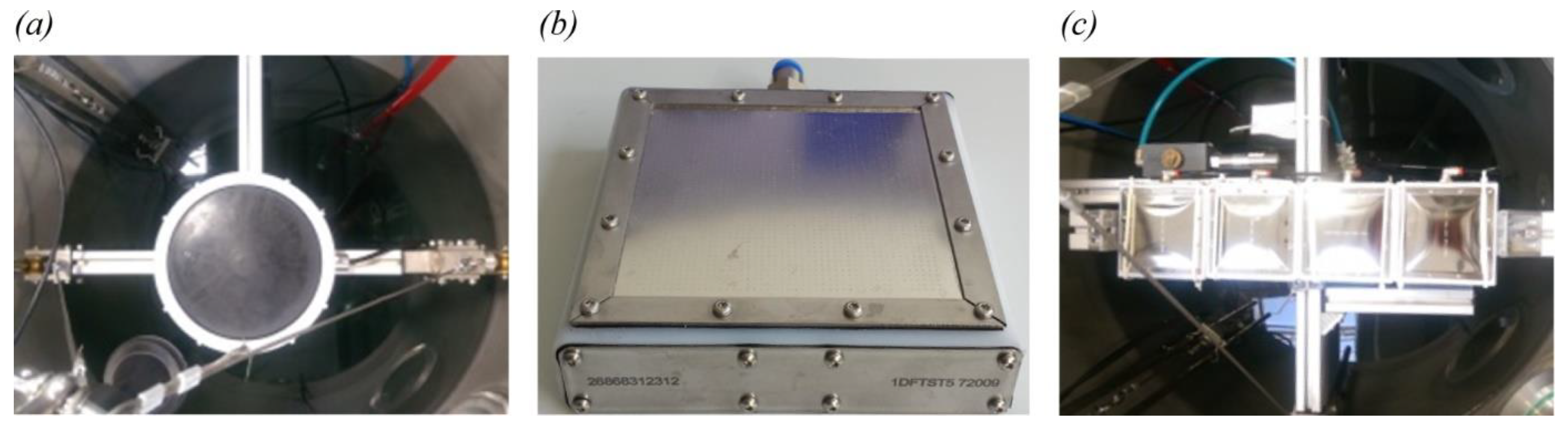
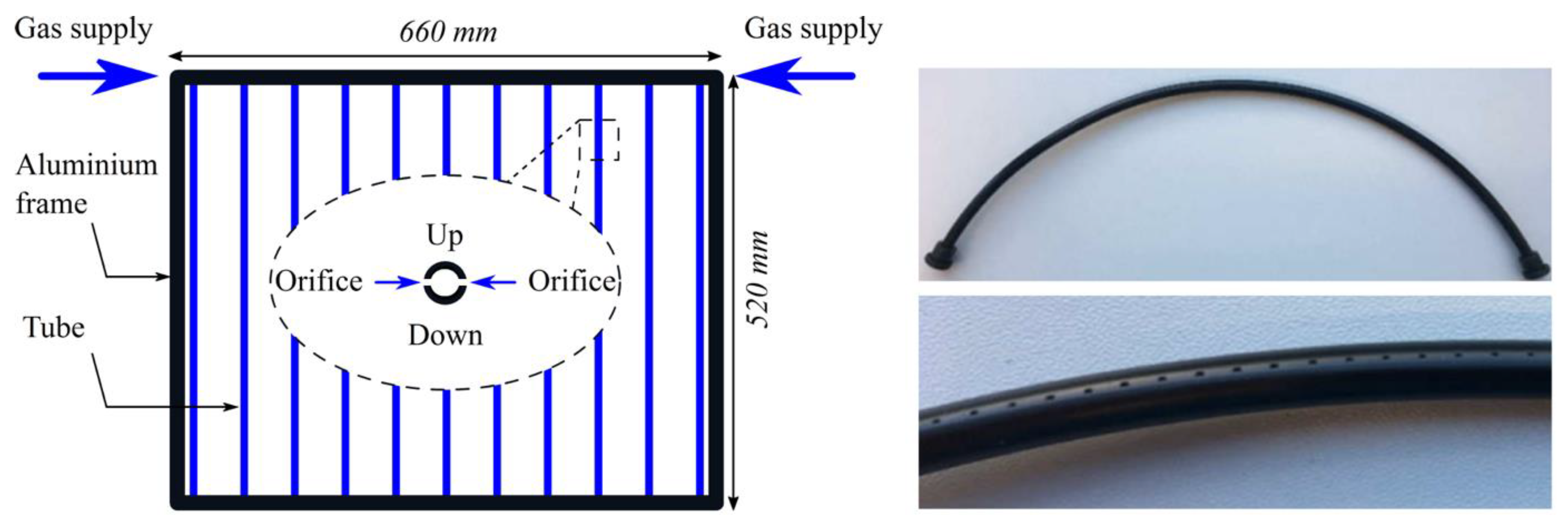
2.1. Bubble Size Measurement

The bubble size investigation was conducted in an acrylic glass column with a cross-section of 400 mm × 400 mm and 300 mm height filled with deionized water. Bubble size from various diffusers was measured using videometry with a backlight technique. To avoid overlapping of bubbles, one row of orifices per diffuser was operated in isolation. A high-speed camera from Vision Research, Inc. model VEO 710L was used together with a microscope lens, Model K2 DistaMaxTM from Infinity Photo-Optical Company. The optical system has a spatial resolution as small as 2 µm/pix and a temporal resolution as small as 25 µs, and the exposure time was set to 8 μs. The backlight was supplied by a 200 W pulsed LED light source from Veritas light model constellation 120E. The final bubble volume was determined using a proprietary image processing algorithm developed by Ziegenhein [16]. A detailed explanation of each step is provided in Mohseni et al. [15]. Eventually, the Sauter mean diameter d 32 , also known as the surface-volume mean, was reported as the representative mean value of the bubble diameter.

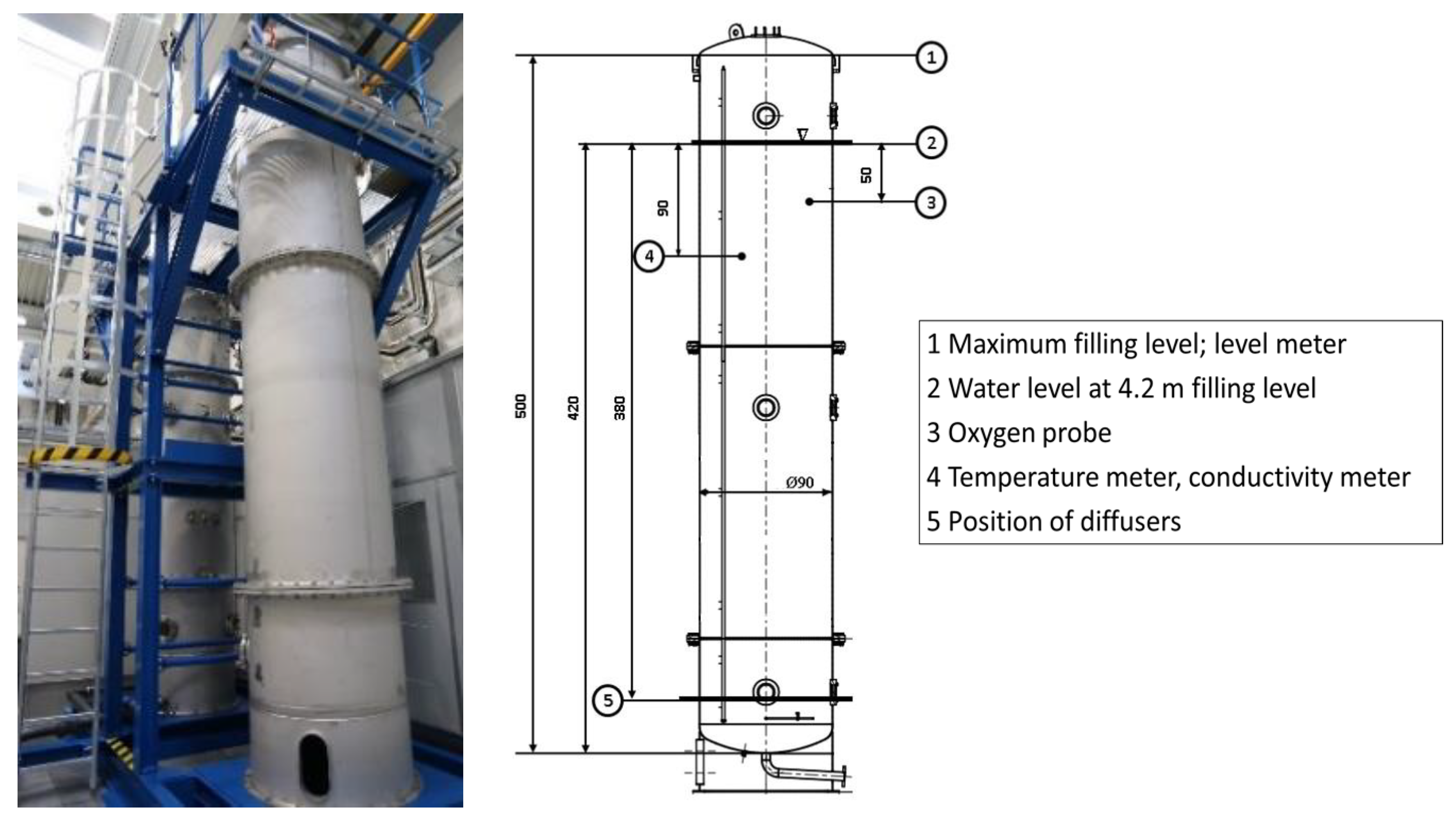
2.2. Experimental Setup for Oxygen Transfer

Oxygen absorption experiments for various diffuser types were performed in a pilot-scale test facility. The facility comprises two instrumented activated sludge bubble columns that have a maximum aeration depth of 4 m and an inner diameter of 900 mm (see Figure 1). Deionized water (σ < 10 µS/cm) was used as a reference in the absorption experiments. The airflow was controlled using mass flow controllers (up to 250 slpm, standard conditions: 1.01325 bar at 25 °C) from Omega Engineering Inc. The range of the volumetric air flow rate was kept between 1 m3·h−1 and 7 m3·h−1 for clean water. For the investigation of the oxygen absorption, the columns were equipped with dissolved oxygen sensors. A submersible relative pressure sensor measured the pressure drop in the gas feed line upstream of the diffusers.
The aeration efficiency of the micro-perforated plate and tube diffusers were compared with commercially available diffusers in wastewater treatment plants with disc, tube and plate shapes. The diffusers were tested under the same conditions while placed at the bottom of the DN 900 columns. Table 1 provides the characteristics of the studied diffusers. The micro-perforated plate diffusers were manufactured using a laser drilling technique. A single micro-perforated plate diffuser had an active aeration area of 0.01 m2. To achieve an active aeration area comparable to the one from commercial diffusers, a set of four micro-perforated plate diffusers with the same orifice diameters were installed together in the columns (see Figure 2).
The micro-perforated tube diffuser had an orifice diameter of 50 µm. The tubes were made out of polyamide. A laser drilling technique was used for manufacturing the orifices of the tubes. Figure 3 shows a scheme and a close-up picture of this tube diffuser concept. Moreover, the tube diffuser provides a more homogenous cross-sectional distribution of the gas phase in favor of limited bubble coalescence when compared to other diffusers while maintaining a high orifice density. The tubes were installed within a frame for the tests in the experimental facility (see Figure 3). In the latter, each tube was sealed from one side while there was a gas feed from the other side. The lateral surface of the cylindrical-shaped tubes embodied the active aeration area for one micro-perforated tube. Including twelve micro-perforated tubes, the diffuser had an active aeration area of 0.104 m2, which is similar to commercial diffusers.

2.3. Oxygen Mass Transfer Measurement

Oxygen transfer was measured in clean water using an absorption measurement technique, and the specific parameters were calculated with Equations (1)–(5) according to DWA-M 209 [17]. The measurements were conducted as batch experiments based on the non-steady-state mode. First, nitrogen gas was supplied for the removal of oxygen from the liquid phase. Subsequently, re-oxygenation with air at a certain flow rate was provided until the oxygen saturation concentration in the liquid phase (CS,p*,T) was reached. The dissolved oxygen concentration was monitored with an oxygen sensor during the whole process.
The temporal oxygen concentration Ct can be expressed with
C t = C S , p * , T ( C S , p * , T C 0 ) · e k L a T · t   [ mg / L ]
with the volumetric mass transfer coefficient kLaT, the dissolved oxygen saturation concentration CS,p*,T for the experimental conditions and the initial dissolved oxygen concentration C0. Based on the measured values of C0 and CS,p*,T, kLaT was determined using (1) as a nonlinear regression model.
The determined kLaT and CS,p*,T values had to be adjusted to standard conditions in the following way:
k L a 20 = k L a T · 1.024 ( 20 T )   [ h 1 ]
C S , 20 = C S , p * , T · C S , St , 20 C S , St , T · 1013 p *   [ mg / L ]
in order to enable a comparison of different experimental conditions. SOTR was calculated from kLa20, and the tank volume (V) was calculated according to
SOTR = V · k L a 20 · C S , 20 1000   [ kg / h ]
SOTR was then used to compare the oxygen transfer of various diffusers over a wide range of volumetric gas flow rates. SAE was used for comparison in terms of power efficiency since it shows how much power input is necessary to dissolve 1 kg of oxygen in water. This measurement considers the required electrical power and was calculated with
SAE = SOTR P   [ kg / kWh ]
The experimental setup was connected to the in-house pressurized air supply. Therefore, it was necessary to calculate the equivalent power (P) that would be needed for the air compression at the specific flow rates.
In this case, P was acquired using
P = Q L , St · E 0 · ( h D + Δ p 98.07 ) Υ   [ kWh ]
from Pöpel and Wagner and Pöpel et al. [18,19]. The equations were derived from manufactures’ data for three different blower and compressor types. For the experimental conditions in this study, we used the positive displacement blower. Hence, a specific energy E0 of 4.3 (Wh·m−3·m) and an exponent Υ = 1 were used.

3. Results and Discussion

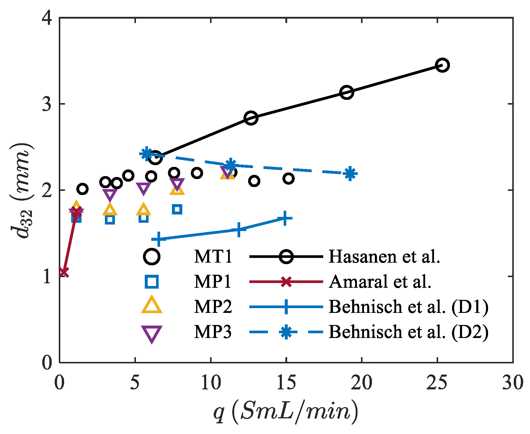
3.1. Bubble Size Measurements

Figure 4 illustrates the trend of d32 with regard to the volumetric gas flow rate per opening (q) from the diffusers in this study and the available data from the literature. Among our own data, MT1 generates the largest bubbles with a slight increase in d32 with q. This is followed by MP3–MP1, which show a similar trend to that of MT1. Although the orifice diameter of MP3 is bigger than that of MT1, the latter generates larger bubbles. A plausible reason behind this observation may be the difference in the surface wettability of polyamide pipes and stainless steel diffusers, orifice orientation and the deformation in the geometry of the orifices during the laser drilling process. Among the data from the literature, the diffusers used by Amaral et al. [10] and Behnisch et al. (D2) [11] generate the smallest bubbles. It should be noted that the range of volumetric gas flow rate per orifice q used by Amaral et al. is below the smallest one in this study [10]. Moreover, Behnisch et al. only measured the bubbles from the side of the spargers to avoid the overlapping of bubbles [11]. The values reported by Hasanen et al. were measured using a suction probe at several points across the diffuser [9].

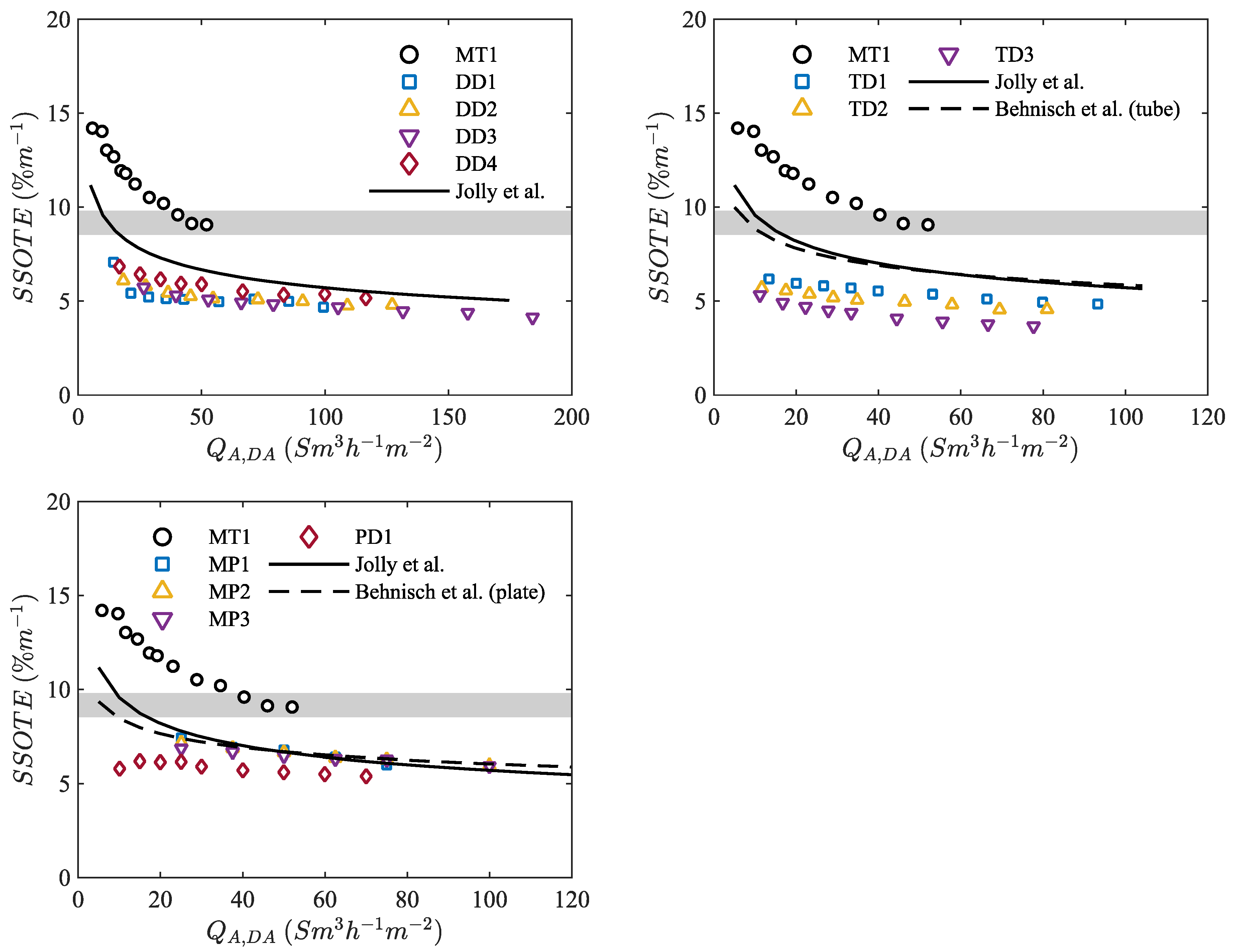
3.2. Oxygen Transfer Efficiency

Figure 5 shows the results of SSOTE as a function of air flow rate per diffuser area of disc diffusers (QA,DA) as well as the correlation for the disc diffusers derived by Jolly et al. [13]. According to DWA, this study covers the typical QA,DA operational ranges of 35 Sm3·h−1·m−2–150 Sm3·h−1·m−2 for disc diffusers and 5 Sm3·h−1·m−2–60 Sm3·h−1·m−2 for plate diffusers [20]. The results for the standard disc diffusers from this study are in good agreement with those of Jolly et al. [13]. However, the micro-perforated tube diffuser (MT1) accomplishes more than 14%·m−1 SSOTE at the lowest QA,DA and 9%·m−1 at the highest QA,DA. For the best SSOTE of the disc diffuser DD1 with 7% m−1 for the lowest QA,DA and 5%·m−1 for the highest QA,DA (DD4), the MT1 outperforms these values by 50% and 44%, respectively. Taking into account the literature findings of Jolly et al., this represents an enhancement in the SSOTE of 20% at the highest QA,DA and an improvement of 33% for the lowest QA,DA of MT1 [13].
According to Figure 5, MT1 exceeds the SSOTE of the membrane tube diffusers for all measured flow rates. For the lowest flow rate, MT1 exceeds the SSOTE of 6.18%·m−1 from TD1 by more than 55%. For the highest QA,DA, MT1 shows an improvement in the SSOTE of more than 46% compared to the 4.85%·m−1 of TD1. Regarding SSOTE, the diffusers MP1–3 are in good agreement with the values reported by Behnisch et al. and Jolly et al. [13,14]. The SSOTE values of MP1–3 are slightly above those of PD1. With 7.40%·m−1 at the lowest QA,DA, the SSOTE of MP1 is 20% better compared to the SSOTE of PD1.
MT1 shows improvements for all QA,DA compared to all other diffusers. This is believed to be due to the generated bubble size, which results in a better mass transfer and, therefore, better oxygen transfer efficiency. With a reduction in bubble size, the partial pressure of the dissolved gas component increases, and the gas dissolves easier. This partial pressure is the driving force for the gas dissolution. Moreover, smaller bubbles have a lower bubble rising velocity and, therefore, a higher residence time. Among the studied diffusers, only MT1 exceeds the favorable SSOTE range of 8.5%·m−1–9.8%·m−1, especially for QA,DA < 35 Sm3·h−1·m−2 [14].
It should be noted that this evaluation does not include the effect of diffuser density. A higher diffuser density enhances SSOTE, especially for low gas flow rates [14]. Thus, the recommended range of SSOTE by Behnisch et al. can be reached with a higher number of membrane diffusers [14].
MP1–3 achieve SSOTE values comparable to those of the tested plate diffuser PD1, although no enhancement in mass transfer is observed. Nevertheless, the SSOTE of the micro-perforated plate diffuser is better than that of PD with less than one-half of the diffuser surface area and a lower number of orifices and orifice density, respectively. A lower orifice density means a wider distance between the orifices and, thereby, a more homogenous cross-sectional bubble distribution [7]. Therefore, bubbles will remain smaller because of less bubble coalescence and, consequently, preserve their small size. Moreover, a wider bubble distribution provides a more homogenous gas concentration gradient across the column. This avoids local degradation in the concentration gradients due to the creation of bubble plume. Because of the low orifice density and due to the novel shape, MT1 has a more homogenous spatial bubble distribution compared to other diffusers, including the micro-perforated plate diffusers. We observed that MT1 reaches oxygen saturation in the liquid phase quicker than all other tested diffusers. This is important in terms of gas transfer efficiency with respect to the same gas flow rates for all tested diffusers.

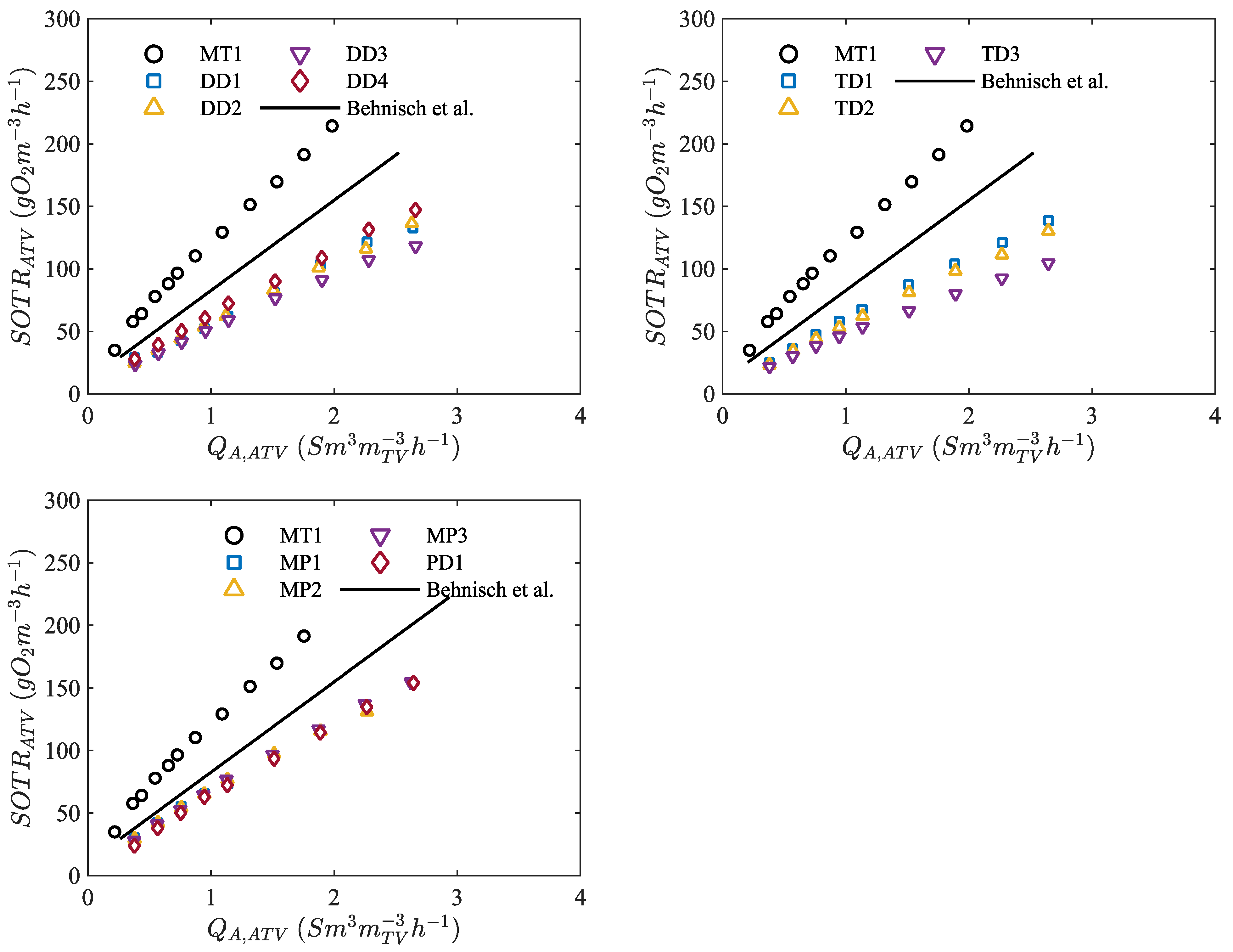
3.3. Oxygen Transfer Rate

Figure 6 depicts the variation in SOTR per aerated tank volume, SOTRATV, as a function of air flow rate per aerated tank volume, QA,ATV, for the various diffusers. The investigated disc diffusers achieved similar SOTRATV values, and the results show a good linear correlation as well as an agreement with Behnisch et al. [14]. MT1 achieved SOTRATV   130 gO2·m−3·h−1 with a QA,ATV =1.1 Sm3·mtv−3·h−1, whereas all tested disc diffusers needed more than 2.20 Sm3mtv−3h−1 to reach a comparable SOTRATV. For the given experimental facility, this would represent an improvement in the QA,ATV of about 50%. According to Behnisch et al., a QA,ATV of 1.65 Sm3·mtv−3·h−1 would be necessary to have an SOTRATV of 130 gO2·m−3·h−1 [14]. Compared to the value of MT1, this would still be an improvement of 33% for the required QA;ATV. Moreover, to reach a favorable SOTRATV of 120 gO2 m−3h−1 over peak loads, a QA,ATV of 0.97 Sm3·mtv−3·h−1 is needed for MT1. This number is 35% below the suggested value of 1.50 Sm3·mtv−3·h−1 [14].
The tube diffusers have a comparable SOTRATV, and the results are in agreement with the literature and illustrate a linear correlation. For an SOTRATV of about 130 gO2·m−3·h−1, TD1 and MT1 need QA,ATV = 2.65 Sm3·mTV−3·h−1 and QA,ATV = 1.10 Sm3·mTV−3·h−1, respectively. This is an enhancement of nearly 60% for MT1 compared to TD1 in terms of QA,ATV. Moreover, the SOTRATV values of MP1–3 do not have a wide distribution. PD1 and MP1–3 would reach an SOTRATV of 120 gO2·m−3·h−1 over peak loads with QA,ATV     1.95 Sm3·mTV−3·h−1. The latter is 50% more than the QA,ATV for the same SOTRATV of MT1. For SOTRATV = 130 gO2·m−3·h−1, PD1 and MP1–3 require QA,ATV     2.10 Sm3mtv−3h−1, where MT1 achieves a similar SOTRATV with QA,ATV   1.008 Sm3·mtv−3·h−1.
Based on the observations of SOTRATV, the calculation of SSOTE is possible. In this case, the micro-perforated diffusers accomplish better results compared to the membrane diffusers. Moreover, the micro-perforated diffusers could surpass the recommended SOTRATV of 120 gO2·m−3·h−1 [14]. The reason is a homogenous cross-sectional bubble distribution and, consequently, less bubble coalescence as well as the generation of small bubbles. Accordingly, kLa improves and, as a result, SOTR improves with it.

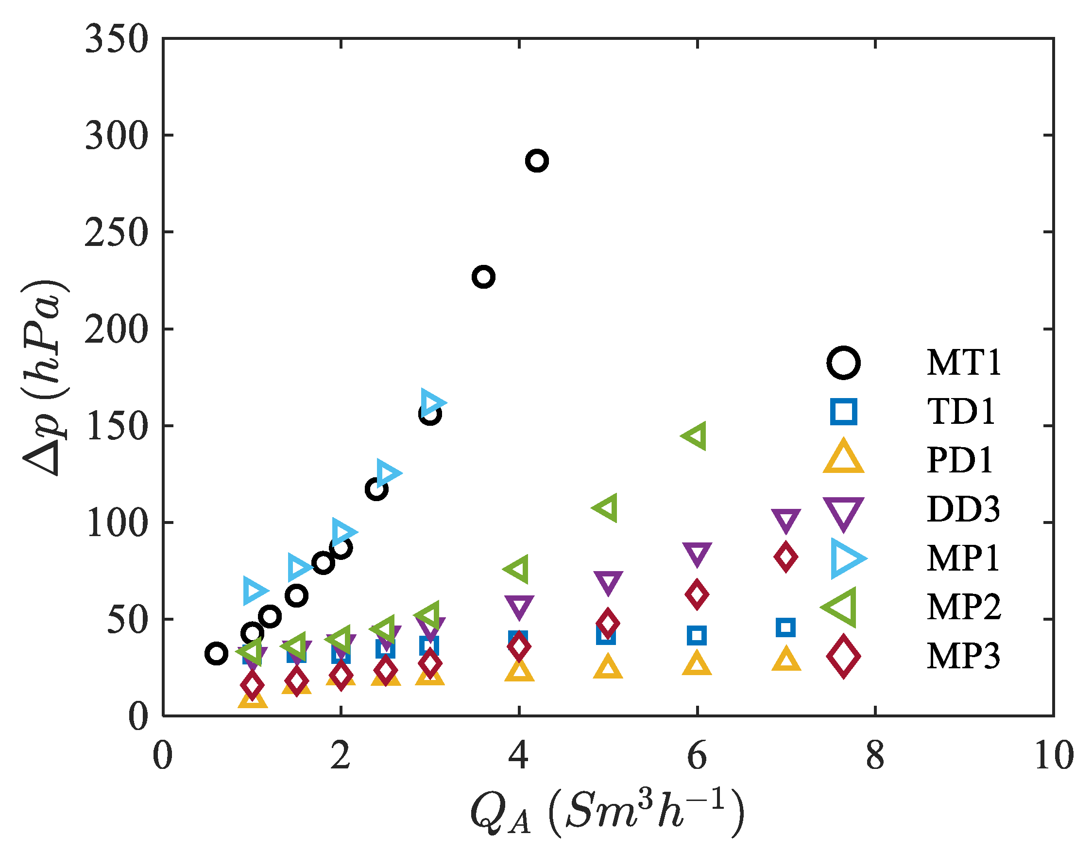
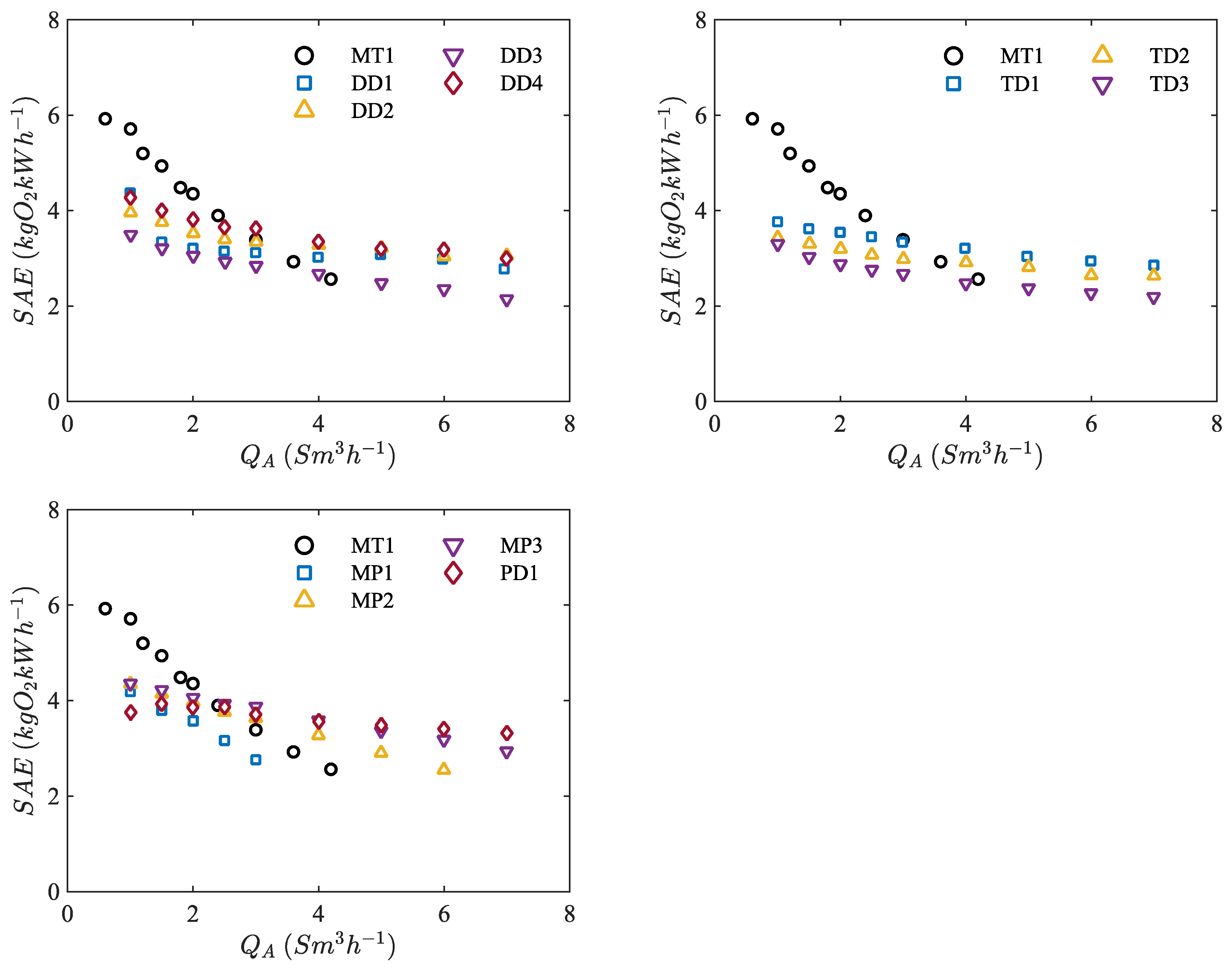
3.4. Pressure Loss and Aeration Efficiency

Figure 7 shows the pressure drop Δp of different types of diffusers. Since the Δp of diffusers from the same category is similar, one diffuser from each diffuser group is presented in Figure 7. Clearly, there is a difference in Δp values between the chosen disc, tube and the plate diffusers compared to MT1 and MP1. For MT1 and MP1, Δp at QA = 1 Sm3·h−1 are 43 hPa and 65 hPa, respectively. However, PD1 and TD1 have a Δp of 28 hPa and 46 hPa at QA = 7 Sm3h−1. The maximum Δp among all diffusers is recorded for MT1 at QA = 4.2 Sm3·h−1 with a value of 286 hPa. Regarding MP3 and DD3, both diffusers show a comparable Δp. From Figure 7, it can be concluded that the orifice size and total orifice number have a significant effect on Δp. For similar QA, less orifices have to cope with the same gas volume. Therefore, the volumetric gas flow rate from these orifices has to increase, which causes more flow resistance and eventually an increase in Δp. MP1 has the smallest orifices among the other diffusers but, in total, more orifices than MP2 and MP3. However, the total orifice surface area of MP1, i.e., AT,O = 8.2 mm2, is less than the total orifice surface area of MP2, i.e., AT,O = 11.8 mm2, and MP3, i.e., AT,O = 20 mm2. Consequently, Δp decreases with the change from MP1 to MP3. Moreover, this would explain the greater increase in the Δp of DD3 due to the smaller total surface area of the orifices compared to the other tested disc diffusers. This is also true when comparing the Δp of DD3 to the other plate and tube diffusers. Similarly, the high Δp of MT1 is related to the low AT,O. MT1 has the lowest AT,O = 7.2 mm2 among all the investigated diffusers.
Figure 8 presents the results of SAE. It shows that MT1 has a sharp decrease in SAE by increasing QA compared to the other diffusers. For QA = 1 Sm3·h−1, MT1 achieved SAE 5.70 kgO2·kWh−1. For a similar QA, the values of SAE for DD4 and DD1 are 4.40 kgO2·kWh−1 and 4.30 kgO2·kWh−1. Comparing MT1, DD4 and DD1, the SAE of MT1 exceeds the other diffusers by 23% and 25%, respectively. However, by further increasing QA, the SAE of MT1 drops below the results of DD1, DD2 and DD4. For QA = 4.20 Sm3h−1, MT1 achieves an SAE of 2.56 kgO2·kWh−1, while DD3 reaches an SAE of 2.67 kgO2·kWh−1.
In the case of tube diffusers, MT1 has a higher SAE value compared to the tube diffusers for QA ≤ 3 Sm3·h−1. Moreover, MT1 reaches a better SAE for QA ≤ 2.4 Sm3·h−1 compared to PD1 and the MP(s). PD1 and MP3 reach a similar SAE of 4.35 kgO2·kWh−1 for a QA of 1.0 Sm3·h−1. In general, MT1 shows the best results for SAE in the air flow rate range of 0.6 Sm3·h−1 to 2.4 Sm3·h−1. MP1–3 attain a similar SAE compared to the investigated conventional plate diffuser.
All investigated membrane diffusers in Figure 8 have a decreasing trend for SAE with an increase in QA. As previously explained, the micro-orifices lead to a higher Δp over an increasing QA compared to the membrane diffusers. Since SAE is calculated as the ratio of SOTRATV to P and Δp, the decrease in the SAE of MT1, MP1 and MP2 is mostly attributed to the Δp. Moreover, since SOTR does not decrease with QA, Δp remains as the major influencing parameter for the decrease in SAE. One way to address this issue could be to increment the number of micro-perforated tubes and plates per m2 coverage area. This would increase the number of orifices, resulting in a lower flow rate per orifice that leads to a lower Δp due to an enhanced AT,O.

4. Conclusions and Outlook

We studied the performance of micro-perforated diffusers with regard to oxygen transfer and compared them with commercially available membrane diffusers. Our assessments included various parameters, such as kLa, SOTR and SAE, in clean water with an aeration depth of 4 m in an instrumented pilot-scale test facility. Furthermore, we compared our results with the literature. The following conclusions can be drawn from our investigation:
  • Micro-perforated diffusers are able to deliver bubbles with d 32 2 . In this case, the micro-perforated plate diffusers are able to generate smaller bubbles than those of the micro-perforated tube diffuser.
    Regarding the results of the SSOTE, the micro-perforated tube diffuser outperforms the membrane diffusers with up to 50% and 44% higher SSOTE for the lowest flow rate and the highest flow rates, respectively. Additionally, the micro-perforated small tube diffuser surpasses the referenced trend lines by at least 20% and reaches the recommended SSOTE range of 8.5%·m−1–9.8%·m−1.
  • In the case of SOTRATV, the micro-perforated tube diffuser achieves 48% diminution in QA,ATV compared to the best accomplished results of the membrane aeration elements. In addition, the novel tube system results in a reduction of the QA,ATV of 33% and 35% compared to the literature trend line.
  • The reasons behind the good performance of the micro-perforated tube diffuser are believed to be the fine bubble aeration, with bubble sizes as small as 1.8 mm, and the homogenous spatial bubble distribution.
  • The novel tube system results in an improved SAE of up to 20% for QA ≤ 2.4 Sm3·h−1. However, increasing QA results in a decrease in SAE. The latter is shown to be mainly due to the enhanced Δp as QA increases. The resultant SAE of the micro-perforated plate diffusers with 50 µm and 70 µm orifices corresponds to the outcomes of the membrane plate diffuser, although Δp for the micro-perforated plate diffusers is higher than the Δp of the membrane plate diffuser.
Based on the current findings, we suggest QA ≤ 3.0 Sm3·h−1 as a preferred working range for micro-perforated tube and plate diffusers. Within this range, micro-perforated diffusers are able to achieve the required oxygen demand of 120 gO2·m−3·h−1 with a lower or equal flow rate in comparison with state-of-the-art membrane diffusers. Moreover, we propose a more homogenous cross-sectional bubble distribution instead of a centered aeration surface. A better aeration efficiency due to a small bubble production and a wider bubble distribution would decrease the air consumption in the aeration process and, therefore, reduce the required power supply of the air blowers because of an improved gas transfer. Nevertheless, novel diffuser concepts with micro-perforated orifices should be investigated in experiments with wastewater to assess the effect of biofouling, the resilience of the material and the impact on the aeration efficiency. Further, different diffuser densities and, for the novel tube system, more tubes should be examined to investigate the effects on pressure loss.

Author Contributions

Conceptualization, R.H.-H. and S.F.R.; methodology, R.H.-H. and S.F.R.; formal analysis, R.H.-H., F.R., E.M. and S.F.R.; investigation, R.H.-H., F.R. and E.M.; data curation, R.H.-H., F.R. and E.M.; writing—original draft preparation, R.H.-H.; writing—review and editing, R.H.-H., F.R., E.M. and S.F.R.; visualization, E.M.; supervision, S.F.R. and U.H.; project administration, S.F.R. and U.H.; funding acquisition, S.F.R. and U.H. All authors have read and agreed to the published version of the manuscript.

Funding

This work is partly funded by the Initiative and Networking Fund of the Helmholtz Association in the frame of the Clean Water Technology Lab CLEWATEC—a Helmholtz Innovation Lab. This work is partly funded by the European Social Fund and the Free State of Saxony, reference number: 100284305. Results for diffusers PD1, DD1-4, TB1-3 and MP1-3 originate from the project SEBAK, which was funded by the Ministry for Climate Protection, Environment, Agriculture, Conservation and Consumer Protection of the State of North Rhine-Westphalia (MULNV, LANUV NRW; reference number: 17-04.02.01-9a/2014). The results for diffuser MT1 originate from the research project LEOBEL, which was funded by the German Federal Environmental Foundation (DBU—Deutsche Bundesstiftung Umwelt; reference number: AZ30799).

Institutional Review Board Statement

Not applicable.

Informed Consent Statement

Not applicable.

Acknowledgments

IWEB GmbH (Bochum, Germany) provided the samples of the micro-perforated diffusers.

Conflicts of Interest

The authors declare no conflict of interest.

Nomenclature

APerforated Diffuser Aream2
C0Dissolved oxygen concentration at t = 0kg/m3
CS,20Oxygen saturation concentration at T = 20 °C and p = 1013 hPakg/m3
CS,St,20Oxygen saturation concentration from EN 25814, CS,St,20 = 9.09 mg/Lkg/m3
CS,p*,TOxygen saturation concentration at T and p*kg/m3
CtDissolved oxygen concentration at time tkg/m3
dColumn diameterm
d32Sauter mean diameter mm
DD#Disc-shaped diffuser-
E0Specific energy of blower/compressorWh/(m3m)
hColumn heightm
hDAeration depthm
kLaVolumetric mass transfer coefficient1/s
kLa20Volumetric mass transfer coefficient at 20 °C1/s
kLaTVolumetric mass transfer coefficient at T1/s
MP#Micro-perforated stainless steel diffuser-
ΔpPressure drophPa
p*Atmospheric pressurehPa
PPowerkWh
PD#Plate-shaped diffuser-
qVolumetric gas flow rate per orificem3/s
QAGas flow rate for standard conditionsSm3/s
QA;ATVGas flow rate per aerated tank volume area for standard conditionsSm3/(m3TVh)
QA,DAGas flow rate per diffuser area for standard conditionsSm3/(m2h)
SAEStandard aeration efficiency kg/kWh
SSOTESpecific standard oxygen transfer efficiency%/m
SOTRStandard oxygen transfer ratekg/h
SOTRATVStandard oxygen transfer rate per tank volumeKg/(m3TVh)
TTemperature°C
TD#Tube-shaped diffuser-
VFilled column volume (tank volume)m3/m3TV
σElectrical conductivityµS/cm
ΥExponent for blower type-

References

  1. Masłoń, A.; Czarnota, J.; Szaja, A.; Szulżyk-Cieplak, J.; Łagód, G. The Enhancement of Energy Efficiency in a Wastewater Treatment Plant through Sustainable Biogas Use: Case Study from Poland. Energies 2020, 13, 6056. [Google Scholar] [CrossRef]
  2. Metcalf, L.; Eddy, H.P.; Tchobanoglous, G. Wastewater Engineering: Treatment, Disposal, and Reuse; McGraw-Hill New York: New York, NY, USA, 1991; Volume 4. [Google Scholar]
  3. Motarjemi, M.; Jameson, G. Mass transfer from very small bubbles—The optimum bubble size for aeration. Chem. Eng. Sci. 1978, 33, 1415–1423. [Google Scholar] [CrossRef]
  4. Kantarci, N.; Borak, F.; Ulgen, K.O. Bubble column reactors. Process Biochem. 2005, 40, 2263–2283. [Google Scholar] [CrossRef]
  5. Jin, B.; Yin, P.; Lant, P. Hydrodynamics and mass transfer coefficient in three-phase air-lift reactors containing activated sludge. Chem. Eng. Process. Process Intensif. 2006, 45, 608–617. [Google Scholar] [CrossRef]
  6. Alkhalidi, A.; Amano, R. Bubble Deflector to Enhance Fine Bubble Aeration for Wastewater Treatment in Space Usage. In Proceedings of the 50th AIAA Aerospace Sciences Meeting Including the New Horizons Forum and Aerospace Exposition, Nashville, TN, USA, 9–12 January 2012; p. 999. [Google Scholar]
  7. Alkhalidi, A.A.; Amano, R. Factors affecting fine bubble creation and bubble size for activated sludge. Water Environ. J. 2015, 29, 105–113. [Google Scholar] [CrossRef]
  8. Mohseni, E.; Herrmann-Heber, R.; Reinecke, S.; Hampel, U. Bubble Generation by Micro-Orifices with Application on Activated Sludge Wastewater Treatment. Chem. Eng. Process. Process Intensif. 2019, 143, 107511. [Google Scholar] [CrossRef]
  9. Hasanen, A.; Orivuori, P.; Aittamaa, J. Measurements of local bubble size distributions from various flexible membrane diffusers. Chem. Eng. Process. Process Intensif. 2006, 45, 291–302. [Google Scholar] [CrossRef]
  10. Amaral, A.; Bellandi, G.; Rehman, U.; Neves, R.; Amerlinck, Y.; Nopens, I. Towards improved accuracy in modeling aeration efficiency through understanding bubble size distribution dynamics. Water Res. 2018, 131, 346–355. [Google Scholar] [CrossRef] [PubMed]
  11. Behnisch, J.; Ganzauge, A.; Sander, S.; Herrling, M.; Wagner, M. Improving aeration systems in saline water: Measurement of local bubble size and volumetric mass transfer coefficient of conventional membrane diffusers. Water Sci. Technol. 2018, 78, 860–867. [Google Scholar] [CrossRef]
  12. Wang, L.K.; Shammas, N.K.; Hung, Y.-T. Advanced Biological Treatment Processes: Volume 9; Springer Science & Business Media: Berlin/Heidelberg, Germany, 2010; Volume 9. [Google Scholar]
  13. Jolly, M.; Green, S.; Wallis-Lage, C.; Buchanan, A. Energy saving in activated sludge plants by the use of more efficient fine bubble diffusers. Water Environ. J. 2010, 24, 58–64. [Google Scholar] [CrossRef]
  14. Behnisch, J.; Schwarz, M.; Wagner, M. Three decades of oxygen transfer tests in clean water in a pilot scale test tank with fine-bubble diffusers and the resulting conclusions for WWTP operation. Water Pract. Technol. 2020, 15, 910–920. [Google Scholar] [CrossRef]
  15. Mohseni, E.; Kalayathine, J.J.; Reinecke, S.F.; Hampel, U. Dynamics of Bubble Formation at Micro-orifices under Constant Gas Flow Conditions. Int. J. Multiph. Flow 2020, 132, 103407. [Google Scholar] [CrossRef]
  16. Ziegenhein, T. Fluid Dynamics of Bubbly Flows. Ph.D. Thesis, Technische Universität Berlin, Berlin, Germany, 2016. [Google Scholar]
  17. ATV-Merkblatt, M. 209: Messung der Sauerstoffzufuhr von Belüftungseinrichtungen in Belebungsanlagen in Reinwasser und in belebtem Schlamm; Abwassertechnische Vereinigung eV: Hennef, Germany, 1996. [Google Scholar]
  18. Pöpel, H.J.; Wagner, M. Modelling of oxygen transfer in deep diffused-aeration tanks and comparison with full-scale plant data. Water Sci. Technol. 1994, 30, 71. [Google Scholar] [CrossRef]
  19. Pöpel, J.; Wagner, M.; Weidmann, F. Sauerstoffeintrag und–ertrag in tiefen Belebungsbecken. Schr. WAR 1998, 139, 189–197. [Google Scholar]
  20. DWA. Systeme zur Belüftung und Durchmischung von Belebungsanlagen–Teil 1: Planung, Ausschreibung und Ausführung (Advisory Leaflet DWA-M 229-1: Aeration and Mixing in Activated Sludge Plants, Part 1: Planning, Invitation of Tenders and Accomplishment); German Association for Water, Wastewater and Waste: Aachen, Germany, 2017. [Google Scholar]
Figure 1. Test facility for oxygen absorption measurements: (left) photograph of the DN 900 activated sludge columns, (right) dimensions (in cm) and designation of instruments.
Energies 14 07268 g001
Figure 2. Installation of membrane disc diffuser in the DN 900 column (a). Photograph of a micro-perforated plate diffuser (b). Arrangement of plate diffusers in the DN 900 column (c).
Energies 14 07268 g002
Figure 3. Illustration scheme of aluminum frame with micro-perforated tubes (left); micro-perforated tube with length of 500 mm and an outer diameter of 6 mm (top right); close-up view of tube with orifices of 50 µm in diameter (bottom right).
Energies 14 07268 g003
Figure 4. Sauter mean diameter of bubbles from various diffusers at different volumetric gas flow rates per opening (D1 and D2 in Behnisch et al. refer to Diffuser 1 and Diffuser 2 in the reference [11]).
Energies 14 07268 g004
Figure 5. SSOTE versus QA,DA for all tested diffusers and the micro-perforated diffuser together with the findings from the literature and the favorable SSOTE range of 8.5%·m−1–9.8%·m−1 [14].
Energies 14 07268 g005
Figure 6. SOTRATV vs. QA,ATV for the tested diffusers as well as the results of micro-perforated plate and tube diffusers together with the literature [14].
Energies 14 07268 g006
Figure 7. Pressure drop versus standard gas flow rate for various diffusers.
Energies 14 07268 g007
Figure 8. SAE versus QA for the tested disc, tube and plate diffusers as well as the micro-perforated plate (MP) and tube diffuser (MT1).
Energies 14 07268 g008
Table 1. Characteristics of investigated diffusers.
NameMembrane Area MaterialMembrane Surface Area (m2)Outer Diameter (mm)Length of Diffuser
(mm)
Diffuser Width
(mm)
Orifice Number Per DiffuserOrifice Diameter/Slit Length (mm)Effective Orifice Density (cm−2)
PD1TPU0.100-675215930019.30
DD1EPDM0.070350--7100110.14
DD2EPDM0.055278--75001.513.64
DD3EPDM0.038265--5800115.26
DD4EPDM0.060346--8000113.33
TD1EPDM0.07575530-7500110.00
TD2PU0.09065580-9100110.11
TD3EPDM0.09070600-14,3001.515.89
MP1SS0.040-13513529000.037.25
MP2SS0.040-13513515000.053.75
MP3SS0.040-13513513000.073.25
MT1PA0.104-500636720.053.53
Diffuser type: DD1 to DD4 disc diffusers; TD1 to TD3 tube diffusers; PD1 plate diffusers; MP1 to MP3 micro-perforated plate diffusers; MT micro-perforated tube diffuser; A: perforated diffuser area; EPDM = ethylene propylene diene monomer rubber; PU = polyurethane; TPU = thermoplastic polyurethane; SS = stainless steel; PA = polyamide.
Publisher’s Note: MDPI stays neutral with regard to jurisdictional claims in published maps and institutional affiliations.

