1. Introduction
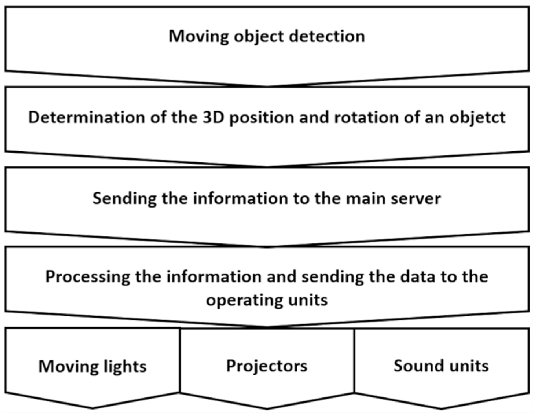
A dynamic lighting system for the stage is based on the interaction of a moving human silhouette or any other object in a scene with a controllable lighting system. This type of lighting system is increasingly used on television, at conferences, during theatrical performances, concerts, shows and other cultural events. Tracking with sound and light, floodlighting the selected parts of any moving object or illuminating the specific spaces on the stage (e.g., floor, walls, props), in real-time, are carried out on the basis of the current position, rotation and direction of the movement of an object. A general diagram of the operation of such a lighting system is shown in
Figure 1.
The dynamic lighting system for the scene is usually equipped with the following elements:
devices for tracking an object in the scene using marks, markers, special dedicated sensors or camera sets,
lighting-projection units: movable luminaires, controllable LED panels, multimedia projectors,
sound equipment.
The key part of the dynamic lighting system is the identification of a moving object in the scene and the precise determination of its position in three-dimensional space. Determining the position of an object in three-dimensional space is possible in three main groups of systems. These systems are the systems with markers [
1,
2,
3,
4,
5,
6], markerless systems [
7,
8,
9,
10,
11,
12] and hybrid systems [
13,
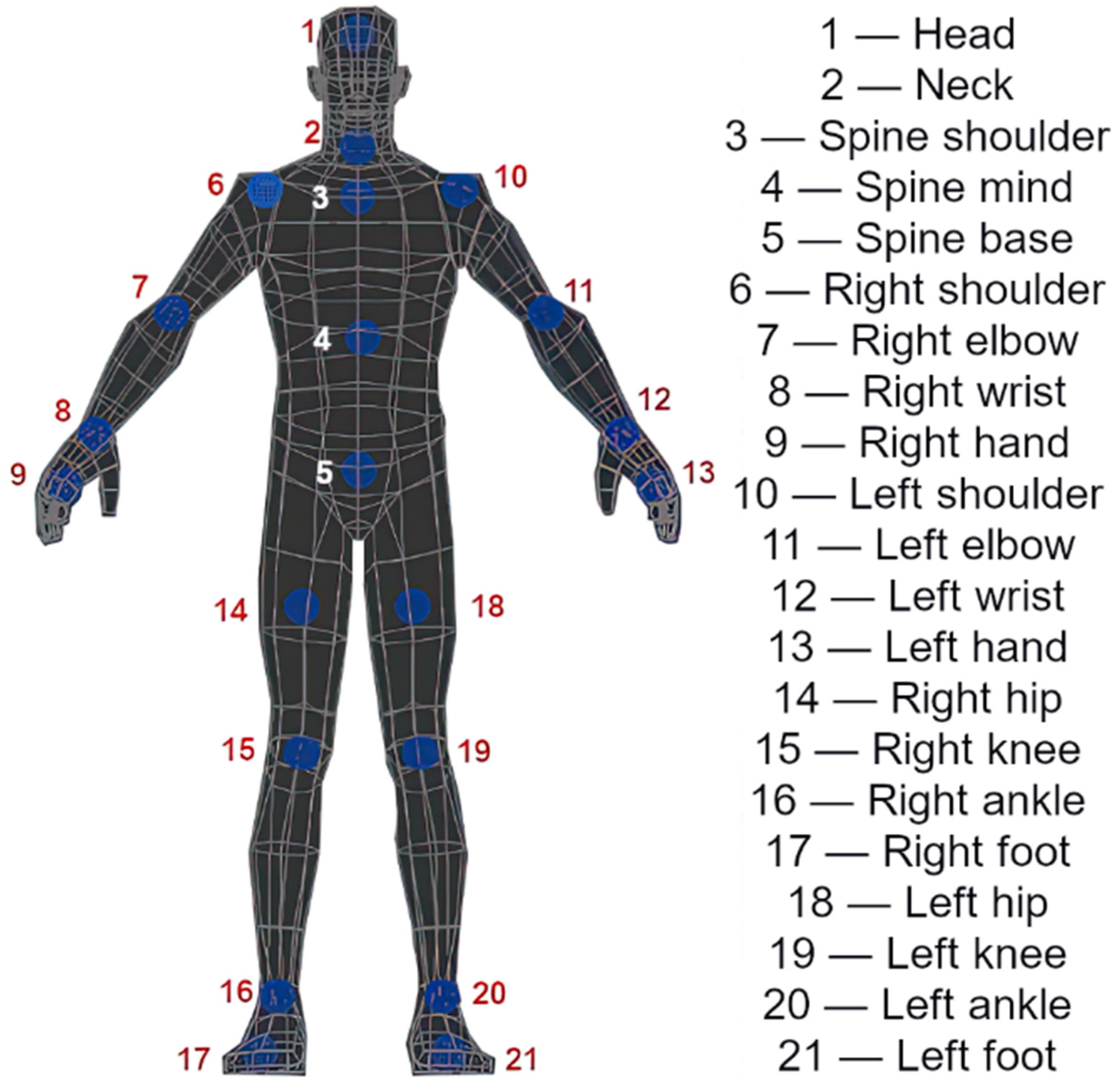
14] that use both markers and digital cameras simultaneously. All the above mentioned identification methods allow the tracking of the moving object. This tracking is based on the information about the 3D coordinates of key points of the tracked object. Therefore, in the silhouette tracking, the skeletal parts reflecting the anatomy of the human body are the characteristic points (
Figure 2). In the case of marker systems, object tracing is based on the use of special markers, such as active or passive markers or clothes that are their components. Markerless identification generally includes the analysis of RGB + IR images or depth maps from cameras recording the scene and algorithms for classifying and identifying moving objects.
In marker systems, it is difficult to maintain high aesthetics while providing high precision of the position and direction identification due to the necessity of using special miniature devices [
1,
3,
4,
5,
6] or clothes [
2] placed on target objects. At the same time, tracing the deformations of flexible surfaces requires the use of a large number of markers or special materials. However, it additionally raises the cost of the system without a significant increase in identification accuracy. Moreover, when it comes to the simultaneous tracking of a large number of objects within the analysed scene, there is a problem of covering the marker, which disrupts the target tracking process. Additionally, the problem of implementing the so-called smart functions is a big limitation of this type of system in relation to lighting. Therefore, some control from a specialist is required in order to adjust the luminance parameters of the light spot and the size of the illuminated area to the changing object dynamically. It is possible to adjust the width of the light beam and make it dependent on the distance of the luminaire from the object. This is possible thanks to mathematical dependencies, taking into account the position of the object in the scene. However, the automatic fitting of the beam width to the objects of different sizes, e.g., a tall or short person, child, animal, is impossible to be performed in a fully automatic and autonomous mode.
Markerless object identification systems use a number of solutions, such as the generation of differential images, in which the background is extracted from the current image in a graphic form. Another solution is the advanced analysis of images obtained from the RGB-D camera system registering the scene. Motion detection and tracking of silhouettes are carried out with the help of the so-called “smart algorithms” that make the correct identification possible in the case of occlusions or the overlapping of many silhouettes. Additionally, markerless identification makes it possible to determine the geometry of the object and its uneven surface. This is important for dynamic projection mapping as it is possible to fit the projection image to the object accurately. The introduction of light from multimedia projectors is an enrichment of the existing systems with regard to dynamic lighting. In this case, the information about the geometry, rotation and position of the object makes it possible to obtain the precise lighting outline that does not extend beyond the contours of the illuminated object. Therefore, in the case of illuminating a moving object, we can illuminate the entire silhouette with the simultaneous masking or limitation of the luminance for the eye zone. Such an illumination enables the discomfort glare elimination or its significant reduction, and in this way, increases the comfort of seeing the audience and an actor alone.
This paper will present the proposal for the implementation methods and basic transformations necessary to perform dynamic mapping or lighting of an object with darkening sensitive zones. The results of experiments related to the study of image transformations and optimisation in order to obtain a stable 30 frames per second using the CPU will be presented and commented on. Additionally, the research connected with the effectiveness of glare reduction will be described by means of limiting the luminance value.
1.1. Object Identification and Dynamic Lighting in Lighting Technology
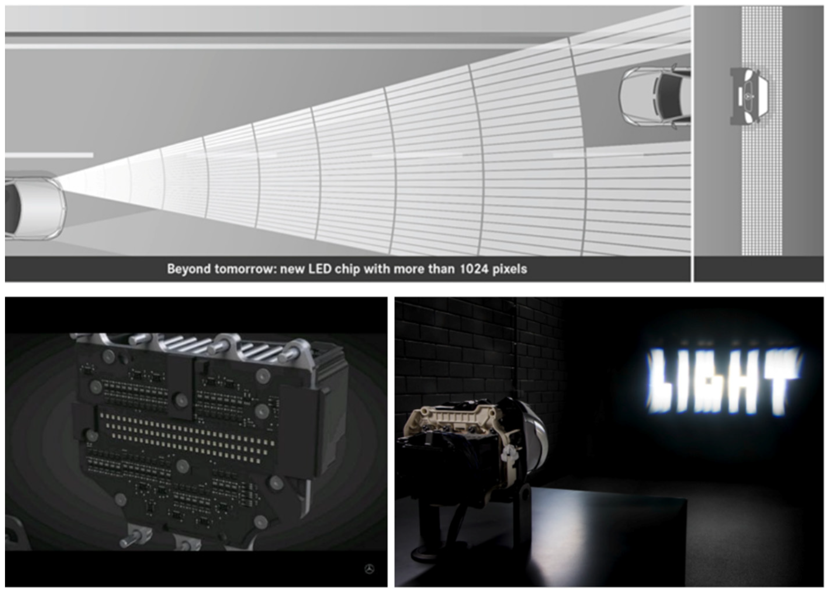
The 21st century is the era of smart devices. However, using the word intelligence is exaggerated in this context as it is the software developer’s intelligence that is behind the smart features of the device. Adaptive instead of intelligent would be a more appropriate term to be used in this context. This term aptly shows that the system, within its specific programmed range, adapts its behaviour or certain parameters to the outdoor conditions. When they tend to change, the behaviour follows them directly. However, the system behaviour and its autonomy still follows the framework programmed by the software developer. All lighting systems that adapt their parameters to the environment require certain assumptions that enable the relatively simple adjustment of their behaviour to specific applications. Adaptive devices used in the modern automotive industry are a good example of such a system. The principle of operation of adaptive car lights consists of supplementing the luminous intensity distribution of traditional passing beam or driving beam [
15,
16] by controlling the LED matrix. In these systems, each LED illuminates a different part of the space in front of the car. The car’s surroundings are monitored with the use of cameras, and the system decides in real-time which part of the road to illuminate and which not (
Figure 3).
Because of its structure and operation mode, the matrix of individually controlled diodes (
Figure 3) begins to resemble the operation of typical multimedia projector systems. Therefore, the technology does not really matter. The LCD, DLP, 3DLP projectors and laser devices set the specific colour and luminance distributions in space in many million points simultaneously. Thus, the concept appeared to use the projector not only in order to implement the projection mapping on any object but also as a device to replace a number of luminaires to illuminate the object [
19]. This paper describes the concept of using professional multimedia projectors to perform basic floodlighting. However, the use of the projector for lighting purposes gives many more possibilities. Such an installation can also be used for coloured lighting and the complete interactive projection mappings. The research proves [
20] that all luminaires with several hundred times of luminous intensity amplification use high-luminance light sources. The luminance values of discharge lamps and LED light sources are within the range of 15 × 10
6–100× 10
6 cd/m
2 [
21,
22]. Such luminance levels may already be dangerous for human eyes, especially when looking towards any luminaires or projectors. Typically, the ambient luminance represents a small fraction of the luminance of the light source and usually does not exceed several dozen cd/m
2 [
19]. Therefore, when adapting the eyesight to darkness, seeing a luminaire or a projector in the field of view causes discomfort and a temporary disturbance of visual acuity, which is called glare [
23].
According to the CIE report (the International Commission on Illumination), glare is a visual condition with excessive contrast or inappropriate distribution of light sources that disturbs the observer or limits the ability to distinguish details and objects [
24]. Glare can be divided into discomfort and disability [
25]. Discomfort glare is that condition of vision that causes discomfort without necessarily impairing the vision of objects [
26]. The most common cause of discomfort glare is a high luminance light source in the observer’s field of view [
25]. High luminance means values above 1 × 10
5 cd/m
2. While disability glare is the condition of vision that impairs the vision of objects without necessarily causing discomfort [
25]. In addition, disability glare does not have to be directly related to the observation of a high luminance value [
25]. The most common cause of disability glare is bright surroundings that cause high levels of illumination in the observer’s eye. The perception of this glare depends on the value of the background luminance from bright sources in the peripheral field of view [
27]. Therefore, if there is a problem with glare on roads illuminated with artificial light, at concerts or in theatres, in the majority of cases, we deal with discomfort glare.
As for the adaptive lighting systems (AFS—Adaptive Front-lighting Systems/IFL—Intelligent Light System/ADB—Adaptive Driving-Beam), these systems are built in such a way as to provide the lighting, similar to the passing beam, with additional illumination of the areas in front of the vehicle similar to the driving beam [
15,
16]. Illuminating the entire vehicle zone will dazzle oncoming drivers. Thus, such a system equipped with a camera or a set of cameras could activate the driving beam in a simple ON/OFF mode only when there is no identification of the vehicle coming from the opposite direction. Today’s systems are much more advanced in terms of design. Therefore, at a lower resolution, i.e., a lower number of dynamically controlled LEDs (
Figure 3), they darken the entire zone beginning in front of the vehicle and covering the oncoming or preceding vehicles. Therefore, at a higher resolution of LED matrices, it is possible to “cut out” the vehicles from the surroundings (
Figure 3) by flooding their contours with some light. This causes glare reduction for drivers and illumination of a much larger part of the road and roadside than when using the passing beam only.
If we turn to the topic of dynamic lighting for the stage or human silhouette mapping, a discomfort glare phenomenon is a very common problem. The previous studies [
20,
28,
29,
30,
31] show that the discomfort glare reduction is a significant problem for the users of the lighting solutions with high-luminance light sources. Therefore, the problem should be discussed, taking into account both the audience watching the lighting effects and the actors or presenters taking part in performances or conferences. The proposed system aims at reducing or eliminating this glare phenomenon. This is possible by masking (darkening) some body parts, such as eyes or heads, in real-time with the help of a projection image. A precisely identified human silhouette and full information about its orientation allow the location of the eye and head area to be calculated with a high accuracy. When it comes to the less complex systems where there are not any matrix lighting projectors, it is also possible to calculate the parameters and control the operation of, e.g., moving luminaires (moving heads), in order to reduce the illumination towards the eyes. However, in this case, this solution is connected with not illuminating the actor’s head, so it excludes this system from the variant where the actor’s head and face should be illuminated. Sometimes this is a desirable approach, e.g., while lighting from the back when the face is illuminated by other luminaires. Nevertheless, the modern systems for the stage lighting using multimedia projectors with brightness’s exceeding 30,000–40,000 ANSI lumens offer almost unlimited possibilities of dynamically shaping the luminance within the illuminated scene.
1.2. Ecology and Ergonomics in Intelligent Lighting of Objects
The direct observation of a high-luminance light source or its image on the surface of an optical system of luminaires is always associated with discomfort. The greater this discomfort is, the bigger the difference in luminance occurring on the surface of the luminaires and in their direct environment is. In this paper, in
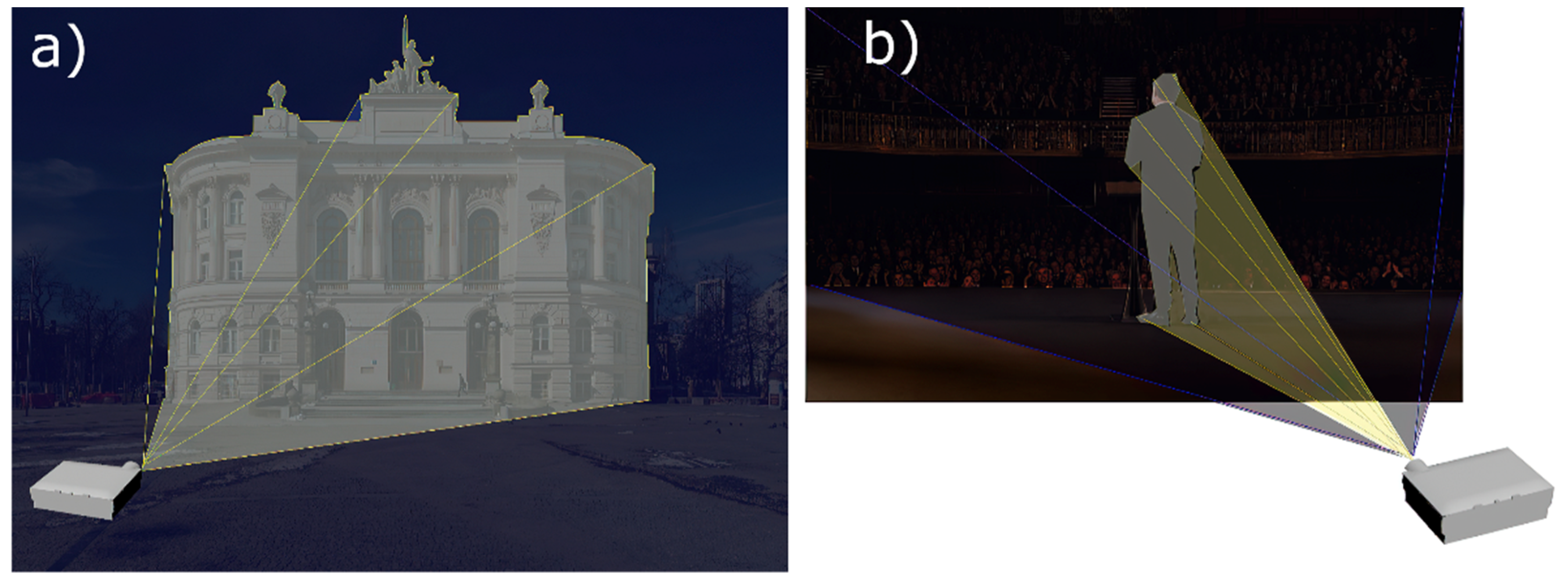
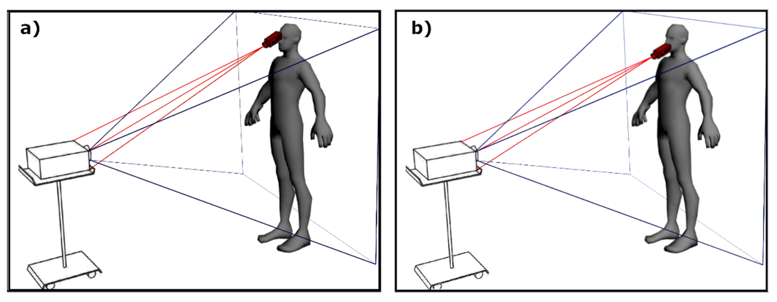
Section 1.1, the potential for reducing the phenomenon of the discomfort glare has been indicated clearly. This can be performed by dynamic darkening or limiting the luminance of sensitive zones using the camera system in order to identify the human silhouette and its temporary spatial orientation. This system is connected to a server and a lighting unit in the form of a multimedia projector. However, the use of a projector or a projector system for lighting purposes has the additional advantage of dynamic masking. In theatres and TV studios, an actor is illuminated from behind by a background light. It is easy to imagine a backlighting system that illuminates the silhouette of an actor facing the audience while masking the audience area actively (
Figure 4b). Thanks to this approach, the audience will not experience discomfort glare (by lack of direct visibility of the luminaires) when the actor’s silhouette and surroundings are fully illuminated. The lighting effect in the form of light reflected from the actor in a Lambertian way will be visible. From the audience’s point of view, the light spot will cover the entire stage, but it will not leave the stage apart from the cases when the lighting specialist wishes to do so (
Figure 4b). Of course, when setting the front lighting, the audience and the actor’s eyes do not have to be completely darkened. In order not to cause a large luminance gradient in the eye area and thus not to distort the image of the illuminated face, the luminance within the sensitive zones can be reduced to such a value that the glare level is acceptable.
The system consisting of a set of cameras, a server and multimedia projectors is a powerful tool that gives almost unlimited possibilities. If necessary, it will enable the individual objects to be illuminated on the stage dynamically and also to map them in real-time. The change of the colour or texture of a garment or items on the stage can be the simplest example of this kind of system (
Figure 5). Dynamic mapping of moving objects on the stage using digital images allows the creation of visual effects that are difficult or even impossible to make with standard stage methods. Bleeding characters, changing the costume appearance without leaving the stage, burning or deforming objects or dynamic modification of their texture, are just some examples of the effects that can be obtained quickly with the help of a dynamic video mapping technique. It is worth mentioning that it is possible to simulate lighting falling on objects from a different direction than it actually falls on. Therefore, in this way, the full illusion of a light source moving around the illuminated object is created. This illusion is obtained by using modelling of the virtual lights and creating the artificial shadow.
In the presented variant of the system, an almost complete elimination of the light pollution problem [
32,
33] is another key feature, apart from the above-discussed discomfort glare reduction and the possibility of “dynamic painting” with light. It is possible to mask the object from its surroundings completely regardless of the illuminated area, whether it will be an object in the interior, a performance in the theatre, a conference speech or even an object illumination. Static objects can be masked statically, taking into account the geometry of the object and the position of the lighting or a mapping projector. However, moving objects, such as vehicles, animals or people, can be illuminated, masked or covered by a graphic luminance map dynamically. This approach causes the effect of cutting the object from the environment and reducing the direct lighting component that does not hit the object. Thus, it is possible to eliminate the luminous flux causing light pollution to the environment or the sky (
Figure 4a).
The ecological aspect of light pollution represents a very important field of lighting technology today. First of all, it is perceived as a significant threat to the natural environment because it can disturb the circadian cycle of animals and plants [
34,
35]. Light pollution also has a negative impact on human health [
34,
35,
36]. It can cause, among others, fatigue, stress, anxiety and decreased immunity, a fall in melatonin productivity or even more serious diseases. An additional problem is the fact that, at the present moment, there are insufficient requirements and regulations concerning this field. Currently, some research aimed at improving the quality and efficiency of object floodlighting while limiting the light pollution phenomenon is being conducted [
32,
37,
38,
39]. Inadequately directed lamps, light sources with too high luminance or operating at a moment when it is unnecessary can be the source of this type of pollution. The use of light from multimedia projectors in dynamic lighting makes it possible to eliminate similar problems completely. It enables the direction of lighting and the luminance level to be controlled, with the possibility of its correction for the sensitive zones and mask the areas that should not be illuminated.
However, as far as a very high precision of dynamic masking is concerned, it is necessary to know the features, position and construction of objects on the stage. In the case of static lighting, it is sufficient to mask the parts of the object precisely and use the masks once registered in the calibration process. When it comes to dynamic lighting, it is necessary to create the smart systems that will be capable of predicting non-standard configurations and positions of objects, such as people. These systems could prepare appropriate masks or colours dynamically and in real-time adaptively and autonomously. As mentioned earlier, in the presented concept, masking is not related to the lighting mode of individual pixels in the ON/OFF mode. For example, in order to minimise discomfort glare while maintaining the high aesthetics of the illuminated objects, the luminance of glaring pixels can be limited to an acceptable level. Local luminance reduction will not be noticed by the observer because it will not be associated with a black spot appearing within a fully illuminated object.
2. System Description
As mentioned earlier, the markerless system is one of the most advanced identification systems. This system is subject to continuous development. However, currently, there are not fully reliable dynamic stage lighting systems based on the RGB-D cameras that can serve a large stage with dimensions close to 20 × 10 m. These systems should be able to identify the position of the object with a high precision. Therefore, the system consisting of many RGB-D cameras and projectors is the target system in the conducted research. The cameras will be used to record the scene and moving objects within its space, and the target projector system will be applied to implement the dynamic lighting with the reduction of such phenomena as discomfort glare or light pollution. Additionally, the system of cameras and projectors will make it possible to “paint” the moving objects in the scene with graphic and multimedia content.
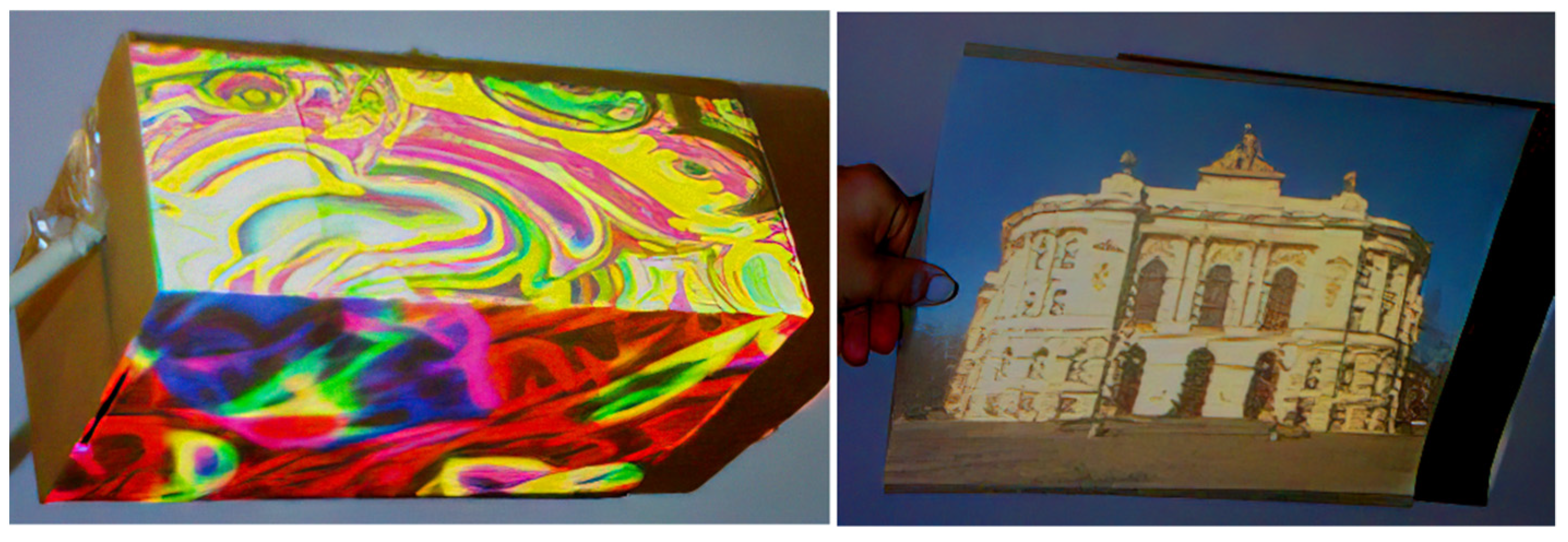
In order to investigate the opportunity to design such a system, some tests were carried out for a single RGB-D camera-projector system in real-time. The result of these tests was the illumination of the surfaces of moving objects, such as a flat sheet of paper, individual walls of a rectangular box [
40] or a silhouette without going beyond the contours (
Figure 6a,b).
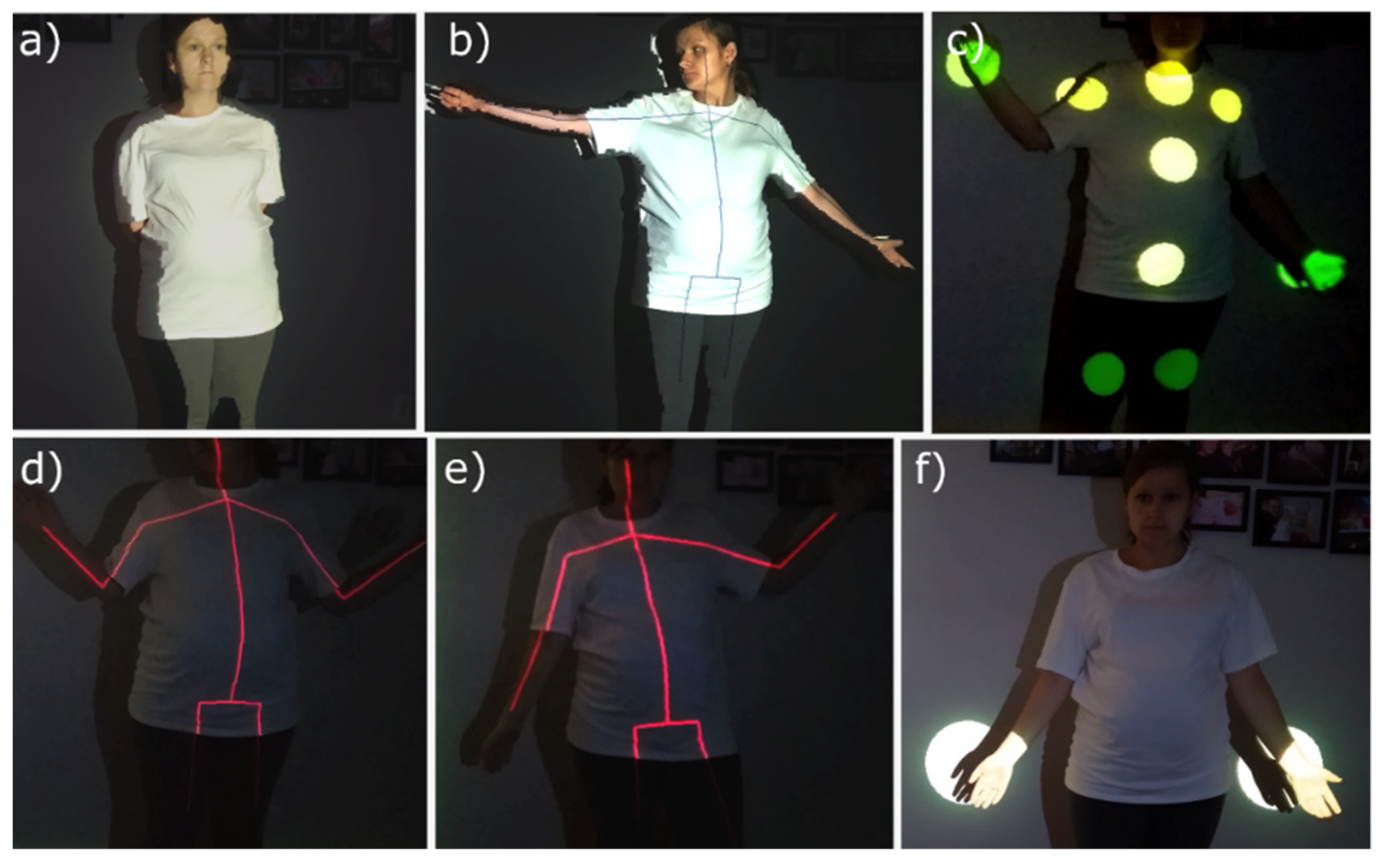
The other test results were the illumination of specific parts of the human body with the possibility of adjusting the light spot and its colour (
Figure 6c,f). The actor’s position in the scene was identified, and the skeleton representing his current pose in real-time was “drawn” (
Figure 6d,e). The identification of individual skeletal parts of the body was also used to darken the sensitive zones, such as the eye area, in order to reduce the discomfort glare phenomenon in the process of dynamic lighting of the human silhouette. Additionally, the images were analysed in terms of the data processing speed in order to determine which parameters had the highest impact on the level of generated delays between the current position of the object and the image displayed on it. The analysis was carried out for both greyscale and colour images. The level of delay translates into the precision of fitting the graphic content to the object. Therefore, the performed research additionally presents the method for optimising the transformation times that play a decisive role in the speed of processing data.
The created system consists of the Kinect v2 RGB-D camera and a FullHD projector. In order to provide the correct video projection, the moving object should move within this space. The RGB-D camera was used to record the scene in the form of depth maps, and the identification of this moving object was performed on its basis. The projector was used to implement dynamic lighting and projection mapping.
Additionally, the dynamic lighting system for a specific part of the human body was designed with the help of a moving head. Such a system includes an RGBD camera and a Cameo CLMHRGB60W moving head [
41]. The control of the luminaire is based on the 8 or 13-channel mode with the possibility of adjusting some parameters, such as: pan (horizontal rotation), tilt (vertical rotation), colour and type of Gobos or dimming. All controllable parameters can take 8-bit values.
The identification of the human body is based on the depth maps recorded by the RGBD camera. The information about the position of the selected skeletal parts is used to direct the lamp and illuminate the specific parts of the body with the light spot in real-time (
Figure 7).
The Labview environment [
42], in which all test algorithms were performed, and the Machine Vision and Image Processing modules [
43] were used to carry out the tests on dynamic projection lighting, mapping on the moving object and lighting with a moving head.
2.1. RGBD Camera-Projector System Calibration
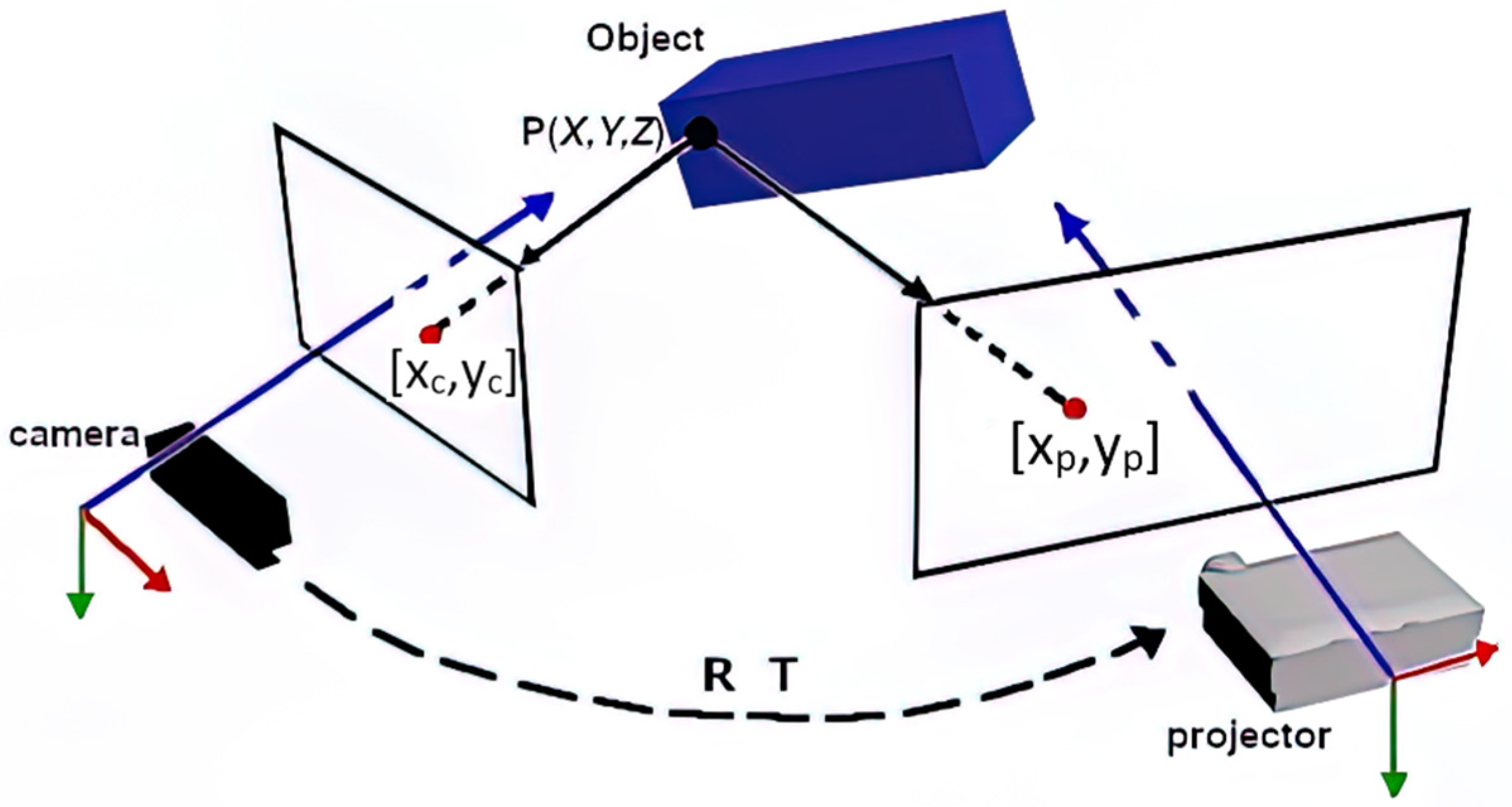
Using the dynamic lighting and projection mapping requires a camera-projector system calibration that has an impact on the accuracy of the object identification in space and the precision of its lighting. The purpose of the system calibration is to find the mathematical dependence between the space recorded by the camera and the space covered by the projector (
Figure 8).
Each point in the space [X, Y and Z] from the camera point of view has the coordinates [X
c, Y
c and Z
c], and the same point in the projector system has the coordinates [X
p, Y
p and Z
p]. The transformation of the transition from one system to another is described by Formula (1):
where R is the rotation matrix of 3 × 3 dimensions and T is the displacement vector of 3 × 1 dimensions.
A pinhole model is used for both camera and projector space. Thus, the creation of a 2D image on the camera matrix is carried out with the use of a perspective view for each point [X
c, Y
c and Z
c] from the 3D space to the corresponding point [
and
] in the camera screen space in accordance with the following dependence:
where w is the scaling factor and [
,
, and
] are the internal parameters of the camera.
Similarly, the transformation of any point from the projector space to the projector screen space is described by Formula (3):
where w is the scaling factor, [
and
] are the coordinates of the point in the projector screen space and [
,
, and
] are the internal parameters of the projector.
It should be added that the RGB-D camera enables the registration of depth maps, i.e., each pixel of the image contains information about the distance from the camera of the recorded point. Thus, the dependence between the coordinates of a point in the 2D image of the camera screen space [
and
] with the additional information about the depth Z
c and the corresponding point in the 2D image of the projector [
and
] is obtained from Formulas (1)–(3):
where w is the scaling factor and [q
1,…, q
11] are the constant coefficients.
It means that each pixel of the image displayed by the projector can be calculated on the basis of the depth image points from the camera in accordance with Formula (5):
In order to implement the dynamic lighting and “painting” of moving objects, the 3D-to-2D function was performed. The application of this transformation to any 2D image (with the resolution equal to the depth map) makes it possible to obtain an image adjusted to the view and the projector resolution based on the depth maps recorded by the RGB-D camera. Additionally, the displayed image is fitted to the moving object in the scene.
The correct operation of the 3D-to-2D function is conditioned by the transformation matrix presented in Formula (4). Thus, the aim of the calibration process is to estimate the value of the eleven coefficients of this matrix. The calibration is performed in accordance with the following steps:
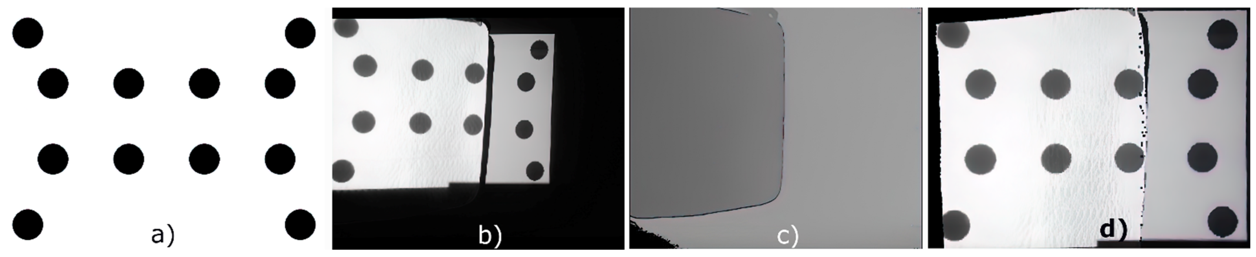
displaying the image containing the known pattern by the projector (
Figure 9a),
recording the RGB image with the resolution of 480 × 270 px (
Figure 9b),
registering the depth map with the resolution of 512 × 424 px (
Figure 9c),
detecting the circles in the RGB images,
transforming the coordinates [xi and yi] of each detected centre of the circles into the corresponding coordinates [xci and yci] in the depth map,
reading out the value with the depth Zc for each detected circle.
STEPS 1–6 are repeated for five different projection surface settings. Based on the five sets of circle centre coordinates, the information on their depth and the coordinates corresponding to them in the projector image, the 3D-to-2D transformation matrix, is computed. The result of applying this transformation to the RGB image (taking into account the corresponding depth maps) is the image displayed from the projector (
Figure 9d).
2.2. Camera-Moving Head System Calibration
The RGBD camera-moving head system calibration consists of bringing the coordinate systems of the camera, the lamp and the object itself to one system, which is the camera system. The tracked moving object in the camera system moves in the three-dimensional XYZ Cartesian system. The polar coordinate system is the system characteristic of moving heads. The calibration process is aimed at determining the dependence that makes it possible to transform the X
c, Y
c and Z
c coordinates of the object from the camera system to the corresponding r
h, α and β coordinates in the moving head system in accordance with Formula (6):
where [m
1, …., m
12] are the constant coefficients of the transformation matrix, the angle α corresponds to the angle of rotation of the lamp horizontally (0–360°) and the angle β is the angle of rotation of the lamp vertically (0–270°).
The result of the calibration process is the matrix that makes it possible to transform any point in the camera space into the corresponding point in the moving head space, thus enabling the illumination of any object in the scene. The value of twelve coefficients of the calibration matrix is determined on the basis of a dozen corresponding pairs of the coordinates of a point from the camera and moving head systems. The corresponding points are obtained by means of performing a special sequence. First, the light spot is directed to the selected point in space and the values of the pan and tilt rotation angles are read. Then, on the recorded RGB photo, this light spot is detected, and the pixel coordinates (representing the spot centre) are converted into the corresponding coordinates in the depth map where the depth value readout is carried out. The obtained x, y and z values of the image point are converted into the Xc, Yc and Zc coordinates of a point in the camera system. Based on the collected information, the calibration matrix is calculated (Formula (6)).
2.3. Dynamic Video Mapping of Moving Silhouettes
The dynamic mapping of cuboidal objects is a quick and feasible task even with the use of a single RGBD camera. The first step is to identify and assign successive vertices that ultimately make up the geometry of the mapped object to the appropriate sectors of planes. The human silhouette identification and mapping represent a significantly bigger challenge. They have to be conducted in a complex manner taking into account the multitude of dynamically changing parameters. As far as the dynamic mapping of the human body in real-time is concerned, the presented method included a process that consists of the following steps:
detecting 21 characteristic articular points of the human body (
Figure 2),
detecting the body motion and determining the body surface with the help of the background extraction method,
filling the inner part of the outline of the human body surface with any colour on the image,
drawing the human bones on the image (
Figure 6d),
fitting the final image to the projector view,
displaying the image.
The diagram of this process is shown in
Figure 10. The dynamic lighting of the moving silhouette enables the illumination of the entire human body without going beyond its contours (
Figure 6a). It also enables the illumination of the selected parts of the body, e.g., hands, legs and chest, with the light spot of an adjustable diameter (
Figure 6f). Projection mapping makes it possible to “paint” the actor’s body with any colour or a selected digital image. Additionally, it is possible to “draw” the skeleton on a moving object that reproduces its pose in real-time (
Figure 6d,e).
2.4. Human Body Motion Detection
During the research, the human body motion detection was carried out on the basis of the analysis of depth images from the RGB-D camera. In this way, the impact of the variability of the lighting conditions on the detection accuracy was minimised. In the current research phase, a simplifying assumption has been made that the image registration is performed in a room with the smallest possible proportion of glossy and transparent surfaces because such surfaces cause a decrease in precision of the captured depth maps [
44].
In order to detect the actor’s motion, the background extraction method was used. This method enables the precise separation of image points that correspond to the moving foreground objects. It is based on comparing the current image frame with its predefined approximation representing the background. It should be emphasised that building a virtual background requires an in-depth analysis and is not a purely graphic background extraction. Background modelling consists of capturing 10 consecutive images of the depth of the recorded scene. Then the background at each point is determined as the arithmetic average of these images, excluding the extreme values. In the background modelling process, it is crucial to carry out the registration of the depth maps without a moving human body in the scene. The next step of motion detection is capturing the current frame where the moving object is already visible in the field of view of the camera. Later the background image extraction from the current depth map is performed. The result of the difference is a spatial image of the living object, whose non-zero pixels represent a moving person and noise (
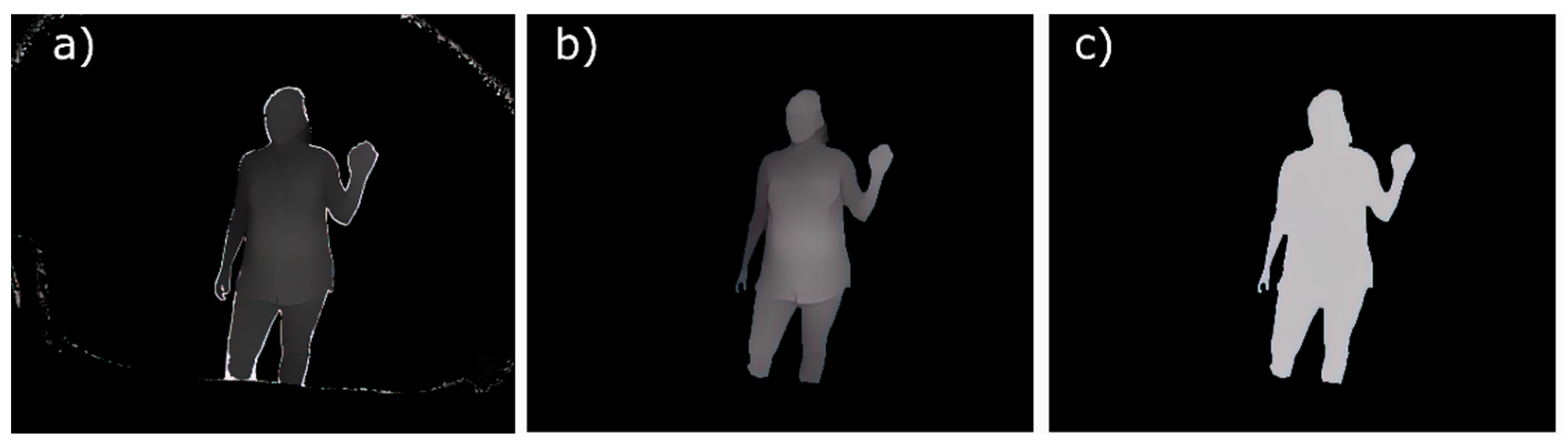
Figure 11a).
Two problems are the source of these noises. The first problem arises from the fact that in the process of creating a depth map, the pixels may have inconsistent values at the edges of objects in the scene. This happens because some reflected light comes from the object, and some light comes from the background. Mixing this information together can create flying pixels [
45]. The second type of noise arises from the slight differences (at the level of 0.5%) between the values of the corresponding pixels in the background image and the current depth map. Thus, removing the non-zero pixels involves two basic steps—the threshold applications and morphological operations. During the conducted research, two thresholds were used. The first threshold was 0.5% of the maximum recorded value of the depth in the scene. All pixels were zeroed below this value. The second threshold was the value close to the depth value of a flat surface, e.g., a wall on which the projection was made. The pixels’ value that was higher than this threshold were deleted. Finally, the Erode morphology operation eliminated the noise that had not been zeroed in the thresholding process. If there were “discontinuities” within the area of the moving object, the close morphological operation was additionally performed. This function means filling small holes and bays within an object without changing its shape.
The result of the background extraction method is shown in
Figure 11b. For the purposes of lighting and dynamic “painting” of a moving body, the final image is transformed into a binary mask (
Figure 11c).
2.5. Dynamic Projection Lighting of a Human Body
The dynamic lighting of a silhouette in real-time consisted of illuminating the entire human body without going beyond its contours (
Figure 6a). During the research, the illumination of specific parts of the body, e.g., hands, was obtained by displaying the light spots of a controlled diameter and colour (
Figure 6c,f). The verification of the correct identification of the silhouette and its current pose was based on “drawing” the lines on the human body that reflected the shape of the human skeletal parts (
Figure 6d,e). Finally, the dynamic projection mapping was carried out, which consisted of “painting” the body surface with any image.
The 3D-to-2D function (Formula (4)) was used to implement both the dynamic lighting and dynamic mapping of the body. In order to show the difference in the duration and computational complexity of the developed transformation for grey and colour images, two mapping variants were performed:
Variant I—first the 3D-to-2D transformation was performed for the binary map (using the 3D-to-2D function for the monochrome images), then the body was “painted” and the skeleton was drawn.
Variant II—drawing the skeleton and illuminating/“painting” the body surface were carried out on the image with the resolution of the depth map, i.e., 512 × 424 px. Then, the 3D-to-2D transformation for the colour images was applied to the final image.
Graphical mapping of the moving silhouette was obtained by multiplying the binary map representing the moving object with the graphical image filled with any colour. In this version, the vector drawing time was not optimised, and therefore, the skeleton was drawn independently using some standard line drawing functions.
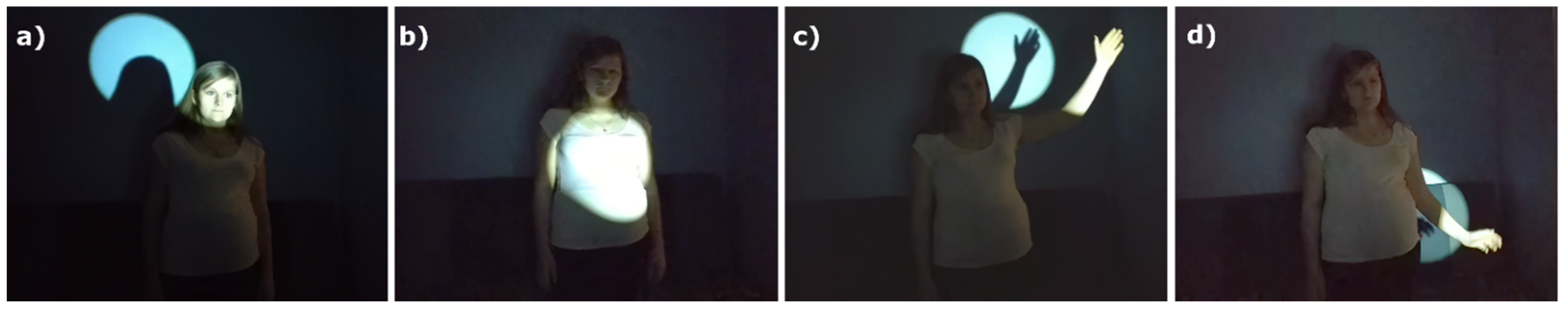
2.6. Dynamic Lighting of Silhouettes with Moving Heads
The dynamic lighting of the silhouette with a moving head enables the illumination of one specific part of the body, e.g., a hand, a head or a belly (
Figure 7). The dynamic lighting of an object is understood here as “following” a moving part with the light spot. Additionally, it is possible to adjust the diameter of the light spot to the size of the illuminated object by taking into account its current position in the scene. Using the identification of skeletal parts by the RGBD camera makes it possible to illuminate the selected part of the body in real-time. It should be noted that when it comes to the camera-moving head system, it is possible to light only a single component of the scene.
3. Results
3.1. Results without Optimisation
The dynamic lighting of the human body was performed in two variants differing in the way and the sequence of using the image transformations. In order to analyse the acquisition and processing of data during the projection on the moving silhouette the following times were measured: the depth map download along with the skeletal part detection, the motion detection, the skeleton and light spot drawing and the 3D-to-2D transformation performance.
Human body motion detection takes place with the help of depth maps with a resolution of 512 × 424 pixels. In the conducted analyses, a computer with an Intel Core i7 9750 H (2.6 GHz) processor with 16 GB RAM was used. The presented system was developed in the Labview environment. The current version of the software is based on the sequence computation of the CPU. The next version will use the computing capabilities of the NVIDIA GeForce GTX 1660 Ti graphics accelerator.
The time of simultaneous depth map download and detection of twenty characteristic human skeletal parts was 1.675 ms on average. The drawing process of the skeletal lines and light spots took 0.084 ms, while the time of the human body motion detection was 3.09 ms. Based on the analysis of the data presented in
Table 1 and
Table 2, it is possible to identify the difference in the time lengths between the 3D-to-2D function used for the greyscale image and the colour one. As for the projector resolution of 1024 × 768 pixels, these times were 3.468 and 9.55 ms, respectively. Therefore, initially, the colour image transformation took three times longer than the greyscale image transformation.
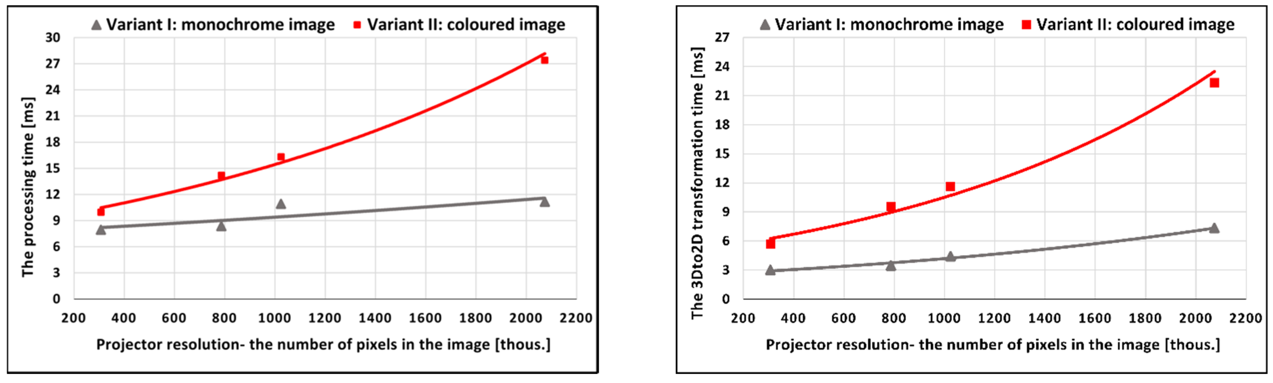
The results of the time analysis of the dynamic lighting/mapping process and the applied 3D-to-2D transformation are collected and compared in
Figure 12.
Both presented graphs show the dependence of the times on the target image resolution (the number of pixels composing the image) displayed from the projector. Both the times obtained for the 3D-to-2D transformation and the times of the mapping process were approximated by the exponential function. In graph 12, the triangular marks represent the duration of the 3D-to-2D function applied to the monochrome images and the square marks are the times for the colour image transformations. The analysis of the obtained results shows that the resolution of the displayed image has a significant impact on the total time of calculations, and consequently, on the level of generated delays between the moving silhouette’s current position and pose and the displayed image. Nevertheless, even in such complicated cases, it is possible to obtain a high fluidity of movement in relation to the illuminated object with a complication level corresponding to the human body. Even the longest time of the entire process at the level of 27.4 ms allows for obtaining almost 40 frames per second. Based on the preliminary research results, it is assumed that the optimisation of the use of the main processor, graphic processor and the separation of threads to independent computing units can improve these results at high resolutions.
3.2. Transformation Time Optimisation
Image transformation time optimisation is one of the ways of reducing the level of delays between the displayed content and the current position of a moving target. The results presented in
Section 2.1 show that they generate the greatest delay, which translates into the object mapping frequency at the same time. This is important because the higher the obtained mapping speed, the greater possibility of the dynamics of a moving object. It happens without a loss in the accuracy of fitting the content to the target.
The proposed method for optimising the image transformation times consists of performing all required transformations (including 3D-to-2D) for the reduced image resolution in reference to the native resolution of the projector. Then, the final image is scaled to the resolution of the image displayed by a projector. In order to be capable of implementing the transformations on smaller images, the camera-projector system should be calibrated to the image resolution for which the operations are performed. The scale factor between the transformed image and the image displayed from the projector should be selected so as to maintain high image quality. Thus, when it comes to projector lighting, a higher scale value can be assumed than in the case of mapping with a highly detailed image. Additionally, the best effects for the dynamic lighting of a moving object are obtained with the use of transforming the greyscale images that have a shorter processing time.
Table 3 shows the 3D-to-2D transformation times for grey and colour images for four different image scale factors.
It should be remembered that for all tested cases, a FullHD resolution is the size of the displayed (final) image. The obtained results show that it is possible to reduce the grey image processing time from 9.879 to 2.967 ms, i.e., even three times, and as for the RGB images, this time can be reduced from a value of 22.7743 to 4.9188 ms, i.e., over four times (in the case of using a scale equal to 16).
The system calibration to a lower resolution and the image scaling to a resolution of the displayed image allows for optimising the analysed data throughput. As far as the dynamic lighting is concerned, it is possible to reduce the delay of as much as 20 ms with the help of the 3D-to-2D transformation replacement for the FullHD colour images with the transformation for 16 times smaller greyscale images (480 × 270 px). Additionally, it can be seen that in the proposed system, the delay arising from this image transformation can be reduced to the level of 3 and 5 ms for the greyscale and RGB images, respectively. However, it should be remembered that when it comes to the dynamic mapping with graphic content, it is reasonable to use a scale no higher than four. This will allow a higher mapping frequency value while maintaining a high quality of the displayed image to be obtained.
As mentioned earlier, the image transformation time optimisation makes it possible to improve the analysed data throughput. In turn, a lower level of the generated delays increases the precision of fitting of the projection image to the mapped surface and enables greater dynamics of the moving object. The accurate fitting of graphic content to a moving object is a crucial parameter from the point of view of discomfort glare reduction. It is done by means of dynamically shaping the luminance on the illuminated object with the use of multimedia projectors. In the case of the eye area, which is a small angular area, any shifts or misfits will directly translate into not obtaining the desired effect. It should be mentioned that the smart lighting system is crucial in this field. Determining only the position of the eyes and the direction of a moving object may not provide the desired effect. It is also important to estimate the speed of movement and take this information into account when preparing the luminance map applied to an object. The object moving at a speed of only 2 km/h covers a distance of 0.55 m in 1 s. Assuming 30 frames per second, when displaying a single frame of a luminance image, the object covers a distance of almost 2 cm.
3.3. Discomfort Glare Reduction
In order to verify the possibility of reducing glare in the dynamic projection lighting of a moving object, the research was conducted on the lighting of a moving human body in real-time in the following variants:
the head zone dimmed for darkening levels of 100% and 50% (
Figure 13d–f) and,
the eye zone dimmed for darkening levels of 100% and 50% (
Figure 13g–i).
The 100% darkening level meant displaying a black colour locally, whereas the 50% level was performed by means of locally applying the grey colour corresponding to the value of 127 on an 8-bit scale. Additionally, the reliability of the system was checked by taking the measurements for darkening the eye zone for different poses of the body (
Figure 13j,k).
The tests were done in a photometric darkroom at the Lighting Technology Division of Warsaw University of Technology. In the research, a projector in DLP technology from Optoma DH1017 with a resolution of 1080 p and the brightness of 4500 ANSI lumens was used. In order to visualise the masking effect for the given lighting variants better, the luminance distribution was measured using Technoteam LMK 98–3 Colour with an 8 mm lens [
46], which is an imaging luminance measuring device with a high measurement accuracy (48-bits). The obtained results are shown in
Figure 13. For a better graphic visualisation of the results, the logarithmic false colour scale was selected. The measuring system is shown in
Figure 13a. It should be added that in order to obtain the reliable results of the luminance distributions on the surface of the crucial body parts, the head zone was covered with a piece of white cloth of a diffusing reflection nature.
The analysis of the obtained data shows that the total or 50% darkening of a sensitive zone, such as the eyes or the head, enables the luminance to be reduced to a significantly low level. As far as the presented tests are concerned, these values are at the level of 2 and 6 cd/m2 for the total and 50% darkening of the zone, respectively. The luminance of white-lit areas is approximately 50 cd/m2, which means a contrast 25:1 for the 100% darkening and 25:3 for the 50% darkening. At the same time, the dramatic limitation of the luminance value allows the face to be clear and there is no effect of darkening of the head zone that adversely affects the aesthetics of the illuminated silhouette.
A high contrast ratio of the device determines masking/darkening quality of the sensitive zones of the silhouette illuminated with the projector light. It should be added that the level of the minimum black brightness (of the darkened zone) translates into the minimum luminance in the dimmed areas. Thus, the lower the black brightness level, the higher the glare reduction efficacy.
To evaluate the real luminance perception of the person looking in the direction of the projector, some measurements of the luminance distribution on the projector surface were taken. The measurements were taken from the observer’s position towards the projector lens (
Figure 14 and
Figure 15).
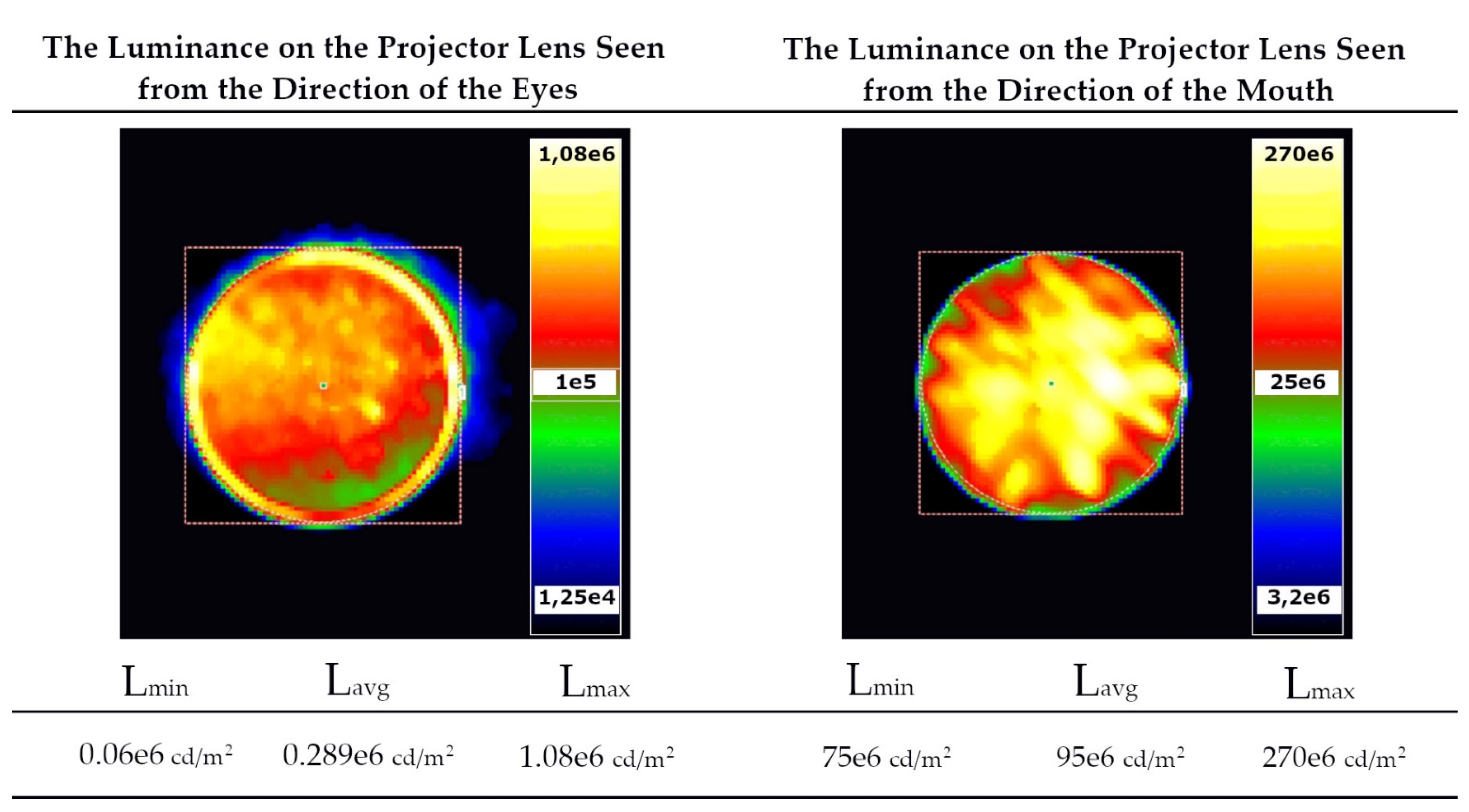
The measurements cover the luminance’s seen from the direction of the darkened eye zone (
Figure 14a) and from the fully illuminated mouth area (
Figure 14b). Both measurement systems are shown in
Figure 14. The obtained results are presented in
Figure 15, and they include the maximum and average luminance values of the part of the projector responsible for sending the light beam towards the observer’s eyes and mouth.
The analysis of data in
Figure 15 shows that the average projector luminance values seen from the direction of the face area are as high as 100 × 10
6 cd/m
2. For the typical luminance of the surroundings of the luminaires of about 50–100 cd/m
2, which means a contrast of 1,000,000:1. Whereas the average luminance seen from the direction of the darkened eye zone is about 0.3 × 10
6 cd/m
2, which gives a contrast of 3000:1.
The use of projectors with a higher contrast ratio will enable a further luminance reduction, and therefore, a further potential discomfort glare reduction. Moreover, the masking effect will be stronger for lower brightness values of the projector. The correct identification and dynamic masking makes it possible to reduce the luminance of the darkened areas, and thus, to limit the glare phenomenon.
4. Discussion and Conclusions
The broadly understood multimedia technique is a very complex field. In order to deal with it scientifically, it should be approached in an interdisciplinary way. The presented case is the perfect example of such an approach. Mathematics, physics, programming, algorithm creating and optimising are essential fields that have to be used in order to develop any unique system of dynamic graphic mapping or dynamic lighting related to the human body.
This paper presents the example of using the system, as well as the process of adjustment, calibration and analysis of the obtained results. Markerless systems based on the use of RGB-D cameras combined with multimedia projectors offer great opportunities. The key part of the system is obtaining efficient transformations that allow the local coordinate systems of individual devices into one common coordinate system to be transformed. This coordinate system is common for all recorders, supporting markers, identified objects and the entire scene.
It can be easily calculated that in order to obtain a framerate at the level of 30 frames per second, the cycle of object identification, all transformations and the final display of the image should be completed in about 30 milliseconds. However, it should be highlighted that when mapping any dynamic objects in real-time with a moving speed of only 3 km/h (0.83 m/s), the object covers 2.76 cm in the time necessary to display a single image frame. Therefore, optimisation is extremely important in order to reduce the computation time between individual image frames as to avoid any shifts and misfits of the displayed image to the object. Such a misfit may occur even though the coordinates of the object have been correctly detected. The presented problem of misfit can be reduced significantly by using artificial intelligence and without increasing the number of frames per second. Artificial intelligence helps to determine the characteristics of the object and the rate of movement of the individual parts, e.g., hands. It also shifts the image so that the next frame “hits” the object taking into account the shifts arising from the movement speed. Such a high precision needed for the implementation of dynamic projection mapping will not be necessary in the case of object lighting systems that require fluidity. However, dynamic masking of sensitive zones where discomfort glare may occur already requires a high frequency of applying appropriate masks and precision of the object position identification.
This paper focuses on the proposal of the implementation method and basic transformations necessary to perform dynamic mapping or lighting of an object with darkening sensitive zones. The results of the conducted experiments show that quick transformations of images and their optimisation allow a stable 30 frames per second using only the central processing unit (CPU). The additional separation of computing threads and the use of the computing power of graphic processors make it possible to track multiple objects within a single scene simultaneously. Additionally, the experiment carried out in a photometric darkroom (
Figure 13) enables the evaluation of the effectiveness of glare reduction by means of limiting the luminance value by 300 times within the eye zone while maintaining high aesthetics of lighting (
Figure 15). The use of projectors with a higher contrast ratio will enable a further discomfort glare reduction.
The conducted research shows that depending on the resolution of the analysed and displayed image and the sequence of the transformations performed, the analysis times from capturing the first data for displaying the image on the object are in the range of 7.9–11.1 ms for Variant I. As for Variant II the processing times of one iteration are within the range of 9.9–27.4 ms. In Variant I, the scene was analysed first in the depth map resolution, i.e., 512 × 424 px. Next, the 3D-to-2D transformation for colour images was used to obtain the final image with the native projector resolution. In Variant II, first the 3D-to-2D transformation was performed for a binary map for monochrome images. Then intra-contour lighting of the silhouette was performed, and it was enriched with the skeleton drawing.
The obtained tests results, for the method of optimizing the image transformation times, show that it is possible to improve the analysed data throughput. In the proposed system, the delay arising from the 3D-to-2D image transformation can be reduced to the level of 3 and 5 ms for the greyscale and RGB images, respectively. Therefore, the presented method allows reducing the delay of the dynamic lighting by much as 20 ms for FullHD resolution of the displayed images. It can be done by applying the scale factor of 16 for the greyscale images.
With regard to the total computation times, it should be noted that even the longest analysis time obtained for colour images with FullHD resolution (Variant II) made it possible to obtain a smooth 30 frames per second. However, it should be emphasised that one RGB-D recorder was used with a relatively low depth map resolution of 512 × 424 points. The target system variant that consists of a few high-resolution RGB-D recorders and high-resolution projectors of high frequency will be associated with a significant extension of the analysis time. Thus, in the future, it will be important to use graphics accelerators intensively and to separate computing units into an independent input and output path.
Concluding, in the future, the discussed target system can be implemented in multimedia technology, the automotive industry, autonomous vessels, etc. The next version of the system will contain smart elements in the form of genetic algorithms and neural networks for calculations and predictions of the direction and movement speed. It is worth emphasising that the Kinect devices will not be used in the next version. It is because such Kinect device has its limitations, for example, quite low resolution and estimating the depth of only several meters.
Author Contributions
Conceptualisation, S.S.; methodology, S.S., M.S.; software, M.S.; validation, S.S. and M.S.; formal analysis, S.S., M.S.; investigation, S.S. and M.S.; resources, M.S.; data curation, S.S. and M.S.; writing—original draft preparation, S.S. and M.S.; writing—review and editing, S.S. and M.S.; visualisation, S.S. and M.S.; supervision, S.S.; project administration, S.S. and M.S. All authors have read and agreed to the published version of the manuscript.
Funding
This research received no external funding.
Institutional Review Board Statement
Not applicable.
Informed Consent Statement
Not applicable.
Data Availability Statement
Not applicable.
Acknowledgments
Article Preparation Charge was covered by the Electrical Power Engineering Institute at the Warsaw University of Technology and Open Access Charge was covered by IDUB program at the Warsaw University of Technology.
Conflicts of Interest
The authors declare no conflict of interest.
References
- Von Marcard, T.; Rosenhahn, B.; Black, M.J.; Pons-Moll, G. Sparse Inertial Poser: Automatic 3D Human Pose Estimation from Sparse IMUs. Eurographics Symp. Geom. Process. 2017, 36, 349–360. [Google Scholar] [CrossRef]
- Andrews, S.; Huerta, I.; Komura, T.; Sigal, L.; Mitchell, K. Real-Time Physics-Based Motion Capture with Sparse Sensors. In Proceedings of the ACM International Conference Proceeding Series, London, UK, 12 December 2016. [Google Scholar]
- Xiao, X.; Zarar, S. A Wearable System for Articulated Human Pose Tracking under Uncertainty of Sensor Placement. In Proceedings of the IEEE RAS and EMBS International Conference on Biomedical Robotics and Biomechatronics, Enschede, The Netherlands, 26–29 August 2018; IEEE Computer Society: Washington, DC, USA, 2018; pp. 1144–1150. [Google Scholar]
- Maereg, A.; Secco, E.; Agidew, T.; Reid, D.; Nagar, A. A Low-Cost, Wearable Opto-Inertial 6-DOF Hand Pose Tracking System for VR. Technologies 2017, 5, 49. [Google Scholar] [CrossRef] [Green Version]
- Zhang, Y.; Chen, K.; Yi, J.; Liu, T.; Pan, Q. Whole-Body Pose Estimation in Human Bicycle Riding Using a Small Set of Wearable Sensors. IEEE/ASME Trans. Mechatron. 2016, 21, 163–174. [Google Scholar] [CrossRef]
- Baldi, T.L.; Farina, F.; Garulli, A.; Giannitrapani, A.; Prattichizzo, D. Upper Body Pose Estimation Using Wearable Inertial Sensors and Multiplicative Kalman Filter. IEEE Sens. J. 2020, 20, 492–500. [Google Scholar] [CrossRef] [Green Version]
- Shafaei, A.; Little, J.J. Real-Time Human Motion Capture with Multiple Depth Cameras. In Proceedings of the 2016 13th Conference on Computer and Robot Vision (CRV), Victoria, BC, Canada, 1–3 June 2016; pp. 24–31. [Google Scholar]
- Mehta, D.; Sridhar, S.; Sotnychenko, O.; Rhodin, H.; Shafiei, M.; Seidel, H.P.; Xu, W.; Casas, D.; Theobalt, C. VNect: Real-Time 3D Human Pose Estimation with a Single RGB Camera. In Proceedings of the ACM Transactions on Graphics, Los Angeles, CA, USA, 30 July–3 August 2017; Association for Computing Machinery: New York, NY, USA, 2017; Volume 36. [Google Scholar]
- Dabral, R.; Gundavarapu, N.B.; Mitra, R.; Sharma, A.; Ramakrishnan, G.; Jain, A. Multi-Person 3D Human Pose Estimation from Monocular Images. In Proceedings of the 2019 International Conference on 3D Vision (3DV), Québec City, QC, Canada, 16–19 September 2019; pp. 405–414. [Google Scholar]
- Xie, L.; Zhang, X.; Xu, Y.; Shang, Y.; Yu, Q.F. SkeletonFusion: Reconstruction and Tracking of Human Body in Real-Time. Opt. Lasers Eng. 2018, 110, 80–88. [Google Scholar] [CrossRef]
- Cao, Z.; Hidalgo, G.; Simon, T.; Wei, S.E.; Sheikh, Y. OpenPose: Realtime Multi-Person 2D Pose Estimation Using Part Affinity Fields. IEEE Trans. Pattern Anal. Mach. Intell. 2021, 43, 172–186. [Google Scholar] [CrossRef] [Green Version]
- Wang, K.; Lin, L.; Jiang, C.; Qian, C.; Wei, P. 3D Human Pose Machines with Self-Supervised Learning. IEEE Trans. Pattern Anal. Mach. Intell. 2020, 42, 1069–1082. [Google Scholar] [CrossRef] [PubMed] [Green Version]
- Zhang, Z.; Wang, C.; Qin, W.; Zeng, W. Fusing Wearable IMUs with Multi-View Images for Human Pose Estimation: A Geometric Approach. arXiv 2020, arXiv:2003.11163. [Google Scholar]
- Chen, C.; Jafari, R.; Kehtarnavaz, N. Improving Human Action Recognition Using Fusion of Depth Camera and Inertial Sensors. IEEE Trans. Hum.-Mach. Syst. 2015, 45, 51–61. [Google Scholar] [CrossRef]
- UN Regulation No. 53 Installation of Lighting and Light-Signalling Devices for L3vehicles. 2018. Available online: https://op.europa.eu/en/publication-detail/-/publication/abe063c4-37b1-11ea-ba6e-01aa75ed71a1 (accessed on 30 October 2021).
- UN Regulation No. 149 Road Illumination Devices. 2019. Available online: https://unece.org/transport/documents/2021/05/standards/un-regulation-no-149-road-illumination-devices-rid (accessed on 30 October 2021).
- Mercedes Shows Future Path for Its LED Headlights. Available online: https://www.carscoops.com/2014/11/mercedes-shows-future-path-for-its-led/ (accessed on 30 October 2021).
- Turning the Corner on Automotive Lighting. Available online: https://pl.mouser.com/applications/automotive-lighting/ (accessed on 30 October 2021).
- Słomiński, S.; Krupiński, R. Luminance Distribution Projection Method for Reducing Glare and Solving Object-Floodlighting Certification Problems. Build. Environ. 2018, 134, 87–101. [Google Scholar] [CrossRef]
- Słomiński, S. Identifying Problems with Luminaire Luminance Measurements for Discomfort Glare Analysis. Lighting Res. Technol. 2016, 48, 573–588. [Google Scholar] [CrossRef]
- Czyżewski, D. Research on Luminance Distributions of Chip-on-Board Light-Emitting Diodes. Crystals 2019, 9, 645. [Google Scholar] [CrossRef] [Green Version]
- Slominski, S. Potential Resource of Mistakes Existing While Using the Modern Methods of Measurement and Calculation in the Glare Evaluation. In Proceedings of the 2016 IEEE Lighting Conference of the Visegrad Countries, Lumen V4 2016, Karpacz, Poland, 13–16 September 2016; Institute of Electrical and Electronics Engineers Inc.: New York, NY, USA, 2016. [Google Scholar]
- Tyukhova, Y.; Waters, C.E. Subjective and Pupil Responses to Discomfort Glare from Small, High-Luminance Light Sources. Lighting Res. Technol. 2019, 51, 592–611. [Google Scholar] [CrossRef]
- CIE. Commission International de L’Eclairage ILV: International Lighting Vocabulary, 2nd ed.; CIE. Publication No. DIS 017/E; CIE: Vienna, Austria, 2016. [Google Scholar]
- CIE. CIE 55: Discomfort Glare in the Interior Working Environment; CIE: Paris, France, 1983. [Google Scholar]
- CIE. CIE 117: Discomfort Glare in Interior Lighting; CIE: Viena, Austria, 1995. [Google Scholar]
- CIE. CIE COLLECTION on GLARE 2002: CIE 146/147; CIE: Viena, Austria, 2002. [Google Scholar]
- Hamedani, Z.; Solgi, E.; Skates, H.; Hine, T.; Fernando, R.; Lyons, J.; Dupre, K. Visual Discomfort and Glare Assessment in Office Environments: A Review of Light-Induced Physiological and Perceptual Responses. Build. Environ. 2019, 153, 267–280. [Google Scholar] [CrossRef]
- Słomiński, S. Selected Problems in Modern Methods of Luminance Measurement of Multisource LED Luminaires. Light Environ. 2016, 24, 45–50. [Google Scholar]
- Clear, R.D. Discomfort Glare: What Do We Actually Know? Lighting Res. Technol. 2013, 45, 141–158. [Google Scholar] [CrossRef] [Green Version]
- Tashiro, T.; Kawanobe, S.; Kimura-Minoda, T.; Kohko, S.; Ishikawa, T.; Ayama, M. Discomfort Glare for White LED Light Sources with Different Spatial Arrangements. Lighting Res. Technol. 2015, 47, 316–337. [Google Scholar] [CrossRef]
- Skarżyński, K. Methods of Calculation of Floodlighting Utilisation Factor at the Design Stage. Light Eng. 2018, 26, 144–152. [Google Scholar] [CrossRef]
- Bará, S.; Rodríguez-Arós, Á.; Pérez, M.; Tosar, B.; Lima, R.C.; de Miguel, A.S.; Zamorano, J. Estimating the Relative Contribution of Streetlights, Vehicles, and Residential Lighting to the Urban Night Sky Brightness. Lighting Res. Technol. 2019, 51, 1092–1107. [Google Scholar] [CrossRef] [Green Version]
- Skwarło-Sońta, K. Skażenie Światłem: Co Dziś Wiemy o Jego Wpływie Na Funkcjonowanie Organizmu Człowieka? Kosmos 2015, 64, 633–642. [Google Scholar]
- Falchi, F.; Cinzano, P.; Elvidge, C.D.; Keith, D.M.; Haim, A. Limiting the Impact of Light Pollution on Human Health, Environment and Stellar Visibility. J. Environ. Manag. 2011, 92, 2714–2722. [Google Scholar] [CrossRef] [PubMed]
- Raynham, P. How Can Electric Lighting Contribute to Human Health and Well-Being? Lighting Res. Technol. 2021, 53, 515–522. [Google Scholar] [CrossRef]
- Du, J.; Zhang, X.; King, D. An Investigation into the Risk of Night Light Pollution in a Glazed Office Building: The Effect of Shading Solutions. Build. Environ. 2018, 145, 243–259. [Google Scholar] [CrossRef]
- Krupinski, R. Virtual Reality System and Scientific Visualisation for Smart Designing and Evaluating of Lighting. Energies 2020, 13, 5518. [Google Scholar] [CrossRef]
- Żagan, W.; Skarżyński, K. Analysis of light pollution from floodlighting-is there a different approach to floodlighting? Light Eng. 2017, 25, 75–82. [Google Scholar]
- Słomiński, S.; Sobaszek, M. Intelligent Object Shape and Position Identification for Needs of Dynamic Luminance Shaping in Object Floodlighting and Projection Mapping. Energies 2020, 13, 6442. [Google Scholar] [CrossRef]
- Cameo CLMHRGB60W User Manual. Available online: https://www.manualslib.com/manual/1065049/Cameo-Clmhrgb60w.html (accessed on 30 October 2021).
- Kodosky, J. LabVIEW. Proc. ACM Program. Lang. 2020, 4, 1–54. [Google Scholar] [CrossRef]
- Relf, C. Image Acquisition and Processing with LabVIEW; CRC Press: New York, NY, USA, 2003; ISBN 0203487303. [Google Scholar]
- Lin, K.-Y.; Hang, H.-M. Depth Map Enhancement on RGB-D Video Captured by Kinect V2. In Proceedings of the 2018 Asia-Pacific Signal and Information Processing Association Annual Summit and Conference (APSIPA ASC), Honolulu, HI, USA, 12–15 November 2018; pp. 1530–1535. [Google Scholar]
- Sarbolandi, H.; Lefloch, D.; Kolb, A. Kinect Range Sensing: Structured-Light versus Time-of-Flight Kinect. Comput. Vis. Image Underst. 2015, 139, 1–20. [Google Scholar] [CrossRef] [Green Version]
- TechnoTeam Bildverarbeitung GmbH. (n.d.). Video Photometer Imaging Light and Colour Measuring Technique. Available online: https://www.google.com.hk/url?sa=t&rct=j&q=&esrc=s&source=web&cd=&cad=rja&uact=8&ved=2ahUKEwiphOjkwfbzAhVmxosBHVW-AYQQFnoECAQQAQ&url=https%3A%2F%2Fwww.technoteamvision.com%2Fapool%2Ftnt%2Fcontent%2Fe5183%2Fe5432%2Fe5733%2Fe6644%2FLMK_web_eng.pdf&usg=AOvVaw2YtIuMytyeSTwNs8rLYrGm (accessed on 30 October 2021).
Figure 1.
Diagram of a dynamic lighting system operation.
Figure 1.
Diagram of a dynamic lighting system operation.
Figure 2.
Characteristic skeletal parts of the human body.
Figure 2.
Characteristic skeletal parts of the human body.
Figure 3.
Presentation of implementation of the adaptive lighting system in the automotive industry [
17,
18].
Figure 3.
Presentation of implementation of the adaptive lighting system in the automotive industry [
17,
18].
Figure 4.
Object masking: (a) static masking of the building and (b) lighting of the moving silhouette on the stage with darkening the audience.
Figure 4.
Object masking: (a) static masking of the building and (b) lighting of the moving silhouette on the stage with darkening the audience.
Figure 5.
Changing the colour and texture of moving objects by mapping them in real-time.
Figure 5.
Changing the colour and texture of moving objects by mapping them in real-time.
Figure 6.
Dynamic lighting and mapping of the moving silhouette: (a) lighting of the entire body, (b) lighting + “drawing” of the skeleton, (f) lighting of the hand with the light spot, (c) lighting of selected skeletal parts with the light spots of different colours and diameters and (d,e) “drawing” of the skeleton.
Figure 7.
Dynamic lighting of the selected parts of the moving human body with the moving head: (a) lighting of the head, (b) lighting of the belly, (c,d) lighting of the left hand.
Figure 7.
Dynamic lighting of the selected parts of the moving human body with the moving head: (a) lighting of the head, (b) lighting of the belly, (c,d) lighting of the left hand.
Figure 8.
Coordinate system. The space recorded by the camera and the space covered by the projector.
Figure 8.
Coordinate system. The space recorded by the camera and the space covered by the projector.
Figure 9.
(a) Image displayed from the projector, (b) RGB photo, (c) depth map and (d) photo obtained as a result of the 3D-to-2D transformation.
Figure 9.
(a) Image displayed from the projector, (b) RGB photo, (c) depth map and (d) photo obtained as a result of the 3D-to-2D transformation.
Figure 10.
Diagram of the mapping process of a moving silhouette.
Figure 10.
Diagram of the mapping process of a moving silhouette.
Figure 11.
Background extraction process: (a) the background extraction result, (b) the image after the noise elimination and (c) the binary mask.
Figure 11.
Background extraction process: (a) the background extraction result, (b) the image after the noise elimination and (c) the binary mask.
Figure 12.
Graphs showing dependence of times of lighting/mapping process and 3D-to-2D transformation depending on the projector resolution.
Figure 12.
Graphs showing dependence of times of lighting/mapping process and 3D-to-2D transformation depending on the projector resolution.
Figure 13.
Glare reduction test: (a) the measuring system, (b) the photo with the lighting of the entire human body, (c) the luminance measurement in the case of illumination of the entire body, (d) the photo with 100% darkening of the head zone, (e) the luminance measurement for 100% darkening of the zone, (f) the luminance measurement for 50% darkening of the head zone, (g) the photo with 50% darkening of the eye zone, (h) the luminance measurement for 100% darkening of the eye zone, (i) the luminance measurement for 50% darkening of the eye zone, (j) the luminance measurement for 100% darkening in the eye zone in position 2 and (k) the luminance measurement for 50% darkening in the eye zone in position 3.
Figure 14.
Measurement systems of the luminance seen from the direction of (a) the masked eyes and (b) the illuminated mouth.
Figure 14.
Measurement systems of the luminance seen from the direction of (a) the masked eyes and (b) the illuminated mouth.
Figure 15.
Results of the luminance measurements on the projector lens seen from the direction of the observer’s eyes and mouth.
Figure 15.
Results of the luminance measurements on the projector lens seen from the direction of the observer’s eyes and mouth.
Table 1.
Results of data processing times for dynamic video mapping of the silhouette—Variant I.
Table 1.
Results of data processing times for dynamic video mapping of the silhouette—Variant I.
| | Projector Resolution (px) |
|---|
| 640 × 480 | 1024 × 768 | 1280 × 800 | 1920 × 1080 |
|---|
| | t (ms) | t (ms) | t (ms) | t (ms) |
|---|
| Depth map download + 2D-joint detection | 1.0466 | 1.06802 | 2.80535 | 1.7318 |
| Motion detection | 3.78447 | 3.6654 | 3.62598 | 2.00265 |
| Line and light spot drawing | 0.11508 | 0.148826 | 0.0602972 | 0.0573873 |
| 3D-to-2D transformation | 3.00361 | 3.46833 | 4.41862 | 7.35504 |
| Process time | 7.94976 | 8.350576 | 10.91025 | 11.14688 |
Table 2.
Results of data processing times for dynamic video mapping of the silhouette—Variant II.
Table 2.
Results of data processing times for dynamic video mapping of the silhouette—Variant II.
| | Projector Resolution (px) |
|---|
| 640 × 480 | 1024 × 768 | 1280 × 800 | 1920 × 1080 |
|---|
| | t (ms) | t (ms) | t (ms) | t (ms) |
|---|
| Depth map download + 2D-joint detection | 1.18519 | 1.66958 | 1.74626 | 2.14655 |
| Motion detection | 2.99407 | 2.91301 | 2.90321 | 2.85899 |
| Line and light spot drawing | 0.0787271 | 0.0691919 | 0.0668369 | 0.07804 |
| 3D-to-2D transformation | 5.68981 | 9.5561 | 11.5979 | 22.3315 |
| Process time | 9.947797 | 14.20788 | 16.31421 | 27.41508 |
Table 3.
Results of the 3D-to-2D image transformation times for different image scale factors.
Table 3.
Results of the 3D-to-2D image transformation times for different image scale factors.
| | Projector Resolution (px) |
|---|
| 480 × 270 | 640 × 360 | 960 × 540 | 1920 × 1080 |
|---|
| Image scale factor | 16 | 9 | 4 | 1 |
| | t (ms) | t (ms) | t (ms) | t (ms) |
| Greyscale image | 2.96715 | 3.06079 | 4.0989 | 9.87963 |
| Coloured image | 4.91883 | 5.69578 | 8.92842 | 22.7743 |
| Publisher’s Note: MDPI stays neutral with regard to jurisdictional claims in published maps and institutional affiliations. |
© 2021 by the authors. Licensee MDPI, Basel, Switzerland. This article is an open access article distributed under the terms and conditions of the Creative Commons Attribution (CC BY) license (https://creativecommons.org/licenses/by/4.0/).


