1. Introduction
The Demonstration Power Plant (DEMO) Balance Of Plant (BOP) integral thermal-hydraulic models have been developed by VTT Technical Research Centre of Finland Ltd. using the Apros system code. Such activities have been facilitated by the BOP work package of the EUROfusion Consortium [
1], elaborating on two blanket concepts, namely the Helium-Cooled Pebble Bed (HCPB) and the Water-Cooled Lithium–Lead (WCLL) Breeding Blanket (BB) configurations [
2,
3]. In order to map the potential advantages and shortcomings of these plants, several BOP layouts have been investigated focusing on different Primary Heat Transfer System (PHTS) and Power Conversion System (PCS) coupling techniques.
The subsequent variants can be divided into direct and indirect coupling schemes. In the case of direct coupling, the PHTS is directly connected to the PCS via steam generators, whereas in the indirect layout, the primary–secondary systems’ interface is represented by an Intermediate Heat Transfer System (IHTS), equipped with an Energy Storage System (ESS) [
4]. The direct coupling approach has two models, a pure direct version with an AUXiliary Boiler (AUXB) and another, incorporating a small ESS. The former variant served only as a benchmark case, with the ultimate goal of studying the pulsed operation regime of the power plant using a gas-fired boiler. In dwell, the boiler provided a modest steam supply, alleviating the effects of the pulsed operation of DEMO heat sources [
5]. Referring back to the small ESS configuration, instead of an auxiliary boiler, a molten salt loop was implemented, connected to the PCS via a Molten Salt Steam Generator (MSSG).
Although the basic engineering principles of the DEMO plants have been appropriated from conventional nuclear power plant design, the operating regime of the tokamak (toroidal chamber with magnetic coils, Rus.: ТОрoидальная КАмера с МАгнитными Катушками) is a fundamental departure. The plasma current in the reactor chamber is driven by the discharge of the central solenoid until the plasma current reaches its opposite peak current. This implies that the tokamak has to operate in pulsed mode where a pulse period (∼7200 s) is followed by a dwell phase (∼600 s) when only the decay heat is produced (∼1–3% ). Such a pulsed operation connotes challenges in the design with regard to electricity production in a commercially and technically viable way.
VTT has been contributing to the BOP work package with various analyses, concerning the outlined plant variants using the Apros system code [
6]. The present article disseminates the results of the analytical work related to the HCPB BOP small ESS configuration.
Section 2 introduces the general architecture of the PHTS (§
2.1) and the PCS with an emphasis on the Helical Coil Steam Generator (HeSG) model. The corresponding control logics are given in §
2.2, and the small ESS is introduced briefly in §
2.3.
Section 3 gives a depiction of the integral Apros model detailing the main subsystems in a similar manner as
Section 2 with more focus on the mentioned key components (§
3.1 to
3.4). The results of the transient analysis are laid out in
Section 4, finally leading the reader to the conclusions and outlook of the work in
Section 5 and
Section 6, respectively.
2. HCPB BOP Small ESS Configuration
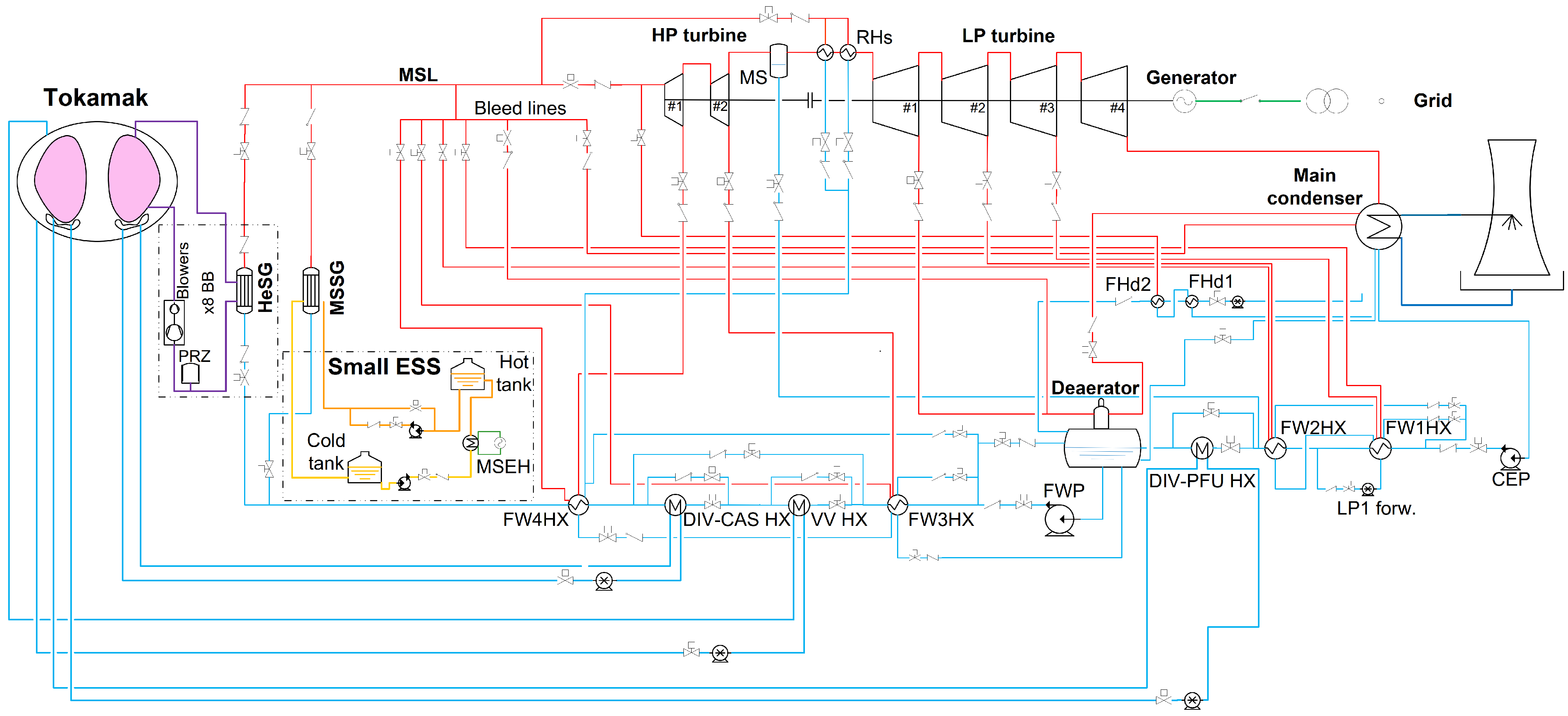
The HCPB BOP operates with a helium-cooled primary system, composed of eight coolant loops with a pair of circulators in each loop. The coolant loops pass through the First Wall (FW) and Breeding Zone (BZ) compartments of the breeding blanket, i.e., unlike the WCLL BB, the helium-cooled system incorporates concurrent heat exhaust systems for FW and BZ domains. The PHTS layout implies that the eight helical coil steam generators serve as the primary–secondary system interface with helium as the primary and pressurized water as the secondary coolant. The design of the secondary power sources is shared with the WCLL configuration, and the Divertor Cassette (DIV-CAS), Divertor Plasma Facing Unit (DIV-PFU), and Vacuum Vessel (VV) loops are connected to the PCS via three Heat exchanger (HX) pairs. The helical coil SGs represent a parallel circuit, where eight HeSGs are placed on the longer (FAR) and shorter (NEAR) feedwater collectors, four on each collector. The Main Steam Line (MSL) mixes fresh steam from the SG headers before reaching the inlet of the HP stage of the Steam Turbine (ST). The CAD layout of the facility is depicted in
Figure 1, highlighting the mentioned subsystems.
The transient scenarios enveloped two consecutive pulse-dwell phases where the pulse (= 100%, = 100% (molten salt electrical heater), 5%) and dwell section (= 1%, 38%, = 100%) lasted 7200 s and 600 s, respectively. The plasma ramps represent asymptotic time-dependent power functions describing the reactor’s thermal power variation between 1% and 100% under 100 s. The unloading of the turbine initiates 500 s ahead of the plasma power ramp-down, achieving an acceptable −10%/min power gradient on the turbine. As the reactor power winds down, radiative and volumetric heat loads drop in the blanket and secondary power sources. Balancing this power reduction, the small ESS discharge line is activated, loading up the molten salt SG. During the 10 min dwell phase, a 10% load has to be maintained on the turbine throughout the dwell, by a suitable re-alignment of the whole power conversion system.
2.1. Primary Heat Transfer System
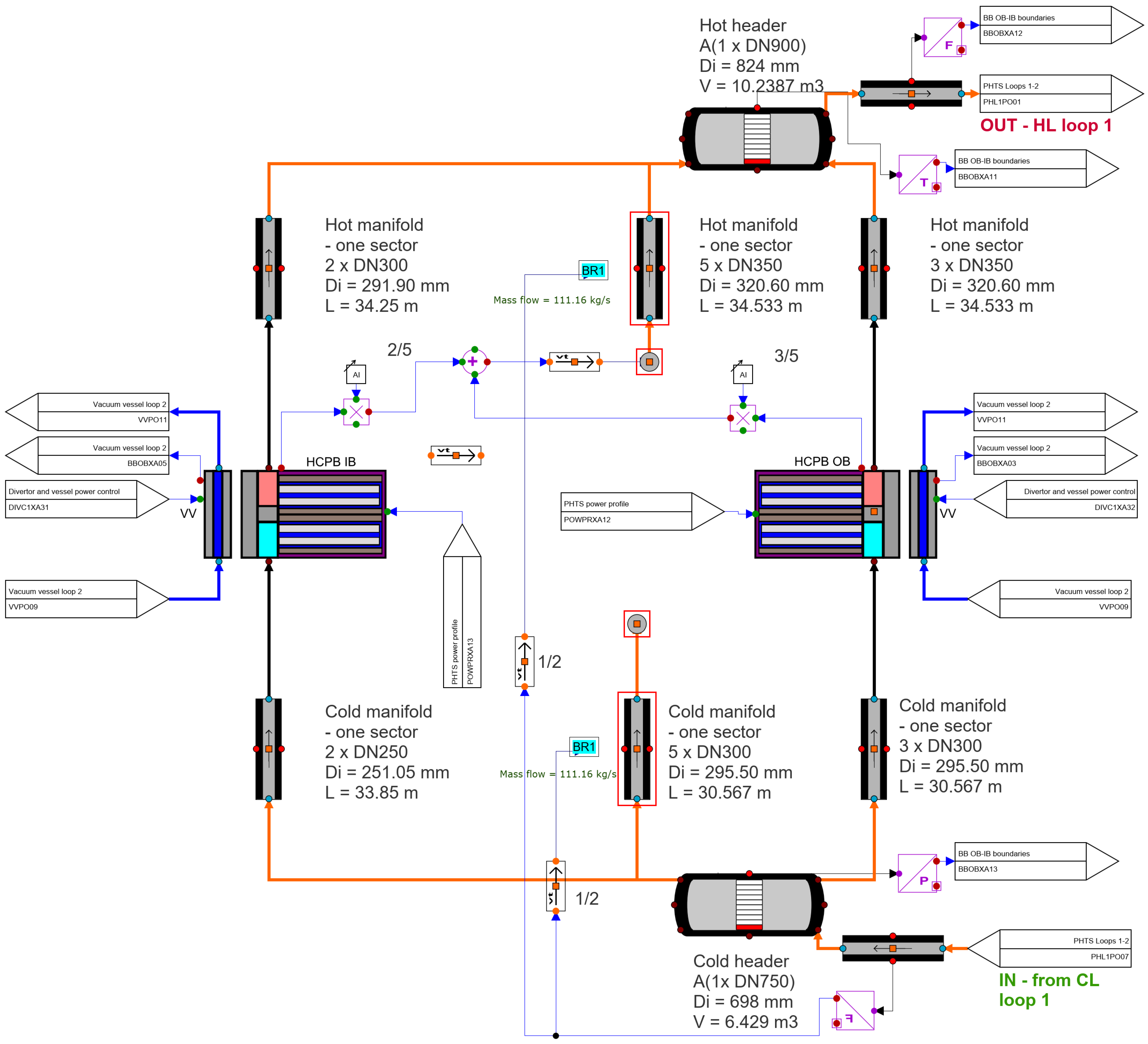
The PHTS consists of four short and four long coolant loops giving eight loops for sixteen blanket sectors. The coolant medium is pressurized helium, circulated by a compressor pair in each loop. A closer depiction of a 1/16 BB sector can be seen in
Figure 2, where the inlet and outlet manifolds are highlighted with respect to Inboard (Left, LIB; Right, RIB) and Outboard (Left, LOB; Center, COB; Right, ROB) fingers. The cold helium (marked with blue in
Figure 2b) flows through the inlet piping, reaching the segments (2 IB + 3 OB/sector), where the gas enters the FW channels via the inlet manifolds before passing through the fuel-pin breeder channels (green in
Figure 2b). At the end of these triple-wall tubes, the warm helium (red in
Figure 2b) takes a U-turn, reaching the outlet chamber behind the BZ volume that encases the Be
12Ti Neutron Multiplier Material (NMM). Penetrations provide a flow path for the hot gas into the outlet manifold from the outlet chamber. After passing through the Breeder Units (BUs), the gas is collected in the hot manifolds above the reactor, finally leading to the HeSGs via the hot legs. The helium ports are located on the top of the IB segments, while for OB segments, they were placed at ∼2/3 of the segment height.
The operation scheme of the circulators has been subject to revision; in the current arrangement, the compressors are running at full speed during the pulse, while the dwell phase control is dependent on the PHTS Thermal-Hydraulic (TH) conditions; more details on these logics are provided in §
3.4. The general steady-state parameters of the PHTS are listed in
Table 1 with regard to pulse and dwell phase conditions.
2.2. Power Conversion System
The PCS was developed on the basis of common Rankine cycles of commercial (nuclear) power plants, comprising a preheater line, boiler section, steam turbine, and condenser. The preheater line can be distributed into Low-Pressure (LP) and High-Pressure (HP) sections, connected by the Deaerator (DEA). Feedwater preheaters FW(1,2)HX and the DIV-PFU HX pair are located upstream from the DEA, while high-pressure preheaters FW(3,4)HX and the DIV-CAS and VV heat exchangers are downstream from the DEA. Since there is no dedicated pressurizer system in the PCS, such a role is fulfilled by the DEA. The boiler section houses two branches, the NEAR and FAR collectors, where the labeling refers to the difference in the distance from the FW4HX outlet junction (the FAR collector is 164 m longer than the NEAR). Each feedwater collector supplies a chain of four helical coil SGs with 228.2 °C water at 132.4 bar. The coolant is evaporated and superheated to ∼430–450 °C in the helices of the HeSGs. The molten salt SG uses the same helical coil layout as the HeSGs, with HITEC
® as the primary coolant. The HITEC
® salt is a eutectic mixture of water-soluble, inorganic salts of NaNO
3–NaNO
2–KNO
3 [
7]. The MSSG collectors are located closer to the turbine island; hence, its steam collector joins the main steam line downstream from the FAR and NEAR branches. The MSL supplies the turbine, which has two high-pressure and four low-pressure stages with an intermediate Moisture Separator (MS) and two Reheaters (RHs). Bleed lines from the MSL and extraction lines from the turbine stages feed the HXs of the preheater line, maintaining steady conditions throughout the entire operation. Closing the Rankine cycle of the PCS, the exhausted steam is condensed in the main condenser; hereafter, the Condensate Pump (CEP) delivers the fresh coolant to the FW1HX inlet. The layout of the HCPB small ESS plant is depicted in
Figure 3 with respect to the subsystems marked also in
Figure 1. The general properties are provided in
Table 2 in the pulse and dwell phase conditions.
2.3. Small Energy Storage System
The small ESS design was based on large-scale industrial molten salt storage system technology utilizing HITEC
® salt. The salt loop has no connection to the PHTS; hence, an electrical heater warms up the salt, and this component is connected to the plant’s inner grid as other on-site consumers, e.g., coolant pumps. The pulse phase operation principle is as follows: The charging molten salt pump delivers the coolant of the cold tank (288 °C) to the electrical heater. After warming up the salt (to 500 °C), the flow is directed into the hot tank. The discharge pump supplies the MSSG with the hot salt; after passing through the SG, the cold HITEC
® salt is collected in the cold tank. For the depiction of the system, the reader is advised to return to
Figure 1 and
Figure 3. The total MS inventory yields 921 t, 884 t in total from the hot and cold tanks, and 37 t in the pipe system, which includes the salt masses of the recirculation line and the tube side of the MSEH.
3. Apros Model
The Advanced Process Simulation (Apros) system code has been developed by VTT Technical Research Centre of Finland Ltd., and Fortum since 1986. The code provides three-equation (homogeneous) and six-equation solutions for one-dimensional TH problems utilizing a staggered space discretization scheme. The state variables are calculated in the center of the mesh cells (nodes), the flow related variables are derived at the border of adjacent cells. Considering heat transfer modeling, a vast array of analytical and empirical correlations is available, in addition, a new formula can be implemented using Simantics Constraint Language (SCL) scripts. SCL is a functional programming language used for scripting purposes in Simantics-related products (
https://www.simantics.org/, accessed on 4 June 2021). As a result of the EUROfusion-related work, nested User Components (UCs) were developed in order to provide a higher-fidelity solution with respect to blanket and helical coil SGs. In this case, the homogeneous model has been applied to the nodes of the small ESS and the PHTS, while the six-equation solution has been used in every other node, filled with water/steam.
The general structure of the integral model can be seen in
Figure 3 featuring some additional elements compared to
Figure 1; these extra components were requisites of satisfying plant control (e.g., ST steam dump line, make-up and let-down piping, and steam feed lines).
Providing a basis for further comparison, the cycle net efficiency (
) has been derived for pulse and dwell phase, following the formulation given in [
4] by:
where
is the gross power on the ST shaft,
is the total pumping power of the PCS, and
,
,
, and
are the heat inputs from the breeding blanket, divertor (PFU and CAS), and vacuum vessel HXs and MSSG, respectively. Furthermore, the overall plant net average efficiency (
) was also calculated as:
where
is the length of a full cycle (7800 s) and
is the total power of on-site consumers (total pumping power and MSEH).
3.1. Primary Heat Transfer System
Following the evolution of the design, the 18-sector layout was updated based on 2017–2019 materials provided by EUROfusion partners [
8]. The new BB model incorporates one IB and one OB model, describing average segments of a 22.5° sector. The arrangement of these nested Apros process components is shown in
Figure 4, featuring also boundary conditions that represent another IB segment and two OB segments in terms of enthalpy and flow rates.
A homogeneous model has been applied in every TH node on the primary side; the thermophysical properties of helium were defined according to the report of the National Institute of Standards and Technology [
9]. Each segment model contains a first wall, a BZ-Back Support Structure (BSS), and a vacuum vessel compartment. The FW and BZ Heat Structures (HSs) are coupled via heat conduction, while the BSS and VV sections are in radiative contact. The breeding zone domain is modeled by a lattice of solid heat structures, denoting the Advanced Ceramic Breeder (ACB) and neutron multiplier volumes. The thermophysical functions (
,
k) of the NMM material were derived by lumping together the properties of the multiplier material and structural steel elements, according to volume ratios that correspond to the IB and OB geometries. The coolant loops have been modeled explicitly considering four short and four long loops, and the relevant integral geometry parameters are listed in
Table 3. As
Section 3 pointed out, the TH nodes of the PHTS utilized the homogeneous model; the layout of Loop #1 is depicted in
Figure 5.
3.2. Power Conversion System
The helical coil SG design was conceived of by colleagues at the University of Palermo; later, it was further developed in the cooperation of the designer and VTT. The ASME Boiler & Pressure Vessel Code standard’s Class 1 relevant section was used for the sizing of the heat exchanger [
10] since the DEMO is classified as a nuclear power plant. The current iteration of the SG incorporates 42 helical modules, each module composed of 18 helical tubes (helices), a central rod (fixing the helices’ position), and an outer cylinder, providing a confined flow channel for the helium around the coils. The cross-section of the SG is depicted in
Figure 6, where the primary coolant enters the lower plenum at the inlet ports. After passing through the annuli and the mixing chamber, the gas turns downward to flow through the modules around the helical tubes. After heat exchange, the cold gas arrives at the rest chamber and exits the SG frustum through its outlet port. Considering the secondary side, the feedwater is fed to the modules via 42 inlet tubes that deliver the coolant to the inlet spiders of the modules, which distribute the coolant among the helices. After evaporating and superheating, the secondary coolant is collected by the head spider at first, then passing through the upper tube sheet, the total steam flow exits the SG via the outlet port on the top of the upper head. As mentioned earlier, the primary side utilizes a homogeneous flow model, while the secondary side uses a six-equation heterogeneous solution. The Apros model describes one helical coil module explicitly in twelve helical process components. These process components accommodate the helium-filled volume around the tubes, the tubes themselves, the module wall, the central rod, and the shroud volume. The remaining 41/42 modules are represented by boundary conditions between the rest chamber and the upper tube sheet.
Heat transfer between helium and the HX tubes’ outer surface has been calculated using the Žukauskas correlation [
11], while the treatment of secondary side heat transfer demanded a novel approach. The correlation package of Apros, relevant for helical geometries, has been utilized for such purposes [
12]. The main parameters of the steam generators can be found in
Table 4; note that the architecture of the MSSG is identical to the HeSG for the time being. Apart from the TH differences, the only departure from the helium–water SG is that the primary coolant medium was switched to HITEC
®.
The remaining components of the PCS were modeled using basic Apros process components such as heat exchangers, various valves, pumps, tanks, and turbine elements.
3.3. Small Energy Storage System
The small ESS has been modeled explicitly featuring the elements described in §
2.3. The recirculation line of the discharge pump enabled a soft control of the salt flow rate, where the motor speed is kept at a constant 100%. During the pulse phase, the Control Valve (CV) of the recirculation line is fully open; in dwell, the CV closes, directing the total salt flow to the primary inlet port of the MSSG. In
Section 3, it was noted that the salt loop used the homogeneous solution for its TH nodes; nonetheless, due to the uncertainties of auxiliary systems (e.g., geometry, pressure control), the salt tanks have been modeled by boundary conditions where dynamic enthalpy calculations simulated the adequate transient behaviour. The pressure of the tanks was set to 8 bar, providing a reasonable pressure profile over the system. The general parameters of the small ESS model can be found in
Table 5, where
refers to the cold pump flow rate (cold tank → MSEH/hot tank) and
denotes the hot pump flow rate (hot tank → recirc. line/MSSG/cold tank).
3.4. Logics
Considering power deposition, the reactor model used an asymptotic time-dependent curve for plasma ramps as the boundary condition, simultaneously in the blanket segments and secondary power sources as well.
The PHTS flow control’s development is still in progress; the model introduced hereby describes the recent iteration of the logics, which fulfills the established requirements. The control scheme envisages Cold Leg (CL) flow rate modulation according to reactor power with the constraint of the compressor inlet temperature, that is to keep as close as reasonably possible to its nominal value. This has been achieved by integrating a recirculation line on each compressor station. As the compressors are running at 100% at all times, this recirculation line adjusts the flow rate that is being sent to the blanket or fed back to the compressor’s inlet. Since the compressor power is relatively large (∼11 MWe/pair), an intercooler was also installed on the recirculation lines in the form of a boundary condition. This cooler decreases gas enthalpy in order to prevent the overheating of the machine and the recirculated gas.
On the secondary side, the turbine main control valve was following the reference heat balances’ steady-state pressures (123.5↔119.0 bar in pulse↔dwell transitions), as the turbine unload commenced bleed lines took over the preheater line heat exchangers’ pressurization from the extraction lines. Bypass lines of the FWHXs, DIV, and VV HXs guaranteed that the primary side average temperatures remained around the pulse phase values. The deaerator pressure was maintained at 3.5 bar throughout the entire operation.
4. Results
The Apros calculation envelopes two consecutive pulse–dwell cycles with a 1200 s pulse phase at the beginning. The pulse phase is 7200 s including two plasma ramps before and after the pulse period, and the dwell phase lasts 600 s; thus, one full cycle is 7800 s. The figures of §
4.1 to
4.3 show this sequence of events with grey areas marking the dwell periods.
4.1. Primary System Behaviour
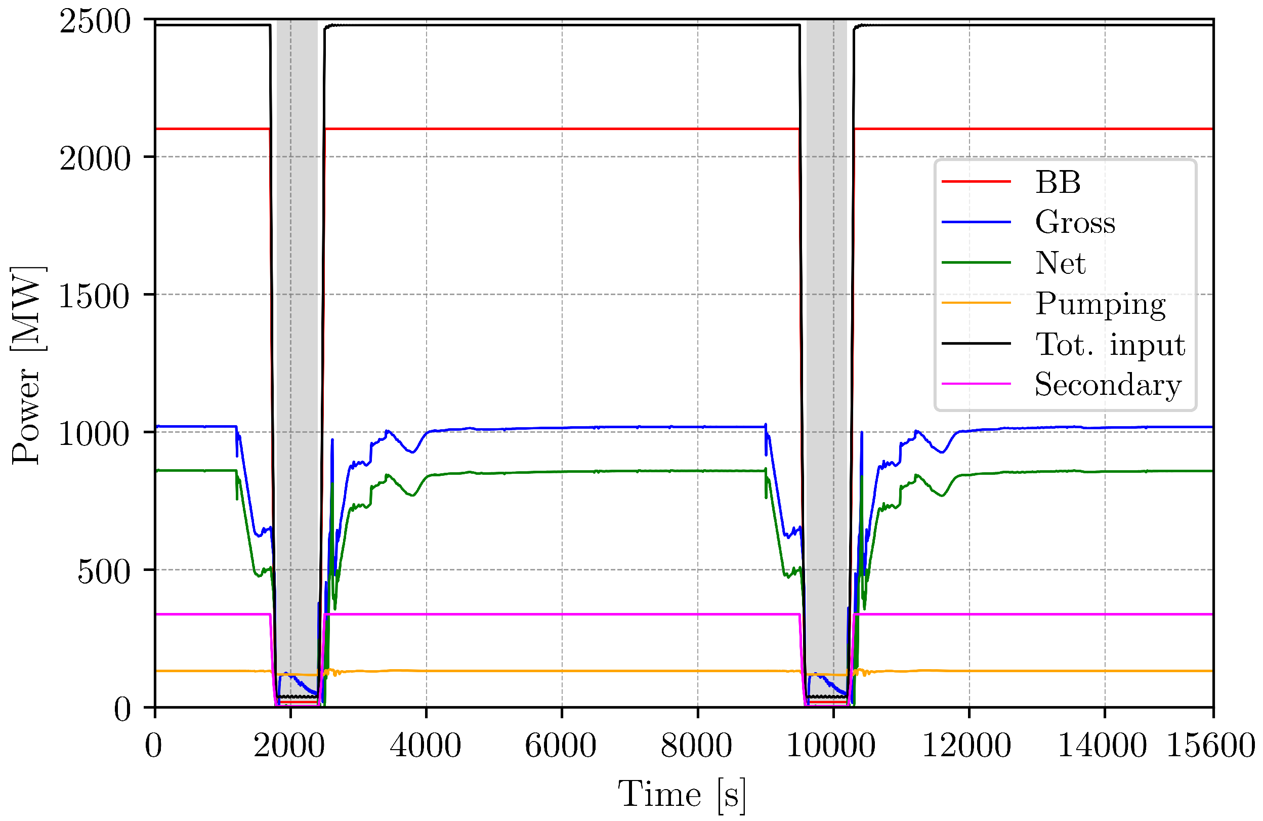
The breeding blanket, the lumped curve of DIV, and the VV loops (secondary) are compiled in
Figure 7, featuring also pumping power demands and steam turbine gross power.
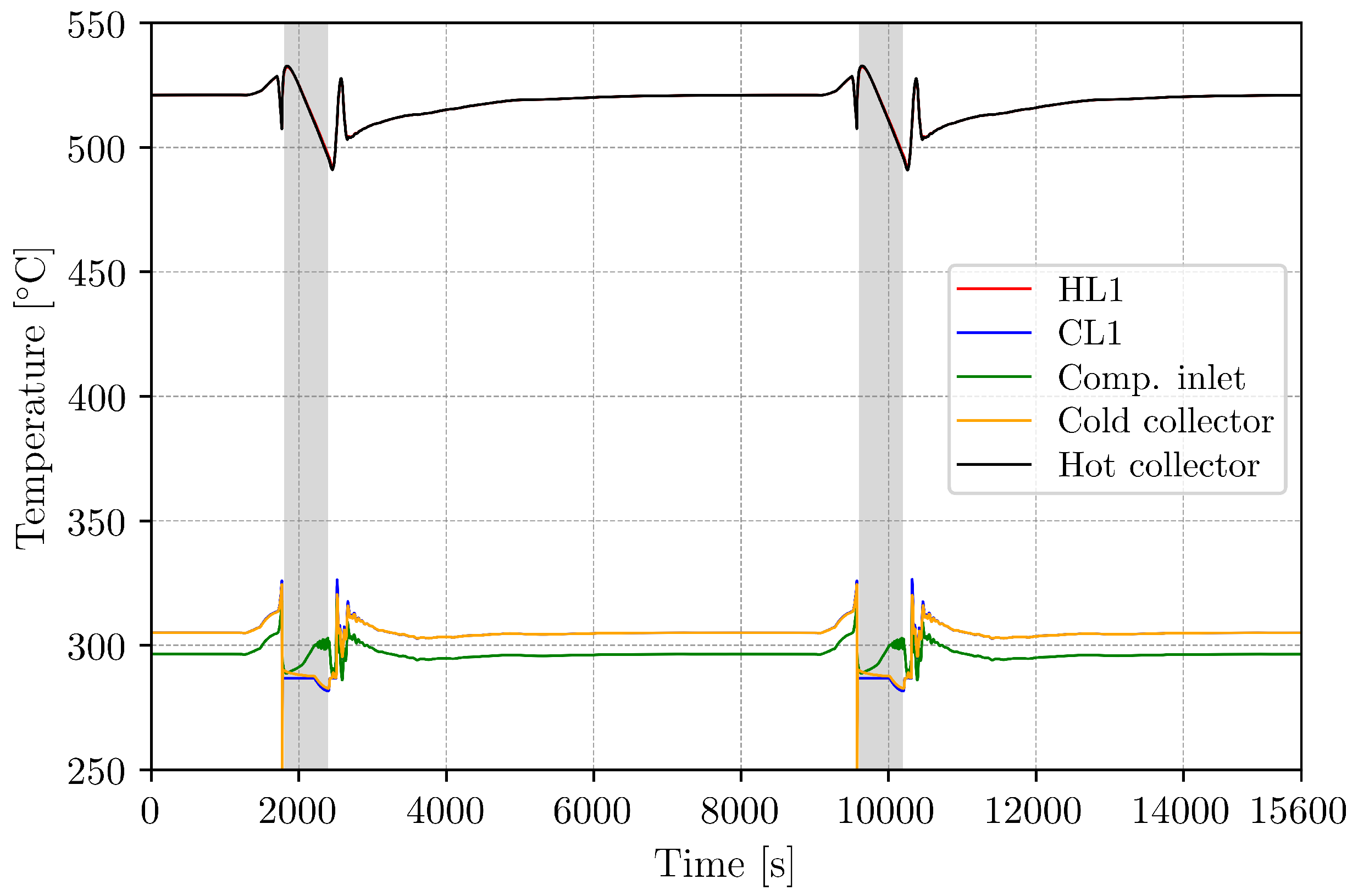
The Loop #1 helium temperatures are depicted in
Figure 8, denoting measurements in the hot and cold legs, the collectors, and the compressor inlet. The upper limit for hot leg temperatures was set at 550 °C due to the Eurofer creep temperature, while another restriction was defined for the circulator inlet temperature. During transients and dwell, the inlet temperature has to be kept as close as possible at its pulse phase value (296 °C). The transient showed that gas temperatures could reach 532–533 °C in the HL, yielding a narrow safety margin considering the earlier mentioned limit (HL1 and hot collector trends overlap in
Figure 8). The compressor inlet temperature reached 316 °C, giving a mild 20 °C increase compared to the pulse phase. Since even higher HL temperatures are permissible, the mentioned maximum compressor inlet temperature could be further lowered, should the compressor operation require so.
The PHTS pressures showed that during transients, the CL and HL pressures decreased ∼3 bar and ∼1.6 bar, respectively, while no significant change could be observed at the circulator inlet. This indicated that the recirculation line did not induce perturbations apart from a momentary 0.6 bar depression when the recirculation valve opened at a nominal loop flow rate.
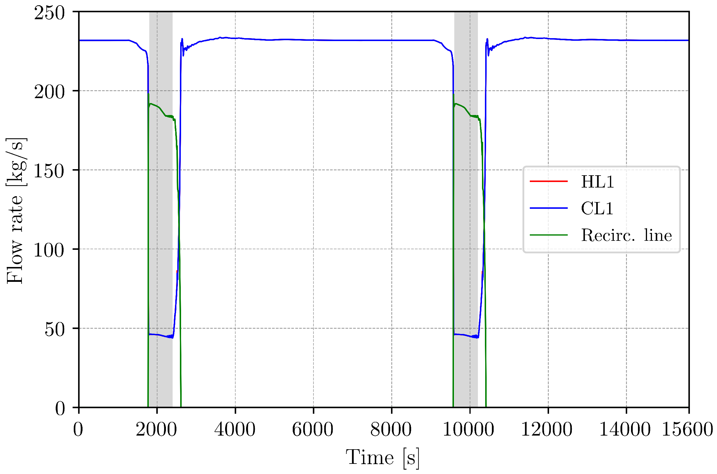
Gas flow rates in the coolant loops varied between 45 kg/s and 229 kg/s; the Loop #1 trends are shown in
Figure 9. The ramp-down and ramp-up were rather asymmetric, governed by the thermal inertia of the blanket and steam generators. As for the ramp-up, the recirculation line throttled gas flow rates in the cold legs in order to ensure low circulator inlet temperatures, still maintaining acceptable HL temperatures. Cold and hot leg flow rates overlap in
Figure 9, since in the pulse phase, the recirculation line is closed; in addition, the recirculation line is connected to the compressor suction; hence, the bypassed gas does not appear in the HL trends in dwell.
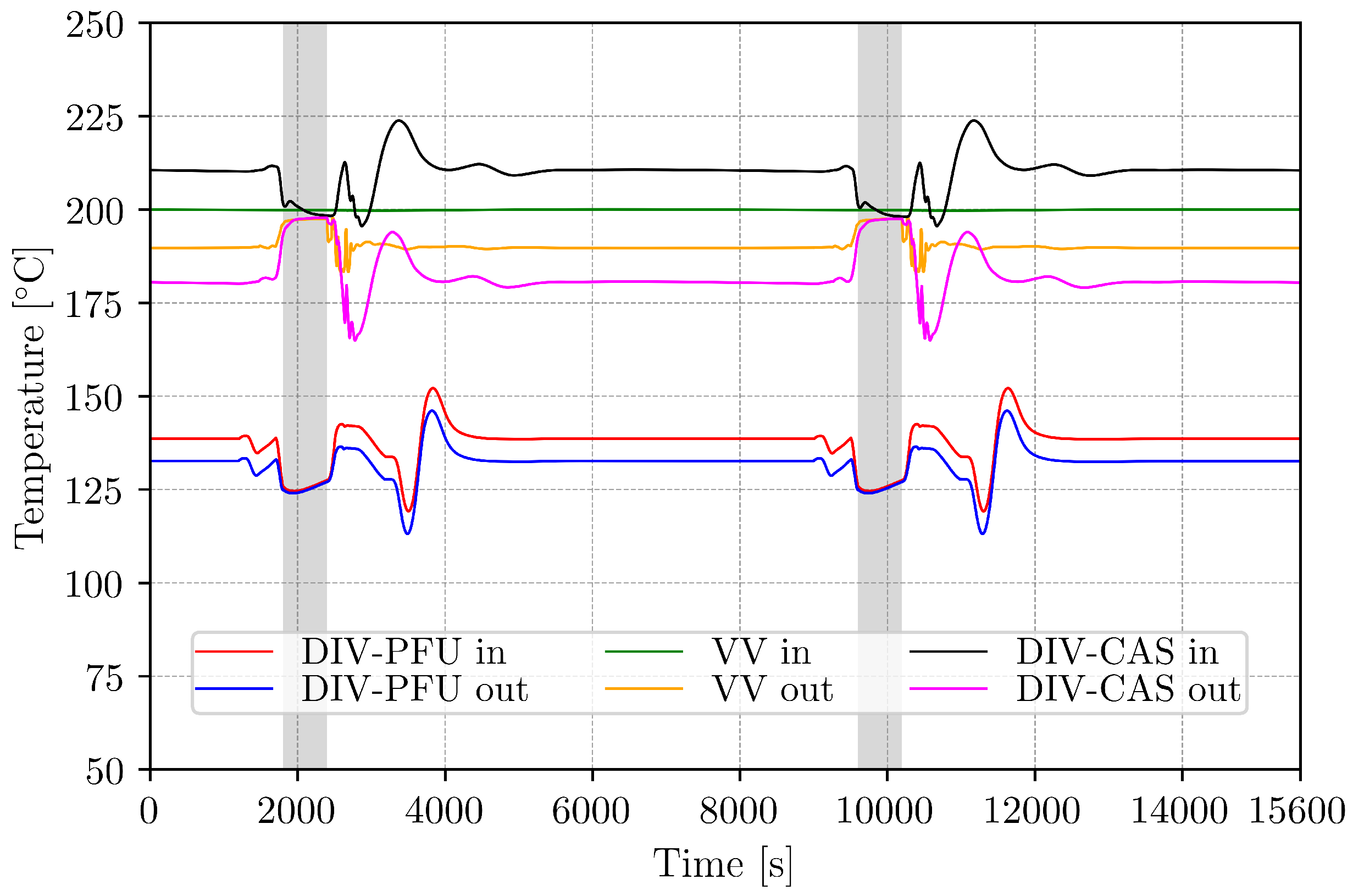
The primary side temperatures of the DIV and VV heat exchangers are compiled in
Figure 10, highlighting a notable change in the
T values. As the DIV and VV powers shift, from 100% to dwell time levels of ≈1%, the PCS (secondary) side flow rates of the corresponding HXs decrease as the bypass lines are activated. When HeSG chains restarted and flow rates rose in the feedwater collectors, the DIV-CAS and VV outlet temperatures decreased accordingly.
4.2. Secondary System Behaviour
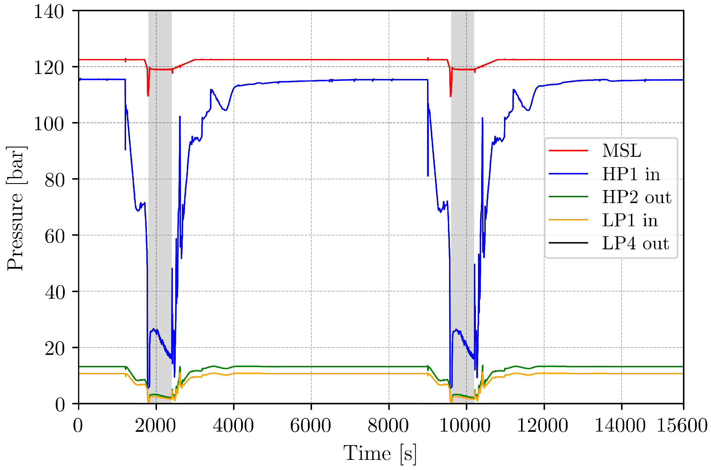
The MSL pressure was maintained at 119.0 bar during dwell, while the HP1 inlet pressure varied between 10 bar and 28 bar; the steam side pressures are given in
Figure 11. The steam generators represent a substantial source of thermal inertia (∼401 t dry mass/HeSG) aside from the BB heat capacity; eventually, a significant part of the secondary inventory was evaporated; consequently, collapsed water levels decreased in the helices by 95% by the end of dwell. The surplus steam was delivered to the main condenser via the Dump Line (DL) during turbine (un)loading, resulting in a smoother pressure regulation upstream from the turbine. The dump line was closed at the end of the ramp-down period; thus, the HP1 inlet pressure followed strictly the inlet steam flow rate.
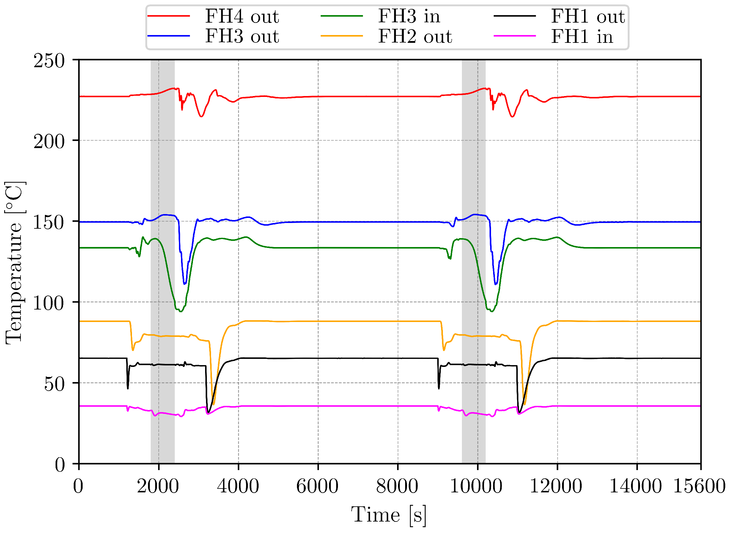
The transient trends showed steam qualities ≫99% in the collectors. As the fresh steam pressures and temperatures were sufficiently high in the MSL, the bleed lines could maintain hot conditions on the preheater line, as illustrated in
Figure 12. During the unloading process, the maximum feedwater temperature
fell ∼15 °C, although as flow rates stabilized on the preheater line, the
recovered, and the dwell phase values varied between 230–233 °C.
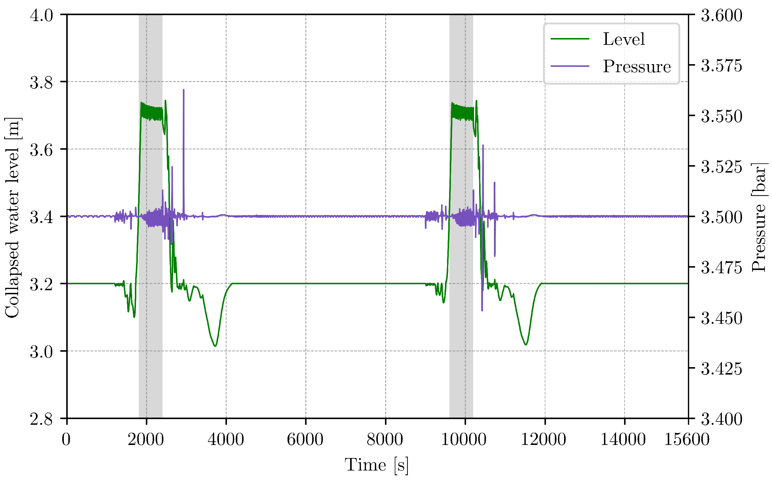
The deaerator collapsed water level varied between 3.0 m and 3.7 m corresponding to an ∼44 m
3 inventory displacement between plasma ramps. The pressure control was maintained at 3.5 bar during dwell with a ±0.1 bar margin; thus, no significant disturbance was prompted on the preheater line; the DEA behaviour is depicted in
Figure 13 with respect to the mentioned properties. Despite satisfying the PCS pressure control, the collapsed water level resembled notable variation during the transients, and such deviations could be mitigated by tuning the capacities of the DEA/condenser let-down lines and their corresponding logics.
The Apros cycle net efficiency for the PCS () in pulse and dwell was calculated as 37.6% and 21.9%, while the overall plant net average efficiency () was 30.7% integrated over one cycle.
4.3. Small ESS Behaviour
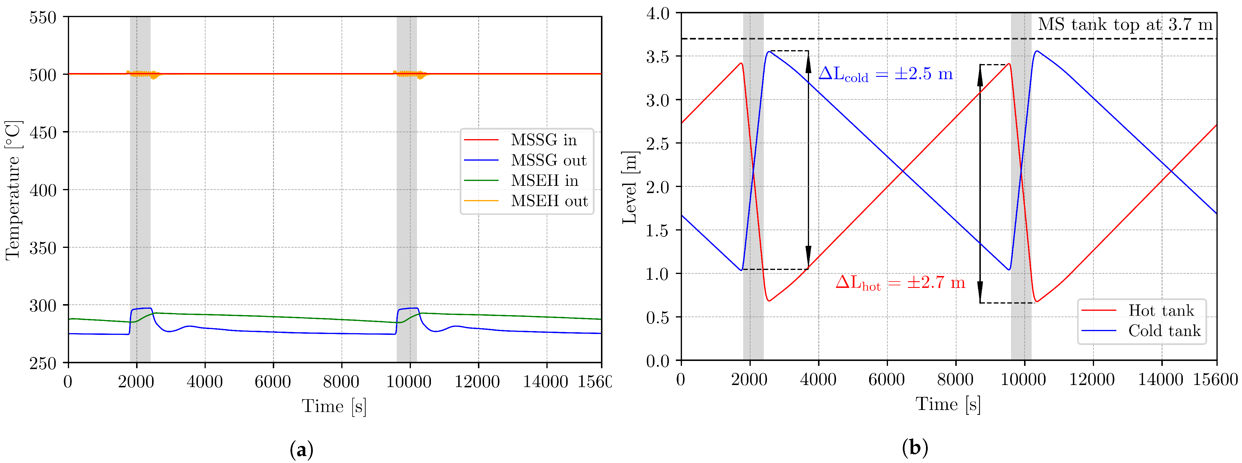
The salt temperatures are depicted in
Figure 14a, the electrical heater outlet temperature remained around 500 °C within a range of ±4 °C, implying that the current control scheme was ample. Due to the small salt tank volume and MSSG warm-up, the cold tank temperature varied by ± 5 °C. In this layout, each tank has a volume of 418 m
3, which is much smaller compared to the 1362 m
3 tank volume in the small ESS of the WCLL plant. This disparity in salt inventories already indicates that the HCPB small ESS has indeed a smaller heat capacity compared to its WCLL counterpart.
Figure 14b illustrates the molten salt levels with the top of the tanks, the level trends highlight a ±2.7 m and ±2.5 m variation for the hot and cold tank, respectively. The available free volumes above the salt highlight the challenge of future pressure control, albeit that the hereby described trends will assist developers. The results also showed that the minimum salt level at the end of the (dis)charge period yields ∼0.66–1.04 m (18–28% fill level).
5. Synopsis
Modeling efforts and transient analysis were presented considering Apros activities related to the HCPB small ESS configuration of the DEMO. A novel helical coil steam generator was introduced as the primary–secondary side interface with helium as the primary and water as the secondary coolant. The transient simulation, composed of two consecutive dwell–pulse periods, revealed that the HeSG design in its current state is a feasible option with proper gas circulator logics. It was emphasized that the various restraints, with respect to primary system operation, have a profound impact on optimization freedom regarding control logics, moreover on the PCS behaviour. The power conversion system showed noticeable, but manageable transients during plasma ramps and dwell (e.g., coolant inventory displacement), corresponding pressure and temperature variations can be considered acceptable keeping in mind the pressure decrease exceeding 100 bar at the inlet of the high-pressure turbine section.
6. Outlook
The circulator control scheme’s optimization will be a high priority task in the upcoming conceptual design phase. Due to the high degree of uncertainty considering, e.g., manufacturer and component characteristics, the logics will have to be further tailored. Hence, secondary side control systems will also have to be monitored and adjusted, should the PCS performance suggest otherwise. It has to be noted that no heat losses have been taken into consideration thus far, due to the maturity of the design. Nonetheless, based on the substantial surface area and length of the primary and secondary system piping (∼6.1 km and ∼3.5 km, respectively), when compared to commercial nuclear power plants, one has to pay close attention to the optimization of plant efficiency. One action in this direction was the addition of a pair of recuperative heat exchangers to the condenser–deaerator let-down line (see
Figure 3), where the dumped steam heats the condensate, delivered to the DEA as a result of the condenser level control. Other areas can be also identified where energy could be recovered, for instance valve stations as the large steam dump valve where the integrated enthalpy loss amounts to ≈423 kWh over a cycle. Regarding the evolution of the small ESS, the implemented boundary conditions, responsible for dynamic enthalpy calculation, will be removed as the soon-to-be published Apros service pack will provide an upgraded iteration loop, dedicated to molten salt–inert gas systems.
Author Contributions
Conceptualization, formal analysis, data curation, writing, M.S.; supervision, S.N. All authors have read and agreed to the published version of the manuscript.
Funding
This work was carried out within the framework of the EUROfusion Consortium and received funding from the Euratom research and training program 2014–2018 and 2019–2020 under Grant Agreement No. 633053. The views and opinions expressed herein do not necessarily reflect those of the European Commission.
Conflicts of Interest
The authors declare no conflict of interest.
Abbreviations
The following abbreviations are used in this manuscript:
| ACB | Advanced Ceramic Breeder | HL | Hot leg |
| Apros | Advanced Process Simulation | HP | High-pressure |
| AUXB | Auxiliary Boiler | HX | Heat Exchanger |
| BB | Breeding Blanket | IB | Inboard |
| BOP | Balance of Plant | IHTS | Intermediate Heat Transfer System |
| BSS | Back Support Structure | LIB | Left Inboard |
| BU | Breeding Unit | LOB | Left Outboard |
| BZ | Breeding Zone | LP | Low-pressure |
| CEP | Condensate Pump | MS | Moisture Separator |
| CL | Cold leg | MSEH | Molten Salt Electrical Heater |
| COB | Center Outboard | MSL | Main Steam Line |
| COND | Condenser | MSSG | Molten Salt Steam Generator |
| CV | Control Valve | NEAR | Shorter feedwater/steam collector |
| DC | Downcomer | NMM | Neutron Multiplier Material |
| DEA | Deaerator | OB | Outboard |
| DEMO | Demonstration Power Plant | PCS | Power Conversion System |
| DIV-CAS | Divertor Casette | PHTS | Primary Heat Transfer System |
| DIV-PFU | Divertor Plasma Facing Unit | RH | Reheater |
| DL | Dump line | RIB | Right Inboard |
| ESS | Energy Storage System | ROB | Right Outboard |
| FAR | Longer feedwater/steam collector | SCL | Simantics Constraint Language |
| FH | Feedwater Heater | SG | Steam Generator |
| FW | First Wall | ST | Steam Turbine |
| FWHX | Feedwater Heat Exchanger | UC | User Component |
| FWP | Feedwater Pump | VV | Vacuum Vessel |
| HCPB | Helium-Cooled Pebble Bed | WCLL | Water-Cooled Lithium-Lead |
| HeSG | Helical Coil Steam Generator | | |
Variables
The following variables are used in this manuscript:
| Cycle efficiency | | Helium pressure in HL |
| Density | | MSEH power |
| Heat transfer area | | VV power |
| Isobaric heat capacity | t | Time |
| k | Heat conductivity | | Cycle length |
| Salt charge flow rate | | Helium temperature in CL |
| Salt discharge flow rate | | Cold salt tank temperature |
| Total feedwater flow | | FH4 feedwater outlet temperature |
| Total primary He flow rate | | Feedwater inlet temperature |
| Helium pressure in CL | | Max. feedwater temperature |
| DEA pressure | | Feedwater outlet temperature |
| Helium pressure in HL | | Helium temperature in HL |
| Fresh steam pressure | | Hot salt tank temperature |
| BB power | | Compressor inlet temperature |
| DIV power | | Fresh steam temperature |
| Fusion power | | Gross power |
| ST gross power | | PCS pumping power |
| Total HeSG power | | Plant power |
References
- Turnyanskiy, M.; Neu, R.; Albanese, R.; Bachmann, C.; Brezinsek, S.; You, J.H. European roadmap to the realization of fusion energy: Mission for solution on heat-exhaust systems. Fusion Eng. Des. 2015, 96–97, 361–364. [Google Scholar] [CrossRef] [Green Version]
- Hernández, F.; Pereslavtsev, P.; Kang, Q.; Norajitra, P.; Kiss, B.; Nádasi, G.; Bitz, O. A new HCPB breeding blanket for the EU DEMO: Evolution, rationale and preliminary performances. Fusion Eng. Des. 2017, 124, 882–886. [Google Scholar] [CrossRef]
- Nevo, A.D.; Arena, P.; Caruso, G.; Chiovaro, P.; Di Maio, P.A.; Eboli, M.; Martelli, E. Recent progress in developing a feasible and integrated conceptual design of the WCLL BB in EUROfusion project. Fusion Eng. Des. 2019, 146, 1805–1809. [Google Scholar] [CrossRef] [Green Version]
- Barucca, L.; Bubelis, E.; Ciattaglia, S.; D’Alessandro, A.; Del Nevo, A.; Giannetti, F.; Vallone, E. Pre-conceptual design of the EU DEMO balance of plant systems: Objectives and challenges. Fusion Eng. Des. 2021, 169, 112504. [Google Scholar] [CrossRef]
- Szogradi, M.; Norrman, S.; Bubelis, E. Dynamic modeling of the helium-cooled DEMO fusion power plant with an auxiliary boiler in Apros. Fusion Eng. Des. 2020, 160, 11970. [Google Scholar] [CrossRef]
- Official Apros Website. Available online: https://www.apros.fi/ (accessed on 3 June 2021).
- Sohal, M.S.; Ebner, M.A.; Sabharwall, P.; Sharpe, P.B. Engineering Database of Liquid Salt Thermophysical and Thermochemical Properties; INL/EXT-10-18297 Rev. 1; Idaho National Laboratory: Idaho Falls, ID, USA, 2013; p. 24.
- Hernández, F.A.; Pereslavtsev, P.; Zhou, G.; Neuberger, H.; Rey, J.; Kang, Q.; Dongiovanni, D. An enhanced, near-term HCPB design as driver blanket for the EU DEMO. Fusion Eng. Des. 2019, 146, 1186–1191. [Google Scholar] [CrossRef]
- Arp, V.D.; McCarty, R.D.; Friend, D.G.B. Thermophysical Properties of Helium-4 from 0.8 to 1500 K with Pressures to 2000 MPa; NIST Technical Note 1334 (Revised); National Institute of Standards and Technology: Boulder, CO, USA, 1998; pp. 80303–83328.
- American Society of Mechanical Engineers. ASME Boiler & Pressure Vessel Code, Section III—Rules for Construction of Nuclear Facility Components, Division 1—Subsection NB for Class 1 Components; American Society of Mechanical Engineers: New York, NY, USA, 2019. [Google Scholar]
- Kakaç, S.; Liu, H.; Pramuanjaroenkij, A.B. Heat Exchangers: Selection, Rating and Thermal Design, 3rd ed.; CRC Press, Taylor & Francis Group: Boca Ration, FL, USA, 2012; pp. 33487–33742. [Google Scholar]
- Leskinen, J.; Ylätalo, J.; Pettini, R. Extending thermal-hydraulic modeling capabilities of Apros into coiled geometries. Nucl. Eng. Des. 2020, 357, 110429. [Google Scholar] [CrossRef]
| Publisher’s Note: MDPI stays neutral with regard to jurisdictional claims in published maps and institutional affiliations. |
© 2021 by the authors. Licensee MDPI, Basel, Switzerland. This article is an open access article distributed under the terms and conditions of the Creative Commons Attribution (CC BY) license (https://creativecommons.org/licenses/by/4.0/).


