Abstract
The bearings of a flywheel energy storage system (FESS) are critical machine elements, as they determine several important properties such as self-discharge, service life, maintenance intervals and most importantly cost. This paper describes the design of a low-cost, low-loss bearing system for a 5 kWh/100 kW FESS based on analytical, numerical and experimental methods. The special operating conditions of the FESS rotor (e.g., high rotational speeds, high rotor mass, vacuum) do not allow isolated consideration of the bearings alone, but require a systematic approach, taking into account aspects of rotor dynamics, thermal management, bearing loads and lubrication. The proposed design incorporates measures to mitigate both axial and radial bearing loads, by deploying resilient bearing seats and a lifting magnet for rotor weight compensation. As a consequence of minimized external loading, bearing kinematics also need to be considered during the design process. A generally valid, well-structured guideline for the design of such low-loss rolling bearing systems is presented and applied to the 5 kWh/100 kW FESS use case.
1. Introduction
Abandoning fossil fuel-based energy generation and moving towards clean renewable electricity must be considered to be one of the most important steps in decarbonization. Reducing the use of fossil fuels is an important measure for alleviating global warming as a result of CO2 emissions according to the Paris Climate Agreement. Though the projected increase of energy sources such as wind and solar can indeed be seen as a rather positive development, several related challenges will arise for the energy industry, such as supply companies and grid operators, and finally the customers. Especially the continuously rising electricity demand (also triggered by the increase of electric mobility) combined with increasing supply through volatile sources leads to high loads on the grid. These high loads may cause instabilities or even blackouts.
One of the key technologies in combating these problems is energy storage. While there are many different energy storage technologies available today, each serving a different purpose [1], flywheel energy storage systems (FESS) have proven to be suitable for a great variety of tasks [2], such as grid stability [3], or as buffer storage in high-power applications (e.g., brake energy recuperation of vehicles [4]). The system presented in this paper was designed as buffer energy storage to be integrated in electric vehicle (EV) fast charging stations in order to mitigate loads on the grid. More detailed information on this approach and the entire project “FlyGrid” can be found in [5]. However, the FESS might be used for many other applications in the energy supply sector or other industries.
2. Motivation and Current State of the Art
2.1. Bearing Systems in Currently Available FESS
Flywheel energy storage has been around for centuries, even flywheel powered vehicles have been known since 1792 [6]. By now, there are many companies that build and distribute FESS, either for stationary (e.g., grid stability) or mobile (i.e., brake energy recuperation in hybrid vehicles) applications. With respect to bearing design, both active magnetic bearings and rolling element bearings have been successfully used [1]. It must me mentioned that the bearings of a flywheel energy storage system are critical machine elements, as they determine several important properties such as self-discharge, service life, maintenance intervals and most importantly cost. Table 1 gives an overview of the most relevant commercially available and prototype FESS, indicating whether mechanical or magnetic bearings were used. Taking into account that automotive FESS primarily use rolling element bearings due to the higher stiffness necessary to cope with vehicle dynamics [7], the reader can come to the conclusion that there is no clear tendency towards one or the other bearing system. However, high cost of FESS in general has been identified as one of the major shortcomings of this technology, potentially preventing market penetration [8], which led the authors to focus on the more economic grease lubricated rolling element bearings (REBs) within the scope of this publication. It must be mentioned at this point that active magnetic bearings (AMBs) also require additional touch-down bearings, which are normally realized using rolling bearings.

Table 1.
Overview of most commercially available and prototype FESS and their main characteristics including used bearing types.
Research in Low-Cost, Low-Loss FESS Bearings
Despite the abundancy of commercially available and research prototypes in FESS development presented in Table 1 in the previous section, specific information on either cost or power loss of each system is scarce. While some manufacturers may provide information about self-discharge (e.g., “spin down time: ~24 h”), it is impossible to distinguish whether this means spin-down to 0 rpm, or to the lowest operating speed of the motor-generator at which energy can still be extracted from the system. Furthermore, the share of the aerodynamic losses of the system is also unknown and no conclusions can be drawn regarding bearing torque loss. However, there are some works, which indeed describe bearing systems comparable to the one presented in this paper and allow a performance comparison to a certain extent. Three examples are:
- I
- “Experimental Characterization of Low-Speed Passive Discharge Losses of a Flywheel Energy Storage System” by M. Skinner and P. Mertiny [22].
- II
- “Flywheel Energy Storage System with Spherical Spiral Groove Bearing” by J.-I. Itoh and N. Yamada [23].
- III
- “Flywheel energy storage system with a permanent magnet bearing and a pair of hybrid ceramic ball bearings” by S. Jiang, W. Hongchang and S. Wen [24].
Based on the state-of-the-art overview, the following conclusions can be drawn:
- To assess the torque loss of rolling bearings in FESS, windage losses must also be considered/isolated, which requires thorough evacuation of the tested flywheel system.
- Passive discharge losses in FESS are rarely dealt with in the literature, with the following publications presenting similar methods and results:
- ○
- Skinner and Mertiny’s paper [22], for instance, focuses on windage losses and a curve-fit model for overall losses, whereas the publication at hand goes into greater detail regarding bearing system design.
- ○
- Suzuki et al. [23] investigate and optimize inner bearing geometry to achieve friction loss optimization. In comparison, the publication at hand is based on off-the-shelf bearings and deals with the bearing periphery for optimization purposes. Therefore, advantages regarding cost for small batch size are be taken into account.
- ○
- Jiang et al. [24] conducted a study, which focuses on machine dynamics of a FESS rotor and include measurements of rolling bearing system power losses. A comparison with the results of the work at hand is given in Section 4.1.
2.2. Bearing and Other Losses in FESS
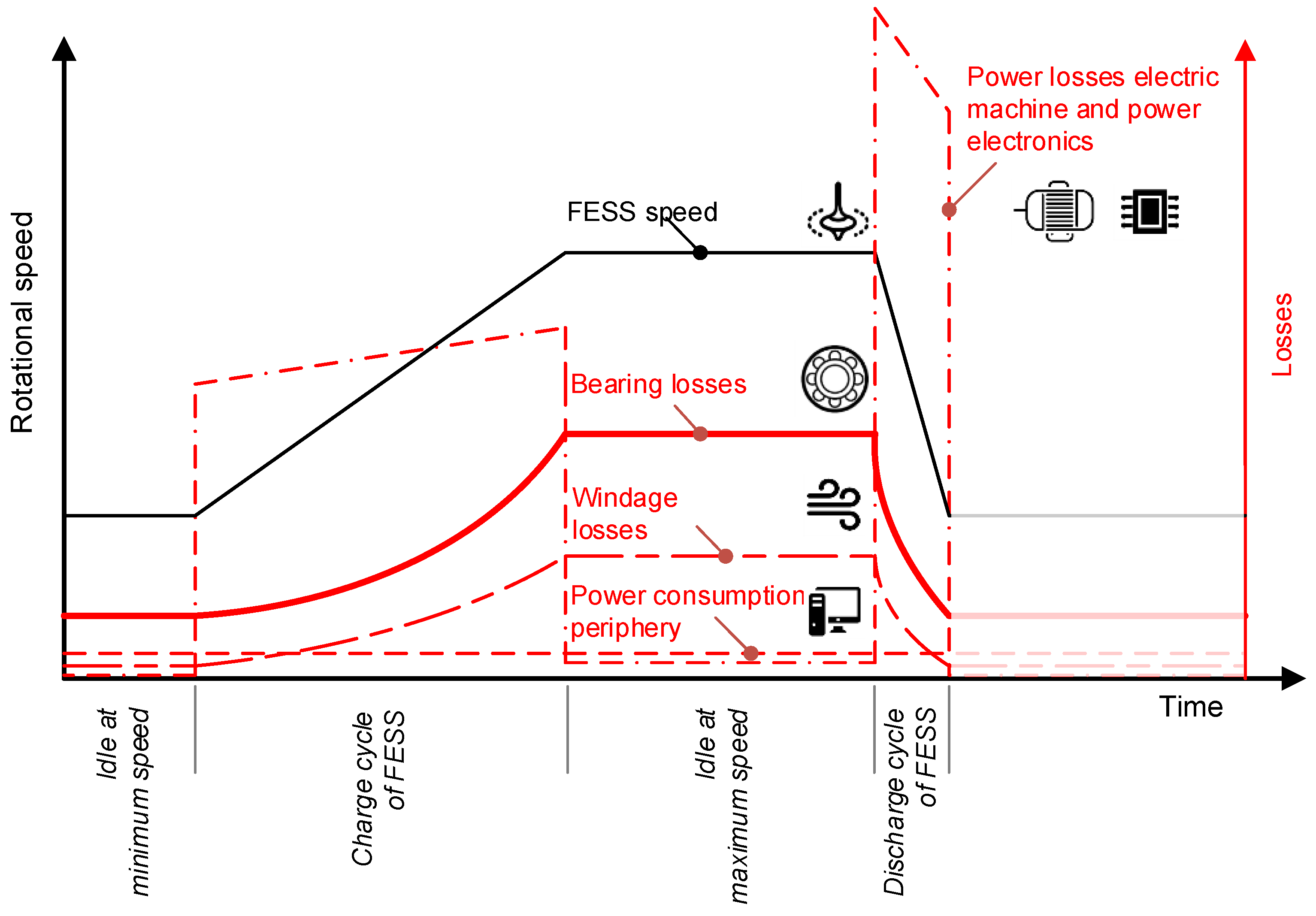
In any FESS, energy conversion and idle losses must be kept as low as possible, not only from an economic and efficiency point of view, but most importantly to avoid overheating of the system. To explain this circumstance in more detail: To reduce aerodynamic drag, the FESS rotor runs in an evacuated atmosphere, which in turn makes cooling difficult due to the absence of convection. However, windage losses are not the only losses occurring in an FESS as shown in Figure 1. Most losses depend on operating conditions, with rotational speed and ambient pressure being the most dominant ones [22].
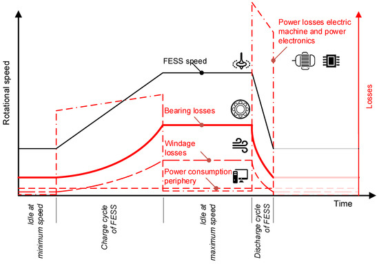
Figure 1.
Losses in a FESS over a charge-/discharge cycle.
As mentioned, special care must be taken to reduce these losses to the physically possible minimum as they strongly affect efficiency (hence also profitability) and overall thermal system behavior. The optimization of peripheral components such as power electronics, pumps, coolant circuits etc. is not considered in this publication and the focus is set on the bearing system as it determines key system properties such as:
- Self-discharge
- Service life
- Maintenance intervals
- Thermal management
- System cost
As will be shown in the upcoming sections, FESS bearings strongly interact with their environment and neighboring parts, making an isolated consideration impossible. Rather, a holistic approach for the development of a low-loss bearing system is required in order to consider all above mentioned system properties and achieve satisfying results.
2.3. Main Aim of This Work
The main aim of this work lies in the design of a low-cost, low-loss bearing system for the FESS presented in Section 2.3 and the derivative of a holistic design guideline for FESS bearing systems based on rolling element bearings. By establishing this guideline, an improvement of the state of the art through cost reduction of FESS bearing systems while at the same time enabling high reliability, long service intervals and low losses shall be enabled.
The developed design guidelines are applied to the 5 kWh, 100 kW FESS use case, including testing of the final bearing system installed in a prototype. It must be mentioned that the presented results are related to the bearing system for the CFRP rotor (or “energy module” according to Figure 2), and not the electric machine/motor-generator. However, the design methodology for the development of a motor generator bearing system operating in a vacuum is the same, with special emphasis on the thermal management presented in Section 4.
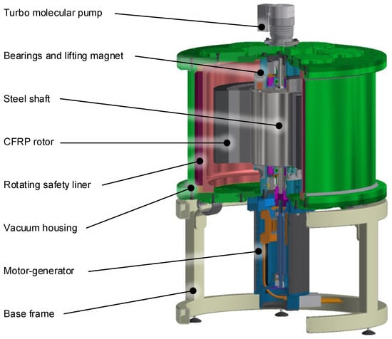
Figure 2.
CAD model of the FlyGrid FESS in a 5 kWh, 100 kW configuration.
2.4. Description of the 5-kWh–100-kW FESS
As shown in Figure 2, a so-called “non-integrated topology” [25] was chosen, due to the advantage of reduced thermal and mechanical interdependencies between the components [4]. These interdependencies may be of electric, mechanic but most importantly thermal nature, as also explained in Section 4. A separation of the electric machine and the spinning mass (rotor) is easily possible, which led to the idea of a modular design, consisting of prefabricated “energy modules” (containing the Carbon Fiber Reinforced Plastic (CFRP) rotor) and “power modules” (containing the motor-generator) that can be combined in many different ways according to the desired FESS use-case and related specifications.
However, the decision to pursue this modular approach was not only motivated by the findings presented in [5,26], revealing a significant divergence of the ideal FESS power and energy content, depending on the actual use-case of the charging station. Since production cost of the electric machine, housing and most of all CFRP rotor dominate FESS cost, it makes sense to manufacture certain modules, which offer the lowest specific cost (EUR/kWh) and combine/stack them if needed. This way, the production numbers are also increased, resulting in large batch manufacturing, further lowering costs [27].
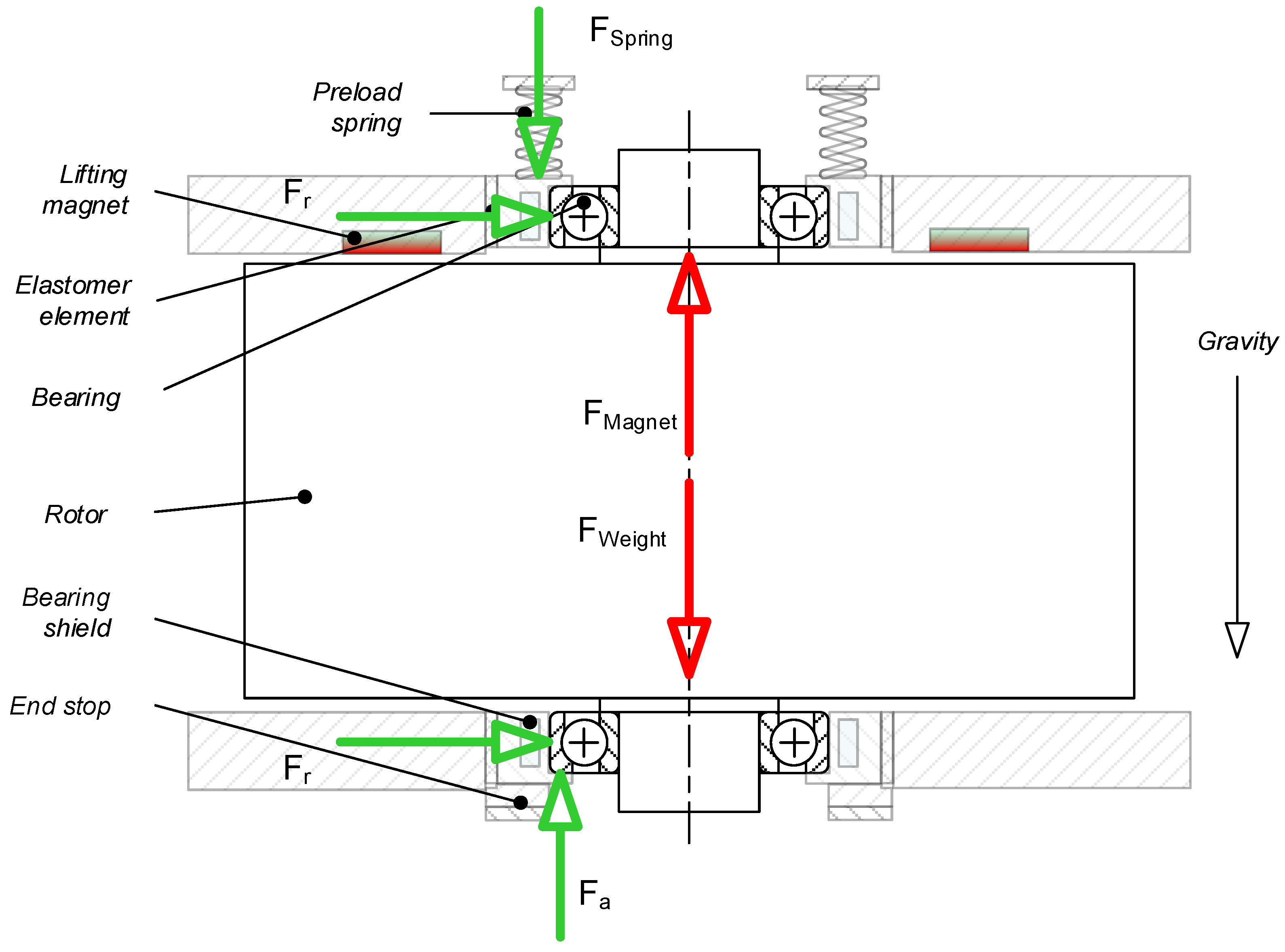
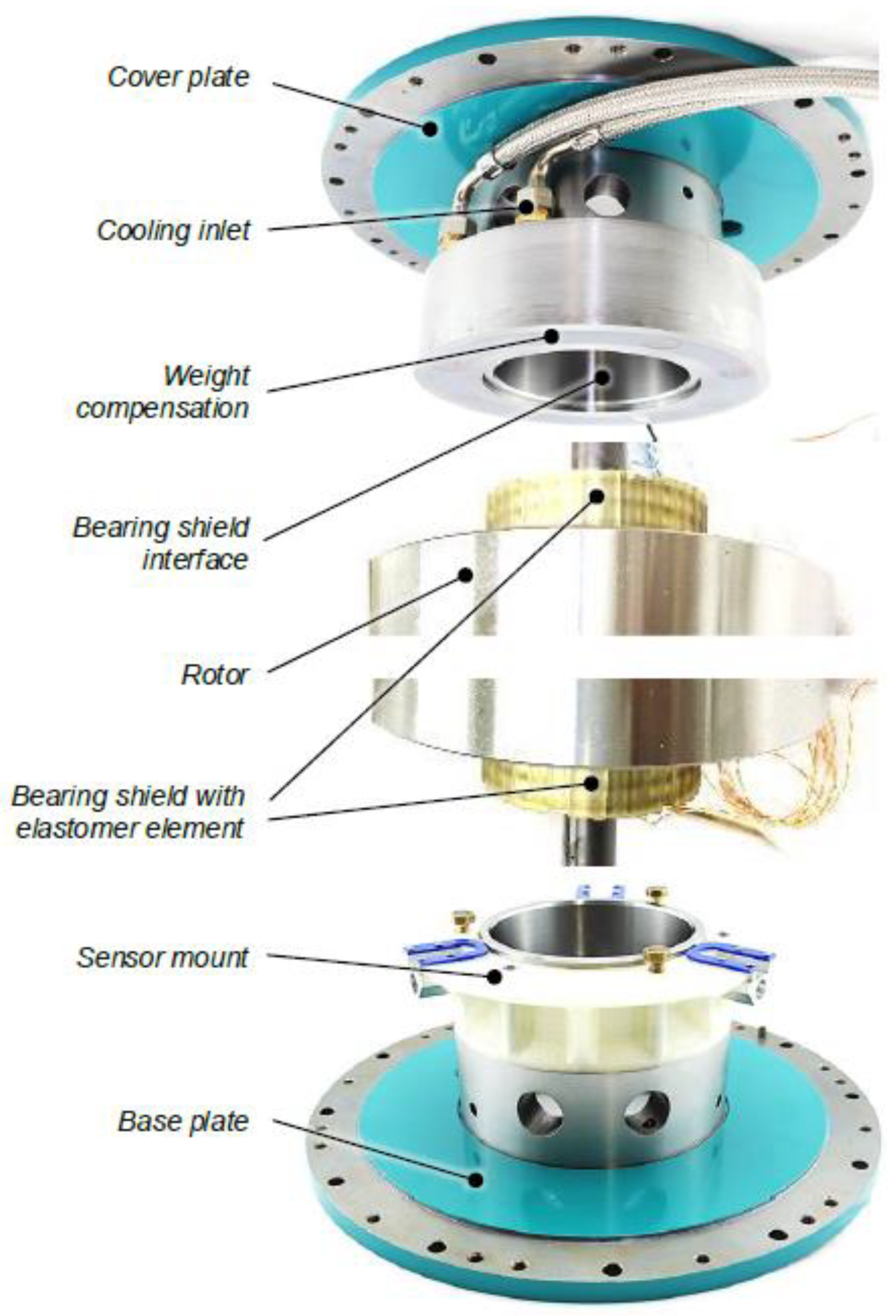
In this section, the basic design of the bearing system supporting the FESS rotor (CFRP rotor in Figure 2) is described. It consists of two angular contact spindle bearings in X-arrangement supporting a rotor that weighs 146 kg. To reach reasonable bearing service life, the rotor weight is compensated by a lifting magnet. By doing so, the bearings are axially loaded by only a fraction of the total rotor weight. Prerequisite for magnetic weight compensation is a vertical rotational axis of the rotor. The design of the magnetic weight compensation is discussed in more detail in Section 3.2.2. The mechanical bearing arrangement is axially preloaded by a spring setup that allows an accurate adjustment of the desired preload force. To allow small axial movement of the bearing (i.e., to compensate for thermal expansion effects), they are mounted in a bearing shield that is covered by an elastomer element on its outer circumference. The elastomer element further connects the bearing shields and the housing with low stiffness. This resilience is important for machine dynamics, because of the high operational speed reaching up to 30,000 rpm, as discussed in Section 3.1. For reasons of system simplicity and reduced cost, both bearings are grease lubricated and no oil supply periphery is considered. However, the methodological design approach presented in this publication is generally valid and may be applied to bearings with oil lubrication as well. For both lubrication concepts, the suitability of the lubricant at given operating temperatures and ambient pressure must be evaluated. This aspect will only be dealt with in Section 4.2 in this article, but more information about this topic can be found in [28,29]. A schematic diagram of the rotor-bearing-system is shown in Figure 3.
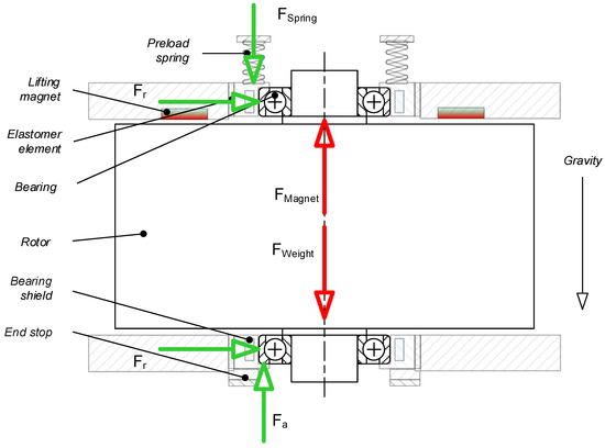
Figure 3.
Schematic diagram of the rotor-bearing-system.
2.5. Operating Parameters and Target Properties of the Projected FESS
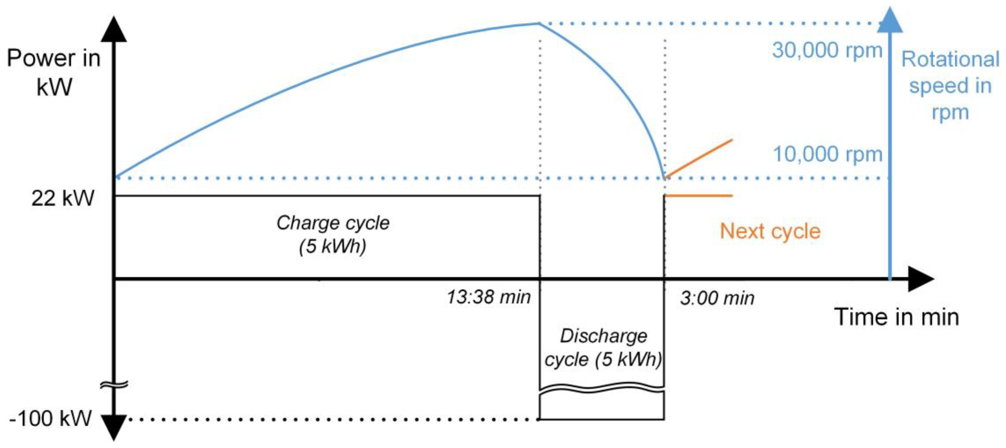
The load cycle of any FESS is of high relevance to the bearing system design and the one underlying the design of the FESS presented in this paper, is shown in Figure 4. The considered use case is integration in an EV fast charging station with the goal to provide high charging power even with only a standard 400 V/50 Hz three phase power connection (max. 22 kWel) at hand. Hence, the FESS is charged at a 22 kW rate within roughly 14 min and then discharged—as soon as an EV is connected to the charging station—at 100 kW power. In contrast to popular believe, studies have shown that most EV trips are rather short and hence a ~5 kWh energy transfer per EV charging cycle or trip is sufficient in >90% of the cases [5,26].
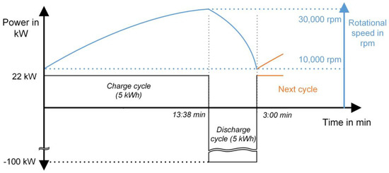
Figure 4.
FESS load cycle underlying the presented bearing design.
The load cycle is of particular interest for bearing system thermal management (see Section 4) and service life calculation, which is not dealt with in detail in this paper but can be found in [7,30,31].
3. Functional Requirements in Bearing System Design for FESS
As a result, of the special operating conditions of the FESS bearings (vacuum, high rotational speeds, etc.) it is not sufficient to consider the bearings alone. Their periphery must be taken into account during system design. This section deals with key aspects of mechanical flywheel bearing design, rotor dynamics and radial/axial bearing loads. These points can be summarized as a design methodology in a flow chart, which is presented in Section 6. In the following section the different steps within this design process of the bearing system are dealt with in detail.
3.1. Machine Dynamics
Machine dynamics of the whole system plays an important role in the bearing design for FESS. It is crucial to avoid resonance frequencies within or close to the operational speed range, which is determined by the motor generator [1]. Generally, it must be distinguished between subcritical and supercritical operation strategy. If the entire operational speed range lies below the resonance frequency it is called subcritical, if it lies above the resonance frequency it is called supercritical operation [32]. Because of the high rotor mass and maximum speed in the considered system described in Section 2.4, subcritical operation is not feasible due to the limited bearing stiffness.
For supercritical operation the bearing system’s stiffness must be reduced to avoid resonance frequencies in the FESS’s nominal operating speed range. This is achieved by the use of resilient elements that connect the bearing shield with the housing. A low-cost solution, used often in turbomachinery applications, is suspension bearing seat implementing rubber O-ring seals to decouple the outer bearing journal from the housing. Stiffness and damping strongly depend on the fitting situation when O-rings are used. Another possibility is the implementation of cast elastomer structures. While solutions using O-ring seals may be less expensive, the use of cast elastomer structures increases flexibility during system design. Special geometry may be beneficial regarding axial stiffness or sliding, which is important for the realization of axial bearing preload. Furthermore, radial stiffness can be accurately modified by the variation of shape. Both solutions were investigated by the authors [33] and are illustrated in Figure 5a,b.
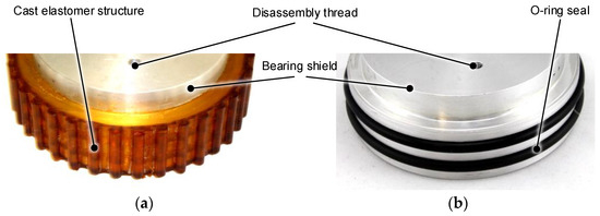
Figure 5.
Resilient suspension design: (a) casted elastomer; (b) O-ring seals.
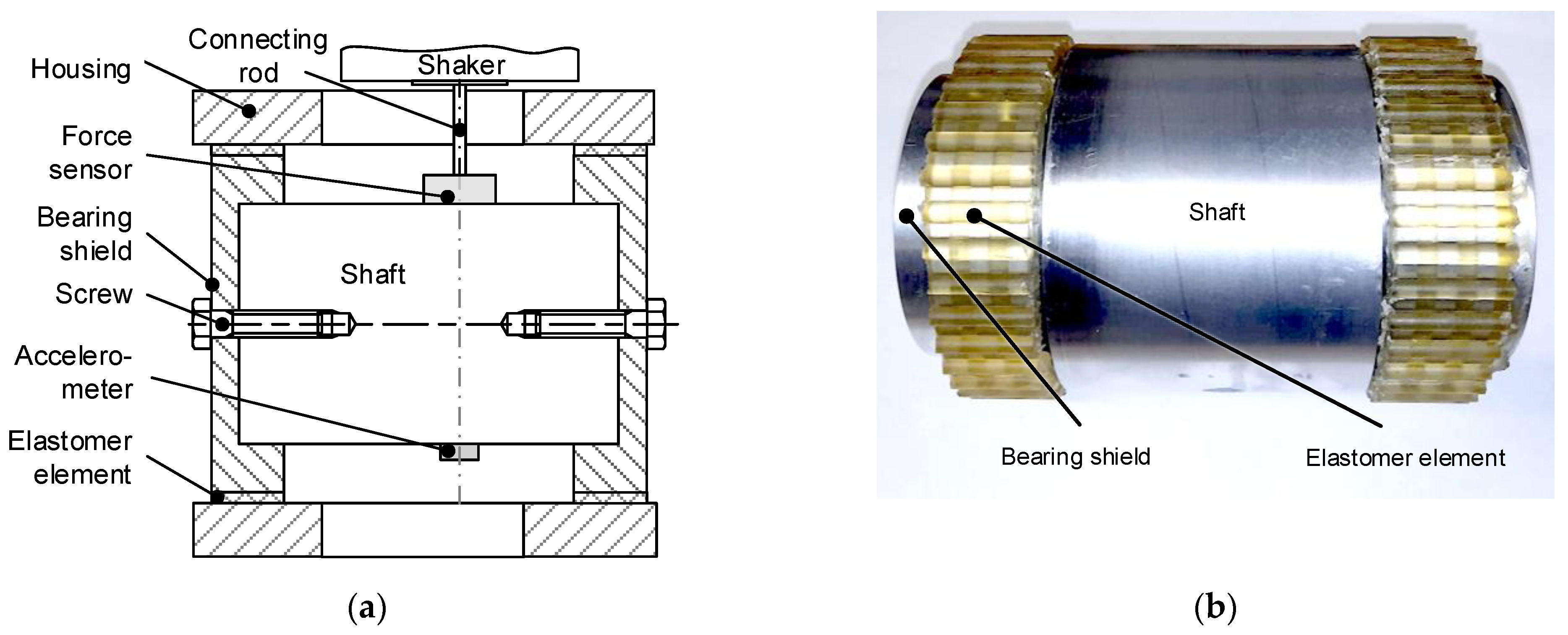
Approximate values for stiffness and damping of O-ring seal solutions may be found in the literature [32,33]. For accurate design and validation, empirical determination of suspension properties is required. Since stiffness and damping are both frequency dependent an approach is described that allows the determination of both values as a function of frequency. The approach is based on the half power bandwidth method. A solid shaft connects both bearing shields as illustrated in Figure 6a,b. There are no bearings included in this setup since the suspension stiffness is significantly lower than the stiffness of the bearings. Therefore, the overall stiffness is primarily determined by the resilient bearing seat. The resonance frequency of this test setup (and consequently the frequency at which the properties are determined) can be modified by changing the mass of the shaft connecting the bearing shields. An electro-mechanic shaker is used to excite the setup and an accelerometer measures the acceleration of the shaft.
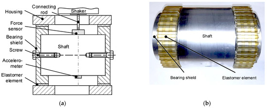
Figure 6.
(a) schematic diagram of the test system; (b) shaft and bearing shield assembly with cast elastomer structure.
The test system is shown in Figure 7a, the result of a measurement shown in Figure 7b. To determine stiffness and damping the resonance frequency fres must be determined.
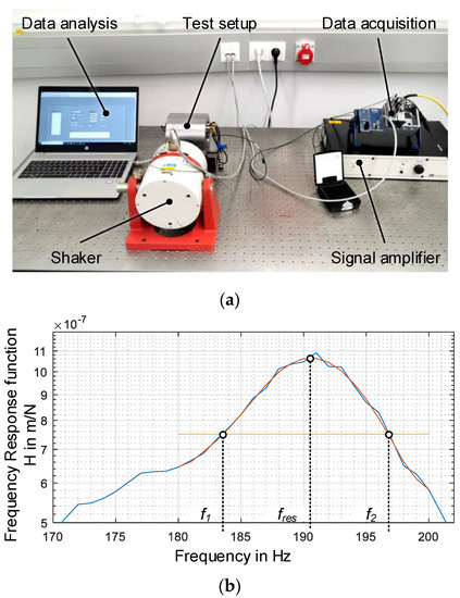
Figure 7.
(a) test setup for dynamic testing of resilient bearing suspensions; (b) frequency response function to determine stiffness and damping behavior.
The value of the frequency response function at the resonance peak is divided by 2 and the according frequencies f1 and f2 are calculated. Then, the damping ratio D can be calculated based on these values as stated in Equation (1).
Based on the simple model of a mass-spring-damper system (aka “linear oscillator”) the resonance frequency is determined as shown in Equation (2).
Applied to the results in Figure 7, the resilient support structure can be characterized by the values listed in Table 2.
Table 2.
Characteristic values of the resilient bearing suspension incorporating O-ring seals with a cord diameter of 2 mm.
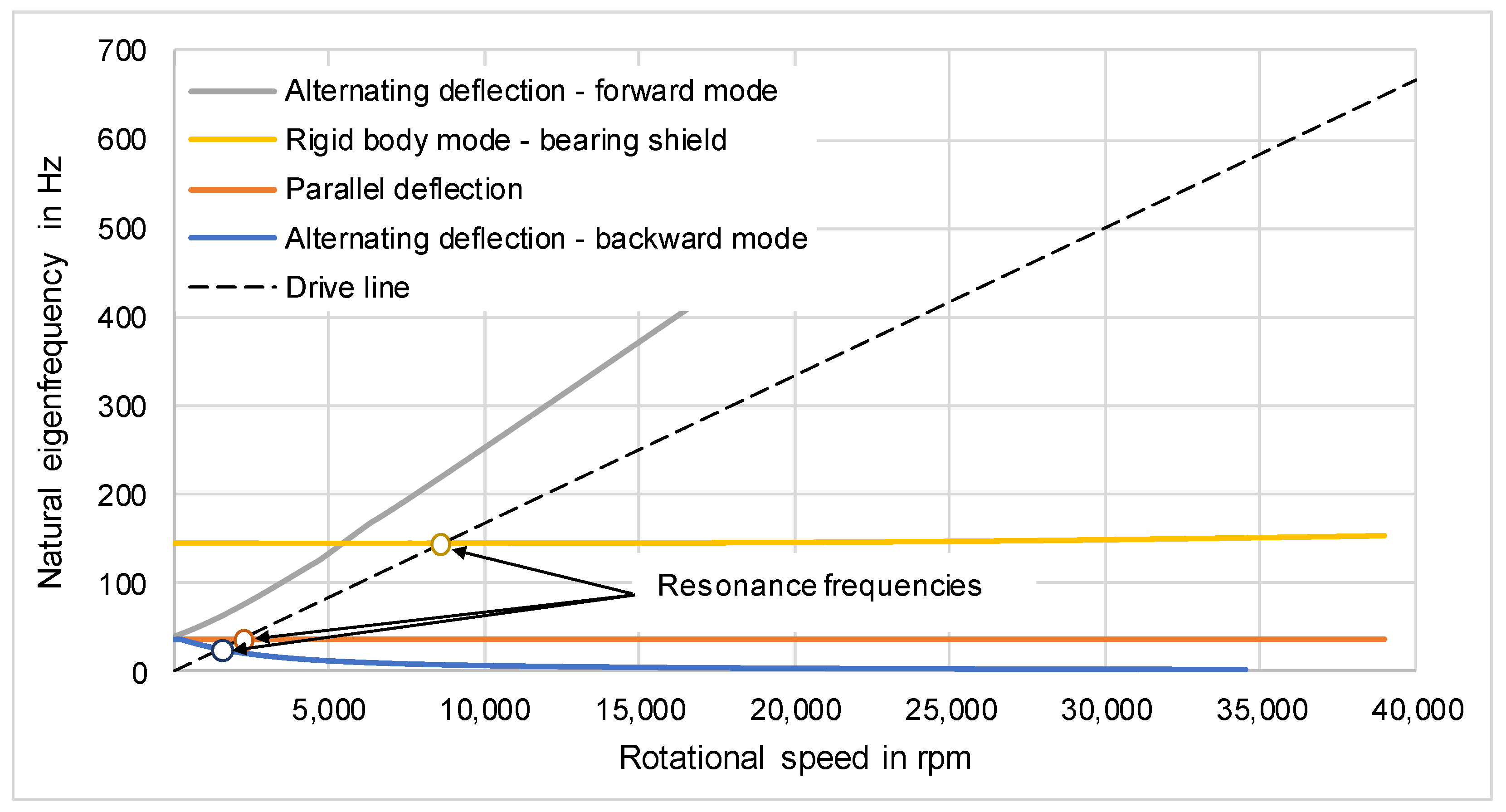
Based on a resilient suspension with a radial stiffness of 5 N/µm machine dynamics were simulated with results shown in Figure 8. The first two eigenfrequencies appear below 3000 rpm and therefore far from the operational speed range that starts at 10,000 rpm. The according eigenmodes are a parallel deflection of the entire shaft and a backward whirl mode that is made up of an alternating deflection of each shaft end.
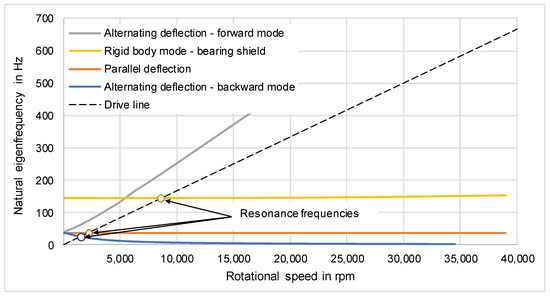
Figure 8.
Campbell plot of the rotor-bearing system with a resilient suspension stiffness of 5 N/µm Simulation conducted with MESYS Shaft (Version 07-2019, MESYS AG, Zürich, Switzerland).
The third eigenfrequency at approximately 8000 rpm is a rigid body mode of the bearing shield as illustrated in Figure 9. This eigenmode can occur due to:
Figure 9.
Rigid body mode of the bearing shield around 8000 rpm.
- the resilient mounting of the bearing shield in the housing
- the spring preload, which does not provide an end stop
- a low angular stiffness of the bearing on the shaft
This eigenfrequency depends on the rigidity of the resilient suspension against rotation and the mass of the bearing shield. By providing an increase in resilience and rotor mass this eigenfrequency can be decreased and therefore set to not interfere with the motor generator’s operational speed range.
3.2. Bearing Loads
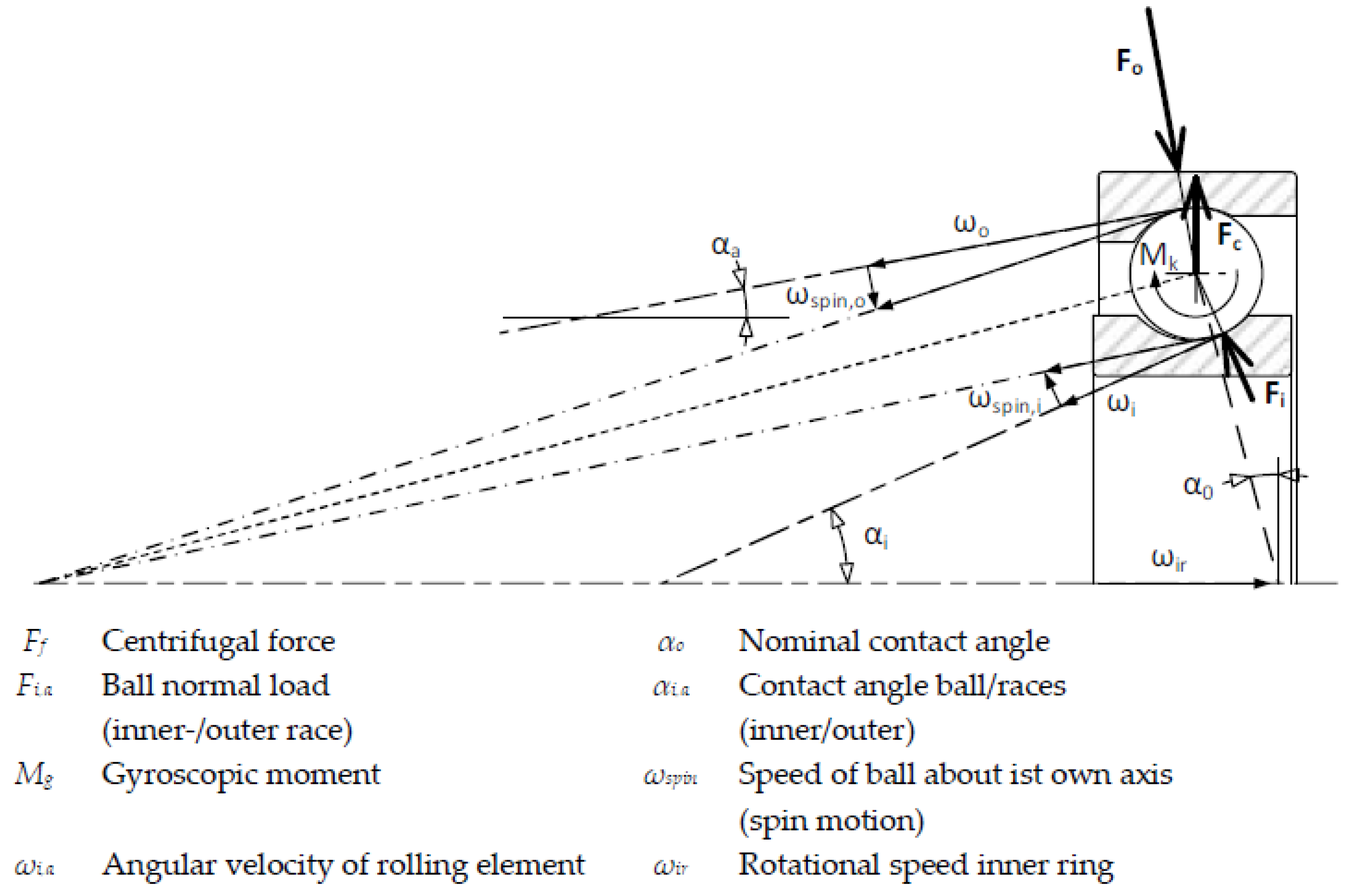
Bearing loads play a crucial role in system design for FESS regarding bearing kinematics as well as bearing life and torque loss. For that reason, bearing loads and optimization options that focus on the peripheral components will be analyzed in this section. Figure 10 shows the forces acting on a bearing ball of an angular contact spindle bearing. The ball normal forces Fo and Fi and the centrifugal force Fc on the rolling element must be in equilibrium. This results in different contact angles ai and ao between the rolling element and the inner/outer ring respectively during combined centrifugal and axial load, which is a decisive factor in bearing kinematics (see Section 3.2.3). Because of the contact angles in the bearings, even small axial loads lead to high ball normal forces, which determine bearing life (see Section 3.2.4). At the end of this section, these findings are applied to the FESS described in Section 2.4.
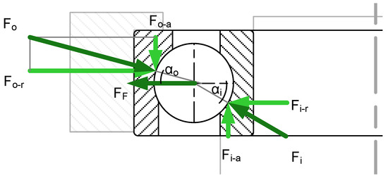
Figure 10.
Force situation inside an angular contact spindle bearing including centrifugal force.
3.2.1. Radial Bearing Loads
Predominantly machine dynamics have a significant influence on radial bearing loads. However, supercritical operation allows a minimization of external radial forces on the bearings compared to subcritical operation [4]. As a result, of supercritical operation, radial bearing loads depend mainly on suspension stiffness, a characteristic of the resilient bearing seat. In the case of the rotor described in Section 2.4, the radial bearing load amounts to approximately 4 N (Based on a suspension stiffness of 5 N/µm and a balancing quality of G2.5 at maximum rotational speed of 30,000 rpm).
Resilient structures made out of elastomer also introduce the necessary damping to the system. As a result, the required resonance passes through for supercritical operation can be accomplished easily without the risk of damage due to excessive vibration levels.
For subcritical operation, high balance quality is even more important as it directly influences radial bearing loads at any given rotor speed. While bearing loads in subcritical rotor operation are usually a lot higher than in the case of supercritical operation implying a resilient bearing seat, loads can indeed be mitigated by accurate dynamic rotor balancing [33].
3.2.2. Axial Bearing Loads
Axial bearing loads in FESS are caused by two sources:
- (a)
- The rotor weight
- (b)
- (Intentional) axial bearing preload
Bearing loads caused by rotor weight may be reduced by a lifting magnet, provided the rotor incorporates a ferromagnetic material.
Bearing preload on the other hand shall not be fully avoided, but it can be kept as low as required using spring preloaded bearing setups. Both will be analyzed in the paragraphs below.
- (a)
- Magnetic Rotor Weight Compensation
For magnetic rotor weight compensation permanent magnets as well as electromagnets are suitable. Both offer specific advantages as summarized in Table 3. When magnetic weight compensation is to be implemented, two prerequisites must be fulfilled. First, at least certain parts of the rotor must be made of ferromagnetic material or a magnet. Second, the rotational axis must be vertical. Usually, both prerequisites can be fulfilled easily.
Table 3.
Comparison of electromagnetic and permanent magnetic weight compensation setup.
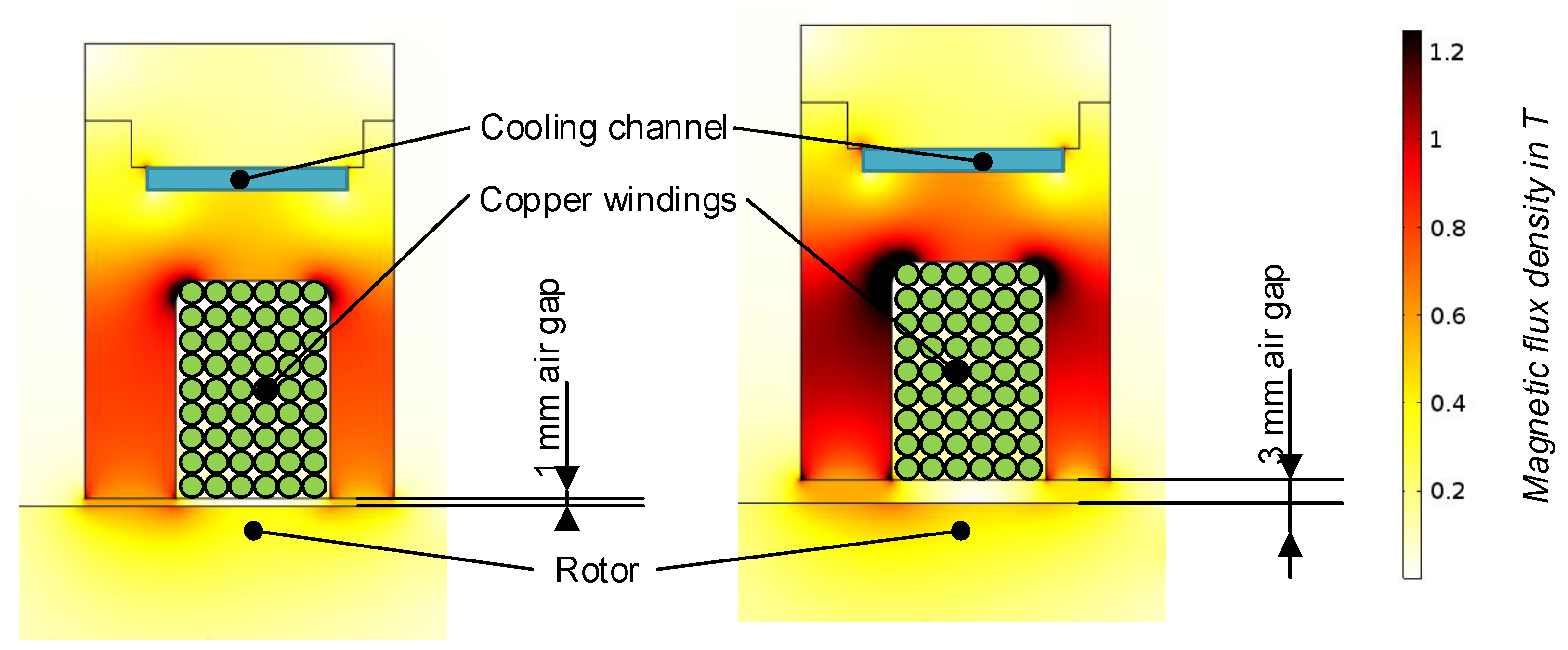
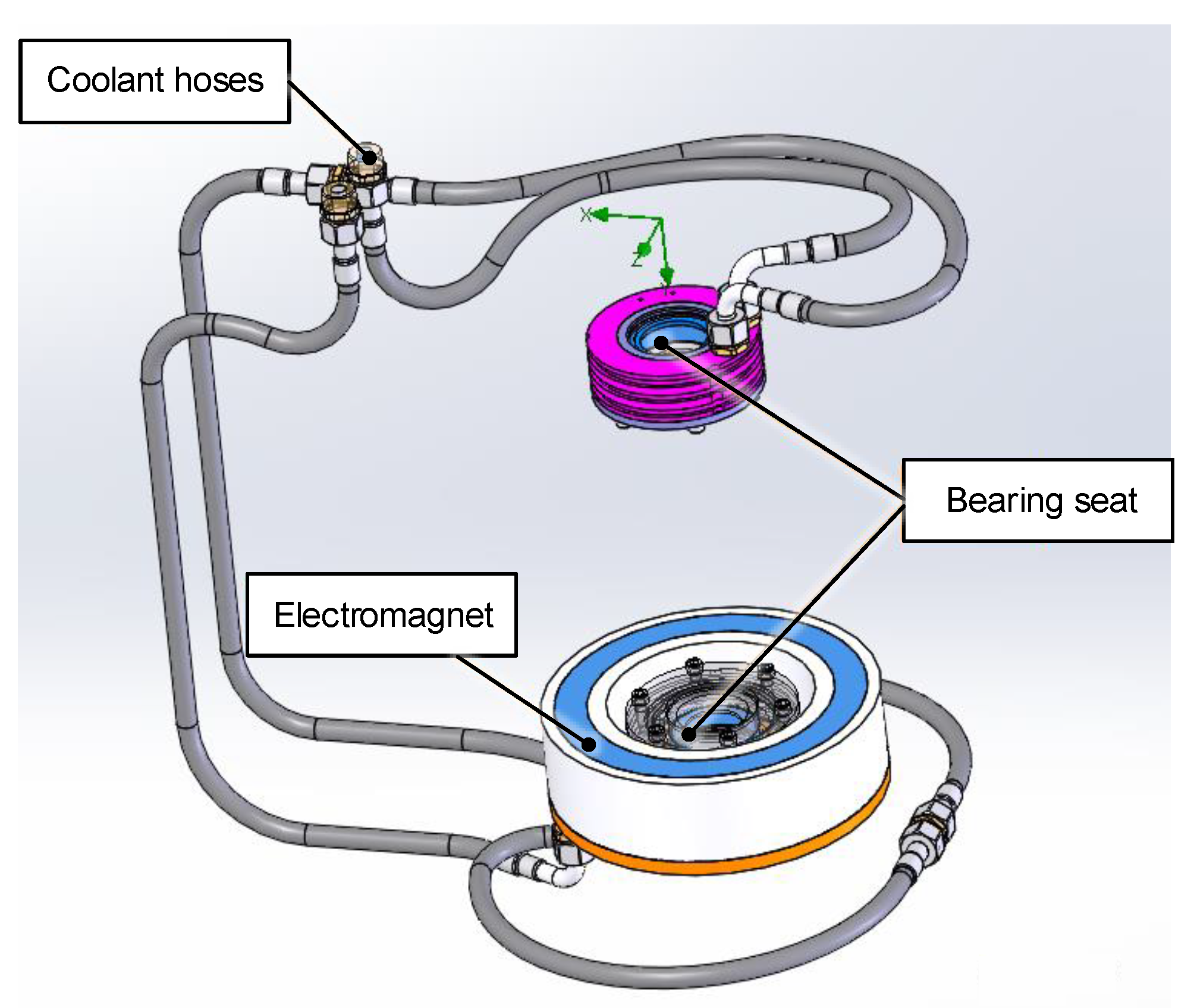
In this section, a rotor weight compensation setup using an electromagnet will be analyzed. A similar procedure may be used for the design of permanent-magnetic weight compensation as well [31]. The degree of weight compensation may reach up to 100% of the total rotor weight, but it must be kept in mind that mechanical bearings require minimum loading to ensure proper kinematics (see Section 3.2.3). The design of the electromagnet for this specific use-case was performed with the help of magnetic flux simulations in order to investigate the influence of variations in air gap. Figure 11 shows such a simulation used during the design phase of an electromagnet. In the displayed picture, the rotational axis of the rotor is aligned vertically. Therefore, the left leg of the U-shaped magnet must be bigger than the right one in order to realize similar surface area pointing at the rotor. There is a cooling channel included in the lifting magnet body for rejection of heat generated by ohmic losses in the coils. This is necessary because of the absence of convective cooling as a result of the low-pressure atmosphere.
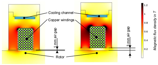
Figure 11.
Design and magnetic flux density distribution in the electromagnet at different air gaps for a weight compensation of 1350 N. Simulation conducted with Comsol Multiphysics 5.6.
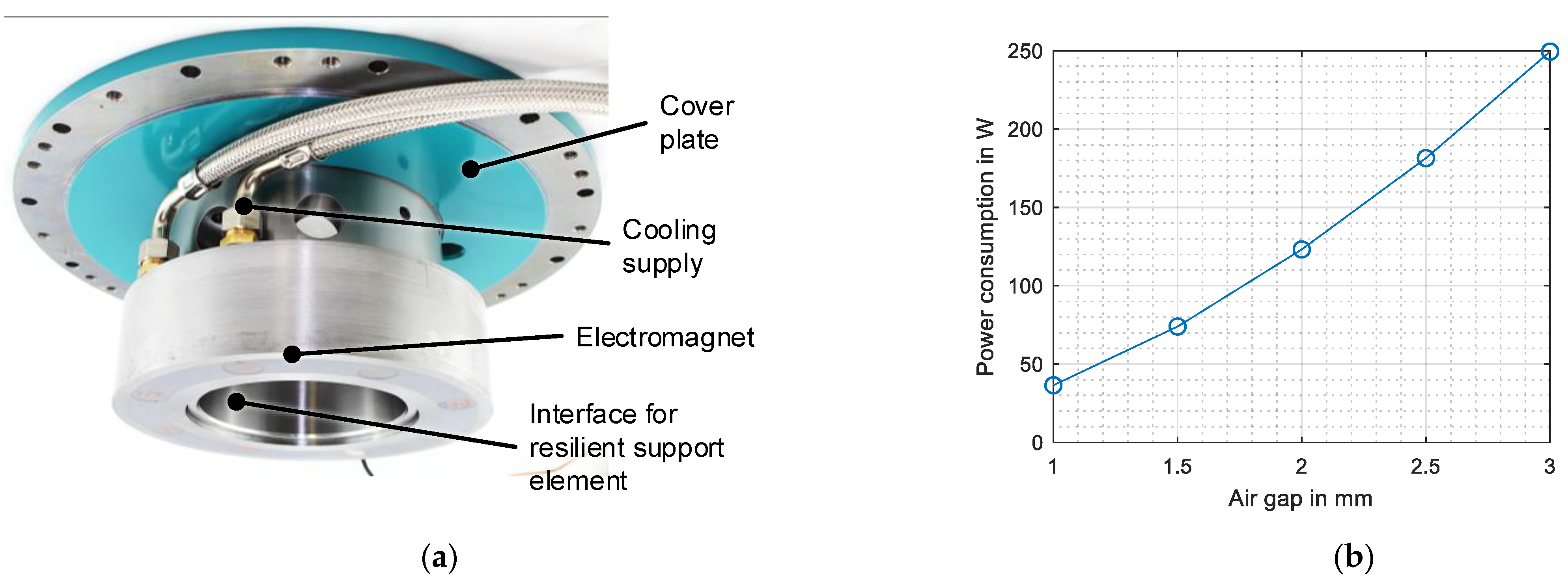
In Figure 12a the electromagnet assembled with the cover plate is shown. The empty spaces/gaps between the copper windings of the magnet are filled with a special resin that offers very high thermal conductivity to allow better heat rejection to the coolant channel. During operation, the magnet’s power consumption is a crucial operating parameter regarding potential overheating, since the generated heat must be dissipated through the cooling channel. The thermal simulation of the electromagnet is presented in Section 4. Figure 12b shows simulation results for required power during operation at different air gaps. Required power increases from 35 W at 1 mm to 240 W at 3 mm air gap. The simulation assumes a targeted lifting force of 1350 N, which corresponds to 95% rotor weight.

Figure 12.
(a) Electric magnet assembled with the cover plate; (b) Power requirement as a function of air gap for a rotor weight compensation of 1350 N.
- (b)
- Axial Bearing Preloading
To achieve constant axial bearing preload within the entire operational speed range a spring preloaded configuration is used. The configuration in X-arrangement minimizes necessary machining on the shaft, because no threads or additional components are required for assembly with the bearings. Therefore, high initial rotor balancing quality can be reached. Two main setups remain after the described preselection of one of the concepts illustrated in Figure 13:
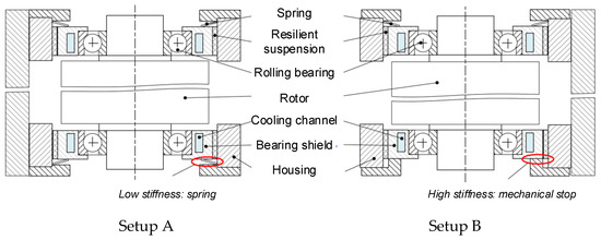
Figure 13.
Two concepts regarding axial spring preload of bearings in X-arrangement.
- Setup A consists of coil springs attached on each bearing shield. This configuration ensures constant, precisely adjustable axial preload. Nevertheless, this configuration is very prone to vibrations and attention must be paid to axial oscillations as a result of potential external axial excitations. These excitations may be caused by overall system machine dynamics or the naturally instable characteristics of an attracting magnetic weight compensation.
- In Setup B a spring presses the opposite bearing shield against an end-stop. This design is very robust and simple, but it must be assured that rotor weight compensation does not exceed 100% and relieve the bearing pressed against the end-stop as this state would lead to issues regarding bearing kinematics as discussed in Section 3.2.3.
Both setups are suitable for the desired application in FESS and in combination with magnetic weight compensation very low axial bearing loads can be achieved. For that reason, bearing kinematics must be considered in order to guarantee valid operating conditions.
3.2.3. Bearing Kinematics
Two aspects must be carefully considered regarding bearing kinematics as a result of minimized bearing loads as discussed in the previous sections. These aspects regarding kinematics are the minimum bearing load limit and the spin-/roll ratio (SRR). Both depend strongly on inner bearing geometry as well as external loading and will be dealt with in the following.
- Minimum Load Limit
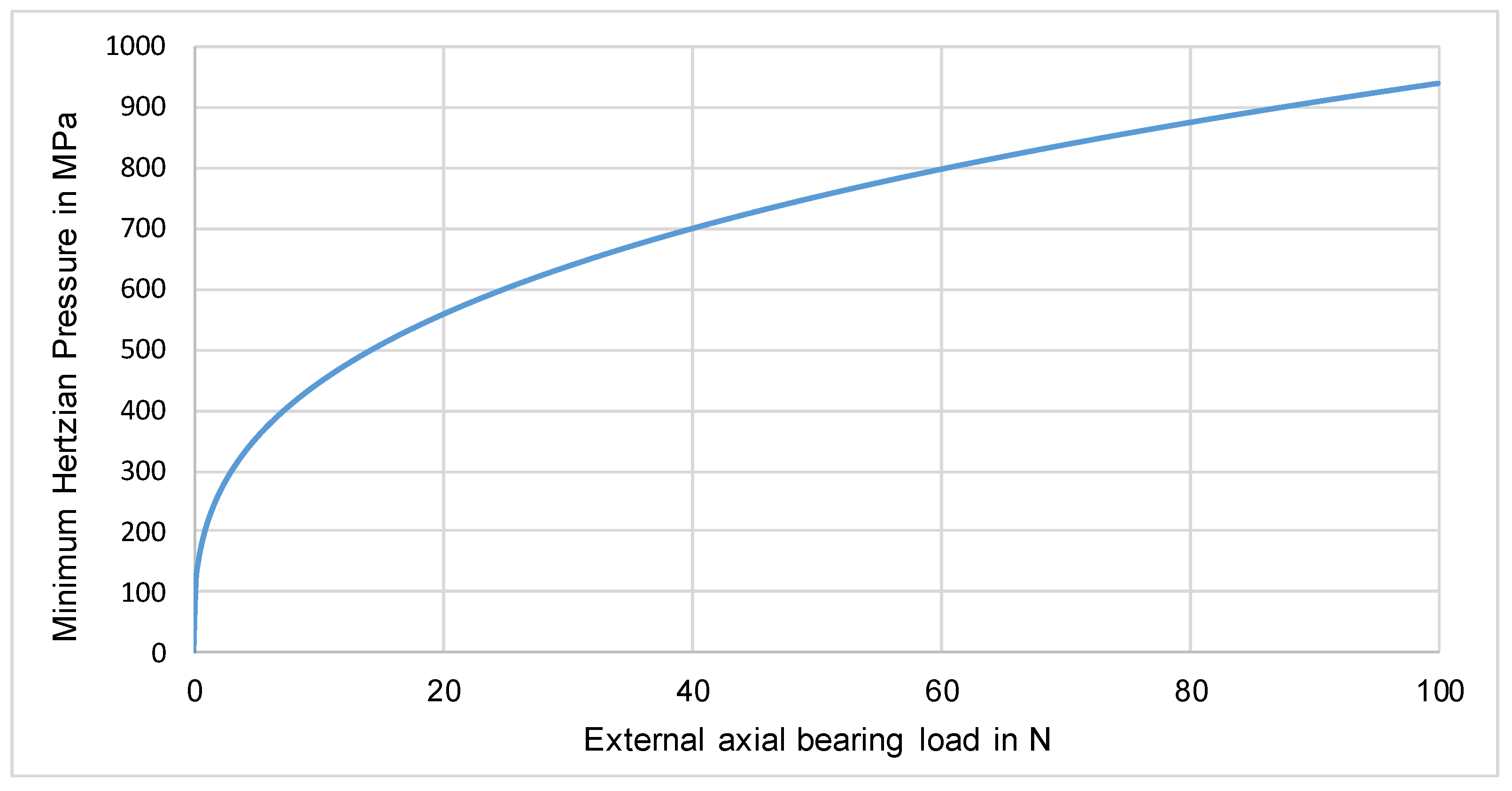
Every rolling element must be in contact with both races of the bearing at all times and maintain a certain pressure. Otherwise, unwanted sliding between rolling element and races may occur and cause damage to the balls and races. To the knowledge of the authors, there are no explicit design guidelines regarding minimally required contact pressure documented in publicly available literature. Only a recommendation for minimum loading is defined in [34,35] as 1% of the static load limit. This requirement results in a pressure of about 600 MPa in the rolling contact in the case of an angular spindle bearing with a bore diameter of 25 mm [36]. However, in this recommendation, system boundary conditions and properties are not considered. Therefore 600 MPa is likely to be a conservative choice.
Even small forces cause high Hertzian Pressure in the bearing as a result of point contact between rolling elements and bearing races. This is illustrated in Figure 14, considering a hybrid spindle bearing with a bore diameter of 25 mm and a contact angle of 15°. In this case, an external axial bearing load of 1 N causes a Hertzian Pressure of approximately 200 MPa. Within this study no external radial loads are considered.
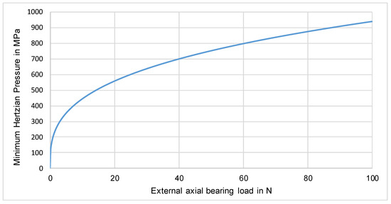
Figure 14.
Minimum Hertzian Pressure in an angular contact spindle bearing with a bore diameter of 25 mm under solely axial load–Simulation conducted with MESYS Shaft (Version 07-2019, MESYS AG, Zürich).
- Spin-to-Roll Ratio
In bearings with a contact angle a further aspect of bearing kinematics (SRR) must be considered to be well. A contact angle occurs not only in angular contact type bearings, but also in deep groove ball bearings that are subject to external axial loading. The SRR is defined as the ratio between the spinning and the rolling motion of the bearing ball relative to the races. If a certain limit is exceeded a decrease in bearing life may occur. Limits defined in the literature range between 0.25 and 0.5 [37,38]. Investigations have shown that the spinning motion occurs mostly between rolling element and either inner or outer race [39]. At low and moderate speed, the rolling element is generally guided at the inner ring due to tighter osculation between rolling element and race. In high-speed applications it is usually assumed that the ball is guided on the outer race and the spinning motion occurs on the inner ring [40]. There is no general definition of what is considered a high-speed application in the context of the SRR to the knowledge of the author. Furthermore, inner bearing geometry strongly influences inner bearing kinematics and generally valid statements can hardly be made.
In most cases, inner bearing geometry cannot be modified in order to influence the SRR that occurs during operation, unless the bearing manufacturer itself is willing to do so.
Figure 15 illustrates inner bearing kinematics and loading situation in an angular contact ball bearing. Spinning motion increases with increasing difference in contact angle between rolling element and inner/outer race. This increase in difference is caused by centrifugal forces on the rolling elements. Therefore, the SRR increases with increasing rotational speed of the bearing. The difference in contact angle decreases with increasing external axial bearing load.
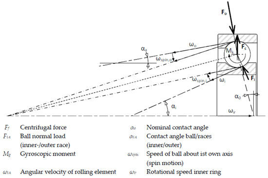
Figure 15.
Spin-/Roll ratio in an angular contact ball bearing at high speed.
According to [36], the SRR consequently decreases with:
- An increase in external axial bearing load
- Decreasing rotational speed
- The use of ceramic rolling elements (hybrid bearings—this effect may be attributed to the higher modulous of elasticity of ceramic (e.g., Si3N4) rolling elements and the lower density compared to steel, resulting in reduced centripetal forces).
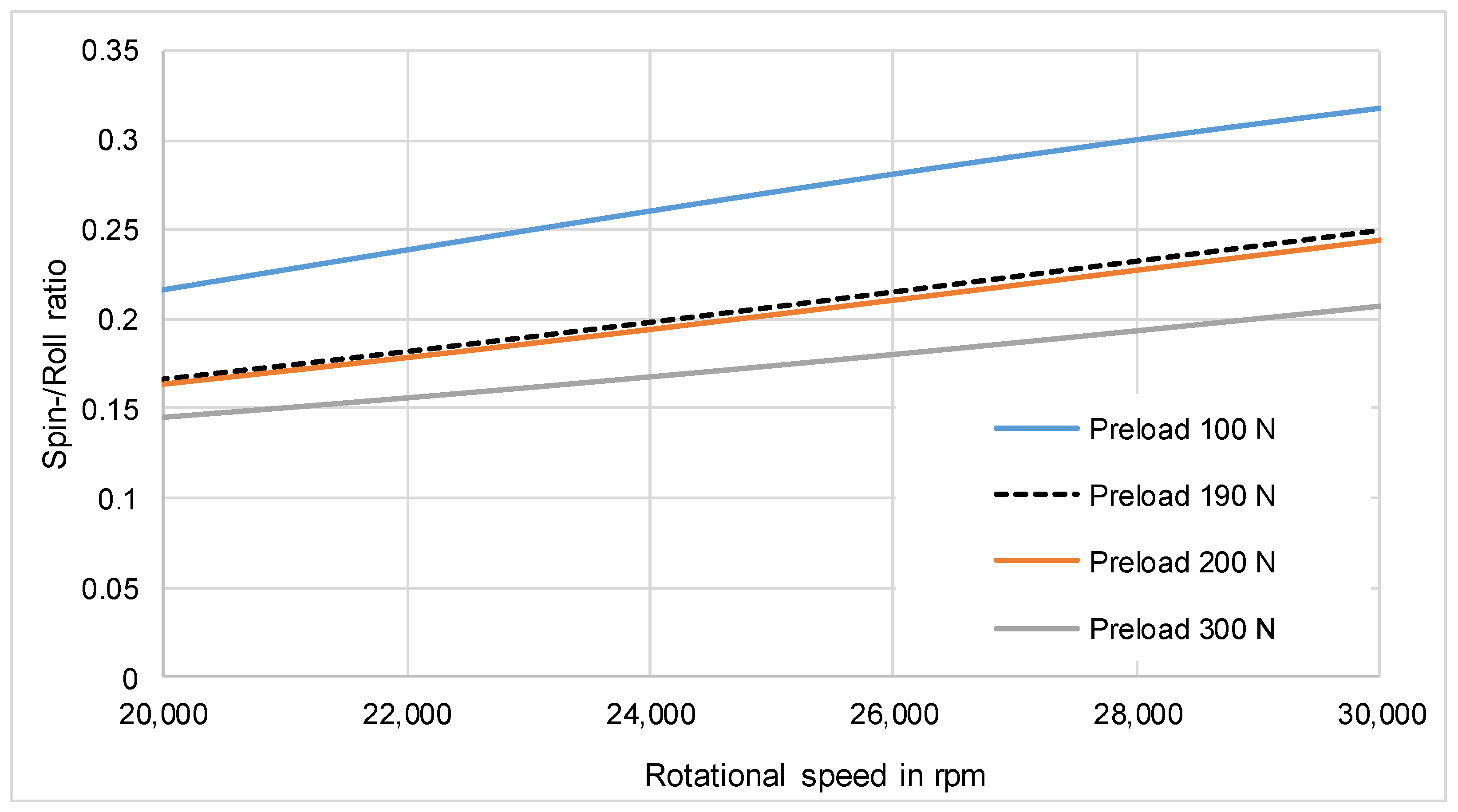
In this case, the hybrid spindle bearing myonic-SRD 30550VA with a bore diameter of 30 mm in X-arrangement was used Figure 16 shows the corresponding SRR as a function of rotational speed for different axial bearing preloads. It is assumed that the entire spinning motion takes place on the inner ring and external radial loads are negligible. As discussed previously, the SRR increases with speed and decreases with increasing preload. The dotted line represents the preload that leads to a value of 0.25 at maximum speed for the use-case described in Section 2.
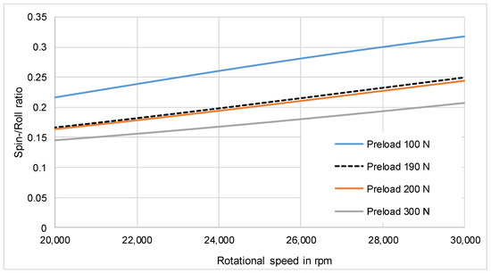
Figure 16.
Spin-/Roll ratio of an axially spring preloaded angular contact spindle bearing between 20,000 rpm and 30,000 rpm—Simulation conducted with MESYS Shaft (Version 07-2019, MESYS AG, Zürich).
3.2.4. Bearing Fatigue Limit
Based on the boundary and environmental conditions in FESS, bearings can reach long term fatigue limit. The main reasons for that are very clean environmental conditions as a result of the operation under vacuum and very low external bearing loads as described in the previous sections. In the literature, different fatigue load limits are defined for rolling element bearings. Permissible Hertzian Pressure levels range between 1500 MPa and 2500 MPa [37]. In the upcoming analysis, the lowest limit of 1500 MPa is chosen in order to take a certain safety consideration into account.
Figure 17 shows different combinations of axial bearing preload, degree of weight compensation and the resulting maximum Hertzian Pressure during operation at maximum speed. The lower the degree of weight compensation, the lower the bearing preload must be in order to remain below 1500 MPa.
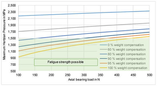
Figure 17.
Maximum Hertzian Pressure as a function of axial bearing load for different degrees of weight compensation for a system with two myonic–SRD 30550VA bearings mounted in a resilient bearing suspension–Simulation conducted with MESYS Shaft (Version 07-2019, MESYS AG, Zürich).
3.2.5. Adjustment of Preload and Weight Compensation
The following considerations are based on a concept consisting of two myonic SRD 30550VA bearings. Bearing size was chosen due to design considerations regarding stiffness and stresses in the rotor shaft during operation. By decreasing bearing size torque loss and heat generation may be optimized, but this aspect is not considered in this publication. Bearing size does not influence the described design procedure or validation methods.
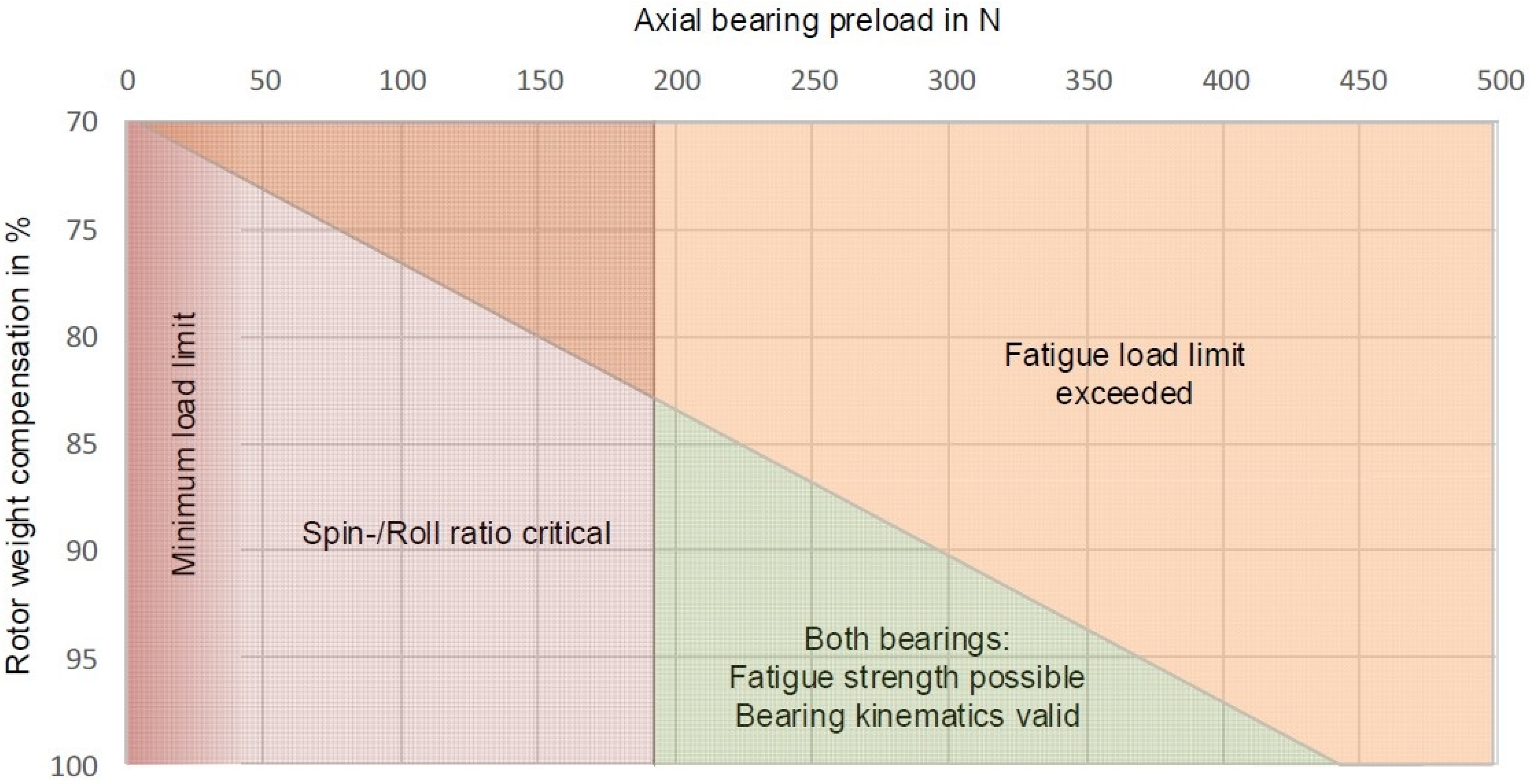
The lower limit for axial bearing preload is defined by bearing kinematics as discussed in Section 3.2.3 and the upper limit for bearing preload depends on the fatigue load limit as analyzed in Section 3.2.4. Combined with the degree of weight compensation there are combinations of preload and weight compensation that ensure valid bearing kinematics as well as component fatigue limit. This is visualized in Figure 18. It must be noted that bearing kinematics is considered for the bearing that experiences the lower load (top bearing in Figure 3), fatigue limit is the decisive factor for the bearing that experiences the higher load (bottom bearing in Figure 3). In both cases rotor weight compensation levels are assumed to be below 100%. In the case defined in Section 2, the weight compensation must reach at least 83% to fulfill fatigue load requirements. At 100% weight compensation bearing preload may lie between 190 N and 440 N. Final values for preload and weight compensation may depend on other aspects such as system design or thermal management, as analyzed in the next section.
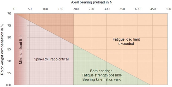
Figure 18.
Rotor weight compensation and bearing preload for optimized bearing design.
4. Thermal Management and Lubrication
Two decisive properties mainly determine the thermal behavior of the bearing system:
- Bearing thermal conductance
- Bearing torque loss
The thermal conductance of rolling bearings is still subject to research at the moment and results related to this specific project/bearing system will be presented in an upcoming publication. Nevertheless, there are some publications available that deal with this topic and describe methods to determine this property empirically and also provide measurement results related to the thermal conductance [41,42].
Bearing power loss will be discussed briefly in the next section. A general overview regarding both thermal properties and the influence of major aspects is summarized in Table 4.
Table 4.
Effect of main operating conditions on thermal properties of the bearing system.
4.1. Thermal Properties of the Bearing System
There are some analytical methods that allow an estimation of bearing power loss under different operating conditions [34,35]. Unfortunately, these methods are not sufficiently accurate when applied to the analyses of low-loss FESS bearing systems. The reason for that lies in the operating conditions in FESS that differ significantly from most common use cases found in general engineering and machinery. Input values for the calculation of bearing friction for spindle bearings are not documented in publicly available literature. Table 5 compares the conditions in the bearing system defined in Section 2 with a general case based on the conditions defined for the thermal reference speed.
Table 5.
Comparison of basic conditions in FESS and what the thermal reference speed is based on.
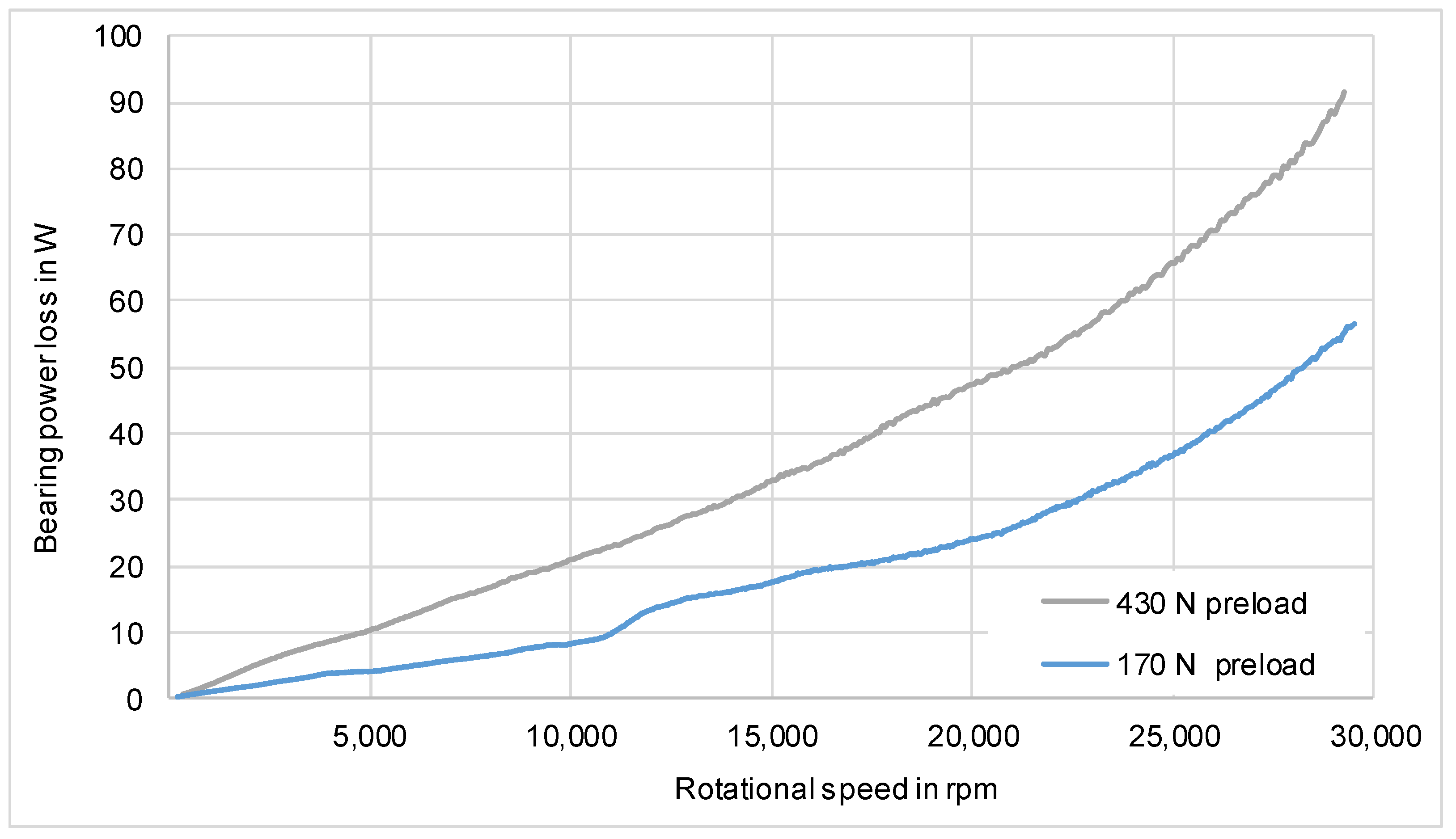
Bearing friction of the system described in Section 2 was determined empirically under a variation of axial preload. The test setup for the measurement of bearing power loss is described in [31] and results are shown in Figure 19.
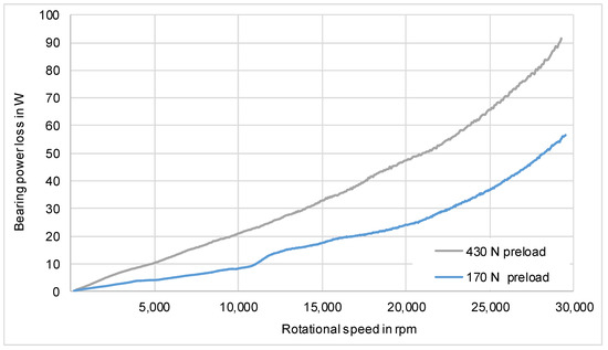
Figure 19.
Bearing power loss under different axial preloads as a function of rotational speed for a system consisting of two myonic SRD 30550VA bearings and Klüberquiet BQR 78/102 grease.
As expected, bearing power loss increases with rotational speed and axial preload. All graphs represent the total power loss in the test setup that consists of two bearings and potential other sources such as remaining windage loss or energy dissipation via damping in the resilient bearing support. This means that these graphs indicate the maximum bearing friction possible within the measurement for the investigated hybrid spindle bearing.
Compared to the results of Jiang [24], the bearing system in the publication at hand shows a reduced bearing power loss at 20,000 rpm of 90–95%, depending on preload. Jiang used a FESS with C7002-C-T-P4S type bearings and an integrated motor/generator topology. It must be mentioned that Jiang did not focus on a reduction of bearing power loss, but on machine dynamics behavior and simulation.
To reject the waste heat generated by the bearings (and also reject potential rotor heat either induced by the motor-generator or by windage losses on the outer circumference of the rotor), the bearing seat is equipped with a coolant channel. Figure 20 shows the simulation setup of the cooing circuit, covering both mechanical bearings and the electric lifting magnet.
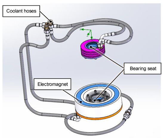
Figure 20.
Basic hydraulic scheme for CFD simulation of the bearing system and the electric magnet. (Setup flipped upside down with lifting magnet shown at the bottom).
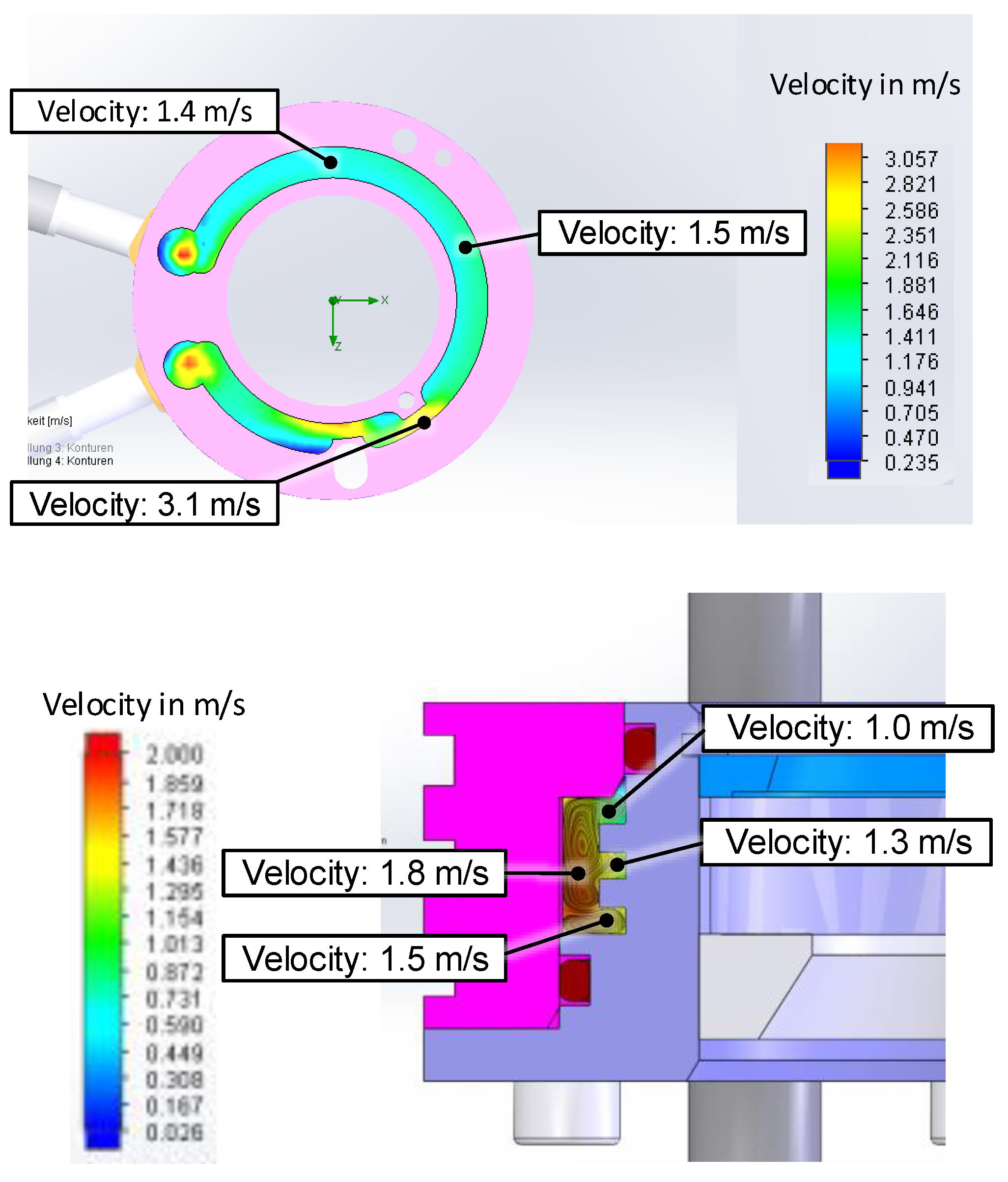
Heat transfer between the coolant and the bearing shield strongly depends on fluid’s flow regime, such as Reynold’s number and degree of turbulence depending on mass flow. In the presented case, a computational fluid dynamics (CFD) simulation was carried out in order to analyze different geometries of the cooling channel and identify an optimized geometry. The optimization criteria include maximized heat transfer at lowest pressure drop and minimal required mass flow. It must be noted that, depending on the actual FESS topology, not only bearing frictional losses but also ohmic/eddy current losses of the electric machine and aerodynamic dissipation (windage losses) need to be rejected via the bearing’s cooling circuit. Figure 21 shows a simulation result for the fluid flow and temperature field in the cooling channel of the bearing seat.

Figure 21.
Thermal simulation of the bearing seat cooling channel. Simulation conducted with ANSYS fluent 2021 R1.
Counterintuitively, even though bearing friction increases significantly with preload, higher preload may lead to a decrease in maximum system temperature in some applications. This phenomenon can be explained by the increase of thermal conductance with increasing axial bearing load and rotational speed as shown in Figure 22. Bearing thermal conductance was determined by the use of the test setup described in [41].
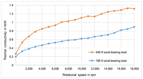
Figure 22.
Thermal conductance of an SKF 71908 CEGA/HCP4A bearing grease lubricated with SKF LGLT2 as a function of rotational speed for two different axial loads.
For instance, in electric motors it is crucial that generated heat in the rotor can be discharged to prevent overheating. When such a motor is operated under vacuum, convective cooling is negligible. If the bearings are grease lubricated and no oil cooling concept is implemented, conduction through the bearings remains as the major cooling path to discharge generated heat from the rotor. In that case bearing power loss may be less crucial for system temperatures than thermal conductance of the bearings. Such a case is briefly summarized in Table 6 for the electric motor described in Section 2.4. Maximum bearing temperature under steady state condition decreases with increasing bearing preload. The effect of rising bearing power loss is overcompensated by the increase in thermal conductance regarding system temperature. The presented result is based on the load cycle shown in Figure 4. To identify such effects, thermal properties of the bearings are crucial and must be determined to conduct required simulations [36].
Table 6.
Steady state maximum bearing temperatures in an electric motor for FESS.
4.2. Lubrication
The correct selection of a suitable lubricant does not only influence service life and safety of FESS (bearing failure may cause bearing and potentially dangerous system failure [43]), but it goes hand in hand with proper thermal management of the system.
The key parameters for selecting a suitable lubricant are bearing temperature in combination with ambient pressure. Bearing temperature can be determined with the help of a thermal simulation taking into account the load cycle and transient effects. The ambient pressure (usually in the range of 1 to 10−5 mbar) may cause outgassing of the lubricant, resulting not only in poor vacuum quality, but also a detrimental effect on lubricant life. The vapor pressure of a lubricant is mainly determined by the used base oil, which can be seen in Table 7 for three different greases commonly used in vacuum environment.
Table 7.
Vapor pressure of different vacuum suitable lubricants at different temperatures.
Given typical operating conditions in FESS, a temperature of 125 °C and a pressure of 10−4 mbar (0.01 Pa), only few lubricants work properly under these conditions. Besides the aspect of outgassing, the operating temperatures are limited by other bearing properties, such as:
- Maximum permissible temperature of the cage: This part is usually made from polyamide and limited at around 100–120 °C or PEEK for higher temperatures up to 150 °C [37].
- Service life of the lubricant: When operated above the so-called continuous limit temperature), the service life of the lubricant is reduced exponentially [28].
The so-called reference speed factor (a.k.a. n*dm value) considers the operating-related speed of the bearing and represents an indicator regarding maximum speed capability. It is calculated as the product of the bearing pitch diameter dm and the rotational speed of the inner ring n. Usually, this factor is used to estimate the suitability of a lubrication concept in the context of bearing speed. The higher the n*dm value, the more demanding the operating conditions become in terms of high-speed operation. The n*dm can be reduced by either reducing rotational speed, or bearing diameter, whereas the second option is usually the only viable one in the case of FESS. However, even if bearing loads are mitigated according to the measures described in Section 3.2, the bearing diameter cannot be any smaller than the minimum required shaft diameter. This shaft diameter must be designed in accordance with rotor dynamics (potential resonance pass-through) and strength of material considerations.
In general, the cost of lubrication increases with higher requirements, as can be concluded from Table 8. LGLT 2 represents a commonly used grease for high-speed applications. Even though it is not intended to be operated in low pressure environment, it was used by the authors at pressures down to 10−2 mbar.
Table 8.
Cost comparison of two greases suitable for FESS application.
5. Final System Specifications
An overview of the final rotor bearing system without CFRP rims on the rotor is given in Figure 23. Table 9 summarizes system specifications of the described FESS and the bearing system that is used in this storage.

Figure 23.
Rotor-bearing assembly of the flywheel.
Table 9.
Main Characteristics of the described FESS.
A bearing preload of 300 N was chosen, in combination with 95% of the rotor weight compensated by the magnet the bearings can reach component fatigue limit. Because of an air gap of 1 mm the electromagnet requires approximately 45 W during operation. Cooling channels prevent the magnet from overheating. Thermometers and accelerometers are integrated in the setup for monitoring purpose during operation.
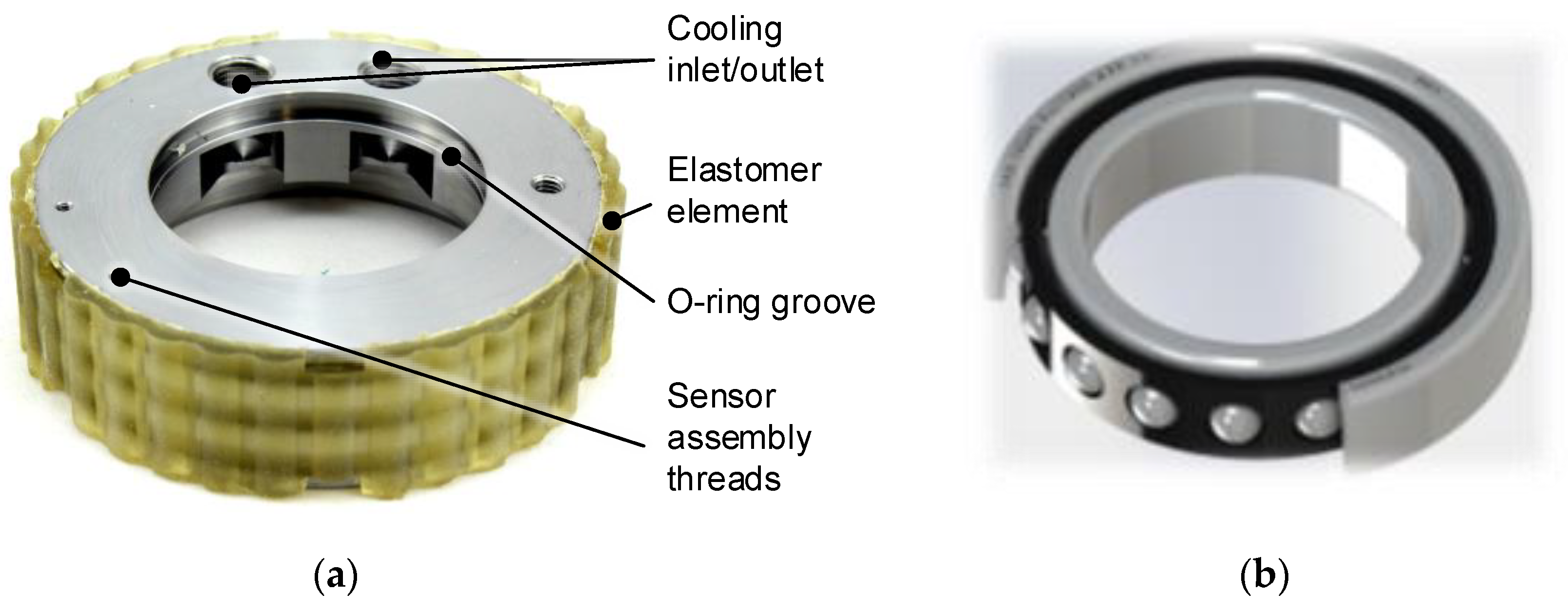
Based on the design and optimization procedure described in this publication, the overall bearing system was designed. The outer part of the developed bearing shield with the elastomer element and the bearing used in this assembly are shown in Figure 24. A cooling channel in the bearing shield is required because of the low thermal conductivity of the elastomer element.
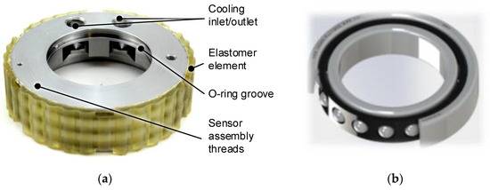
Figure 24.
(a) Part of the bearing shield; (b) hybrid spindle bearing myonic SRD 30550VA with a bore diameter of 30 mm and a contact angle of 15° used in the developed bearing system.
6. Summary and Conclusions
In this publication, a method to design and characterize mechanical bearing systems for flywheel energy storage systems (FESS) is presented. Even though values for FESS bearing system torque loss can rarely be found in the literature, a significant loss reduction by around 90% was achieved compared to some systems such as [24].
In terms of cost reduction, there is no definitive and quantitative cost state of the art that can be compared to the achievements presented in this paper. The cost reduction measures can be summarized as follows:
- The use of rolling element bearings is significantly cheaper than active magnetic bearings.
- -
- AMBs may be advantageous in terms of service life and offer adjustable stiffness and damping, which is beneficial in terms of achieving reliable machine dynamics behavior [48].
- -
- Drawbacks because of low damping in REBs are compensated for by the introduction of an elastomer suspension, which provides external (viscous) damping to the bearing system. Compared to widely used squeeze film dampers [24], elastomer suspension concepts are advantageous in terms of cost.
- -
- Limited service life of REBs can be improved through different measures, such as magnetic weight compensation and supercritical machine dynamics operation strategy. Both aspects are dealt with in Section 3.
- The use of easy to manufacture passive vibration isolation measures (cast elastomer structures using 3-D printed casts) is cheaper than active measures such as squeeze film dampers or piezo actuators.
- The resilient bearing seat allows looser tolerancing (and super-critical rotor operation) resulting in reduced manufacturing cost.
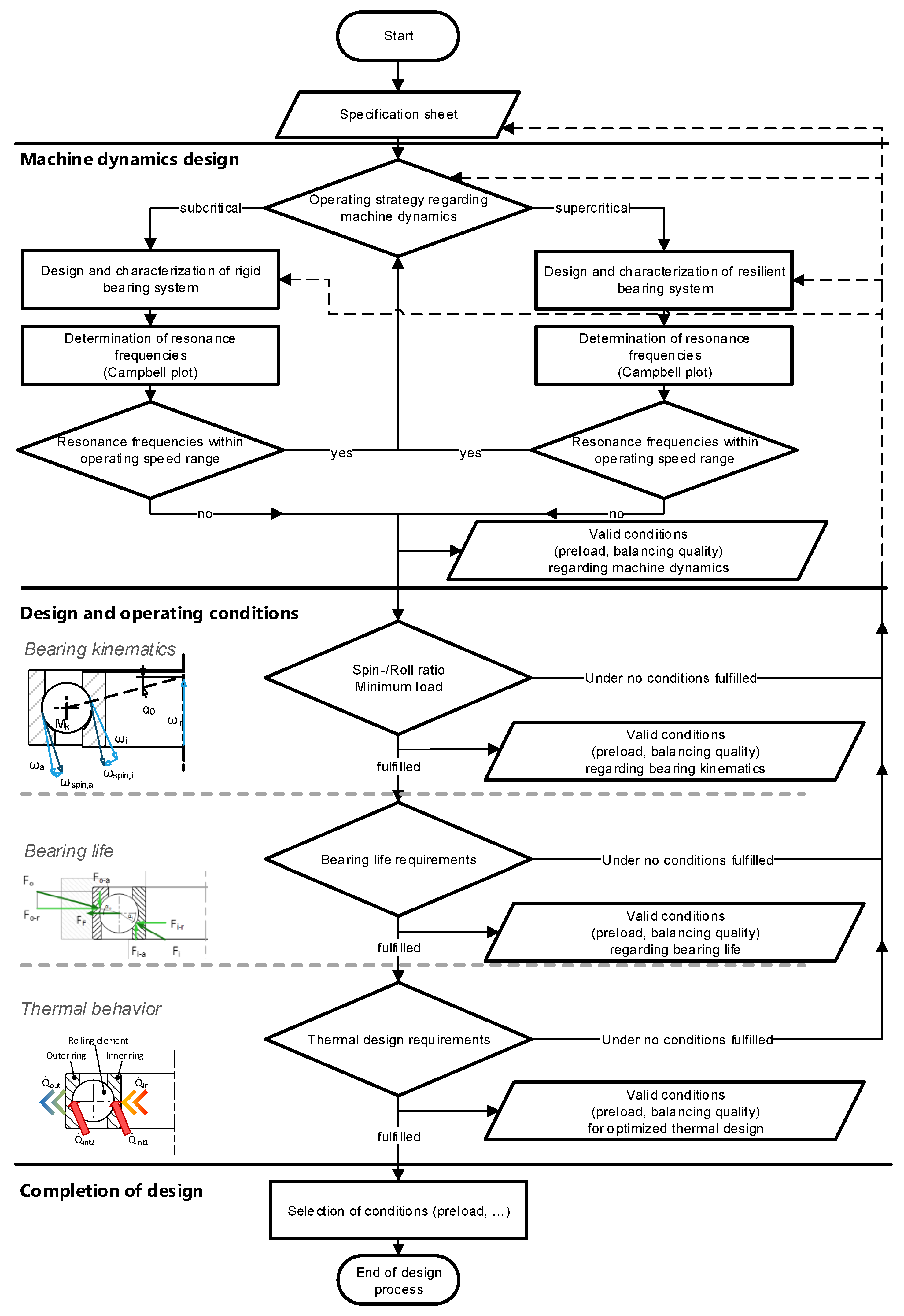
Furthermore, a detailed methodological guideline for FESS rolling element bearing design is published for the first time within this paper. Due to the highly demanding operating conditions present in FESS, special bearing system properties must be considered during the design process. This design process is summarized in Figure 25, giving a generally valid guideline for FESS incorporating roller bearings.
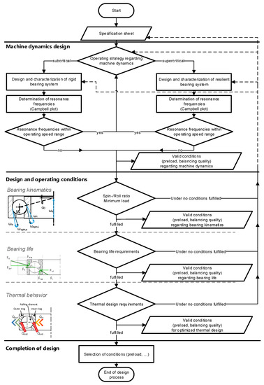
Figure 25.
Flow chart illustrating the design guideline developed in this research.
First of all, rotor dynamics must be considered. It is important to avoid resonances within the operational speed range, which can be done by altering the bearing system’s stiffness. In the next step bearing kinematics must be dealt with. It is required that a minimum axial load on each bearing is present at all times. This is necessary to avoid rolling element slippage, which may have a detrimental effect on bearing life. However, once this requirement is fulfilled, component fatigue limit of the FESS bearings can be reached if the overall system is designed adequately. The proper design of the bearing preload system and magnetic rotor weight compensation are also of great importance in this context. The last step in the design process is the thermal management of the bearing system, in which case this paper provides only a brief overview but recommends literature for a more detailed study of the matter.
For each step in the design process, an iteration loop can be made if the result does not meet the required target specifications. Additionally, methods to determine the required input values during the design process are presented.
6.1. Conclusions and Future Recommendations
Some of the methods described in this paper may be applied in other fields of application moreover FESS as well. For instance, electric motors in the context of e-mobility showed increasing rotational speeds in recent years, relying more and more on high-end, low-loss bearings. The more rotational speeds increase the more important aspects like machine dynamics, power loss and bearing kinematics become, because then the boundary conditions between FESS and electric drives get closer to each other. This is why advancements in low-cost, low-loss FESS bearing design are of high relevance not only to the field of mechanical energy storage, but may also contribute to electric mobility or other fields of engineering in general.
However, some questions regarding details of FESS bearing system design remain unanswered and require further research and development activities. The run-in process of newly installed roller bearings requires special attention as well as the grease distribution inside the bearing. Due to gravitational sag, grease may accumulate in certain areas of the bearing and may need to be redistributed before high speeds can be reached.
6.2. Torque Loss and Thermal Conductance
The influence of bearing size on torque loss and thermal conductance is also not fully understood yet. While some analytical formulas are available, which try to estimate the significance of these parameters, their fidelity to experimental data have been found to be rather poor [31,41]. These aspects are currently being investigated by the authors.
6.3. Emergency Mode and Performance Enhancing Coatings
Since the safety of FESS is of major importance, bearing failure must be avoided at all cost. While condition monitoring may provide a good preventative measure, the emergency mode properties of rolling bearings play an important role in the case of lubrication failure, thermal overload, misuse or excessive mechanical loading (external forces in mobile applications, earthquakes, etc.) Special coatings such as polymer-based coatings or diamond-like carbon (DLC) may provide solutions to this issue, but need to be investigated in the near future. These coatings may potentially have a positive effect on the FESS by providing reduced friction and wear and increased service life. A test rig to investigate different bearing coatings is currently being designed by myonic gmbh in cooperation with Graz University of Technology.
6.4. Reduced Cost and Manufacturing Tolerances
As already mentioned in Section 2, high initial cost is one of the major shortcomings of FESS technology. While superior cycle life may actually make FESS the objectively better choice in terms of cost per total energy turnover when considering the long service life, high investment cost and long depreciation periods might be less attractive to investors. Manufacturing cost of FESS can be reduced by reducing accuracy requirements in the manufacturing process. Reduced concentricity and coaxiality of bearings seats; however, may have a negative effect on bearing life and performance. The resilient bearing seat presented in Section 3.1 and Section 3.2.1 might mitigate this problem but the effect is yet to be quantified. A study regarding the effect of loose manufacturing tolerances on FESS bearing performance is currently being prepared by the authors.
Author Contributions
Conceptualization, P.H. and A.B.; methodology, P.H. and A.B.; software, P.H.; validation, P.H.; formal analysis, A.B.; investigation, P.H.; resources, P.H. and A.B.; data curation, P.H.; writing—original draft preparation, P.H. and A.B.; writing—review and editing, P.H.; visualization, P.H.; supervision, A.B.; project administration, A.B.; funding acquisition, A.B. All authors have read and agreed to the published version of the manuscript.
Funding
This research was in part funded by the Austrian Research Promotion Agency (grant number 865447) with the Austrian Electric Mobility Flagship Projects, 9th call.
Institutional Review Board Statement
Not applicable.
Informed Consent Statement
Not applicable.
Data Availability Statement
Not applicable.
Acknowledgments
This research was supported by Michael Bader from the Institute of Machine Components and Methods of Development of Graz University of Technology. Special thanks go to Michael Voit and Martin Rauh from myonic GmbH, Leutkirch im Allgäu, Germany, for their contributions to this publication by providing images, know-how and supervision in the field of bearing technology. The authors would also like to thank Raimund Ratzi and Samuel Wallner from DAU GmbH & Co KG, Ligist, Austria for their expertise in thermal engineering and the simulation of the bearing cooling system. Open Access Funding by the Graz University of Technology.
Conflicts of Interest
The authors declare no conflict of interest.
References
- Haidl, P.; Buchroithner, A.; Schweighofer, B.; Bader, M.; Wegleiter, H. Lifetime analysis of energy storage systems for sustainable transportation. Sustainability 2019, 11, 6731. [Google Scholar] [CrossRef] [Green Version]
- Amiryar, M.E.; Pullen, K.R. A Review of Flywheel Energy Storage System Technologies and Their Applications. Appl. Sci. 2017, 7, 286. [Google Scholar] [CrossRef] [Green Version]
- Brits, Barry. Beacon Power Flywheel Energy Storage Systems. 2021. Available online: https://d3pcsg2wjq9izr.cloudfront.net/files/66604/download/787668/beacon_power_brochure_081414.pdf (accessed on 25 August 2021).
- Buchroithner, A. Schwungradspeicher in der Fahrzeugtechnik; Springer Vieweg: Berlin/Heidelberg, Germany, 2019. [Google Scholar]
- Buchroithner, A.; Preßmair, R.; Haidl, P.; Wegleiter, H.; Thormann, B.; Kienberger, T.; Auer, P.; Domitner, J. Grid Load Mitigation in EV Fast Charging Stations Through Integration of a High-Performance Flywheel Energy Storage System with CFRP Rotor. In Proceedings of the IEEE Green Energy and Smart Systems Conference (IGESSC 2021), Long Beach, CA, USA, 1–2 November 2021. [Google Scholar]
- Buchroithner, A.; Bader, M. History and development trends of flywheel-powered vehicles as part of a systematic concept analysis. In Proceedings of the European Electric Vehicle Congress (EEVC), Brussels, Belgium, 26–28 October 2011. [Google Scholar]
- Buchroithner, A.; Brandstatter, A.; Recheis, M. Mobile Flywheel Energy Storage Systems: Determining Rolling Element Bearing Loads to Expand Possibilities. IEEE Veh. Technol. Mag. 2017, 12, 83–94. [Google Scholar] [CrossRef]
- Buchroithner, A.; Haan, A.; Preßmair, R.; Bader, M.; Schweighofer, B.; Wegleiter, H.; Edtmayer, H. Decentralized Low-Cost Flywheel Energy Storage for Photovoltaic Systems. In Proceedings of the International Conference on Sustainable Energy Engineering and Application (ICSEEA 2016), Jakarta, Indonesia, 3–5 October 2016. [Google Scholar]
- Buchroithner, A. Effizienterer Einsatz von Schwungradspeichern in Fahrzeugen Durch Interdisziplinäre und Multidimensionale Optimierung ihres Sub-und Supersystems; Graz University of Technology: Graz, Austria, 2015. [Google Scholar]
- Hewitt, J. The Velkess Flywheel: A More Flexible Energy Storage Technology. 2013. Available online: https://phys.org/news/2013-04-velkess-flywheel-flexible-energy-storage.html (accessed on 6 December 2020).
- EMEA Active Power Solutions Ltd. CleanSource® 750HD UPS; Lauriston Business Park: Evesham, UK, 2015. [Google Scholar]
- Biggs, T. A Flywheel like No Other; Temporal Power Ltd.: Mississauga, ON, Canada, 2016. [Google Scholar]
- Arseneaux, J. 20 MW Flywheel Energy Storage Plant; Beacon Power LLC: Hazle Township, PA, USA, 2013. [Google Scholar]
- Kinetic Traction Systems, Inc. Flywheel Energy Storage UPS & Power Quality Applications (Produktinformation); Kinetic Traction Systems, Inc.: Chatsworth, CA, USA, 2015. [Google Scholar]
- PowerThru Inc. Cleann Flywheel Energy Storage—The Battery-Free Solution for Your UPS System; PowerThru Inc.: Livonia, MI, USA, 2014. [Google Scholar]
- Calnetix. VYCON® Direct Connect (VDC®)—The Optimal UPS Energy Storage Solution for Mission-Critical Power Protection; Calnetix Technologiesl: Cerritos, CA, USA, 2015. [Google Scholar]
- Täubner, F. Schwungradspeicher in Vision und Realität; Konstruktionsbüro Frank Täubner: Derenburg, Germany, 2014. [Google Scholar]
- Strasik, M.; Johnson, P.E.; Day, A.C.; Mittleider, J.; Higgins, M.D.; Edwards, J.; Schindler, J.R.; McCrary, K.E.; McIver, C.R.; Carlson, D.; et al. Design, Fabrication, and Test of a 5-kWh/100-kW Flywheel Energy Storage Utilizing a High-Temperature Superconducting Bearing. IEEE Trans. Appl. Supercond. 2007, 17, 2133–2137. [Google Scholar] [CrossRef] [Green Version]
- May, H.; Hoffmann, J.; Hoffmann, P.; Hinrichsen, F.; Koch, I. Flywheel Mass Energy Storage with HTS Bearing—Development Status. In Proceedings of the WCRE/Eurosolar International Conference on Renewable Energy Storage, Gelsenkirchen, Germany, 30–31 October 2006. [Google Scholar]
- Sanders, S.; Senesky, M.; He, M.; Chiao, E. Low-Cost Flywheel Energy Storage Demonstration. In Energy Research and Development Division Final Project Report; California Energy Commission: Sacramento, CA, USA, 2015. [Google Scholar]
- Storenetic—The Energy Storage Company. Powerful Storage System for Grid Services; Storenetic GmbH: Jülich, Germany, 2018. [Google Scholar]
- Skinner, M.; Mertiny, P. Experimental Characterization of Low-Speed Passive Discharge Losses of a Flywheel Energy Storage System. Appl. Mech. 2021, 2, 1–15. [Google Scholar] [CrossRef]
- Suzuki, T.; Masuda, T.; Itoh, J.; Yamada, N. Reduction of Mechanical Loss of Flywheel Energy Storage Systems with Spherical Spiral Groove Bearing. In Proceedings of the 2017 IEEE 12th International Conference on Power Electronics and Drive Systems (PEDS), Honolulu, HI, USA, 12–15 December 2017. [Google Scholar]
- Jiang, S.; Wang, H.; Wen, S. Flywheel energy storage system with a permanent magnet bearing and a pair of hybrid ceramic ball bearings. J. Mech. Sci. Technol. 2014, 28, 5043–5053. [Google Scholar] [CrossRef]
- Buchroithner, A.; Andrasec, I.; Bader, M. Optimal system design and ideal application of flywheel energy storage systems for vehicles. In Proceedings of the IEEE International Energy Conference and Exhibition (Energycon), Florence, Italy, 9–12 September 2012. [Google Scholar]
- Thormann, B.; Kienberger, T. Evaluation of Grid Capacities for Integrating Future E-Mobility and Heat Pumps into Low-Voltage Grids. Energies 2020, 13, 5083. [Google Scholar] [CrossRef]
- Carlino, G.A. Economies of Scale in Manufacturing Location—Theory and Measure; Springer: Boston, MA, USA, 1978; ISBN 978-1-4613-4069-0. [Google Scholar]
- Schaeffler Technologies Ag & Co. KG. Schmierung von Wälzlagern; Schaeffler Technologies Ag & Co. KG: Herzogenaurach, Germany, 2013. [Google Scholar]
- Birkhofer, H.; Kümmerle, T. Feststoffgeschmierte Wälzlager—Einsatz, Grundlagen und Auslegung; Springer-Viehweg: Berlin/Heidelberg, Germany, 2012. [Google Scholar]
- Recheis, M.; Buchroithner, A.; Andrasec, I.; Gallien, T.; Schweighofer, B.; Bader, M.; Wegleiter, H. Improving kinetic energy storage for vehicles through the combination of rolling element and active magnetic bearings. In Proceedings of the IECON 2013-39th Annual Conference of the IEEE Industrial Electronics Society, Vienna, Austria, 10–13 November 2013. [Google Scholar]
- Buchroithner, A.; Voglhuber, C. Enabling Flywheel Energy Storage for Renewable Energies—Testing of a low-cost, low-friction bearing configuration. In Proceedings of the 12th VDI-Fachtagung Gleit-und Wälzlagerungen, Schweinfurt, Germany, 27–28 June 2017. [Google Scholar]
- Gasch, R.; Nordmann, R.; Pfützner, H. Rotordynamik 2. Auflage; Springer: Berlin/Heidelberg, Germany, 2006. [Google Scholar]
- Haidl, P.; Zisser, M.; Buchroithner, A.; Schweighofer, B.; Wegleiter, H.; Bader, M. Improved Test Rig Design for Vibration Control of a Rotor Bearing System. In Proceedings of the 23rd International Congress on Sound and Vibration, Athens, Greece, 10–14 July 2016. [Google Scholar]
- SKF. Hauptkatalog; SKF: Gothenburg, Sweden, 2008. [Google Scholar]
- Schäffler Technologies AG & Co. KG. Wälzlagerpraxis: Handbuch zur Gestaltung und Berechnung von Wälzlagerungen; Vereinigte Fachverlage GmbH: Mainz, Germany, 2015. [Google Scholar]
- Haidl, P. Systemische Auslegung und Optimierung der Wälzlagerung Stationärer, Kinetischer Energiespeicher; Graz University of Tehnology: Graz, Austria, 2021. [Google Scholar]
- Schaeffler Technologies AG & Co. KG. Hochgenauigkeitslager; Schaeffler Technologies AG & Co. KG: Herzogenaurach, Germany, 2018. [Google Scholar]
- GMN—Paul Müller Industrie GmbH & Co. KG. GMN—Hochpräzisionskugellager. Available online: www.gmn.de (accessed on 3 September 2020).
- Jones, A. Ball motion and sliding friction in ball bearings. ASME Trans. J. Basic Eng. 1959, 81, 1–12. [Google Scholar] [CrossRef]
- Harris, T.A.; Kotzalas, M.N. Advanced Concepts of Bearing Technology, 5th ed.; CRC Press: Boca Raton, FL, USA, 2007. [Google Scholar]
- Buchroithner, A.; Haidl, P.; Simonyi, M.; Murauer, T.; Wegleiter, H. Design, Operation and Results of a Low-Cost Test Rig for Investigation of Thermal Properties of Rolling Element Bearings in Vacuum. In Proceedings of the ESMATS 2019—European Space Mechanisms and Tribology Symposium, Munich, Germany, 18–20 September 2019. [Google Scholar]
- Takeuchi, Y.R.; Dickey, J.T.; Demsky, S.M.; Lue, K.K.; Kirsch, J.J.; Frantz, P.P. A Methodology for Measuring Thermal Properties of Bearings in Motion [Hrsg.] ASME. In Proceedings of the 15th Annual Thermal and Fluids Analysis Workshop, TFAWS-04, Pasadena, CA, USA, 30 August–3 September 2004. [Google Scholar]
- Buchroithner, A.; Haidl, P.; Birgel, C.; Zarl, T.; Wegleiter, H. Design and Experimental Evaluation of a Low-Cost Test Rig for Flywheel Energy Storage Burst Containment Investigation. Appl. Sci. 2018, 8, 2622. [Google Scholar] [CrossRef] [Green Version]
- NyeLubricants. Datasheet NYETORR 6200. Available online: https://www.nyelubricants.com/productmgr/get.php?id=BmEDalY2CjEKPA%3D%3D (accessed on 23 October 2021).
- Carre, D.J.; Kalogeras, C.G.; Didziulis, S.V.; Fleischauer, P.D.; Bauer, R. Recent Experience with Synthetic Hydrocarbon Lubricants for Spacecraft Applications; Aerospace Report No. TR-95(5935)-3; Aerospace Corporation: El Segundo, CA, USA, 20 June 1995. [Google Scholar]
- NyeLubricants. Datasheet UNIFLOR 8771. Available online: https://www.nyelubricants.com/datasheet/TDS_SHORT_English_UNIFLOR+8771.pdf (accessed on 23 October 2021).
- REIFF Technische Produkte GmbH. Schmierstoffe. Available online: https://shop.reiff-tp.de/shop/de/detail/waelzlager-und-lineartechnik/schmierstoffe/waelzlagerfett-lglt-202-skf.html (accessed on 30 August 2021).
- Olabi, A.G.; Wilberforce, T.; Abdelkareem, M.A.; Ramadan, M. Critical Review of Flywheel Energy Storage System. Energies 2021, 14, 2159. [Google Scholar] [CrossRef]


Publisher’s Note: MDPI stays neutral with regard to jurisdictional claims in published maps and institutional affiliations. |
© 2021 by the authors. Licensee MDPI, Basel, Switzerland. This article is an open access article distributed under the terms and conditions of the Creative Commons Attribution (CC BY) license (https://creativecommons.org/licenses/by/4.0/).