Article

Performance of Ice Generation System Using Supercooled Water with a Directed Evaporating Method

1
Guangzhou Institute of Energy Conversion, Chinese Academy of Sciences, Guangzhou 510640, China
2
Key Laboratory of Renewable Energy, Chinese Academy of Sciences, Guangzhou 510640, China
3
Guangdong Provincial Key Laboratory of New and Renewable Energy Research and Development, Guangzhou 510640, China
4
University of Chinese Academy of Sciences, Beijing 100049, China
5
Department of Thermal Science and Energy Engineering, University of Science and Technology of China, Hefei 230027, China
*
Author to whom correspondence should be addressed.
Energies 2021, 14(21), 7021; https://doi.org/10.3390/en14217021
Submission received: 1 September 2021 / Revised: 11 October 2021 / Accepted: 18 October 2021 / Published: 27 October 2021
(This article belongs to the Special Issue Heat and Cold Storage for a Net-Zero Future)

Abstract

:
Ice slurry is widely used in the field of ice storage air conditioning, district cooling, seafood preservation, and milk processing. Ice generation using supercooled water is efficient, and the system structure is compact. However, a secondary refrigerant cycle is usually used in order to control the wall temperature and to prevent the “ice blocking” problem. Therefore, an ice generation system using supercooled water with a directed evaporating method is proposed and fabricated in order to improve the system performance, which is tested in the experiment. Then, two calculation methods are used to study the performance of entire ice generation system. We concluded that: (1) The system could run steady without “ice blocking” in the condition where the supercooled water temperature was higher than 271.7 K and the velocity was more than 2.1 m/s. The entire system COP could reach 1.6 when the condenser temperature was about 319 K. (2) The system COP could be improved by about 20% if the compressor output power was based on the theoretical refrigerant cycle. The system COP could reach about 2.5 if the proportion of extra power was 3% and the condenser temperature was 308 K. (3) The system COP with a directed evaporating method was about 14% higher than that with an indirected evaporating method. (4) An orthogonal test was built to quantify the influence of different critical parameters. The influence of factors on the system COP were as follows: condenser temperature > water flow > adiabatic compressibility > refrigerant. This work provided a good look at the performance of an ice generation system using supercooled water with a directed evaporating method. It can play an important role in guiding the design of a system of ice generation using supercooled water.

1. Introduction

Today, about half of the global energy consumption is for heating and cooling [1]. Ice slurry is widely used as cold carrier because it is cheap, nontoxic, environmentally friendly, and convenient. The heat of the phase transformation from liquid to solid is about 335 kJ/kg, so it is also used as cold-storage medium. Now, ice slurry is widely used in ice storage air conditioning [2], fruit and vegetable preservation, seafood preservation, and milk processing. Moreover, the system of ice generation can be used as an ice source heat pump, which can acquire solidification heat from water. An ice source heat pump can provide heating in a cool area, where the water source heat pump is limited.
Many researchers have studied the characteristics of ice slurry since the 1990s in Europe. The Danish Technological Institute set up the Ice Slurry Center as cooperative organization [3]. Ice flow performance in different pipes attracts much attention. With the help of CFD software, numerical calculations can show the ice distribution during the flow. An Eulerian–Eulerian two-phase flow model is widely used to describe the ice particles and water in the numerical calculation. The Eulerian–Eulerian model showed the best performance by comparing the accuracy of three models (single-phase model, mixture model, and Eulerian–Eulerian model), with a relative error of less than 10% [4,5]. In addition, basic physical parameters such as viscosity were analyzed and measured [6]. It was concluded that the ice slurry could be treated as Newtonian fluid when the average velocity was higher [7,8]. S. Mellari studied the flow characteristics of ice slurry that was composed of monopropylene glycol (MPG) as an additive [9]. The results showed that ice slurry with 5~25% monopropylene glycol at ice fractions above 10% showed a non-Newtonian character. Furthermore, ice particle variation during ice slurry storage was studied. A population balance model (PBM) was built to analyze the effect of breakage and aggregation [10,11]. Particle size distribution of ice could be measured with the experimental equipment.
The ice slurry generation method also attracts much attention. There are several ice slurry generation methods, including the scraping method [12], vacuum method [13], gas direct contact method [14], and supercooled water method [15]. First, the advantage of the scraping method is the high stability of the system. This method is not limited by water quality. However, the COP of system is low because the evaporation temperature is lower. Second, the vacuum method utilizes a vacuum system to maintain the vacuum degree of the tank. The water in the tank evaporates and takes away the heat. However, much energy is needed to maintain the vacuum degree of the tank. The vacuum method still remains at the laboratory stage. An improved method was proposed in which a liquid desiccant was used to reduce the steam partial pressure in ordinary pressure [16]. The improved method could remove the vacuum system, but the recycling of the liquid desiccant presented a new problem. Third, for the gas direct contact method, a cooling medium contacts with the water directly. As a result, contact thermal resistance is reduced and the system COP is higher. However, the cooling medium selection is critical for the direct contact method. Refrigerant or noncondensable gas can be used as a cooling medium. The refrigerant is easy to dissolve in water if a refrigerant is used as the cooling medium. The water dissolved in the refrigerant can do harm to the compressor. At present, there are several types of water-insoluble refrigerants, such as RC138, R600, and FC-84. If the noncondensable gas is regarded as a secondary refrigerant, the system COP decreases inevitably. Fourth, for the supercooled water method, water is supercooled in a heat exchanger, but it forms ice crystals in the storage tank. Many substances do not freeze at the freezing temperature, but at a lower temperature [17]. This is called the supercooling phenomenon. The evaporated temperature in the supercooled water method is about 269.1 K, and is higher than that in the scraping method, in which the evaporated temperature is about 266.1 K or lower. As a result, the system COP is higher relatively. What is more, the method has other advantages, such as a compact structure and less land occupation. However, the critical problem of the supercooled water method is that the supercooled water is in a metastable state, and “ice blocking” easily takes place in the heat exchanger.
Therefore, many researchers try to solve the “ice-blocking” problem. Several methods have been used to solve the ice-blocking problem in ice generation with supercooled water. One method is to add special coatings on the surface of the heat exchanger to reduce the ice adhesion [18]. Kevin Golovin [19] fabricated ice-phobic coatings (τice < 10 kPa) by designing the cross-linking density of different elastomeric coatings, and then the coating had the function of interfacial slippage. However, the duration of the coatings was not long enough. Another method, proposed by Wang Hong [20], used double supercooling heat exchangers, but that led to a complicated structure. Another method is to control the degree of supercooling and Reynolds number, Re, of flowing water [21]. In order to control the wall temperature in the heat exchanger, a secondary refrigerant is usually used. Of course, secondary refrigerant circulation consumes extra energy, and that leads to a low system COP. Jean-Pierre Bédécarrats [17] designed a direct evaporating circulation without secondary refrigerant circulation. However, the cooling capacity of the system was small and not suited for practical application. A large cooling capacity system with direct evaporating circulation in supercooled water system has not been shown before.
Most of the above research focused on local characteristics of the ice generation system. Performance of the entire system is seldom reported. In our work, an ice generation system using supercooled water equipped with a direct evaporating heat exchanger was fabricated. Then, the performance of the entire system was measured. Based on the system of ice slurry generation, a calculation method was built to analyze the system’s performance. This work can provide a good look at the performance of an ice generation system using supercooled water with a directed evaporating method. It can play an important role in guiding the design of an ice generation system using supercooled water.

2. Materials and Methods

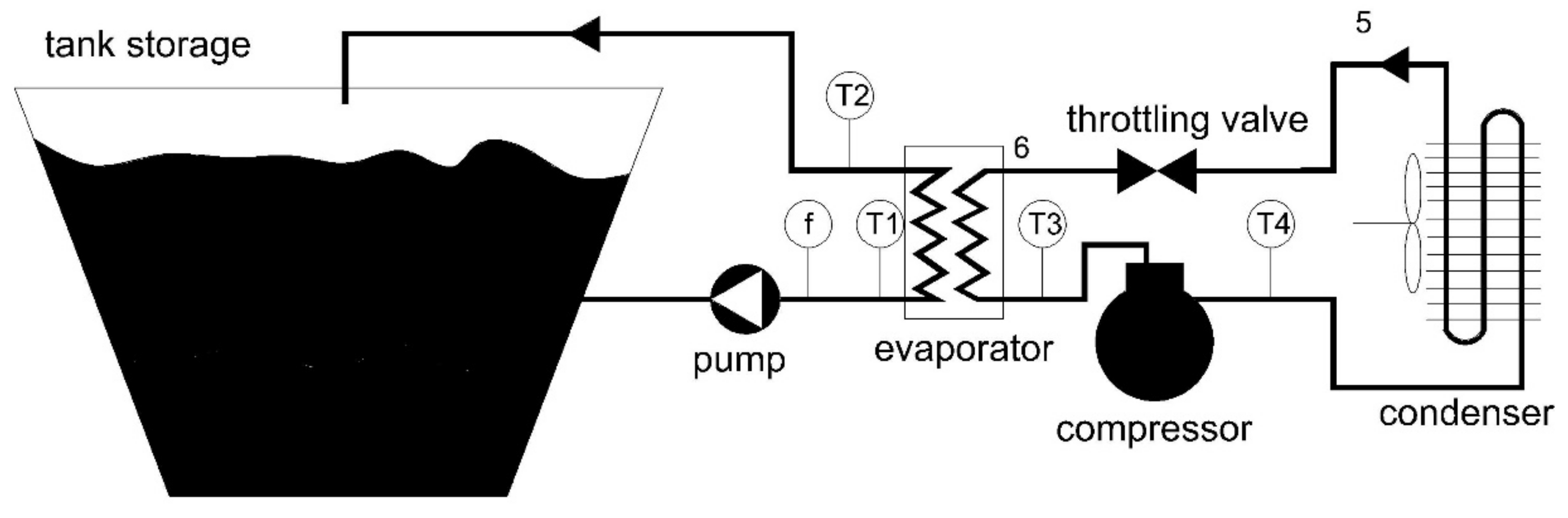
2.1. Experimental Apparatus

An ice generation system with a direct evaporating heat exchanger is not easy to fabricate while ensuring no ice blocking in the evaporator. So, few reports have been published regarding an ice generation system using supercooled water with a direct evaporating heat exchanger.
The experimental apparatus is shown in Figure 1. The system consisted of two circulations. The refrigeration circulation was composed of an evaporator, a compressor, and a throttle valve. The water circulation was composed of a pump, a crystal promoter, and the tank storage. A 3HP Copeland scroll compressor (ZB21KQ-PFJ-558) was used in the refrigeration circulation. The frequency of the compressor was invariable. A plate heat exchanger was used as the evaporator, so the whole system was compact. The plate heat exchanger was fabricated by the braze-welding method. The designed heat exchange was about 6 kW. For the condenser, the fan speed was controlled by a frequency converter. The pressure at the evaporator and condenser was measured with pressure gauges. The evaporator temperature T3 and temperature T4 could be read though pressure gauges as well. In the water circulation, the flow of water was controlled by the frequency converter. The inlet and outlet water temperatures of the evaporator were measured with Pt 100 thermal resistance. The accuracy was 0.1 K. The water flow was measured with an electromagnetic flowmeter. The accuracy was 0.045 m3/h. A multifunctional electrical meter was set up to measure the electrical power consumption of the entire system. We used ultrasonic waves to generate crystal after the supercooled water flowed out of the evaporator.
In the experimental process, refrigerant circulation was used to supply cooling for the water. The water temperature in the tank storage decreased gradually. The temperature T2 also decreased gradually in the ice generation process. When T2 was lower than 273.1 K, the outlet water from evaporator was supercooled. Then, the supercooled water was promoted by ultrasonic waves, and it generated crystals [22].

2.2. Calculation Methods

To calculate the performance of the entire system, a calculation method was built based on the energy conservation law. Two calculation methods were used to analyze the system performance.
For the first calculation method, the power of the compressor was invariable. The COP of the system could be calculated with the following equation:
COP s y s , 1 = Q ev W c o m + W p u m p + W f a n
where COPsys,1 is the COP of the entire system with the first calculation method; Qev is the heat transfer rate in the evaporator; Wcom, Wpump, and Wfan are the power of the compressor, pump, and fan, respectively. The power of the pump and fan could be measured with the multifunctional electrical meter. Qev could be calculated with the inlet temperature T1 and outlet temperature T2:
Q ev = c w m w ( T 1 T 2 )
where cw is the specific heat capacity of water, and mw′ is the water flow.
For the second calculation method, the output power of compressor was based on the theoretical refrigerant cycle that could be realized with variable frequency compressor.
The state points 3, 4, 5, and 6 are illustrated in Figure 1. The evaporator temperature and condenser temperature were obtained from measured data. The other state parameters were calculated based on the details of the cycle process. From state 3 to 4, the refrigerant underwent isentropic compression:
η c , s = h 4 s h 3 h 4 h 3
where h4s is the actual enthalpy in state point 4, and ηc,s is the adiabatic compressibility of the compressor. It was supposed that the adiabatic compressibility of the compressor was invariable during the ice slurry generation process. From state 4 to 5, the refrigerant underwent an isobaric process.
P 4 = P 5
Here, P4 and P5 are the pressure at state point 4 and 5. From state 5 to state 6, the refrigerant undergoes isenthalpic throttling process:
h 5 = h 6
where h4 and h5 are the enthalpy at state points 4 and 5, respectively. From state 6 to state 3, the refrigerant underwent an isobaric process:
P 6 = P 3
where P6 and P3 are the pressure at state points 6 and 3, respectively. In the evaporator, the heat exchange per unit of refrigerant was calculated with the enthalpy variation from state point 6 to state point 3:
Q c o o l = h 3 h 6
The isentropic compression work per unit of refrigerant [23] was defined as:
W c o m = P 3 ν 3 n n 1 [ ( P 4 P 3 ) n 1 n 1 ]
where n is a polytropic exponent, and ν3 is the specific volume at state point 3. The power of compressor can be determined as:
W   c o m , 2 = Q ev / ( Q c o o l / W c o m )
The system COP was defined as the acquired cooling divided by the total consumed electrical energy:
COP s y s , 2 = Q ev W c o m , 2 / η m e c h / η m o t o r / η c , s + W p u m p + W f a n
where ηmech and ηmotor are the efficiency of the mechanical drive and the motor efficiency of the compressor, respectively. It was supposed that ηmech and ηmotor were invariable during the ice slurry generation process.
In the second calculation method, different state point parameters were acquired by reading the physical properties.

3. Results

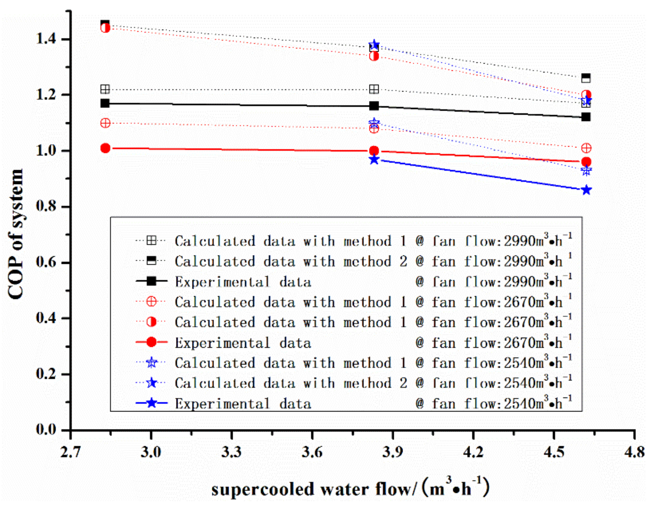
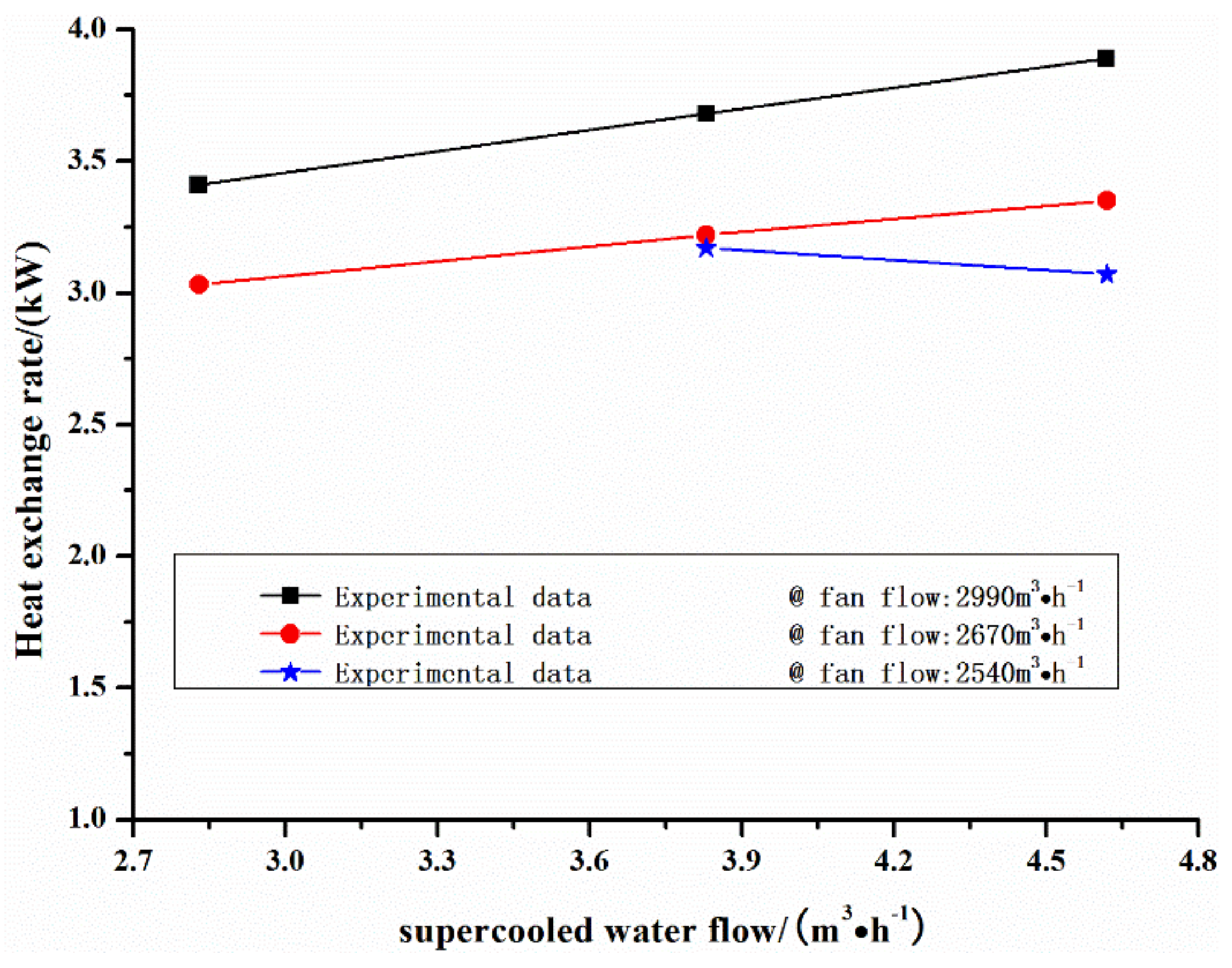
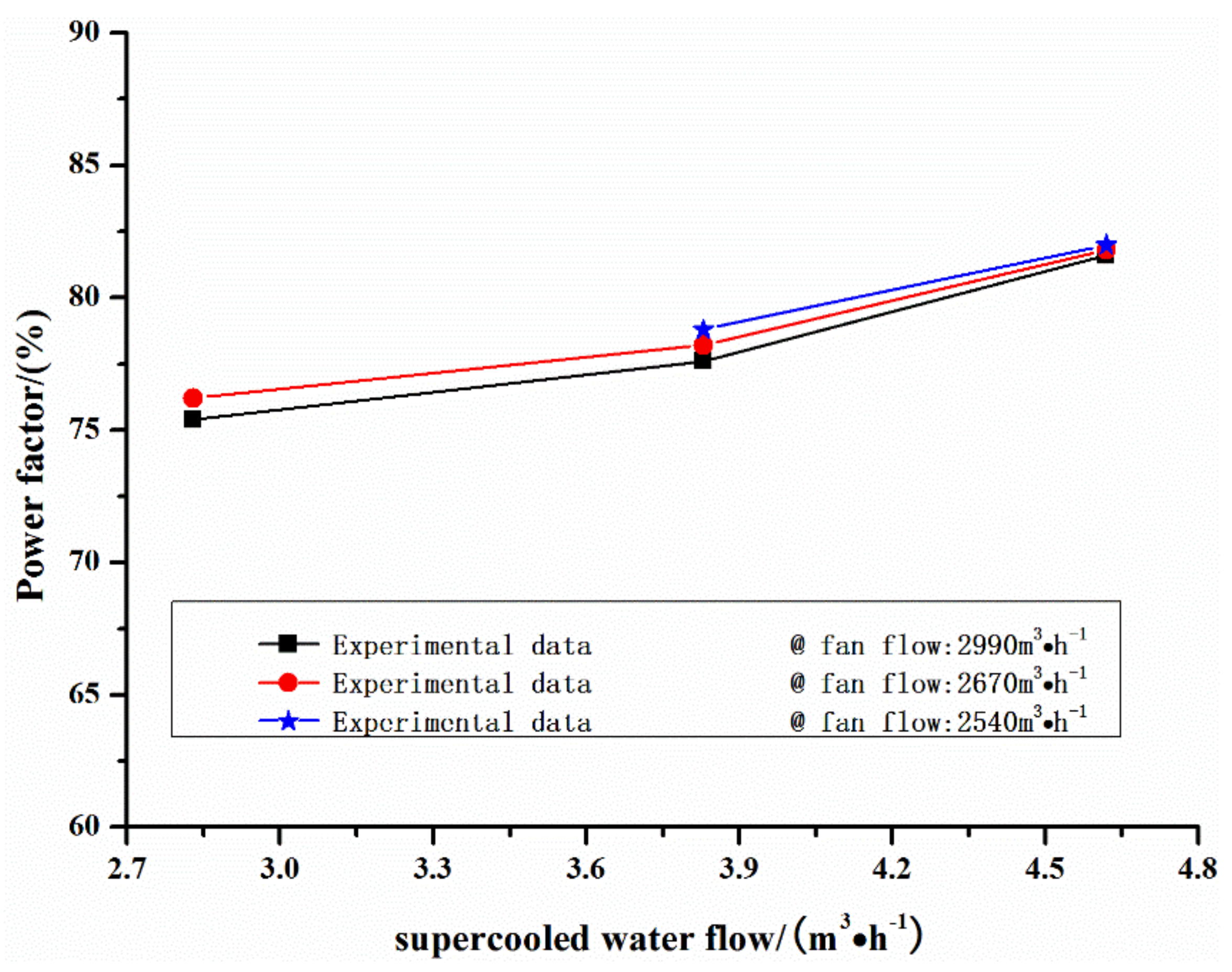
3.1. Experimental Result

The system with the directed evaporating method ran stably for a long time without the ice-blocking problem in proper parameter conditions until almost all the water turned into ice slurry in the tank storage. The tank storage and ice slurry are shown in Figure 2. It can be seen that the tank storage was full of ice slurry, but the system continued working. That meant that the system the with directed evaporating method could run stably without ice blocking. During the experimental process, water flow and fan flow were changed to examine the performance of the system. The experimental data and calculation data are shown in Figure 3. The COP of the entire system is defined by Equation (11):
COP s y s , 1 = Q ev W e l e c t r i c
where Welectric is the total electrical power of the system. The experimental data in Figure 3 were measured when the system could generate ice slurry stably for at least half an hour. In the different testing conditions shown in Figure 3, the evaporated temperature and temperature were slightly different. The evaporated temperature was about 269.6 K, while the condenser temperature was about 319 K. The ambient temperature was slightly high, and reached about 304 K. That was because the system was tested indoors during the summer. The system COP was about 1.2 when the condenser temperature was 318 K, as illustrated in Figure 3. The solid line represents the experimental results, while the dotted line represents the calculation results. The system COP could reach about 1.6 when the condenser temperature was 313 K, according the extra experimental result. For the 3HP Copeland scroll compressor, it could generate about 5 kW cooling when the evaporator temperature and temperature were 268.3 K and 323 K, respectively, according to the compressor’s technical manual. Since the pump power and fan power were respectively 0.87 kW and 0.2 kW, the estimated value of system COP was about 1.57. That meant that the experimental data were reasonable. According the publication, the COP of one system with the scraping method was about 1.13 in the actual running [24]; the condenser temperature of that system was 318.1 K, and the total input power was about 121 kW. There was no doubt that the system COP increased with the increase of refrigerating capacity. This suggested that the COP of the ice generation system using supercooled water with a directed evaporating method was higher than that of the system with a scraping method.
In the experimental data illustrated in Figure 3, the system COP decreased slightly when the supercooled water flow increased. The reason was that the pump power decreased when the water flow decreased. The pump power and fan power occupied an important proportion of the total power—about 18% in the system. However, the system COP apparently did not increase. That was because the heat exchange rate in the evaporator decreased when the water flow decreased. As illustrated in Figure 4, the heat exchange rate in the evaporator was 3.9 kW when the water flow and fan flow were 4.64 m3/h and 2990 m3/h, while the heat exchange rate in the evaporator was 3.6 kW when the water flow and fan flow were 3.84 m3/h and 2990 m3/h, respectively. That implied that refrigerant flow decreased because the evaporator temperature was almost unchanged. For an invariable frequency compressor, insufficient refrigerant flow leads to the increase of frictional loss power per unit refrigerant. When the water flow decreases, the pump power per unit water decreases but the frictional loss power per unit refrigerant increases. Then, that leads to slight increases in the system COP.
The fan flow had an influence on the system. The system COP decreased when the fan flow decreased. That was because the thermal dissipation capacity of the condenser was not enough when the fan flow was small. The heat exchange rate in the evaporator almost decreased when the fan flow decreased, as illustrated in Figure 4. That meant that refrigerant flow decreased because the evaporator temperature was almost unchanged. As aforementioned, frictional loss power per unit refrigerant increased in the invariable frequency compressor. It seemed that the frictional loss power increment per unit refrigerant was larger than the fan power decrement per unit refrigerant when the fan power increased. As a result, the system COP decreased when the fan flow decreased.
As aforementioned, the heat exchange rate in the evaporator increased with the increases in water flow and fan flow. As shown by the blue line in Figure 4, the heat exchange rate in the 3.78 m3/h water flow case was slightly higher than that in the 4.64 m3/h water flow case. That may have been due to the accuracy of the thermal resistance. When the water flow was large, 0.1 K could lead to a relatively large error. In the 4.64 m3/h water flow case, the heat exchange rate increased from 3.07 kW to 3.29 when the temperature difference increased by 0.05 K. Overall, the heat exchange rate in the evaporator increased with the increases in water flow and fan flow.
The power factor of the system is shown in Figure 5. It was calculated with Equation (12):
P F = P a c t P a p p
where Pact is the active power of the whole system, and Papp is the apparent power. They were measured with the multifunctional electrical meter. The power factor apparently increased with water flow. The power factor increased from 75.4% to 81.6% when the water flow increased from 2.85 m3/h to 4.64 m3/h. The reason may be that the power factor decreased with the load rate of the pump. In addition, pump power occupied an important proportion of the total power. The power factor was almost invariable when the fan flow increased, as shown in Figure 5. The reason may be that the fan power occupied only a small proportion of the total power. As in some countries, electrical fees are based on apparent energy. It is important to improve the power factor of the system.

3.2. System Stability

From the experimental measurement, the system could run steadily without ice blocking taking place. The supercooled water showed crystallization in the crystal promoter when the temperature was lower than 272.7 K. Ultrasonic waves helped to promote the crystallization of the supercooled water. When the ultrasonic wave was not turned on, ice blocking occurred in the evaporator, and the entire system could not run. The supercooling degree of the supercooled water could also be reduced by disturbing. When the ice slurry filled the tank storage, the ultrasonic waves could be turned on or off. This has no influence on the system stability at that time. Both water flow and fan flow had no influence on the transition temperature in the crystal promoter.
The supercooling temperature rank during the steady running process was from 272.5 K to 271.7 K. The velocity of the water flow had a great influence on the system’s stability. The diameter of the pipe was about 20 mm. When the velocity was lower than 2.1 m/s, ice blocking occurred at the exit of crystal promoter after half an hour of ice generation.

3.3. Calculation Results

Two calculation methods were used to obtain the performance of the entire system. The power of the compressor was invariable in the first calculation method, while the power of compressor was based on the theoretical refrigerant cycle in the second calculation method.
The calculation result based on the same experimental conditions is illustrated in Figure 3. It can be seen that the first calculation method agreed well with the experimental data. The error in the first calculation method was probably due to the actual running compressor power being slightly bigger than the rated power. It can be seen that there was a large deviation between the second calculation method and the experimental data. The comparison implied that the first calculation method simulated the invariable frequency compressor well. The second calculation method acquired the performance of the system equipped with the variable frequency compressor. The system COP with the second calculation method was larger than that with the first calculation method. That meant that the system COP could be improved by about 20% if the compressor power was based on theoretical refrigerant cycle. In the second calculation method, the system COP decreased with the increase in water flow. That was because the pump power per unit water increased with the increase of water flow based on the measured data. There was no doubt, because the friction factor of flow water was proportionate to the velocity squared when the channel structure was unchanged. In addition, in the second calculation method, the compressor power was based on theoretical refrigerant cycle. As a result, the system COP decreased with the increase in water flow. However, the water flow should not be too small. The system encountered ice blocking after about half an hour of ice generation when the water flow was below 2.4 m3/h. The system became unsteady when the water flow was too small.

4. Discussions

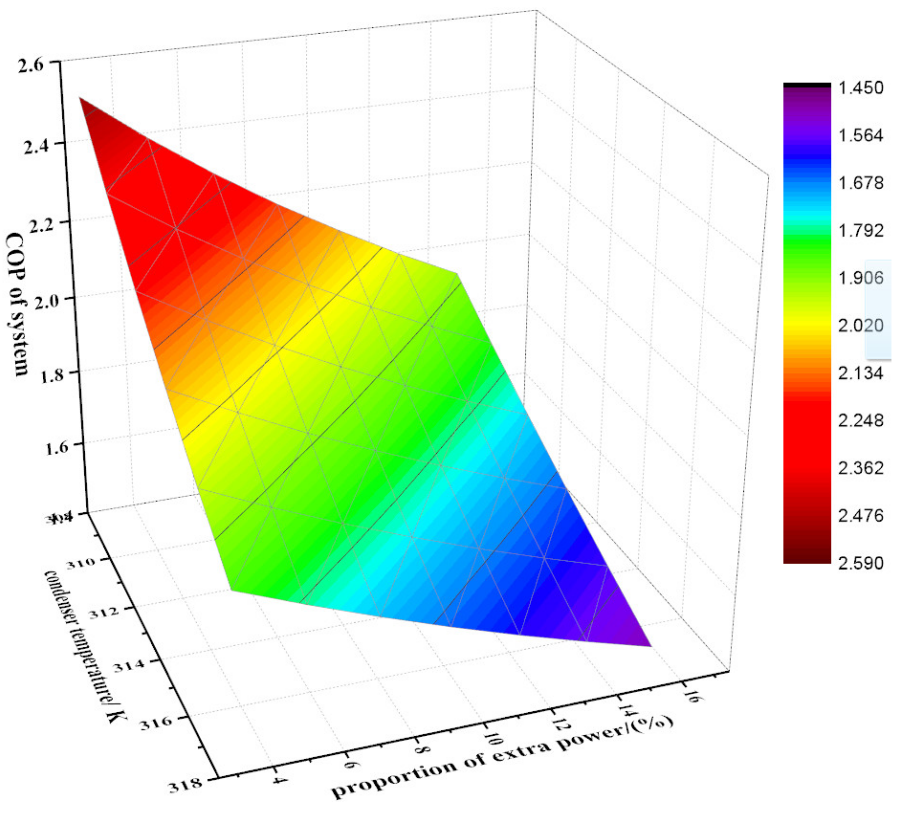
4.1. Influence of Condenser Temperature and Proportion of Extra Power

The condenser temperature and power proportion of the extra pump can play a great role in the system COP. Here, the extra power was the sum of the pump power and fan power. The proportion was equal to the cooling capacity divided by the sum of the pump power and fan power.
With the help of the second calculation method, the change in the system COP with condenser temperature and proportion of extra power is shown in Figure 6. The proportion was about 15% in our ice generation system using supercooled water, but the proportion could decrease to about 3% when the system cooling capacity increased to a large scale, such as 1000 kW [25]. It can be seen that the system COP was as large as 2.5 when the proportion of extra power was 3% and the condenser temperature was 308 K. That meant that the system could generate 1 ton of ice with about 35 kW•h of electricity. The system COP increased by about 2% when the extra power proportion decreased by about 1%. In a large-scale system, the condenser is usually cooled with liquid water, the temperature of which is about 303 K. The temperature difference of the heat exchanger (condenser) is about 3 K. That means the COP of a large-scale system can reach more than 2.5.

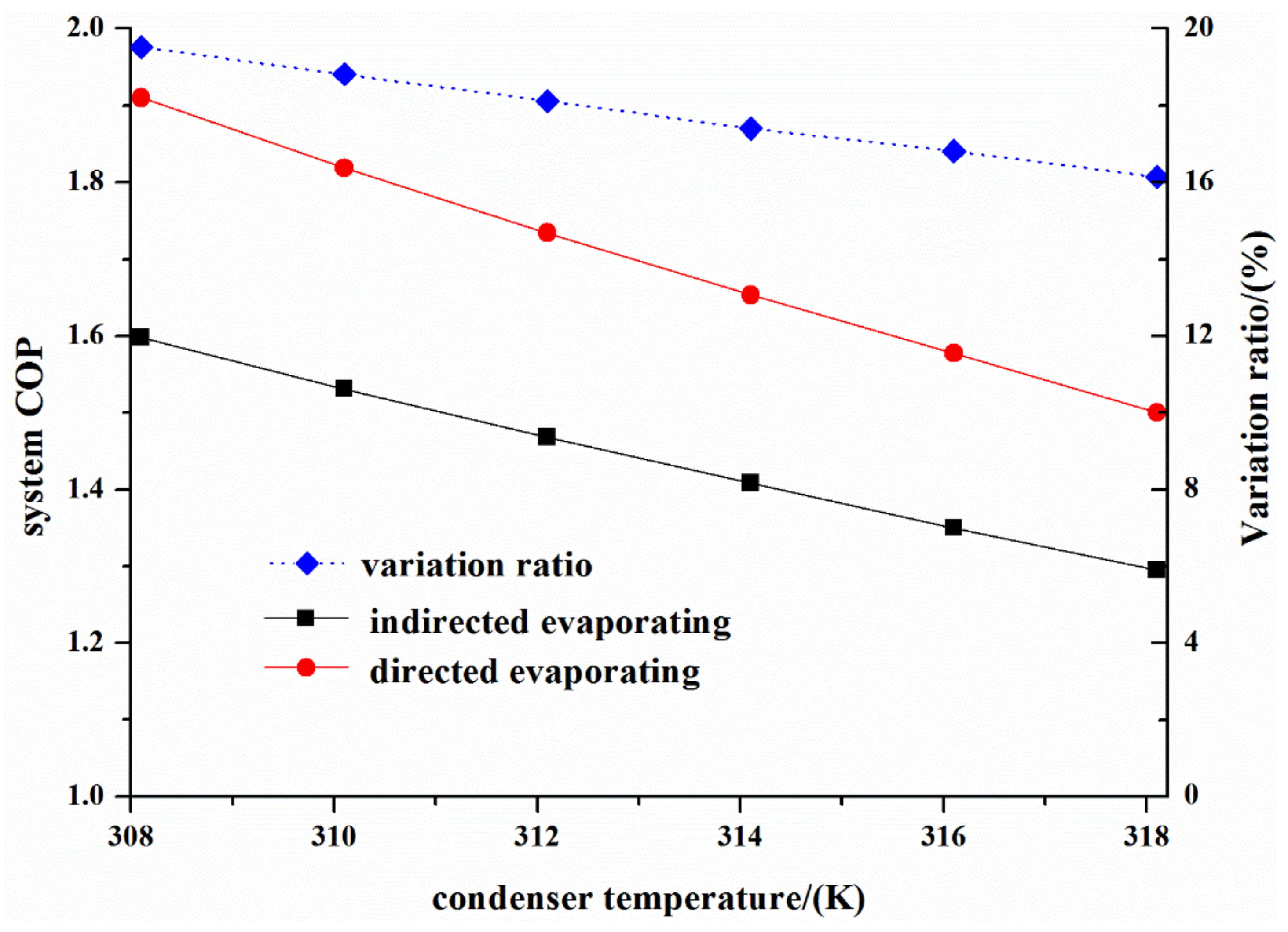
4.2. Comparison of the System Performance between Directed Evaporating and Indirected Evaporating

A secondary refrigerant cycle (indirected evaporating) is usually used in order to control the wall temperature and to ensure the steady heat transfer in the heat exchanger. In the ice generation system using supercooled water, the directed evaporating method, in which the secondary refrigerant cycle was canceled, has difficulty controlling the heat exchange temperature uniformity, and is seldom reported. The system performance with a directed evaporating method was analyzed in the previous section. A comparison of the two systems is discussed in this section.
The system COPs using the directed evaporating and indirected evaporating methods are shown in Figure 7. The data were acquired with the second calculation method. What is more, it supposed that an extra 0.25 kW of pump power was needed to run the secondary refrigerant cycle. Moreover, the evaporated temperature was 2 K lower than that of the directed evaporating method due to the secondary refrigerant cycle. The system COPs with the directed evaporating method and the indirected evaporating method decreased with the increase in condenser temperature. In addition, the system COP with directed evaporating method was about 16% higher than that with the indirected evaporating method, as illustrated in Figure 7. The increment ratio slightly decreased with the increase in condenser temperature. The increment ratio decreased from 19.5% to 16.1% when the condenser temperature increased from 308 K to 318 K. For the directed evaporating method, the system COP increased by about 2.4% when the condenser temperature increased by 1 K. For the indirected evaporating method, the system COP increased by about 2.2% when the condenser temperature increased by 1 K. Placing the system at a low ambient temperature was important to improving the system COP.

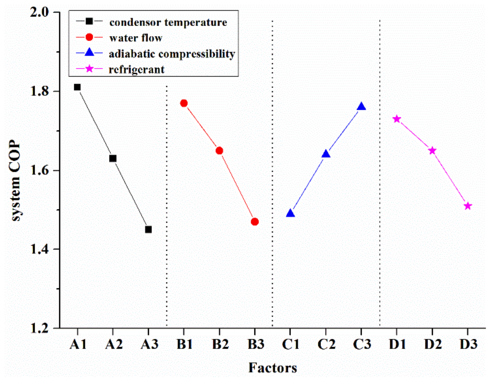
4.3. The Influence Factors of System

An orthogonal test based on calculation was built to quantify the influence of different critical parameters. The second calculation method was used in the simulation. The designed parameters, including condenser temperature, water flow, adiabatic compressibility of the compressor, and refrigerant were considered. In ice slurry generation using supercooled water, the evaporator temperature is usually invariable. Therefore, it was set to 270.1 K. The orthogonal array matrix L9 (34) with four factors and three levels is shown in Table 1. Four critical factors were marked: factor A (condenser temperature), factor B (water flow), factor C (adiabatic compressibility), and factor D (refrigerant). The factors and levels design were based on special rules, and they were uniformly distributed. What is more, the number of levels occurring in any two columns was equal.
Nine trials were run based on the matrix in Table 1 in order to quantify the influence of different factors. Each row in the matrix represented one case with different factors and levels. As can be seen in Table 1, the three levels of factor A occurred in case 1~case 3, case 4~case 6, and case 7~case 9, respectively. Kn was applied to evaluate the influence of different levels. In addition, the evaluation index R was applied to evaluate the influence of different factors:
k 1 = ( N 1 + N 2 + N 3 ) / 3 k 2 = ( N 4 + N 5 + N 6 ) / 3 k 3 = ( N 7 + N 8 + N 9 ) / 3
R = max ( k 1 , k 2 , k 3 ) min ( k 1 , k 2 , k 3 )
The larger the value of index R, the greater the influence of the specific factor on the system’s performance. The calculation results are shown in Table 2 and Figure 8. The system COP decreased when factors A, B, and D increased, or when factor C decreased. That meant that the system’s performance could be improved by decreasing the condenser temperature and water flow, or by increasing the adiabatic compressibility. For factor D, it was shown that refrigerant R22 was better than refrigerant R134a, while refrigerant R134a was better than refrigerant R143a. According to the calculation, the optimization case was A1B1C3D1. In case A1B1C3D1, the system COP was as large as 2.08. By comparison of index R, it was shown that the influence of factors on the system COP was ordered as follows: factor A > factor B > factor C > factor D. That meant that the condenser temperature played the most important role of the four factors. The system COP could be improved based on the rank of index R.

5. Conclusions

An ice generation system using supercooled water with a directed evaporating method was fabricated and tested. The system COP was measured. Then, two calculation methods were built to study the performance of entire ice slurry generation system. Moreover, the system performance was analyzed based on the experimental data and calculation methods.
The experimental result showed that the system could run steady without ice blocking in proper conditions where the supercooled water temperature was higher than 271.7 K and the velocity was larger than 2.1 m/s. The entire system COP could reach 1.6 when the condenser temperature was about 319 K. It was superior to the system that used a scraping method, according the public data. The supercooled water underwent crystallization in the crystal promoter when the temperature was lower than 272.7 K.
The system was analyzed based on the built calculation method. It was found that the system COP could be improved by about 20% if the compressor’s output power was based on the theoretical refrigerant cycle. The system COP could reach about 2.5 if the proportion of extra power was 3% and the condenser temperature was 308 K.
Through calculations, it was found that the system COP with the directed evaporating method was about 14% higher than that with the indirected evaporating method. The increment ratio slightly decreased with the increase of condenser temperature.
An orthogonal test based on calculation was built to quantify the influence of different critical parameters. The influence of factors on the system COP was ordered as follows: condenser temperature > water flow > adiabatic compressibility > refrigerant.
This work can provide a good look at the performance of an ice generation system using supercooled water with a directed evaporating method. It can play an important role in guiding the design of an ice slurry generation system that uses supercooled water.

Author Contributions

Conceptualization, M.C. and W.S.; methodology, M.C.; software, M.C.; validation, D.F.; formal analysis, M.C. and D.F.; investigation, D.F.; resources, Z.F.; data curation, D.F.; writing—original draft preparation, M.C.; writing—review and editing, M.C. and W.S.; visualization, M.C.; supervision, Z.F.; project administration, W.S.; funding acquisition, W.S. All authors have read and agreed to the published version of the manuscript.

Funding

The authors would like to thanks for supports by the Pilot project of the Chinese Academy of Sciences (XDA21070305), the National Key Research and Development Program of China (No. 2021YFE0112500), the European Union’s Horizon 2020 research and innovation programme under the Marie Skłodowska-Curie grant agreement (No 10100797).

Institutional Review Board Statement

Not applicable.

Informed Consent Statement

Not applicable.

Data Availability Statement

Not applicable.

Conflicts of Interest

The authors declare no conflict of interest. The funders had no role in the design of the study; in the collection, analyses, or interpretation of data; in the writing of the manuscript; or in the decision to publish the results.

Nomenclature

cwSpecific heat capacity of water (kJ/(K*kg))
COPsys,1Coefficient of performance of system with the first calculation method
hEnthalpy per unit of refrigerant (kJ/kg)
mwWater flow (kg/s)
nPolytropic exponent
PactActive power of the entire system (kW)
PappApparent power (kW)
QevHeat transfer rate in the evaporator (kW)
Q c o o l Heat exchange per unit of refrigerant (kJ/kg)
TTemperature (K)
WcomPower of compressor (kW)
WelectricTotal electrical power of the system(kW)
WpumpPower of pump (kW)
WfanPower of fan (kW)
W c o m Isentropic compression work per unit of refrigerant (kJ/kg)
ηc,sAdiabatic compressibility of the compressor
ηmechEfficiency of the mechanical drive
ηmotorMotor efficiency of the compressor
νSpecific volume (m3/kg)

References

  1. IRENA, IEA and REN21(2020), ‘Renewable Energy Policies in a Time of Transition: Heating and Cooling’. IRENA, OECD/IEA and REN21. Available online: https://irena.org/-/media/Files/IRENA/Agency/Publication/2020/Nov/IRENA_IEA_REN21_Policies_Heating_Cooling_2020.pdf (accessed on 1 August 2021).
  2. Tian, Q.; He, G.; Wang, H.; Cai, D. Simulation on transportation safety of ice slurry in ice cooling system of buildings. Energy Build. 2014, 72, 262–270. [Google Scholar] [CrossRef]
  3. Kauffeld, M.; Gund, S. Ice slurry—History, current technologies and future developments. Int. J. Refrig. 2019, 99, 264–271. [Google Scholar] [CrossRef]
  4. Wang, J.; Wang, S.; Zhang, T.; Liang, Y. Numerical investigation of ice slurry isothermal flow in various pipes. Int. J. Refrig. 2013, 36, 70–80. [Google Scholar] [CrossRef]
  5. Wang, J.; Battaglia, F.; Wang, S.; Zhang, T.; Ma, Z. Flow and heat transfer characteristics of ice slurry in typical components of cooling systems: A review. Int. J. Heat Mass Transf. 2019, 141, 922–939. [Google Scholar] [CrossRef]
  6. Kim, M.J.; Yu, J.S.; Lim, J.K.; Choe, S.Y. A Study on the Measuring Method of Ice Slurry Viscosity Using the Falling Sphere Viscometer. Korean J. Air-Cond. Refrig. Eng. 2007, 19, 593–598. [Google Scholar]
  7. Kitanovski, A.; Poredoš, A. Concentration distribution and viscosity of ice-slurry in heterogeneous flow. Int. J. Refrig. 2002, 25, 827–835. [Google Scholar] [CrossRef]
  8. Kamyar, A.; Aminossadati, S.M.; Leonardi, C.R. Thermo-Hydrodynamics of a Helical Coil Heat Exchanger Operated with a Phase-Change Ice Slurry as a Refrigerant. Heat Transf. Eng. 2019, 40, 283–294. [Google Scholar] [CrossRef]
  9. Mellari, S.; Boumaza, M.; Egolf, P. Physical modeling, numerical simulations and experimental investigations of Non-Newtonian ice slurry flows. Int. J. Refrig. 2012, 35, 1284–1291. [Google Scholar] [CrossRef]
  10. Xu, A.; Liu, Z.; Zhao, T.; Wang, X. Population balance model of ice crystals size distribution during ice slurry storage. Int. J. Air-Cond. Refrig. 2014, 22, 1440001. [Google Scholar] [CrossRef]
  11. Xu, D.; Liu, Z.; Cai, L.; Tang, Y.; Yu, Y.; Xu, A. A CFD-PBM approach for modeling ice slurry flow in horizontal pipes. Chem. Eng. Sci. 2018, 176, 546–559. [Google Scholar] [CrossRef]
  12. Liu, X.; Li, Y.; Zhuang, K.; Fu, R.; Lin, S.; Li, X. Performance Study and Efficiency Improvement of Ice Slurry Production by Scraped-Surface Method. Appl. Sci. 2018, 9, 74. [Google Scholar] [CrossRef] [Green Version]
  13. Jun, M.A.; Zhao, H.X.; Zhou, S.; Zhou, Y. Experimental study of ice slurry generation using vacuum method. J. Therm. Sci. Technol. 2015, 14, 255–258. [Google Scholar] [CrossRef]
  14. Wijeysundera, N.; Hawlader, M.; Andy, C.W.B.; Hossain, M. Ice-slurry production using direct contact heat transfer. Int. J. Refrig. 2004, 27, 511–519. [Google Scholar] [CrossRef]
  15. Chen, D.; Zhang, C.; Rong, H.; Wei, C.; Gou, S. Experimental study on seawater desalination through supercooled water dynamic ice making. Desalination 2020, 476, 114233. [Google Scholar] [CrossRef]
  16. Yan, J.-H.; Zhang, X.-S.; Chen, Y.; Zhou, B. An improved ice producing system of assisting liquid desiccant evaporative supercooled water. Energy Build. 2013, 62, 530–538. [Google Scholar] [CrossRef]
  17. Bédécarrats, J.-P.; David, T.; Castaing-Lasvignottes, J. Ice slurry production using supercooling phenomenon. Int. J. Refrig. 2010, 33, 196–204. [Google Scholar] [CrossRef]
  18. Janjua, Z.A.; Turnbull, B.; Choy, K.-L.; Pandis, C.; Liu, J.; Hou, X.; Choi, K.-S. Performance and durability tests of smart icephobic coatings to reduce ice adhesion. Appl. Surf. Sci. 2017, 407, 555–564. [Google Scholar] [CrossRef]
  19. Golovin, K.; Kobaku, S.P.R.; Lee, D.H.; DiLoreto, E.T.; Mabry, J.M.; Tuteja, A. Designing durable icephobic surfaces. Sci. Adv. 2016, 2, e1501496. [Google Scholar] [CrossRef] [Green Version]
  20. Wang, H.; Feng, R.; Duan, H.; Chen, A. Investigation into the ice generator with double supercooled heat exchangers. Appl. Therm. Eng. 2016, 98, 380–386. [Google Scholar] [CrossRef]
  21. Inaba, H.; Takeya, K.; Nozu, S. Fundamental Study on Continuous Ice Making Using Flowing Supercooled Water. JSME Int. J. Ser. B 1994, 37, 385–393. [Google Scholar] [CrossRef] [Green Version]
  22. Zhang, X.; Inada, T.; Yabe, A.; Lu, S.; Kozawa, Y. Active control of phase change from supercooled water to ice by ultrasonic vibration 2. Generation of ice slurries and effect of bubble nuclei. Int. J. Heat Mass Transf. 2001, 44, 4533–4539. [Google Scholar] [CrossRef]
  23. Li, W. Simplified steady-state modeling for hermetic compressors with focus on extrapolation. Int. J. Refrig. 2012, 35, 1722–1733. [Google Scholar] [CrossRef]
  24. Liu, Z.B.; Wu, R.H.; Yu, H. Operation test for heat pump heating system using latent heat of water transformation. Heat. J. Heat. Air Cond. 2019, 49, 96–100. [Google Scholar]
  25. Wang, S.Q.; Jiang, X.Y.; Lin, K.Y. Analysis of several hot points on dynamic ice storage technology with sub-cooled water. Refrig. Air-Cond. 2019, 19, 75–79. [Google Scholar] [CrossRef]
Figure 1. Schematic diagram of the experimental apparatus.
Energies 14 07021 g001
Figure 2. (a) Ice slurry system with supercooled water method. (b) Ice slurry generated with supercooled water method. The system was running at the conditions in which the water flow and the fan flow were 4.64 m3/h and 2990 m3/h.
Energies 14 07021 g002
Figure 3. System COP in different conditions. The solid line represents the experimental results, while the dotted line represents the calculation results.
Energies 14 07021 g003
Figure 4. Change in the heat exchange rate of evaporator vs. supercooled water flow.
Energies 14 07021 g004
Figure 5. The change in power factor of the entire system vs. supercooled water flow.
Energies 14 07021 g005
Figure 6. The change in system COP vs. condenser temperature and proportion of extra power.
Energies 14 07021 g006
Figure 7. Changes in system COPs and variation ratio vs. condenser temperature. The black solid line represents the calculation data in the indirected evaporating method, while the red solid line represents the calculation data in the directed evaporating method.
Energies 14 07021 g007
Figure 8. The changes in system COP vs. the mean value of different factors.
Energies 14 07021 g008
Table 1. The values of the system COP in the L9 (34) matrix.
Case NumberFactorResult
ABCDCOP
1352.850.65R221.91
2353.740.75R134a1.86
3354.640.85R143a1.67
4402.850.75R143a1.66
5403.740.85R221.88
6404.640.65R134a1.35
7452.850.85R134a1.74
8453.740.65R143a1.21
9454.640.75R221.40
Table 2. The mean values of different factors.
Case NumberFactor
ABCD
k11.811.771.491.73
k21.631.651.641.65
k31.451.471.761.51
R0.360.300.270.22
Publisher’s Note: MDPI stays neutral with regard to jurisdictional claims in published maps and institutional affiliations.

