
A Study on the Power Line Operation Strategy by the Energy Storage System to Ensure Hosting Capacity of Distribution Feeder with Electrical Vehicle Charging Infrastructure


Abstract
1. Introduction
1.1. Introduction
1.2. Contributions
- -
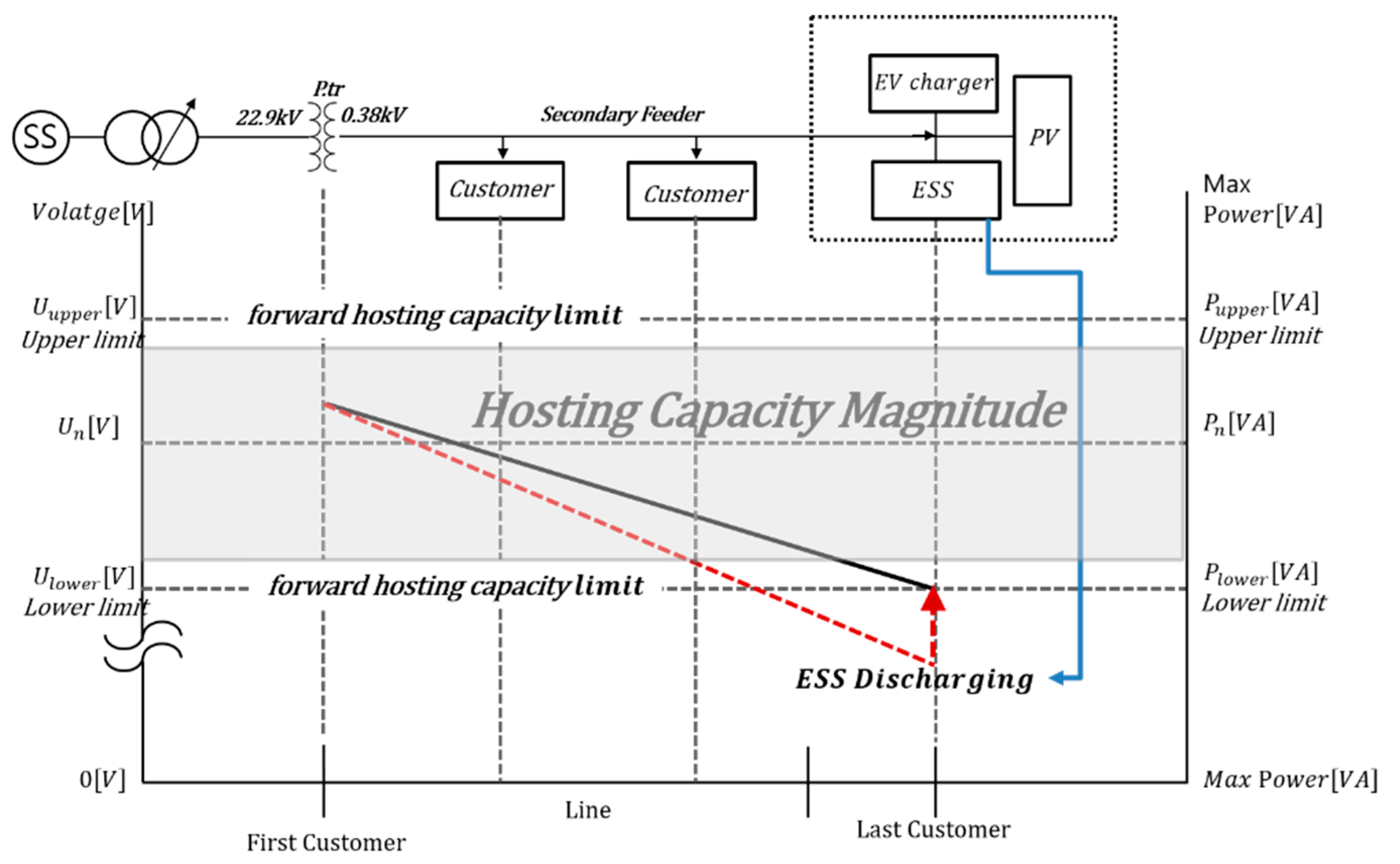
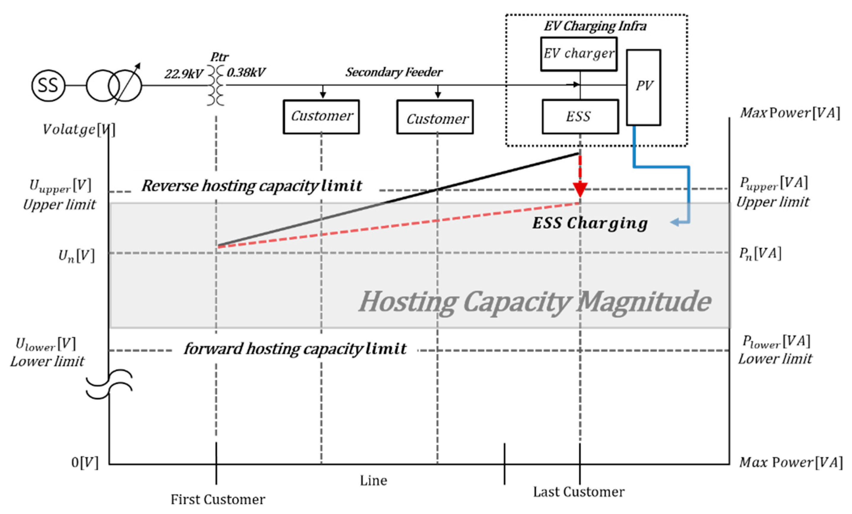
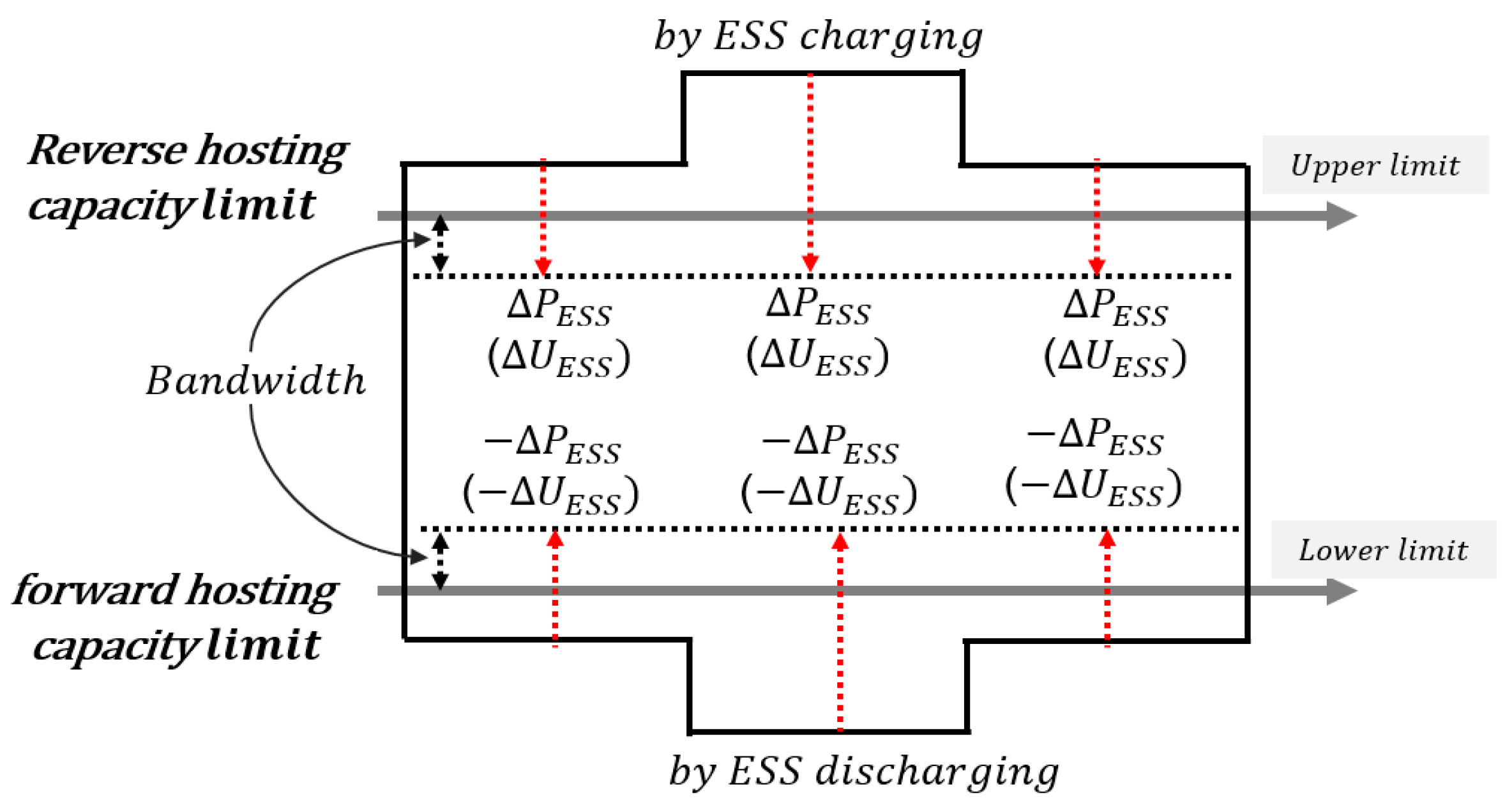
- This paper adopts control strategy of ESS for VPL operation to ensure hosting capacity in distribution feeder, which is interconnected with EVC infrastructure. To operate the VPL, power in the distribution feeder with EVC infrastructure is compensated by the ESS as much as the target hosting capacity () of section using the PCR and VCR, considering the bandwidth of ESS. Under these concepts, verification for the proposed operation strategy is performed by the actual test at distribution feeder interconnected with EVC infrastructure.
- -
- In this paper, two cases are analyzed based on ESS control strategy using the VPL method, which is the possible operation of the distribution feeder interconnected EVC infrastructure without reinforcing the power line. The first case is the characteristic test for hosting capacity at DUT (device under test) location of distribution feeder interconnected with EVC infrastructure when ESS for VPL operation is not introduced. The second case is the characteristic test for hosting capacity at DUT location of distribution feeder interconnected with EVC infrastructure when ESS for VPL operation is introduced.
2. Operation Characteristics of ESS for VPL to Stably Introduce of EVC Infrastructure
2.1. VPL Characteristic
2.2. Operation Characteristic of ESS to Stably Introduce of EVC Infrastructure
3. Operation Strategy of the ESS for VPL
3.1. Control Concept of ESS for VPL Operation
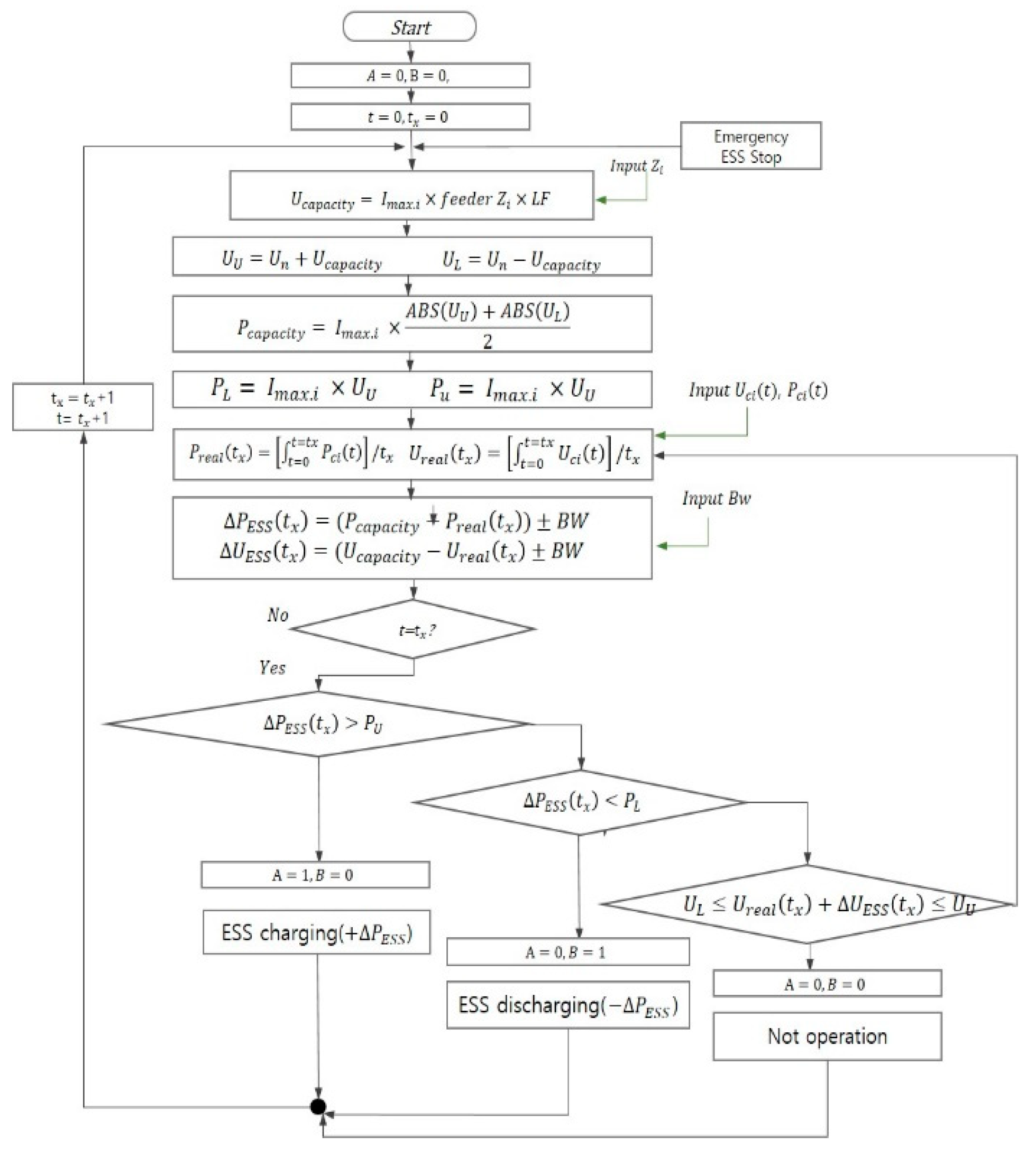
3.2. Control Strategy of ESS for VPL Operation
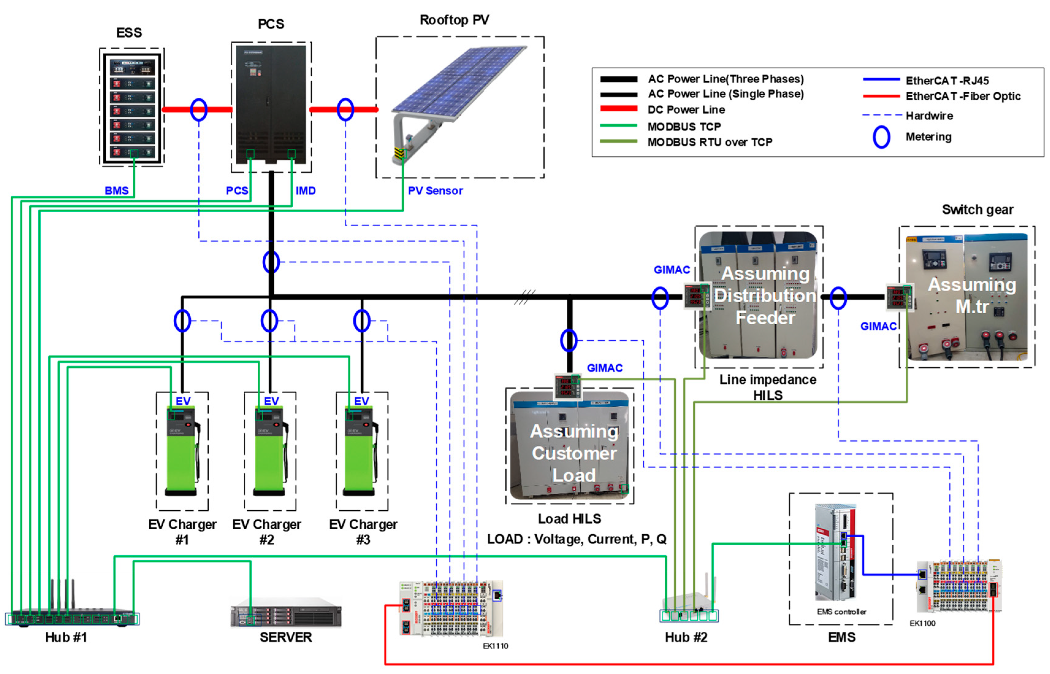
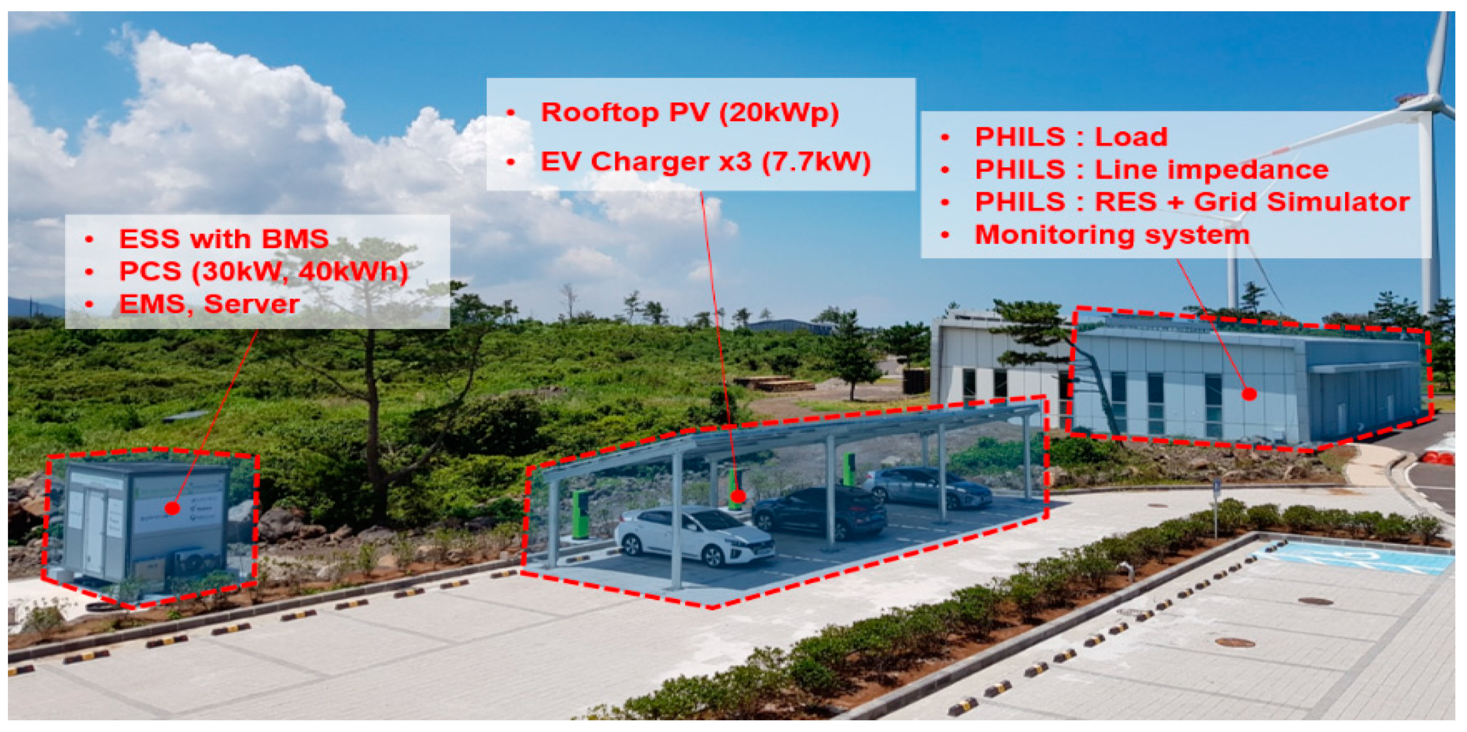
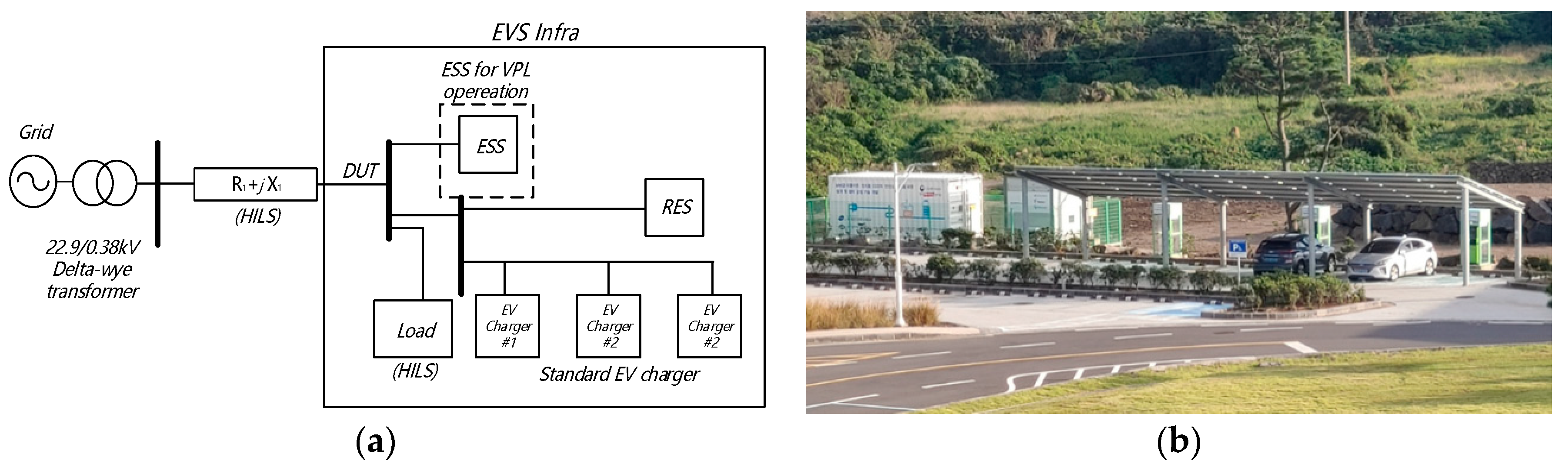
4. Implementation of EVS Infrastructure
5. Case Studies
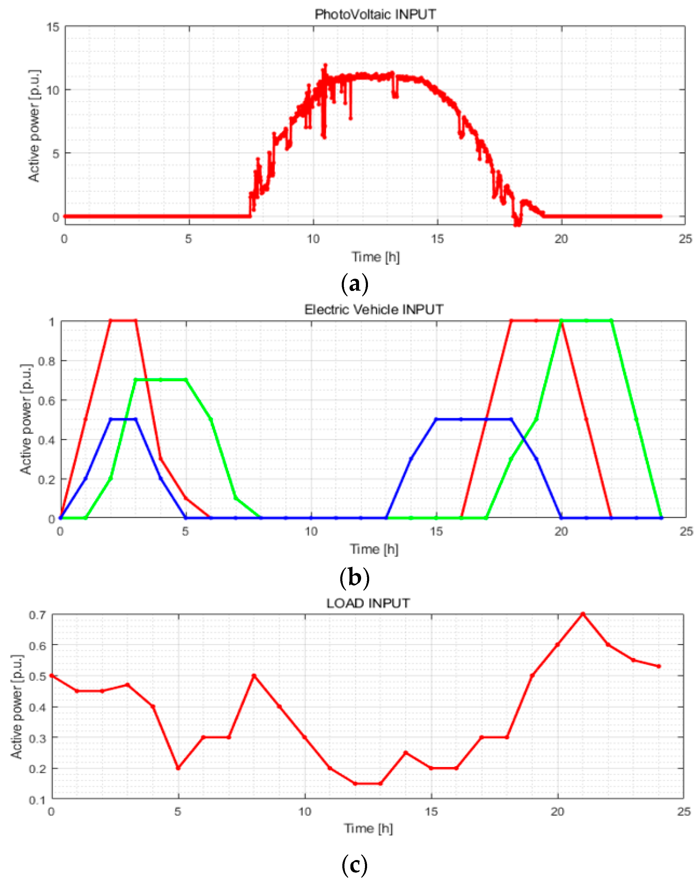
5.1. Test Condition
5.2. Results and Discussion
5.3. Hosting Capacity Characteristic by Proposed Strategy
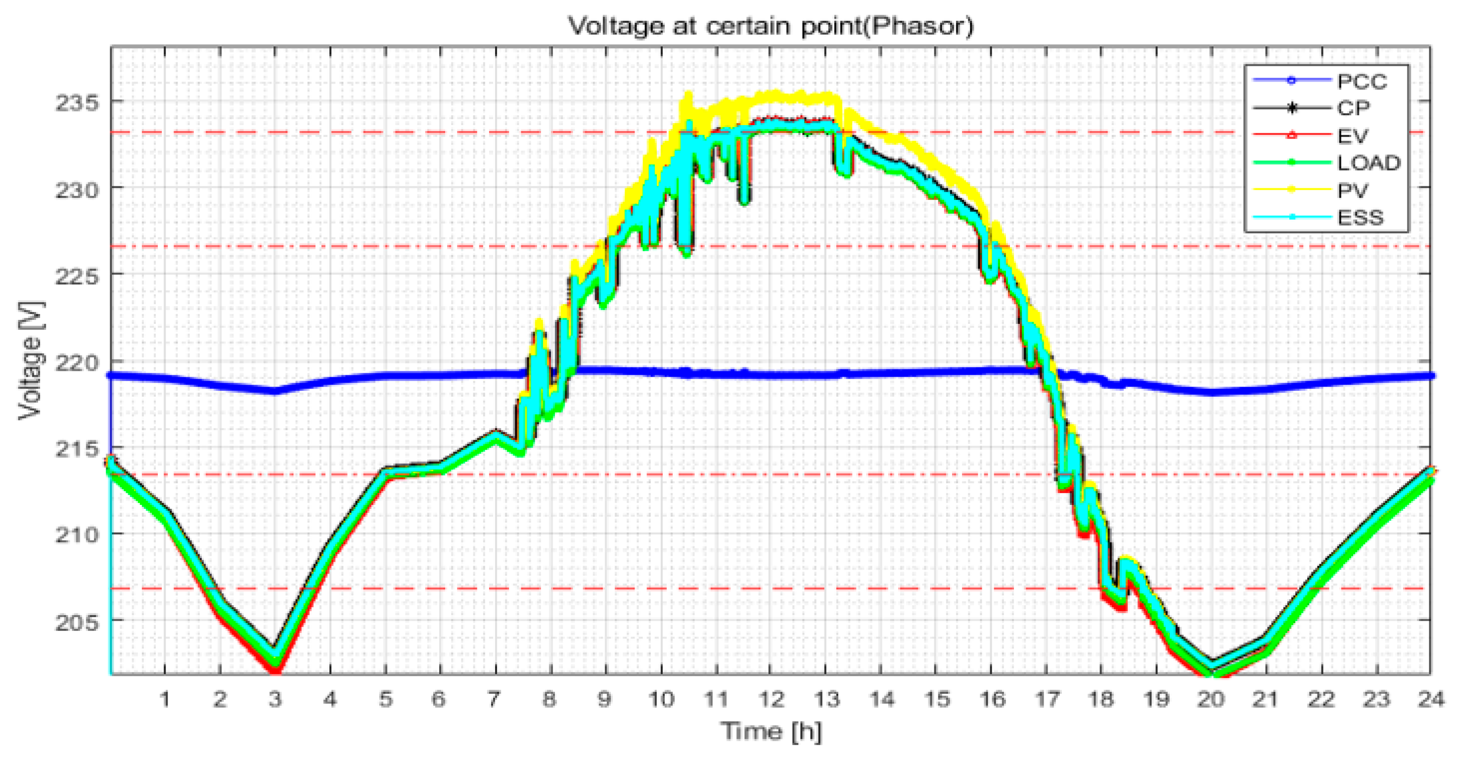
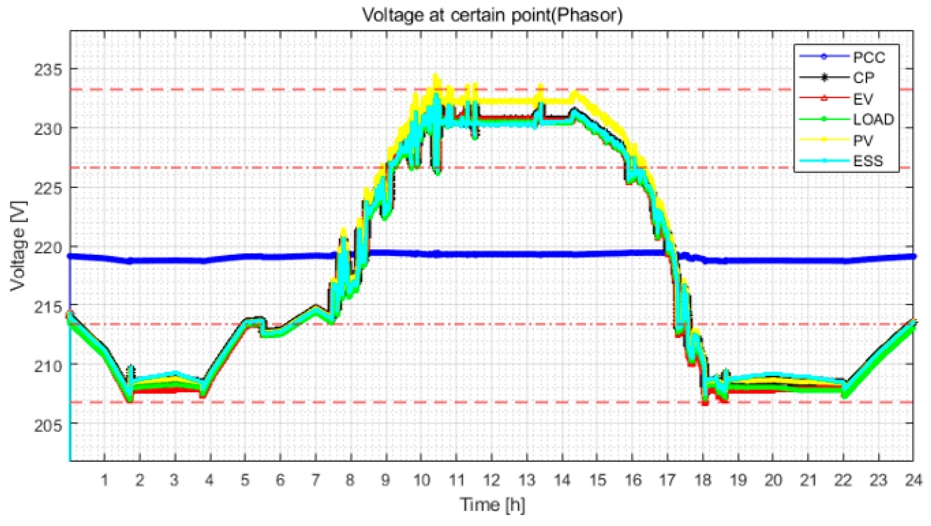
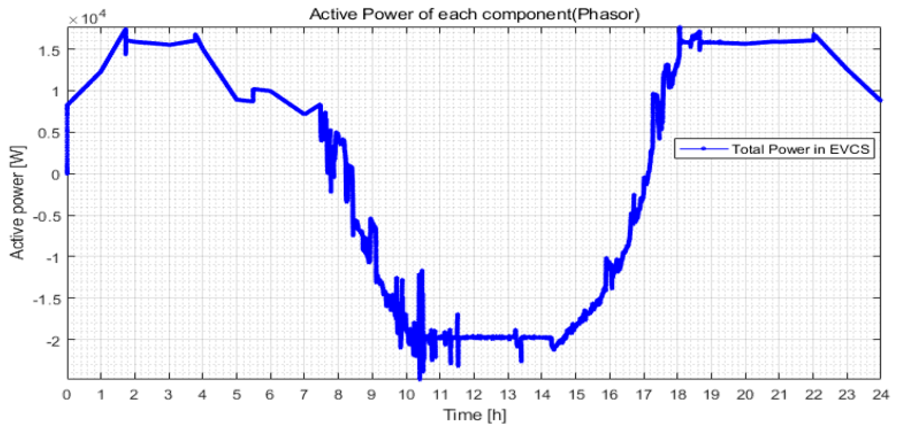
5.3.1. Analysis of Hosting Capacity Characteristic without ESS
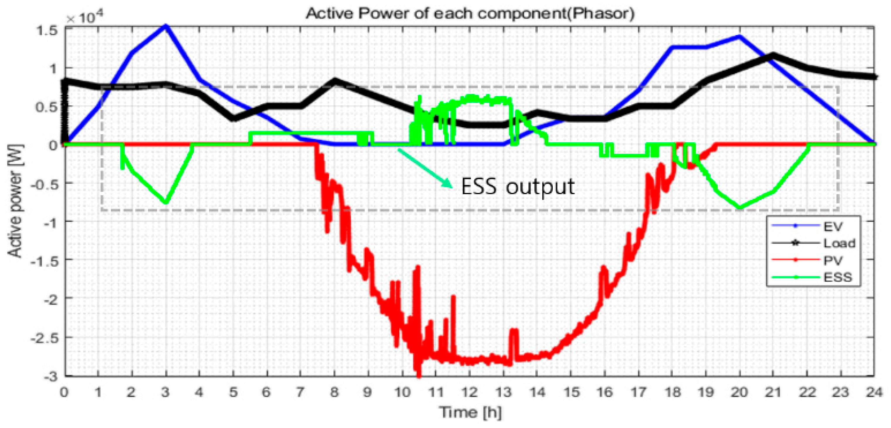
5.3.2. Analysis of the Hosting Capacity Characteristic by ESS Operation
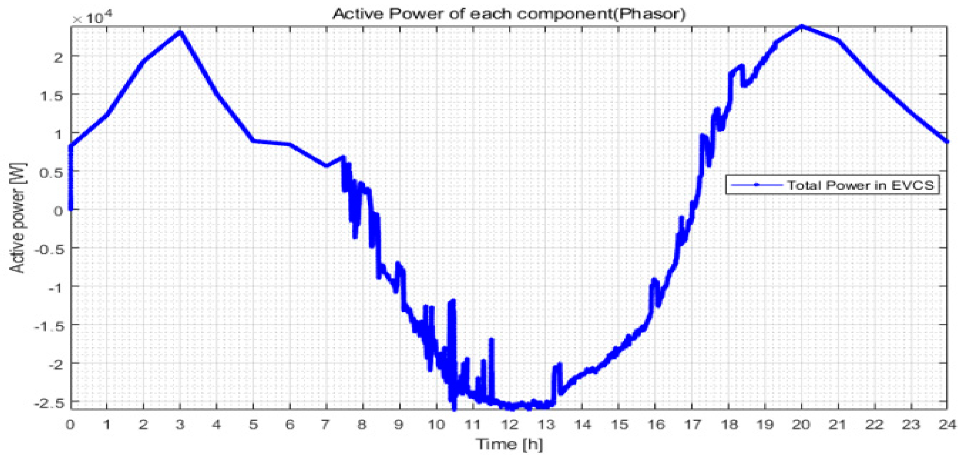
5.4. ESS Control Characteristic by Proposed Strategy
6. Conclusions
- (1)
- To keep within the existing hosting capacity of distribution feeder and allowable limit, this paper presents the ESS operation using the VPL method, which makes possible the operation of distribution feeder interconnected EVC infrastructure without reinforcing the power line, instead of reinforcing or building additional transmission and distribution systems.
- (2)
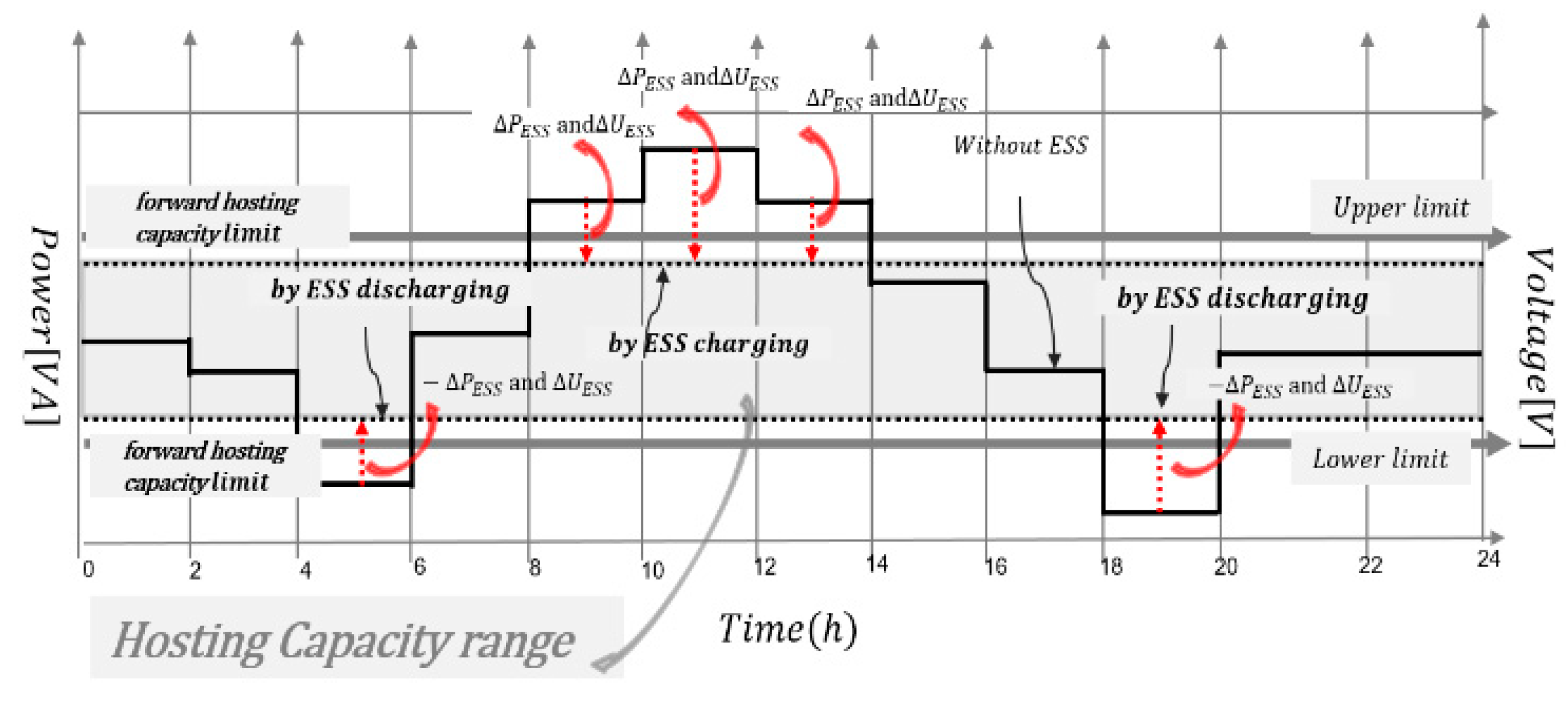
- In order to overcome the problem of violating the hosting capacity at the feeder with EVC infrastructure, an operation method for stabilization of the hosting capacity by the ESS control strategy was proposed. Based on the test result using the 30 kW scaled EVC infrastructure, power value at all-time can be perfectly kept within the hosting capacity by control strategy of ESS for VPL operation at the EVS infrastructure.
- (3)
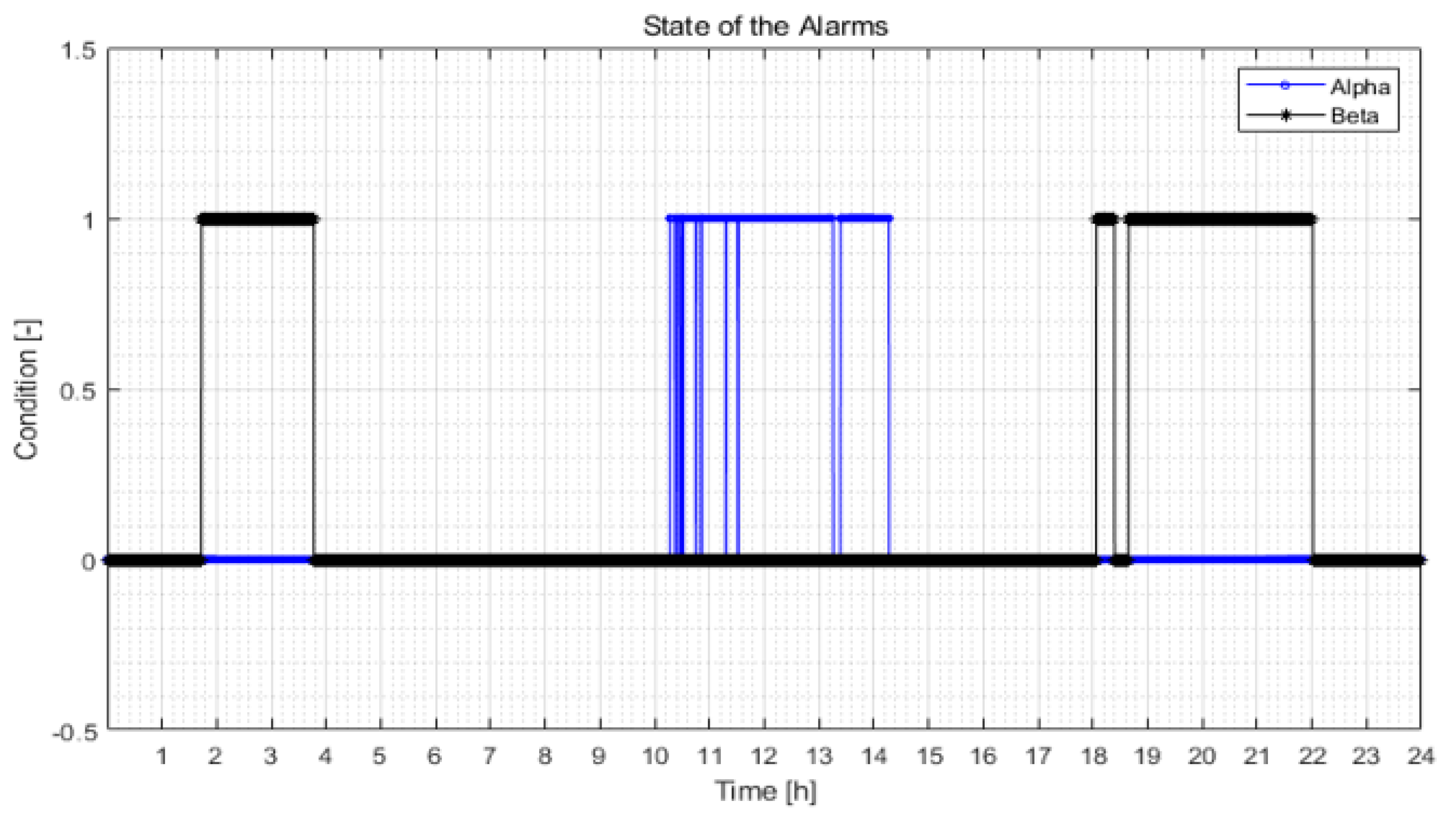
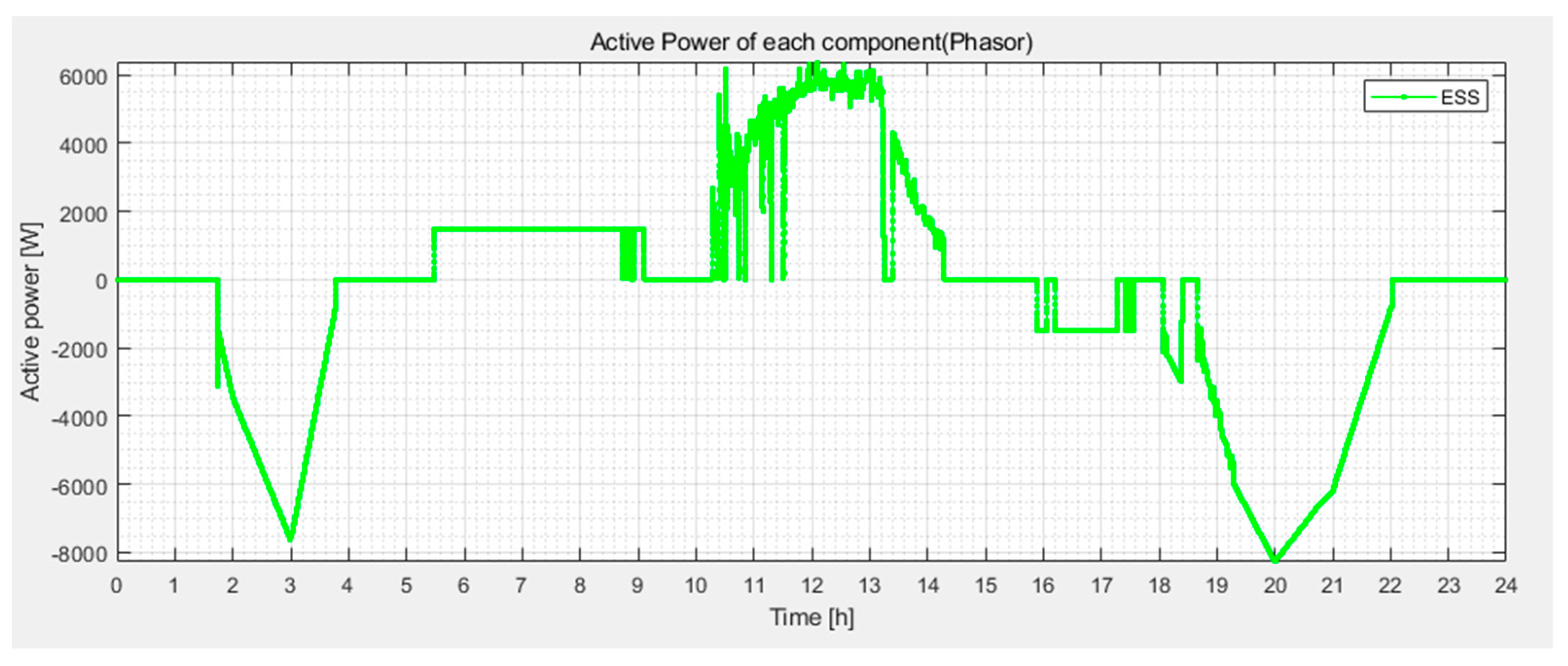
- From the verification result for the control characteristic, it is clear that ESS was accurately controlled by the operation determination signal. Moreover, when real-time power magnitude cannot be maintained within the hosting capacity, it is confirmed that the ESS properly compensates power within the hosting capacity by charging and discharging according to the reverse power flow and the forward power flow. Based on the control characteristics results of ESS, it is clear that the proposed control strategy of ESS for VPL operation is a useful tool. Further, it is clear that the introduction of ESS for VPL function can also expect an indirect benefit such as reduction of the investment cost by the effective utilization of distribution feeder facilities.
Author Contributions
Funding
Institutional Review Board Statement
Informed Consent Statement
Data Availability Statement
Conflicts of Interest
References
- Rho, D.-S.; Kook, K.-S.; Wang, Y.-P. Optimal Algorithms for Voltage Management in Distribution Systems Interconnected with New Dispersed Sources. J. Electric. Eng. Technol. 2011, 6, 192–201. [Google Scholar] [CrossRef]
- Kim, B.; Kim, G.; Lee, J.; Choi, S.; Rho, D. A Study on the Modeling of Step Voltage Regulator and Energy Storage System in Distribution System Using the PSCAD/EMTDC. J. Korea Acad. Ind. Coop. Soc. 2015, 16, 1355–1363. [Google Scholar]
- Kim, B.K.; Choi, S.S.; Wang, Y.P.; Kim, E.S.; Rho, D.S. A Study on the Control Method of Customer Voltage Variation in Distribution System with PV Systems. J. Electr. Eng. Technol. 2014, 10, 838–846. [Google Scholar] [CrossRef]
- Farag, H.E.; El-Saadany, E.F. Voltage Regulation in Distribution Feeders with High DG Penetration: From Traditional to Smart. In Proceedings of the 2011 IEEE Power and Energy Society General Meeting, Detroit, MI, USA, 24–28 July 2011; IEEE: Piscataway, NJ, USA, 2011; pp. 1–8. [Google Scholar]
- Kojovic, L.A. Modern techniques to study voltage regulator-DG interactions in distribution systems. In Proceedings of the 2008 IEEE/PES Transmission and Distribution Conference and Exposition, Chicago, IL, USA, 21–24 April 2008; IEEE: Piscataway, NJ, USA, 2008; pp. 1–6. [Google Scholar]
- Rubino, L.; Capasso, C.; Veneri, O. Review on plug-in electric vehicle charging architectures integrated with 538 distributed energy sources for sustainable mobility. Appl. Energy 2017, 207, 5392. [Google Scholar] [CrossRef]
- Madina, C.; Zamora, I.; Zabala, E. Methodology for assessing electric vehicle charging infrastructure business 540 models. Energy Policy 2016, 89, 284–293. [Google Scholar] [CrossRef]
- Sbordone, D.; Bertini, I.; Di Pietra, B.; Falvo, M.C.; Genovese, A.; Martirano, L. EV fast charging stations and energy 542 storage technologies: A real implementation in the smart micro grid paradigm. Electr. Power Syst. Res. 2015, 120, 96–108. [Google Scholar] [CrossRef]
- Serradilla, J.; Wardle, J.; Blythe, P.; Gibbon, J. An evidence-based approach for investment in rapid-charging 547 infrastructure. Energy Policy 2017, 106, 514–524. [Google Scholar] [CrossRef]
- Dong, X.; Mu, Y.; Xu, X.; Jia, H.; Wu, J.; Yu, X.; Qi, Y. A charging pricing strategy of electric vehicle fast 549 charging stations for the voltage control of electricity distribution networks. Appl. Energy 2018, 225, 857–868. [Google Scholar] [CrossRef]
- Leou, C.; Su, C.-L.; Lu, C.-N. Stochastic analyses of electric vehicle charging impacts on distribution 552 network. IEEE Trans. Power Syst. 2014, 29, 1055–1063. [Google Scholar] [CrossRef]
- Gray, M.K.; Morsi, W.G. Power quality assessment in distribution systems embedded with plug-in 554 hybrid and battery electric vehicles. IEEE Trans. Power Syst. 2015, 30, 663–671. [Google Scholar] [CrossRef]
- Virtual Power Lines Innovation Landscape Brief, IRENA 2020. 2020. Available online: www.irena.org (accessed on 1 September 2021).


| Concept | Number | Content for Function |
|---|---|---|
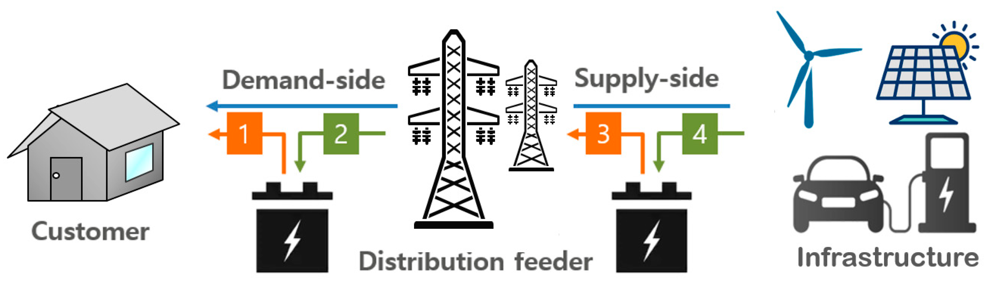
| Demand side |  | Discharges to address peak-to-peak load |
 | Charges when load is lower than RES and hosting capacity is available | |
| Supply side |  | Discharges to demand-side ESS when hosing capacity is available |
 | Charges using RES to avoid curtailment due to grid congestion |
| Classification | ||
|---|---|---|
| Charging operation (+) | 1 | 0 |
| Discharging operation (−) | 0 | 1 |
| Not in operation | 0 | 0 |
| EVC Infrastructure Configuration at Test Site | |||
|---|---|---|---|
| Grid | 3phase 380VL-L | Load capacity | Max. 30 kW Variable |
| PV Capacity | 20 kWp | Load pattern by load HILS | Residential Area |
| EV Charger | 7.7 kW | Line impedance per km | 0.2 + j0.4 step Variable |
| Wire type | Thr-cv 15 | feeder | 2 km 0.4 + j0.8 |
| ESS | 40 kWh (PCS 30 kW) | Transformer capacity | 50 kVA |
| Hosting Capacity Characteristic | ||||
|---|---|---|---|---|
| 70% | Hosting capacity | Existing | 30 kW | |
| VPL | 21 kW | |||
| Hosting Capacity Test Results | |||||
|---|---|---|---|---|---|
| 69.8% | Hosting capacity | Existing (Feeder) | condition | Max. 30.0 kW | |
| result | Max. 29.7 kW | ||||
| Additional available capacity | 7 kW (30.2%) | Pro posed (VPL) | condition | Max. 21.0 kW | |
| result | Max.20.8 kW | ||||
Publisher’s Note: MDPI stays neutral with regard to jurisdictional claims in published maps and institutional affiliations. |
© 2021 by the authors. Licensee MDPI, Basel, Switzerland. This article is an open access article distributed under the terms and conditions of the Creative Commons Attribution (CC BY) license (https://creativecommons.org/licenses/by/4.0/).
Share and Cite
Kim, B.; Park, J.-B.; Kim, D.-J. A Study on the Power Line Operation Strategy by the Energy Storage System to Ensure Hosting Capacity of Distribution Feeder with Electrical Vehicle Charging Infrastructure. Energies 2021, 14, 6976. https://doi.org/10.3390/en14216976
Kim B, Park J-B, Kim D-J. A Study on the Power Line Operation Strategy by the Energy Storage System to Ensure Hosting Capacity of Distribution Feeder with Electrical Vehicle Charging Infrastructure. Energies. 2021; 14(21):6976. https://doi.org/10.3390/en14216976
Chicago/Turabian StyleKim, Byungki, Jae-Bum Park, and Dae-Jin Kim. 2021. "A Study on the Power Line Operation Strategy by the Energy Storage System to Ensure Hosting Capacity of Distribution Feeder with Electrical Vehicle Charging Infrastructure" Energies 14, no. 21: 6976. https://doi.org/10.3390/en14216976
APA StyleKim, B., Park, J.-B., & Kim, D.-J. (2021). A Study on the Power Line Operation Strategy by the Energy Storage System to Ensure Hosting Capacity of Distribution Feeder with Electrical Vehicle Charging Infrastructure. Energies, 14(21), 6976. https://doi.org/10.3390/en14216976