Abstract
The increasing use of lithium batteries and the necessary integration of battery management systems (BMS) has led international standards to demand functional safety in electromobility applications, with a special focus on electric vehicles. This work covers the complete design of an enhanced automotive BMS with functional safety from the concept phase to verification activities. Firstly, a detailed analysis of the intrinsic hazards of lithium-based batteries is performed. Secondly, a hazard and risk assessment of an automotive lithium-based battery is carried out to address the specific risks deriving from the automotive application and the safety goals to be fulfilled to keep it under control. Safety goals lead to the technical safety requirements for the next hardware design and prototyping of a BMS Slave. Finally, the failure rate of the BMS Slave is assessed to verify the compliance of the developed enhanced BMS Slave with the functional safety Automotive Safety Integrity Level (ASIL) C. This paper contributes the design methodology of a BMS complying with ISO 26262 functional safety standard requirements for automotive lithium-based batteries.
1. Introduction
The electric vehicle market has increased over recent years doubling the electric vehicle stock every two years [1]. This growth has driven the increase of the lithium-based battery market as well since lithium has settled as one of the preferred technologies for storing energy in automotive applications. In line with this rise, research on lithium-based batteries has focused on improving their power/energy densities and capability, as well as their reliability and safety to answer market demand.
Indeed, lithium-based batteries have several failure mechanisms that can take place during their entire life cycle. Accordingly, special provisions shall be implemented during battery pack design, manufacturing, commissioning, operation and decommissioning to ensure safety. Among them, the battery management system (BMS) is the electronic control unit responsible for the continuous monitoring and protection of the battery during operation to avoid any electrical and thermal misuse. The BMS must be reliable and safe, although this has not always been the case [2,3,4]. Consequently, market and international standards have lately demanded enhancements to BMS design to support higher battery safety. Currently, state of the art BMS design must be upgraded to contribute to improving battery safety and to move towards a more trustworthy technology.
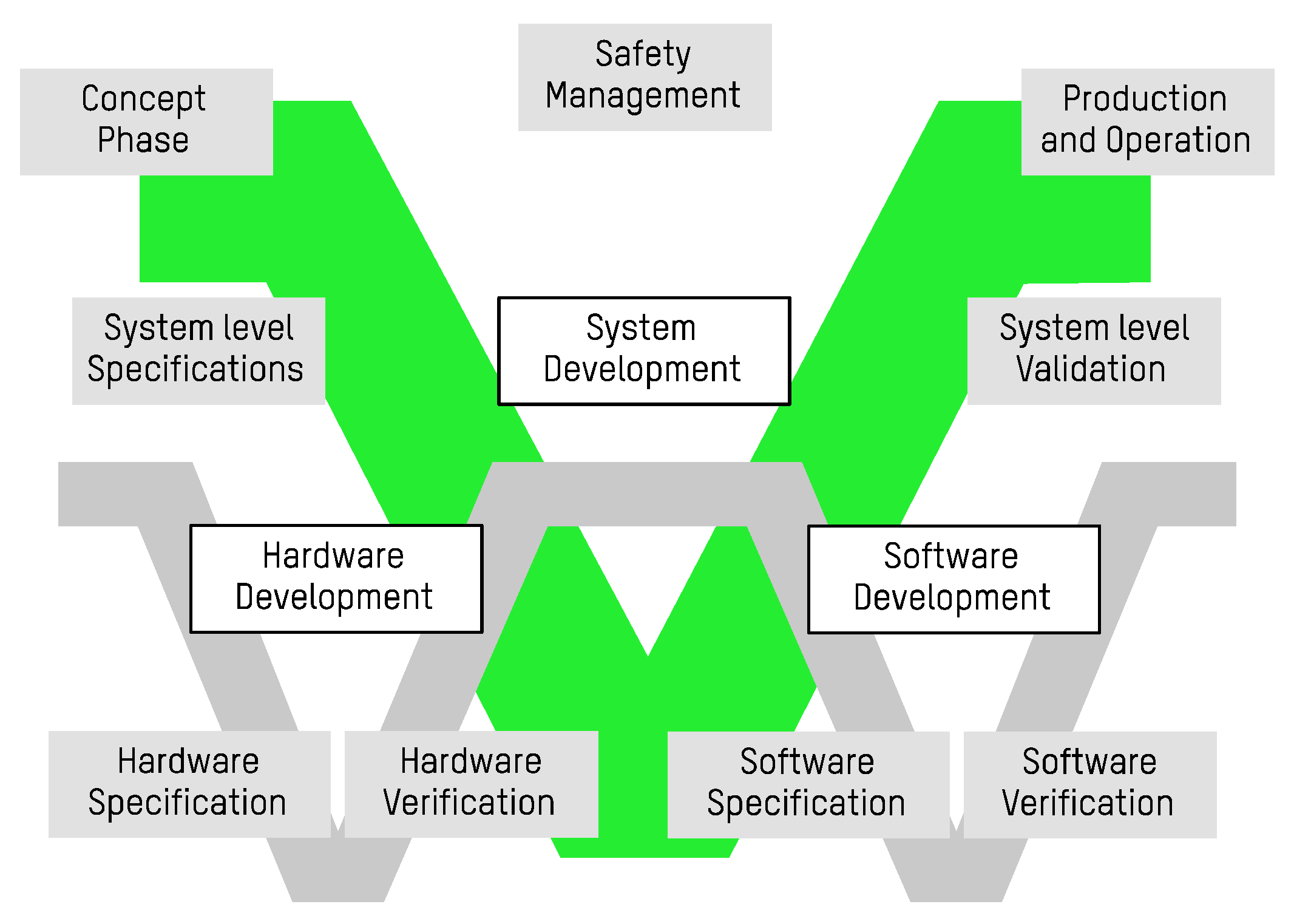
Battery management systems are protection systems and, therefore, they shall follow a safety-oriented design. In this framework, a review of the safety requirements and the methods applied in BMS design is proposed, which are supported by functional safety standards together with battery safety standards. This paper contributes a V-shaped design methodology (Figure 1) of an enhanced BMS complying with functional safety requirements for automotive lithium-based batteries.
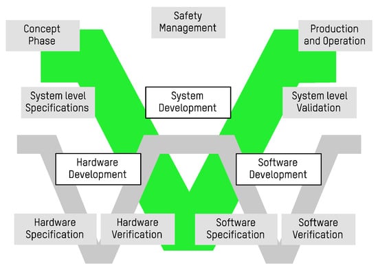
Figure 1.
Safety-oriented design methodology.
Among the several design and development methodologies, safety-related systems follow a methodology that prioritises integrity and safety over development time and cost. V-shaped methodology, as well as the waterfall model, is a sequential process that requires the completion of each activity to advance to the next task. However, unlike the waterfall model, V-shaped methodology is an iterative process, which is necessary to ensure that no errors are committed during the design. The V-shaped methodology consists of five stages: the concept phase, specifications, development, validation, and production and operation. Although it is not considered as a stage, safety management activity must be present in all stages, and it is crucial to supervise the product life cycle. Additionally, the development phase is decomposed into hardware and software developments, each with its own V-shaped methodology consisting of specification, development, and verification. At the lowermost tip of the V, the prototype or release is realised. The V-shaped methodology is iterative because if any fault occurs during the verification, validation, or production phases, the project can return to the hardware/software specifications, system level specification or concept phase, respectively, to amend the fault. The objective of the proposed methodology is to cover the existing gap in the design of most advanced BMS, also considering safety in all its aspects.
As a first step of the methodology, Section 2 comprises the concept phase and introduces a safety assessment of lithium-based batteries in automotive battery packs, that leads to the allocation of safety goals to be fulfilled by the BMS. As the second and third steps of the methodology, Section 3 gathers the technical safety requirements derived from these safety goals and the resulting design of the enhanced BMS slave (as part of the overall BMS). As the fourth and final step of the methodology, Section 4 describes the verification of the enhanced BMS Slave by means of a Failure Modes, Effects and Diagnostics Analysis. Finally, Section 5 summarises the obtained conclusions.
2. Concept Phase: Hazard and Risk Assessment, and Safety Goals Allocation
As a general definition, safety goals are top level objectives that the BMS must fulfil to ensure the safety of the lithium-based battery under control. They are derived from a hazard analysis and risk assessment of the specific automotive application under study and must be consistent to control the risk down to an acceptable level. The Automotive Safety Integrity Level (ASIL) is the risk classification defined by the ISO 26262 standard (functional safety standard for automotive industry). It is an adaptation of the Safety Integrity Level (SIL) used in IEC 61508 standard (functional safety standard for general applications). This classification helps in defining the previously cited necessary risk reduction. The ASIL is established by looking at the likelihood and the consequences of a hazard in the hazard and risk assessment.
The standard classifies the necessary risk reduction as: ASIL A, ASIL B, ASIL C, ASIL D and QM (Quality Management). ASIL D dictates the highest safety requirements on the function integration, achieving the greatest risk reduction, and ASIL A the lowest. Risks classified as QM must undergo a regular quality management design process.
In the next subchapters, a hazard analysis and risk assessment of the lithium-based battery for automotive application is carried out. For this purpose, a brief description of the application scenario is carried out and the safety issues concerning lithium-based batteries are considered. This assessment classifies the identified risks and infers the required ASIL. Finally, the safety goals are deduced and allocated.
2.1. Hazard Analysis
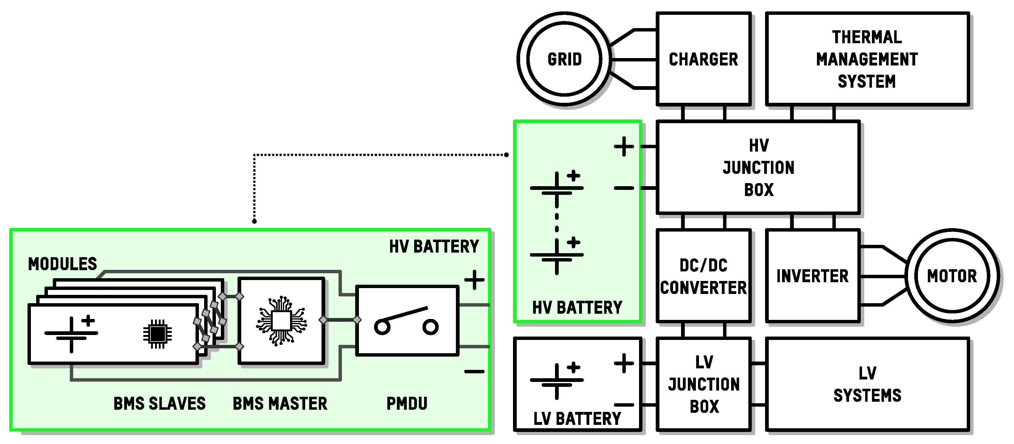
A lithium-based battery is the main energy source of a battery electric vehicle. It is part of the vehicle traction system and there are several devices connected to it, including the BMS in charge of controlling it. A block diagram of a battery electric vehicle traction system is depicted in Figure 2, which integrates a high voltage (HV) lithium-based battery and a low voltage (LV) lead-acid battery.

Figure 2.
Application scenario description.
The BMS is comprised, at the same time, of BMS Slaves (one at each module), a BMS Master and a power monitoring and disconnection unit (PMDU). BMS Slaves gather monitoring data from the cells and transmit them to the BMS Master. In addition, BMS Slaves include cell balancing circuits. Cell imbalances occur if cells in a battery are not homogeneously charged, when their maximum capacity differs from one another, or if either their cell internal or external circuit leakage currents are different among them. Cell imbalances promote cell overcharge and overdischarge, and also prevent the application from exploiting the full battery capacity. Consequently, cell balancing circuits and balancing algorithms need to be allocated to the BMS to overcome this issue. The BMS Master processes the data sent by the BMS Slaves and controls them to coordinate the measurements and to execute the balancing algorithm. The BMS Master also controls the PMDU, which holds the contactors for battery connection and disconnection to the application as well as fuses and a pre-charge circuit. During battery operation, the BMS connects the battery to the traction system and communicates battery relevant data. In the case of any safety concern, the BMS must interrupt the battery current. Furthermore, the BMS must include relevant battery parameter estimation algorithms [5], such as the State of Charge (SoC) [6] to determine the remaining capacity in the battery, the State of Health (SoH) [7] to estimate the capacity fade from the beginning of life, and the State of Power (SoP) [8] for an accurate power capability estimation. These advanced estimation algorithms are necessary to operate the battery and contribute to battery safety.
Lithium-based batteries have intrinsic safety concerns. The main parameters that can compromise their safety are temperature, voltage, current, mechanical damage, manufacturing pollution and even the number of serialised cells. These parameters delimit the so-called Safe Operation Area (SOA), whose thresholds vary depending on the battery constituents. When batteries are operated out of the SOA, secondary reactions begin which can quickly degrade cells or even start a fire.
The electrical and chemical behaviour of batteries is highly influenced by temperature [9]. When a battery is exposed to temperatures above 60 °C, hazardous secondary reactions begin. When a cell temperature is increased above the maximum temperature and the dissipation rate is enough to cool it down, it can endure the overtemperature event. However, if the temperature keeps increasing, a thermal runaway might be triggered.
A thermal runaway is a process where the heat generated by an exothermic reaction accelerates the reaction rate which, in turn, increases the heat generation rate. The thermal runaway is a temperature positive feedback that collapses the cell [10]. It begins by decomposing the solid electrolyte interphase layer. Then, the anode reacts with the electrolyte, the separator is melted, the electrodes are decomposed, and lastly, the electrolyte is decomposed. During a thermal runaway process, generated gasses build up the internal pressure of the cell [11]. Internal pressure can cause the cell rupture, liberating noxious gasses, fire, and deflagrations. When several cells are grouped in a module, a thermal runaway can be propagated by heat transfer [12]. Moreover, a thermal runaway can also generate internal short-circuits in the affected cell, therefore, it can also be propagated to electrically parallel-connected cells. The onset temperature of a thermal runaway decreases at higher cell voltages [13] and when lithium deposits are present in the cell anode [14]. The thermal runaway event ends when the reaction constituents are consumed.
On the other hand, chemical reaction kinetics of lithium-based batteries are reduced at low temperatures [15]. During cell charge, slow lithium intercalation and diffusion in the anode causes lithium plating [16]. When batteries are further misused at lower temperature ends, they can grow lithium deposits in the form of dendrites that eventually penetrate the separator and internally short-circuit the electrodes (except for lithium titanate (LTO) type batteries). Internal short-circuits can greatly increase battery heat generation and lead the affected cells to a thermal runaway. Battery power capabilities are decreased at low temperatures with the lowest temperature limit being the electrolyte freezing temperature, normally below −20 °C, at which the cell cannot be cycled [17].
The largest contributor to heat generation of a lithium-based battery is the current. Additionally, the current is also the second largest contributor to cell ageing [9,18]. An external short-circuit is the greatest exponent of battery overcurrent [10]. Moreover, in the case of batteries made of lithium metal anodes, such as Li-O2 and Li-Sulfur batteries [19], at high current rates lithium plating deposits are generated in the anode [20].
Regarding voltage, lithium-based batteries are overcharged if their terminal voltage is higher than the cell’s maximum voltage. Battery overcharge can either be caused by an excessive charge presence inside the cell, or by an excessive charge current. When a battery is being charged, lithium-ions and electrons are moving from the cathode to the anode. The overcharge occurs when the lithium-ions of the cathode are depleted [21]. The cathode becomes unstable after permanent crystallographic changes caused by the high oxidation potentials, leading the cathode to release oxygen that decomposes the electrolyte. Additionally, excessive intercalation of lithium-ions in the anode can cause lithium plating. During the overcharge process, side reactions release gas and heat, which can promote cell venting and fire [22]. The battery response to overcharges is related to the overcharge voltage, current, as well as the environmental conditions and battery constituents [23], among which the cathode is the most influent constituent. When thermal runaway occurs due to a battery overcharge, the event becomes more hazardous because of the additional energy stored. On the other hand, small overcharges at low charging rates can be overcome without fire, but overcharging the cell slightly and repeatedly will eventually trigger a thermal runaway [24].
In an overdischarge process of a lithium-based battery, graphite anodes are delithiated [25], which decomposes the solid electrolyte interphase layer and releases CO and CO2 gasses. Additionally, the copper collector becomes electronically incompatible with high anode potentials causing copper dissolution. The dissolved copper is deposited in the anode surface, growing dendrites that can occasionally short-circuit the cell. When a cell is overdischarged, the internal short-circuits are not very hazardous because of the low energy in the cell. Nevertheless, when the cell is recharged, the internal short-circuit behaves like a low value resistor [26] increasing the temperature of the cell, which can lead to a thermal runaway. If no short-circuit happens during the overdischarge, the cell is still functional and can be recharged. Further discharging the cell or consecutively overdischarging it increases the chances of an internal short-circuit. After the overdischarge, if the cell is recharged, the solid electrolyte interphase may be regenerated [25] but the anode resistance is also increased. Moreover, lithium-ions are consumed in the regeneration of the solid electrolyte interphase layer, permanently reducing the cell capacity.
Mechanical stresses on batteries can also cause internal short-circuits, either due to the penetration of the cell casing [27] or heavy forces applied to the battery in the form of vibrations or impacts [28]. In both cases, the electrodes are electrically connected, short-circuiting the cell and causing a huge energy release in a short time. Additionally, the electrodes are continuously expanding and contracting [29] during battery operation. After several electrical and thermal cycles, the electrodes can be displaced, which can cause them to come into contact and be short-circuited if they are not properly designed and manufactured. Furthermore, during cell manufacturing, any pollutant agent can contaminate the cell [10]. Pollutant agents may be deposited in the electrodes and grow in the form of dendrites, leading to an internal short-circuit.
As a conclusion, “fire, deflagration, and gases” are the intrinsic hazards related to lithium-based batteries. In addition to them, “electric shock” and “vehicle accident caused by loss of functionality” are other potential hazards when applying a high voltage battery in an electric vehicle application.
Most of the misuse events regarding the operation of a battery out of the SOA lead to hazards related to fire, deflagration, and gas emissions. The excessive heating of local components, such as cables or PCBs, can also cause them to ignite. Moreover, the liquid electrolytes typically used in lithium-based cells contain a mixture of organic solvents [29] (e.g., Ethylene Carbonate, Dimethyl Carbonate, Ethyl Methyl Carbonate, etc.) and a lithium salt, such as LiPF6, LiBF4 or LiClO4. If a cell leaks electrolyte, it can react with the ambient moisture [30] and generate hydrofluoric acid (HF), which is highly irritating [31]. Electrolyte gasses can also form explosive mixtures when mixed with air.
Serialised cells increase the voltage of the resultant battery. High voltage batteries present electrical risk, and any insulation fault between their live parts and accessible parts can lead to electric shock and arc formation.
Finally, the battery pack fulfils essential functions in an electric vehicle. The loss of any battery pack functionality during a critical scenario, such as driving on a highway at high speeds, can lead to accidents. The essential functions fulfilled by the battery are not limited to power sourcing and storing, but also data communication and coordination with the connected devices and, therefore, they must be ensured.
2.2. Risk Assessment
The risk assessment consists of listing the identified hazards and their causes, planning the measures that can be applied to prevent or mitigate the hazards and assessing the risk to identify the necessary risk reduction. The risk is assessed combining three individual parameters as recommended in the ISO26262 standard: severity (S), exposure (E), and controllability (C). Each parameter has different levels to qualitatively classify its contribution to the risk of the assessed hazard cause. The severity of the hazard is classified in four levels, from S0 (no injuries) to S3 (life-threatening injuries). The exposure to the hazard is classified in five levels, from E0 (incredible) to E4 (very probable). Finally, the controllability of the hazard is also classified in four levels, from C0 (controllable in general) to C3 (hard to control or uncontrollable).
The risk level is inferred from the severity, exposure, and controllability parameters by means of the risk graph matrix in Table 1. The risk graph matrix relates the tolerable risk and the necessary risk reduction, and the outcome is the ASIL applicable to the cause under assessment. Any combination with S0, E0 and C0 results in a QM requirement. When a requirement of QM applies, the risk is generally low, but must not be neglected. The design and development of the function to prevent or control the risk cause must, at a minimum, comply with a quality management system such as the one obtained from ISO 9001 or ISO/TS 16949 standard guidelines. The quality management system helps in preventing mistakes and controlling the design processes. As for the ASIL A to D requirements, in addition to the quality management system, ISO 26262 demands the inclusion of extensive analysis, processes and documentation to demonstrate that the designed function has the appropriate measures to reduce the risk in the required extent.

Table 1.
Risk graph matrix of the ISO26262.
Regarding the risk assessment of automotive lithium-based batteries, Table 2 lists all the identified hazards and some of their causes. The main causes are disaggregated down to the causes at the component level, including as much details as possible to correctly identify the roots of the hazard. Deriving all the causes and details can be made by induction or deduction. The induction approach requires identifying every possible cause of failure and evaluating if it leads to a given hazard. The deduction approach, in turn, is achieved by thinking about how a given hazard can be caused and decomposing the cause into failure modes. Then, preventive and mitigation measures not related with the E/E/PE systems are planned. Preventive measures aim to reduce the hazard exposure, whereas mitigation measures try to reduce the severity when the hazard occurs.
Table 2.
Hazard and risk analysis (extracted sample of various spread rows).
After the hazard and risk analysis, Table 3 assesses the risk of each hazard cause. The severity, exposure, and controllability parameters are assigned along with their rationale considering the already planned preventive and mitigation measures. The assignation is qualitative and corresponds to the authors judgement, along with the given rationale, provided that there is no public quantitative data to calculate the necessary risk reduction.
Table 3.
Risk assessment.
2.3. Safety Goals Definition
In case the allocated non-E/E/PE preventive and mitigation measures are not sufficient, then safety goals are planned for the E/E/PE safety-related system, i.e., the BMS in the present case. Safety goals (SG) are presented in Table 4 and allocated to the causes in Table 3.
Table 4.
Safety goals definition.
Safety goals are then derived to satisfy safety requirements, a safety architecture, and the diagnostics. The extent of the specifications and the diagnostics depends on the assigned ASIL, for example, if the ASIL of a safety goal is underrated it could not meet the true necessary risk reduction, whereas overrating the ASIL could greatly increase development costs.
3. Development Phase: Functional/Technical Requirements and Design
The overall BMS needs to fulfil the safety goals of Table 4. It shall integrate and communicate with up to 16 enhanced BMS Slaves. As part of a top-level specification, the overall BMS must follow the following safety strategy to fulfil the established safety goal at all times. If a safety goal is about to be violated, the BMS must lead the battery to the safe state. The safe state is the operational state where hazards cannot happen. In general, the battery is in the safe state when no current flows through it. This can be achieved either by disconnecting the battery from the traction system, or by setting the charge and discharge power of the traction system to zero. Conversely, the safe state should not be activated when the vehicle is at high speed. Unless it is critical, i.e., fire is imminent or it has been detected, the vehicle must enter an emergency state until the vehicle can be safely stopped. For this purpose, three error categories are proposed: tolerable errors, severe errors and fatal errors. Tolerable errors must only be noticed to initiate the call for maintenance, severe errors must activate the emergency state, and fatal errors must directly activate the safe state, without going first to the emergency state.
Consequently, the BMS must detect the hazardous event and reach the safe state inside the fault tolerant time interval. The fault tolerant time interval of the enhanced BMS is one second. This relatively long time has been chosen considering there are no evidences of thermal runaway caused by short, single abusive events [10]. In parallel, the BMS must scan its resources periodically to find faults that in combination with other faults can violate a safety goal. The considered period for multiple failure diagnosis is either eight hours or every time prior to a vehicle charge.
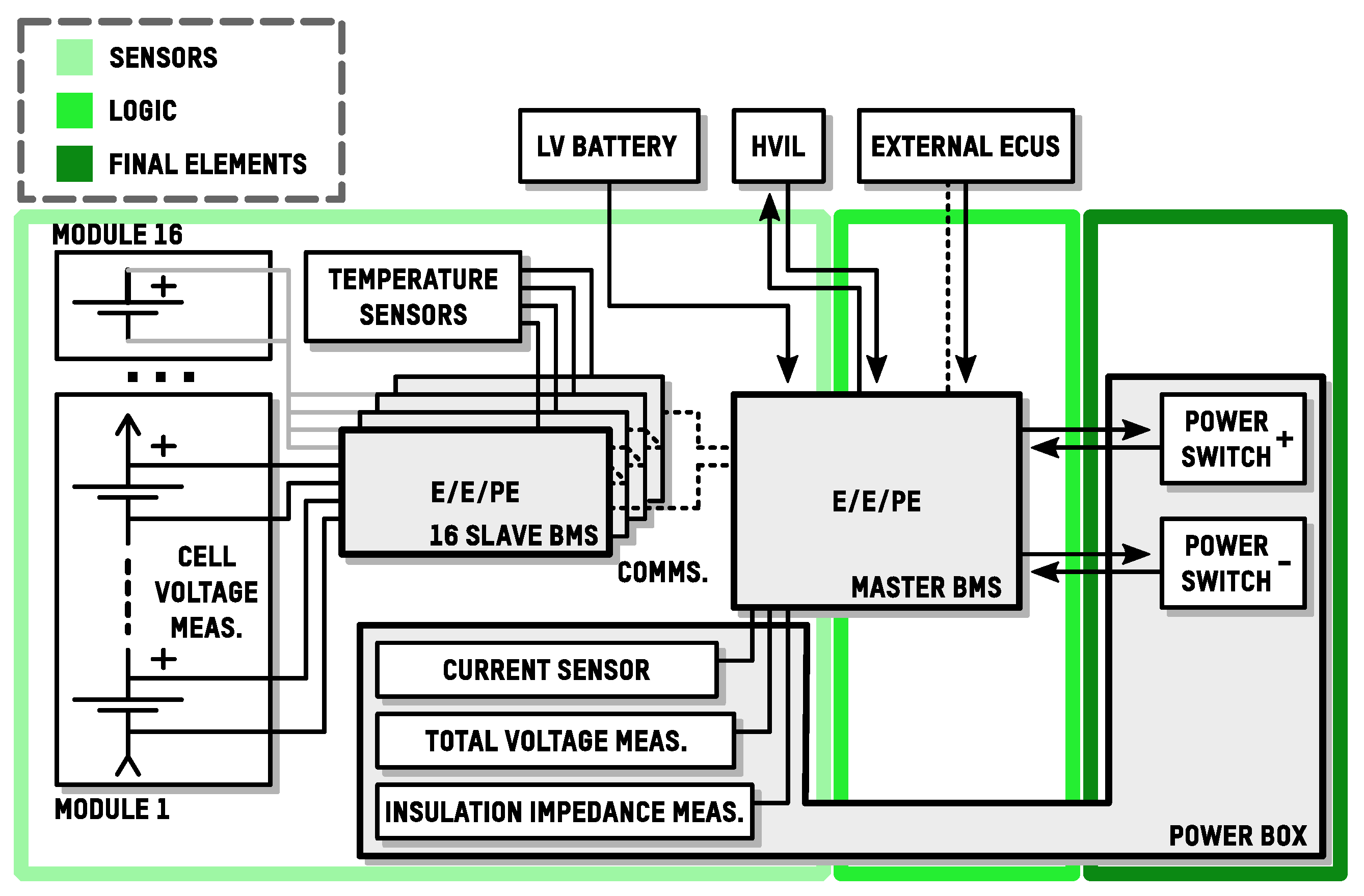
Regarding the safety architecture, Figure 3 shows the simplified architecture defined for the overall BMS. As it is depicted, the BMS Slaves are supplied directly from the cells, whereas the BMS Master is supplied from the 12/24 V low voltage (LV) battery. The BMS Master performs the current sensing, measures the battery total voltage, monitors the insulation impedance of the high voltage circuit, takes part in the high voltage interlock circuit (HVIL), controls redundant power switches for battery isolation and protection and, finally, communicates with external electronic control units (ECUs).
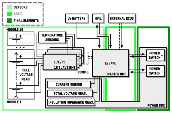
Figure 3.
Technical safety architecture.
Advanced estimation algorithms, such as SoC, SoH and SoP [6,7,8], or internal short-circuit detection algorithms [32], are highly desirable diagnostics for battery misuse prevention as long as they are accurately tuned [33] for the used cell. Consequently, they should be allocated to either the BMS Master or an external ECU like an energy management system (EMS) or shared between both. In case advanced estimation algorithms are integrated in the BMS Master, special attention should be given to the software failure modes (e.g., soft or hard errors, out of boundary conditions, and stack overflow), and their integration in a separate non-safety-critical processor should be considered.
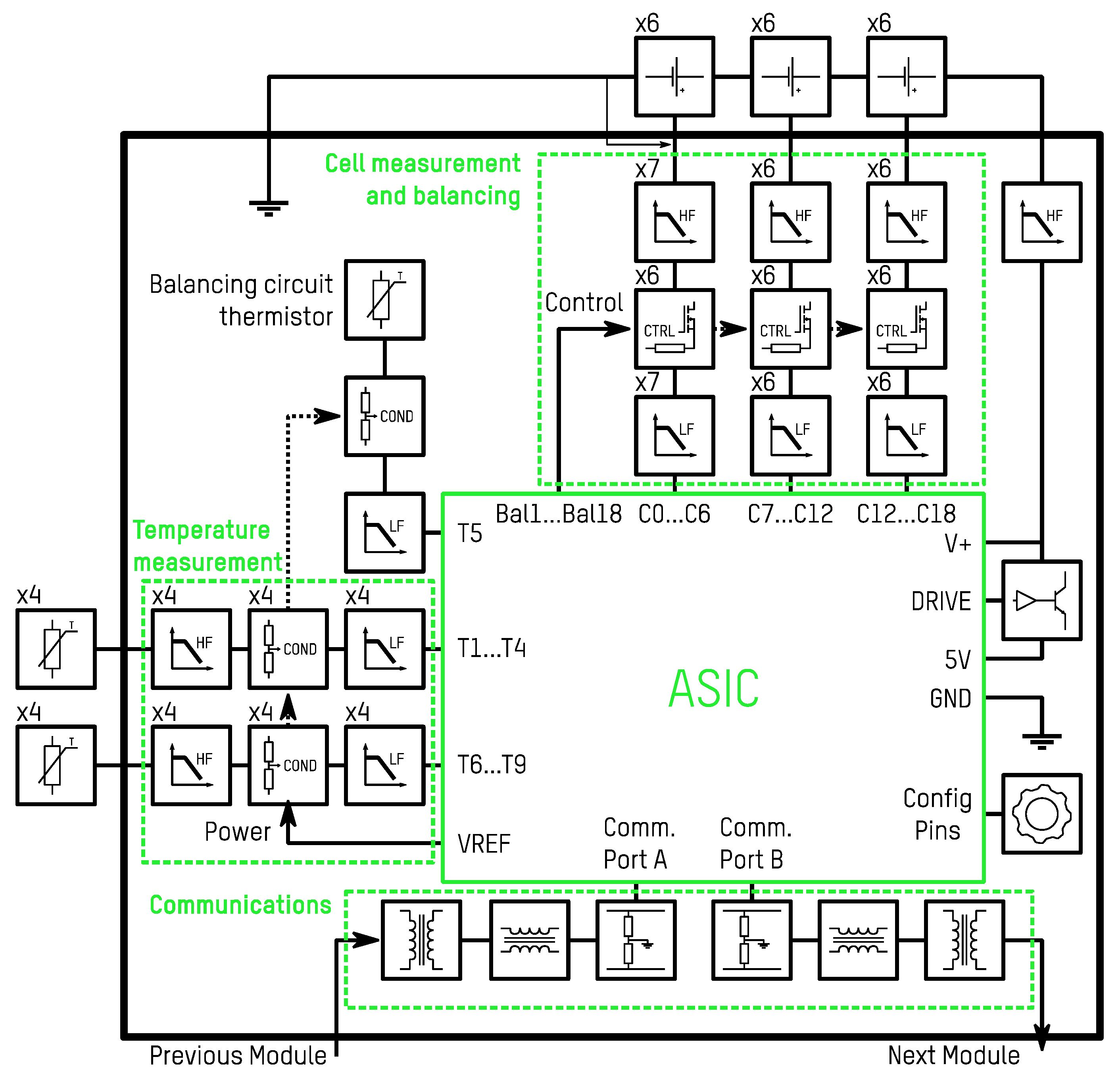
The enhanced BMS Slave safety architecture is presented in Figure 4. It is composed of four main circuits: cell measurement and balancing [34], temperature measurement, communications, and the Application Specific Integrated Circuit (ASIC). The ASIC is a state-of-the-art and off-the-shelf battery management IC designed for functional safety-oriented applications. All the interfaces include high frequency (HF) filters to comply with EMC standards. The cell measurement circuit includes an on-board thermistor to monitor the cell balancing circuit temperature. The temperature measurement circuit comprises NTC or PTC type sensors, and includes HF and LF filters, and conditioning circuits to adapt the resistor value to a voltage signal. A configurable temperature measurement is considered, where single-ended redundant or differential modes can be selected for each pair of temperature inputs. In the case that the environmental noise does not allow a safe operation, a combination of both, i.e., single redundant and differential modes, can be used to ensure precision as well as safety. The communication circuit provides galvanic isolation and includes resistor endings to match the characteristic impedance. Finally, the ASIC must have the recommended power supply and peripheral components for the hardware configuration and its operation. All the elements in the BMS Slave are safety-relevant to comply with the safety goals.
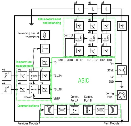
Figure 4.
Technical safety architecture of the enhanced BMS Slave.
The safety requirements are aligned to the architecture in Figure 4 and describe the detailed functionalities and the technical aspects to realise a feasible safety concept of the element under development. The most relevant technical safety requirements of the enhanced BMS Slave are collected in Table 5.
Table 5.
Technical safety requirements of the enhanced BMS Slave.
Finally, the applicable safety analyses and measures are defined. To this end, safety mechanisms are derived from a Failure Modes and Effects Analysis (FMEA). Safety mechanisms are elements or functions intended to prevent or detect failures in the hardware or the software of the element under design. An FMEA is an inductive safety analysis which identifies and describes the failures that can occur in the system. Finally, it must be argued how the failure is avoided or detected according to the defined safety mechanism. Table 6 presents the most relevant entries of the FMEA carried out for the enhanced BMS Slave according to the technical safety architecture and technical safety requirements.
Table 6.
Failure Modes and Effects Analysis (FMEA) of the enhanced BMS Slave.
Consequently, Table 7 summarises the most relevant employed safety mechanisms. State-of-the-art ASICs also include several internal safety mechanisms that enable their integration in functional safety-oriented applications.
Table 7.
Safety mechanisms of the enhanced BMS Slave.
As a result of the described requirements, architecture and safety mechanisms, the design of the enhanced BMS slave was carried out. A prototype of the enhanced BMS is presented in Figure 5.

Figure 5.
Developed enhanced battery management system slave prototype complying with functional safety ASIL C requirements.
4. Verification by Failure Modes, Effects and Diagnostics Analysis
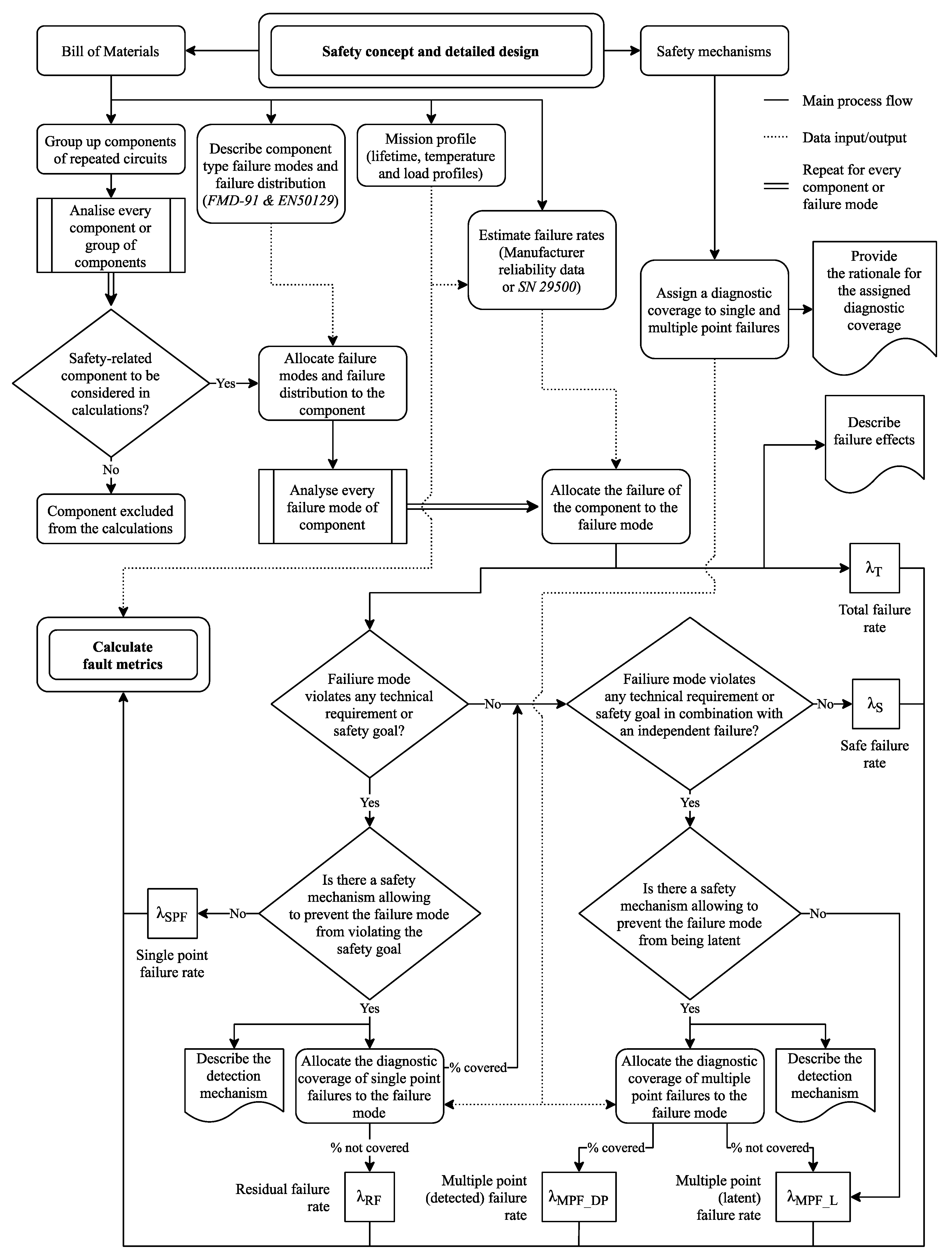
The verification process of a safety-related system does not only consist of testing activities [35]. In this work, the verification by means of a Failure Modes, Effects and Diagnostics Analysis (FMEDA) is described. The FMEDA is an inductive safety analysis which consists of analysing the failure modes of every hardware component and checking the suitability of the design according to random failures. This safety analysis is carried out to highlight the circuit vulnerabilities and calculate the random hardware failure rate. The procedure followed to carry out the FMEDA is depicted in Figure 6. The procedure begins by listing all the components in the design and the planned safety mechanisms. The failure modes, failure rates and failure rate distributions are derived for every component. Furthermore, the diagnostic coverage of the safety mechanisms is also assessed. Finally, the effects of every component failure mode are analysed. The following paragraphs describe the details of the followed procedure for completing the FMEDA.
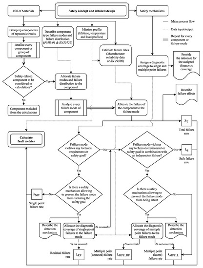
Figure 6.
Procedure followed for the realization of the FMEDA.
Hardware random failure rates are obtained either from reliability data sources [35,36,37] or measured from testing. However, measuring the failure rates requires accelerated testing of a substantial number of components [38]. Due to the elevated costs of measuring the failure rate for component manufacturers, they are mostly acquired from the reliability data sources. Failure rates are expressed in Failures in Time (FIT), which represent the number of failures expected in 109 h. The failure rate of every component is heavily related to the temperature of operation and load profiles, for which the mission profile must be first specified. Higher temperatures penalise the failure rate of components. For this analysis, an operation temperature of 40 °C was considered, aiming to cover a very demanding scenario without overestimating the failure rate.
Regarding the failure modes of safety-related components, they must be analysed to identify whether they would violate a safety goal. Hardware failure modes can be found in standards [35,39,40,41] or can be estimated through analysis. The former is the recommended route, but the latter may be necessary for most integrated circuits or other than ordinary components. For the analysis, the FMD-91 and EN 50129 standards were used, which detail the failure modes and failure rate distribution of most common components. Although the mentioned standards are not usually used in automotive applications, they have been used because they provide a very accurate failure mode disaggregation.
The diagnostic coverage is the effectiveness of the diagnostics, which is the number of detectable failure modes compared with the total failure modes. The diagnostic coverage expresses the percentage of detectable failure modes of a given component or set of components. Safety mechanisms can decrease the failure rate of the detected dangerous failures by their diagnostic coverage. A rationale must be given for the selected diagnostic coverage for every safety mechanism.
The next step is to analyse every failure mode of each component. It must be assessed whether the failure mode is dangerous, and whether it may violate the safety objective by itself (single point faults), or in combination with other component faults (multiple point faults). For this purpose, the failure mode effects must be described. In the case where there is a safety mechanism to detect the failure mode, a rationale of the detection must also be provided. Consequently, the diagnostic coverage must be considered for the failure rate calculations. After running through the procedure, the failure rate of each failure mode is disaggregated as:
- λt: total failure rate; every safety-related failure mode contributes to the total failure rate.
- λs: safe failure rate; fraction of the failure rate that is not dangerous.
- λSP: single point failure rate; failure rate contribution of undetected dangerous faults.
- λRF: residual failure rate; failure rate contribution of the uncovered percentage of a detected fault.
- λMP_L: multiple point latent failure rate; failure rate contribution of the uncovered percentage of detected multiple point faults or the contribution of undetected multiple point faults.
- λMP_DP: multiple point detected failure rate; failure rate contribution of the covered percentage of detected multiple point faults.
The dangerous failure rate is controlled by the establishment of a maximum failure rate and fault metrics. The fault metrics indicate the percentage of a single and multiple point dangerous failure rate over the total failure rate. The single-point fault metric (SPFM) is described by (1), and it is an indicator of the suitability of the diagnostics and measures included to detect or prevent direct dangerous faults. On the other hand, the latent fault metric (LFM) is calculated with (2), and similarly, represents the extent of the avoided dangerous faults when one or more components have already failed. According to the ISO 26262 standard, the target SPFM for the ASIL C safety goals is 97%, whereas the target LFM is 80%.
The probabilistic metric of hardware failures (PMHF) is an estimation of the average probability of failures per hour of the components that fulfil a given safety goal. The PMHF is calculated according to (3), where Tlifetime is the overall application lifetime in hours. The PMHF must be evaluated for the full safety goal and must be below the threshold given by the ISO 26262 standard. The target PMHF of enhanced BMS Slaves has been established as 65 % of the overall PMHF required for an ASIL C safety goal, which is 100 FIT. This fraction of the overall PMHF, in turn, must be shared among the total serialised enhanced BMS Slaves. As a total of 16 serialised enhanced BMS Slaves are considered, each enhanced BMS Slave shall have a PMHF under 4 FIT. This PMHF objective is arbitrary but has been determined considering the PHMF of the BMS Master and PMDU shall also be achievable to complete each safety goal.
The obtained failure rates, fault metrics and PMHF of the voltage and temperature monitoring are presented in Table 8. Although the FMEDA can be completed for each individual safety goal, a conservative approach has been taken and the presented results encompass all the BMS Slave applicable safety goals, provided that most sub-circuits are common. According to the obtained results, the enhanced BMS Slave is suitable for the accomplishment of the ASIL C safety goals.
Table 8.
Failure rates and fault metrics obtained in the FMEDA of the enhanced BMS Slave.
5. Conclusions
This paper contributes an ISO26262 compliant safety-oriented design and verification methodology for battery management systems (BMS). The lithium-based battery safety concerns were analysed to show the short and long-term hazards of using batteries in automotive applications.
A hazard and risk assessment has shown that an automotive BMS for traction batteries should satisfy at least an ASIL C rating in order to achieve the necessary risk reduction for safe battery operation. A safety architecture was realised for the overall system which considers a three-subsystem topology, composed of 16 BMS Slaves to monitor high voltage batteries (up to 1000 V), a BMS Master and a power monitoring and disconnection unit (PMDU). Most relevant requirements, preventive and mitigation measures, and safety mechanisms are presented to comply with ASIL C requirements for enhanced BMS Slaves.
Finally, the presented BMS Slave was verified by assessing its failure rate and fault metrics. The failure rate and fault metrics of the enhanced BMS Slave were assessed by a Failure Modes, Effects and Diagnostics Analysis (FMEDA). A maximum probabilistic metric of hardware failures (PMHF) of 65 Failures in Time (FIT) was allocated to 16 BMS Slaves, whilst a maximum failure rate of 35 FIT was allocated to the BMS Master and PMDU to fulfil the ASIL C safety goals. Additionally, the single-point fault metric (SPFM) and the latent fault metric (LFM) must be above 97% and 80%, respectively. The methodology applied for the FMEDA was described and applied to the enhanced BMS Slave, resulting in a PMHF of 3.94 FIT for a single BMS Slave, an SPFM of 99.1% and an LFM of 88%. Consequently, 16 BMS Slaves had a PMHF of 63.04 FIT, representing an enhancement of 3% below the 65 FIT threshold, demonstrating an ASIL C capability and the suitability of the design based on the presented methodology.
Author Contributions
Writing—original draft preparation, D.M.; writing—review and editing, M.G.; validation, J.A.C.; supervision, J.C. All authors have read and agreed to the published version of the manuscript.
Funding
This research received no external funding.
Conflicts of Interest
The authors declare no conflict of interest.
References
- International Energy Agency. Global EV Outlook 2020 Entering the Decade of Electric Drive; International Energy Agency: Paris, France, 2020. [Google Scholar] [CrossRef]
- Bloomberg. Battery Fires Sting BMW, Ford, others as EVs Take Off; Bloomberg: New York, NY, USA, 2020. [Google Scholar]
- Lambert, F. Hyundai to Recall 77,000 Kona Electric Cars over Risk of Battery Fire, Fights LG Chem over Cause—Electrek. 2020. Available online: https://electrek.co/2020/10/12/hyundai-recall-77000-kona-electric-cars-risk-battery-fire-lg-chem/ (accessed on 10 November 2020).
- Wikipedia. Plug-in Electric Vehicle Fire Incidents. Available online: https://en.wikipedia.org/wiki/Plug-in_electric_vehicle_fire_incidents (accessed on 10 November 2020).
- Cheng, K.W.E.; Divakar, B.P.; Wu, H.; Ding, K.; Ho, H.F. Battery-Management System (BMS) and SOC Development for Electrical Vehicles. IEEE Trans. Veh. Technol. 2010, 60, 76–88. [Google Scholar] [CrossRef]
- Li, Y.; Wei, Z.; Xiong, B.; Vilathgamuwa, D.M. Adaptive Ensemble-Based Electrochemical-Thermal-Degradation State Estimation of Lithium-Ion Batteries. IEEE Trans. Ind. Electron. 2021, 1. [Google Scholar] [CrossRef]
- Ruan, H.; He, H.; Wei, Z.; Quan, Z.; Li, Y. State of Health Estimation of Lithium-ion Battery Based on Constant-Voltage Charging Reconstruction. IEEE J. Emerg. Sel. Top. Power Electron. 2021, 1. [Google Scholar] [CrossRef]
- Wei, Z.; Zhao, J.; Xiong, R.; Dong, G.; Pou, J.; Tseng, K.J. Online Estimation of Power Capacity with Noise Effect Attenuation for Lithium-Ion Battery. IEEE Trans. Ind. Electron. 2018, 66, 5724–5735. [Google Scholar] [CrossRef]
- Ecker, M.; Sabet, P.S.; Sauer, D.U. Influence of operational condition on lithium plating for commercial lithium-ion batteries—Electrochemical experiments and post-mortem-analysis. Appl. Energy 2017, 206, 934–946. [Google Scholar] [CrossRef]
- Feng, X.; Ouyang, M.; Liu, X.; Lu, L.; Xia, Y.; He, X. Thermal runaway mechanism of lithium ion battery for electric vehicles: A review. Energy Storage Mater. 2017, 10, 246–267. [Google Scholar] [CrossRef]
- Maloney, T. Lithium Battery Thermal Runaway Vent Gas Analysis. 2016. Available online: https://www.fire.tc.faa.gov/pdf/TC-15-59.pdf (accessed on 10 November 2020).
- Lamb, J.; Orendorff, C.J.; Steele, L.A.M.; Spangler, S.W. Failure propagation in multi-cell lithium ion batteries. J. Power Sources 2015, 283, 517–523. [Google Scholar] [CrossRef] [Green Version]
- Al Hallaj, S.; Maleki, H.; Hong, J.; Selman, J. Thermal modeling and design considerations of lithium-ion batteries. J. Power Sources 1999, 83, 1–8. [Google Scholar] [CrossRef]
- Golubkov, A.W.; Scheikl, S.; Planteu, R.; Voitic, G.; Wiltsche, H.; Stangl, C.; Fauler, G.; Thaler, A.; Hacker, V. Thermal runaway of commercial 18650 Li-ion batteries with LFP and NCA cathodes—Impact of state of charge and overcharge. RSC Adv. 2015, 5, 57171–57186. [Google Scholar] [CrossRef] [Green Version]
- Ge, H.; Aoki, T.; Ikeda, N.; Suga, S.; Isobe, T.; Li, Z.; Tabuchi, Y.; Zhang, J. Investigating Lithium Plating in Lithium-Ion Batteries at Low Temperatures Using Electrochemical Model with NMR Assisted Parameterization. J. Electrochem. Soc. 2017, 164, A1050–A1060. [Google Scholar] [CrossRef]
- Huang, C.; Surampudi, S. Performance Characteristics of Lithium Ion Cells for Low Temperature Applications. NASA Rep. 2010, 41–46. Available online: https://trs.jpl.nasa.gov/bitstream/handle/2014/19016/98-0185.pdf?sequence=1 (accessed on 10 March 2021).
- Huang, C.-K.; Sakamoto, J.S.; Wolfenstine, J.; Surampudi, S. The Limits of Low-Temperature Performance of Li-Ion Cells. J. Electrochem. Soc. 2000, 147, 2893. [Google Scholar] [CrossRef] [Green Version]
- Li, J.; Murphy, E.; Winnick, J.; Kohl, P. Studies on the cycle life of commercial lithium ion batteries during rapid charge–discharge cycling. J. Power Sources 2001, 102, 294–301. [Google Scholar] [CrossRef]
- Shen, X.; Liu, H.; Cheng, X.-B.; Yan, C.; Huang, J.-Q. Beyond lithium ion batteries: Higher energy density battery systems based on lithium metal anodes. Energy Storage Mater. 2018, 12, 161–175. [Google Scholar] [CrossRef]
- Takeda, Y.; Yamamoto, O.; Imanishi, N. Lithium Dendrite Formation on a Lithium Metal Anode from Liquid, Polymer and Solid Electrolytes. Electrochemistry 2016, 84, 210–218. [Google Scholar] [CrossRef] [Green Version]
- Ohsaki, T.; Kishi, T.; Kuboki, T.; Takami, N.; Shimura, N.; Sato, Y.; Sekino, M.; Satoh, A. Overcharge reaction of lithium-ion batteries. J. Power Sources 2005, 146, 97–100. [Google Scholar] [CrossRef]
- Mauger, A.; Julien, C.M. Critical review on lithium-ion batteries: Are they safe? Sustainable? Ionics 2017, 23, 1933–1947. [Google Scholar] [CrossRef] [Green Version]
- Doughty, D.H.; Roth, E.P. A General Discussion of Li Ion Battery Safety. Electrochem. Soc. Interface 2012, 21, 37–44. [Google Scholar] [CrossRef] [Green Version]
- Xu, F.; He, H.; Liu, Y.; Dun, C.; Ren, Y.; Liu, Q.; Wang, M.-X.; Xie, J. Failure Investigation of LiFePO4 Cells under Overcharge Conditions. J. Electrochem. Soc. 2012, 159, A678–A687. [Google Scholar] [CrossRef]
- Guo, R.; Lu, L.; Ouyang, M.; Feng, X. Mechanism of the entire overdischarge process and overdischarge-induced internal short circuit in lithium-ion batteries. Sci. Rep. 2016, 6, 30248. [Google Scholar] [CrossRef] [Green Version]
- Brand, M.; Glaser, S.; Geder, J.; Menacher, S.; Obpacher, S.; Jossen, A.; Quinger, D. Electrical safety of commercial Li-ion cells based on NMC and NCA technology compared to LFP technology. World Electr. Veh. J. 2013, 6, 572–580. [Google Scholar] [CrossRef]
- Lamb, J.; Orendorff, C.J. Evaluation of mechanical abuse techniques in lithium ion batteries. J. Power Sources 2014, 247, 189–196. [Google Scholar] [CrossRef]
- Sahraei, E.; Campbell, J.; Wierzbicki, T. Modeling and short circuit detection of 18650 Li-ion cells under mechanical abuse conditions. J. Power Sources 2012, 220, 360–372. [Google Scholar] [CrossRef]
- Ruiz, V.R.; Pfrang, A.; Kriston, A.; Omar, N.; Bossche, P.V.D.; Boon-Brett, L. A review of international abuse testing standards and regulations for lithium ion batteries in electric and hybrid electric vehicles. Renew. Sustain. Energy Rev. 2018, 81, 1427–1452. [Google Scholar] [CrossRef]
- Larsson, F.; Andersson, P.; Blomqvist, P.; Mellander, B.-E. Toxic fluoride gas emissions from lithium-ion battery fires. Sci. Rep. 2017, 7, 1–13. [Google Scholar] [CrossRef]
- Hydrofluoric Acid. Available online: https://pubchem.ncbi.nlm.nih.gov/compound/hydrofluoric_acid (accessed on 17 May 2021).
- Hu, J.; He, H.; Wei, Z.; Li, Y. Disturbance-Immune and Aging-Robust Internal Short Circuit Diagnostic for Lithium-Ion Battery. IEEE Trans. Ind. Electron. 2021, 1. [Google Scholar] [CrossRef]
- Bian, X.; Wei, Z.; He, J.; Yan, F.; Liu, L. A Two-Step Parameter Optimization Method for Low-Order Model-Based State-of-Charge Estimation. IEEE Trans. Transp. Electrif. 2020, 7, 399–409. [Google Scholar] [CrossRef]
- Lin, K.; Chen, Y.; Liu, Y.; Zhang, B. Reliability Prediction of Battery Management System for Electric Vehicles Based on Accelerated Degradation Test: A Semi-Parametric Approach. IEEE Trans. Veh. Technol. 2020, 69, 12694–12704. [Google Scholar] [CrossRef]
- Department of Commerce, US. Failure Mode/Mechanism Distributions (FMD-91); Department of Commerce US: Washington, DC, USA, 1991. [Google Scholar]
- Department of Defense of the USA. Military Handbook MIL-HDBK-217F; Department of Defense of the USA: Washington, DC, USA, 1991. [Google Scholar]
- Siemens AG. Siemens Company Standard SN29500 (Version 6.0). Failure Rates of Electronic Components. Siemens Tech Liaison Stand; Siemens AG: Munich, Germany, 1999. [Google Scholar]
- Smith, D.J. Reliability, Maintainability and Risk; Elsevier: Amsterdam, The Netherlands, 2011; pp. 29–37. [Google Scholar]
- EN 50129:2018. Railway Applications—Communication, Signalling and Processing Systems—Safety Related Electronic Systems for Signalling. Available online: https://standards.iteh.ai/catalog/standards/clc/f6548cc3-5885-43aa-8654-9e71383b892e/en-50129-2018 (accessed on 17 May 2021).
- IEC TR 62380. Reliability Data Handbook—Universal Model for Reliability Prediction of Electronics Components, PCBs and Equipment. Test; Swedish Institute for Standards: Stockholm, Sweden, 2004; pp. 1–7. [Google Scholar]
- ISO 26262. Road Vehicles—Functional Safety—All Parts; ISO: Geneva, Switzerland, 2018. [Google Scholar]

Publisher’s Note: MDPI stays neutral with regard to jurisdictional claims in published maps and institutional affiliations. |
© 2021 by the authors. Licensee MDPI, Basel, Switzerland. This article is an open access article distributed under the terms and conditions of the Creative Commons Attribution (CC BY) license (https://creativecommons.org/licenses/by/4.0/).