1. Introduction
The China Fusion Engineering Test Reactor (CFETR) is a new tokamak reactor independently designed and developed by China with international cooperation. It is a major project to advance the research of the next generation superconducting fusion reactor based on ITER technologies. It will provide experimental data for commercial fusion reactors in the future [
1]. The blanket is one of the important components of CFETR. The main functions of the cladding are as follows: to generate tritium fuel for the fusion reaction of CFETR, to take away the radiation of plasma and the heat of nuclear reaction, and to protect the superconducting coil from heat and radiation damage [
1].
Currently, there are three alternative designs for the CFRETR blanket. The first is the water-cooled ceramic breeder blanket (WCCB), using water as coolant. The advantage is that the physical properties and flow parameters of water are well developed, such as the cooling water parameters of pressurized water reactor can be directly used. The disadvantages are also well known, such as the possibility of critical heat flux density (CHF) and loss of coolant accident (LOCA) accidents. The second is the helium-cooled solid blanket (HCSB), using helium gas as a coolant. The advantage is that helium is chemically stable and CHF does not occur because of gas form, but helium can be relatively expensive. The first two blankets are solid blankets with solid breeders and a solid multiplier in the form of pebble beds. The third blanket is the liquid lead–lithium blanket, using eutectic Pb-Li as a breeder and multiplier. The liquid blanket has a good tritium breeder capability and can provide the lithium and other proliferating materials in real time, without the need for regular disassembly and replacement like the solid blanket. However, the liquid metal introduces the complex Magneto Hydro Dynamics (MHD) effects that need to be addressed [
1,
2,
3,
4].
All these three types of blankets are structurally complex [
2,
3,
4]. The complex structure brings great challenges to the thermal hydraulics analysis and safety issues. Jiang et al. [
3] conducted three-dimensional (3D) CFD analysis on one module of WCCB. The number of nodes for this whole blanket module is 37574900, which is considerable. The temperature field, distribution of mass flow rate and coolant pressure drop were calculated. Fan et al. [
5] developed an optimized CFD method to perform 3D CFD analysis on a blanket module in order to reduce the computational load. However, the number of whole blanket nodes is huge and the simplified model may induce certain errors. Lian et al. [
4] analyzed two LOCAs under ITER-like conditions for the optimized CFETR HCSB. The results showed that complex safety systems are needed to ensure those accidents do not damage the blanket and vacuum vessel. Cui et al. [
6] studied the loss of flow accident (LOFA) of WCCB. The results of this study demonstrate that, under transient conditions, the current blanket design cannot ensure full safety conditions.
All above studies show that coolant-cooled blankets are complicated and fragile. Therefore, a more robust blanket design should be considered. Heat pipes have been used in fission reactor design. Compared with the coolant cooling reactor, the heat pipe cooling reactor has the following advantages: better heat transfer performance, more compact structure layout, fewer auxiliary systems [
7]. In this study, a new heat pipe cooled blanket is proposed. The primary numerical simulation of the heat cooled blanket is conducted and its feasibility is verified.
In this paper, the WCCB studied by Jiang et al. [
3] was taken as the comparison object, and the nuclear thermal parameters and blanket structure parameters of WCCB described in Jiang’s paper were used. The blanket tritium breeder layer and neutron multiplier layer were consistent with Jiang’s WCCB, and the coolant tubes in WCCB were replaced by heat pipes. The temperature distribution of the heat pipe cooled blanket was calculated and analyzed by numerical simulation.
2. Methods
The structure design is mainly based on WCCB [
3].
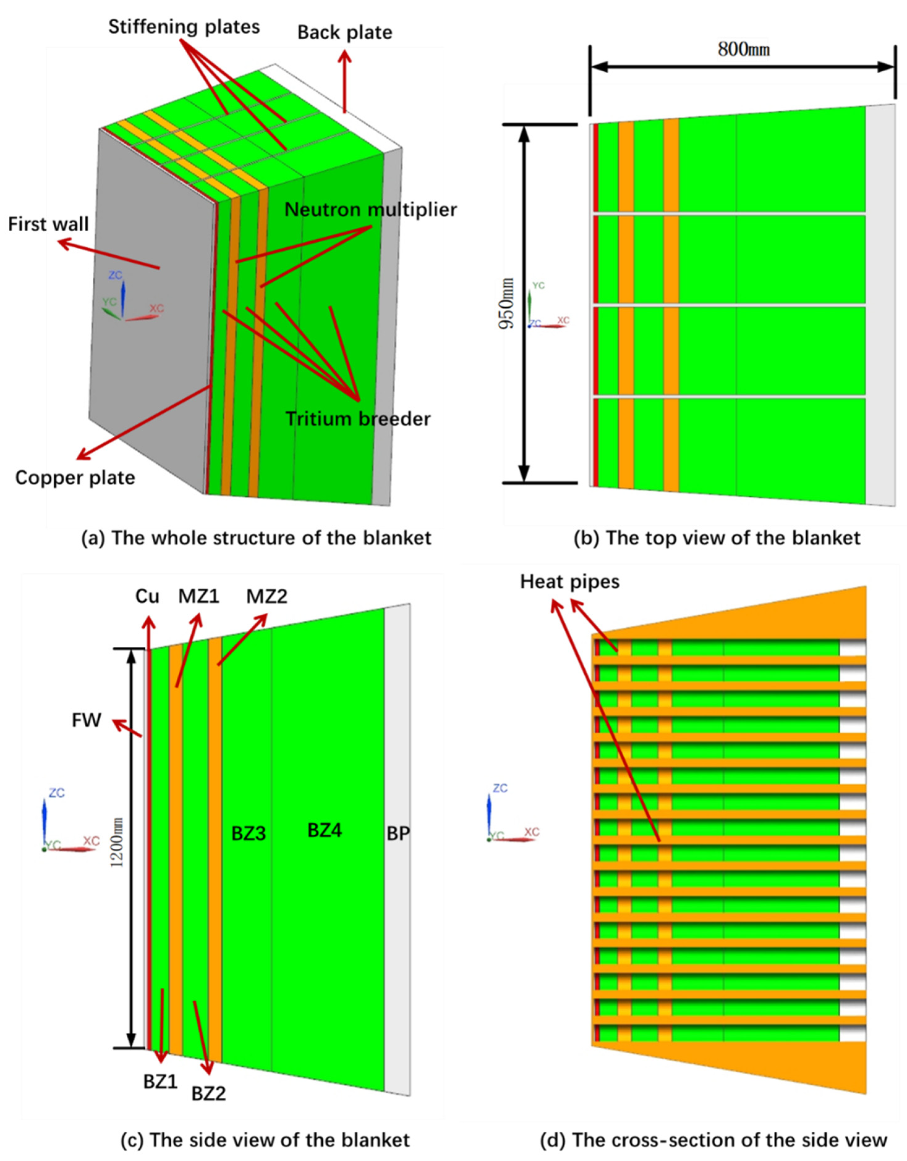
Figure 1 shows the primary structure of the blanket. The geometry size and heat power distribution of WCCB are adopted in this new blanket. At the XC direction, the blanket consists of 9 layers. The first layer is the first wall (FW) that bears the heat flux of plasma. The second layer is the copper plate (Cu), which serves as a heat-conducting fin to improve heat transfer performance. The last layer is the back plate (BP). The rest of the layers are tritium breeder zones (BZs) and neutron multiplier zones (MZs). At the YC direction, the blanket is divided into four parts by three stiffing plates. The main function of the stiffing plates is to improve the overall structural strength of the blanket. At the same time, there are flow channels inside the stiffing plates for transporting the tritium generated.
The materials of the blanket refer to WCCB [
3]. The main materials and their temperature limits are shown in
Table 1. The components of the tritium breeder are 14.4% Li
2TiO
3, 65.6% Be
12Ti and 20% He 80%
6Li enrichment, of which the temperature limit is 1173.15 K. The components of the neutron multiplier are 80% Be and 20% He, of which the temperature limit is 873.15 K. Additionally, the structural materials are of the first wall, stiffing plates, and back plate. The component of the structural materials is 100% RAFM steel, of which the temperature limit is 773.15 K. Meanwhile, there is a thin layer of tungsten armor on the first wall for protection. In Jiang’s paper [
3], the results show that tungsten armor has little influence on the temperature distribution of the blanket due to its high thermal conductivity and relatively thin shape. Thus, the tungsten layer is omitted in this study for simplification.
The inlet and outlet temperature of WCCB are 285 °C and 325 °C, respectively [
3]. The working temperature of the Dowtherm A gravity-assisted heat pipe is between 200 and 400 °C [
8], which is very suitable for this blanket. Therefore, the Dowtherm A gravity-assisted heat pipe is adopted in this study. There are many limitations to heat transport in a heat pipe. Among them, the entrainment limit is an important limit in gravity-assisted heat pipes. For simplicity, only the entrainment limit is calculated for the primary design. The entrainment limit is evaluated by Equations (1)–(4). These equations are given by the work of Hua et al. [
9].
The total power of the blanket is 1.1 MW. After several iterations, the parameters of the heat pipe are finally determined, as shown in
Table 2. The diameter of the heat pipes is 50 mm; the length of the evaporator section is 790 mm. The entrainment limit (
) is 7726 W. There are 12 rows and 16 columns of heat pipes inserted into the blanket. The number of heat pipes is 192. The total limitation of heat transport to heat pipes (1.48 MW) is much bigger than the power of the blanket.
Numerical simulation of the blanket was conducted. The heat flux of the fist wall and heat power of the tritium breeder, neutron multiplier and steel structures are the same as in Jiang’s paper [
3]. The boundary conditions are shown in
Table 3. The heat flux of the plasma on the first wall is 0.454 MW/m
2 [
3]. As the two-phase heat transfer in heat pipes is very complicated and its numerical simulation is still under development, the numerical simulation of the heat pipe was simplified using the following indications. Because of the good isothermal performance of heat pipes, the fixed temperature boundary condition may be more suitable for heat pipe walls in initial designs. Hence, the temperature of 573.15 K was used as the boundary condition of heat-pipe walls according to the parameters of the Pressurized Water Reactor. The other walls were all in adiabatic conditions.
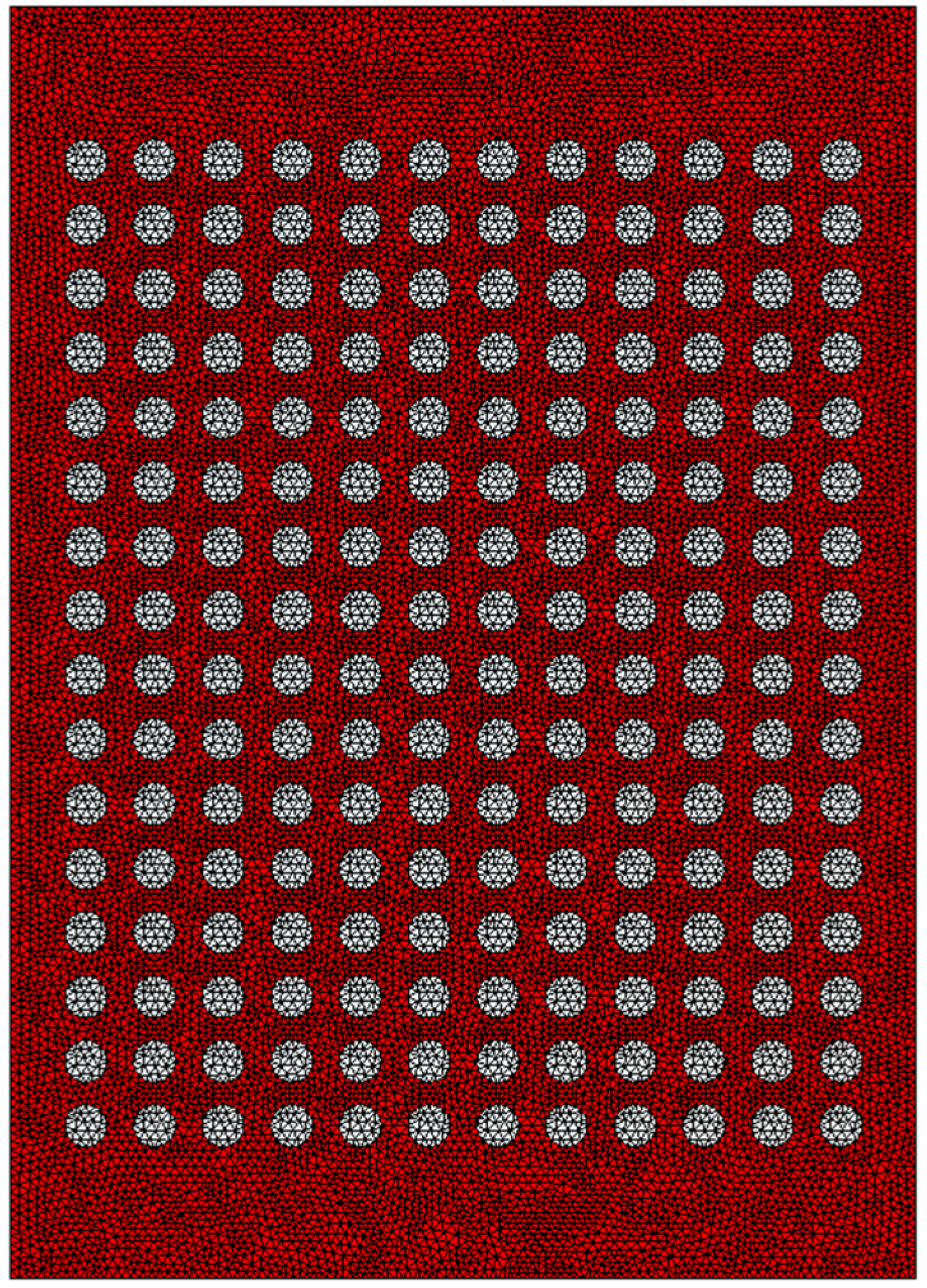
Since the heat pipe is simplified to constant temperature boundary conditions, there are only solid domains in this study. The governing equation is the energy equation. The meshing model is shown in
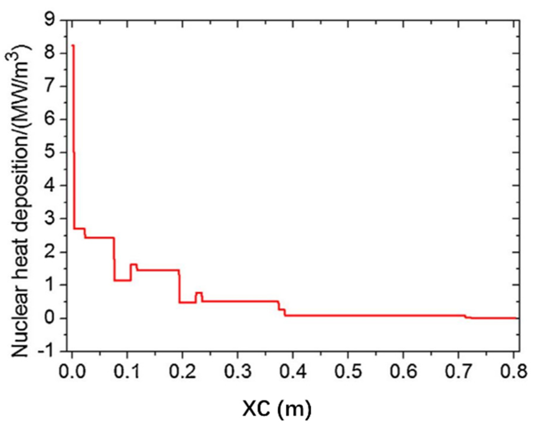
Figure 2. A uniform unstructured tetrahedral mesh was used and the cells’ number is 7047376. ANSYS Fluent conducted the calculation. Moreover, the blanket has an internal heat source. The nuclear heat distribution of the blanket is shown in
Figure 3 [
3]. The thermal conductivities are shown in Equations (5)–(8).
3. Results
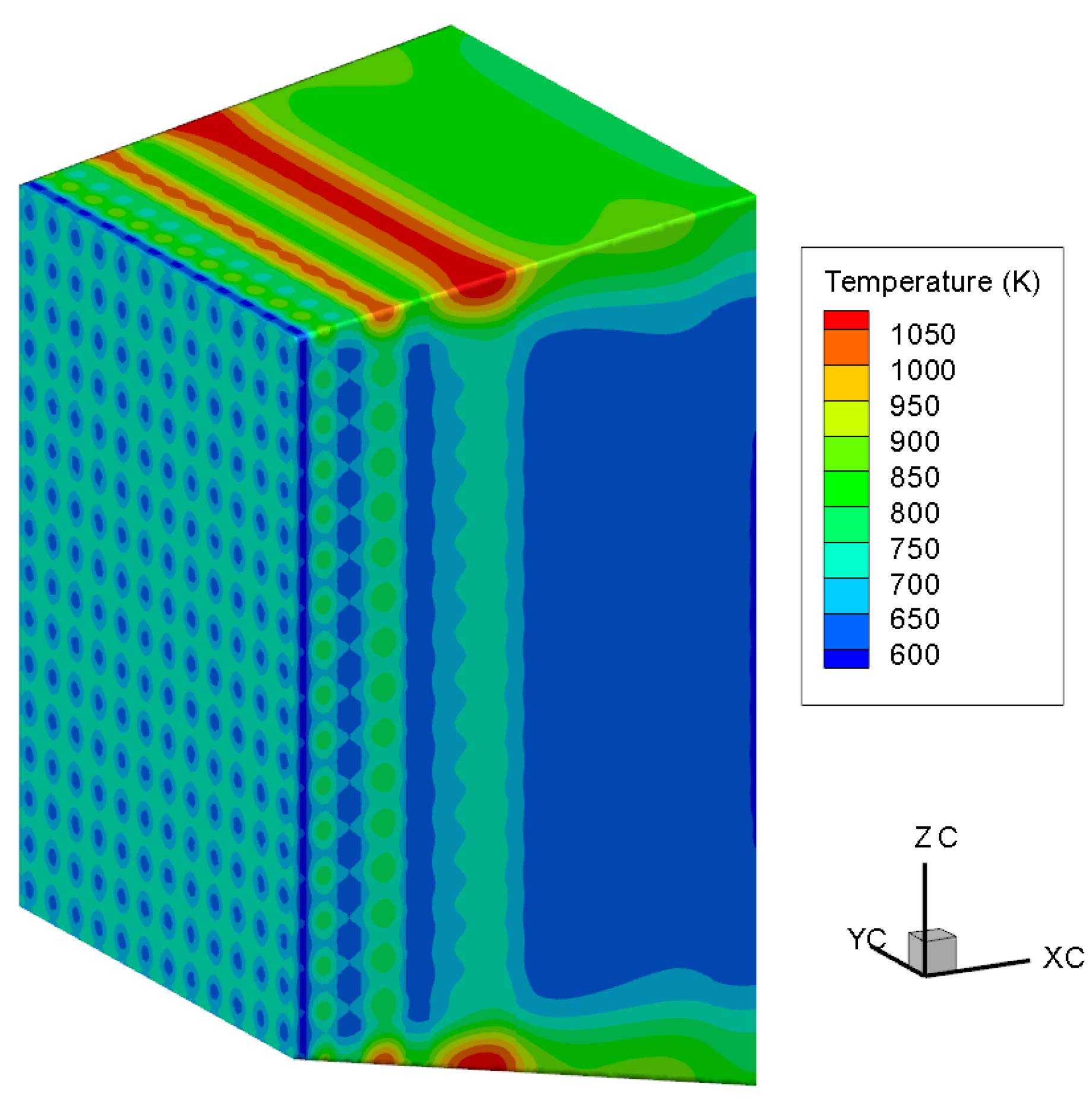
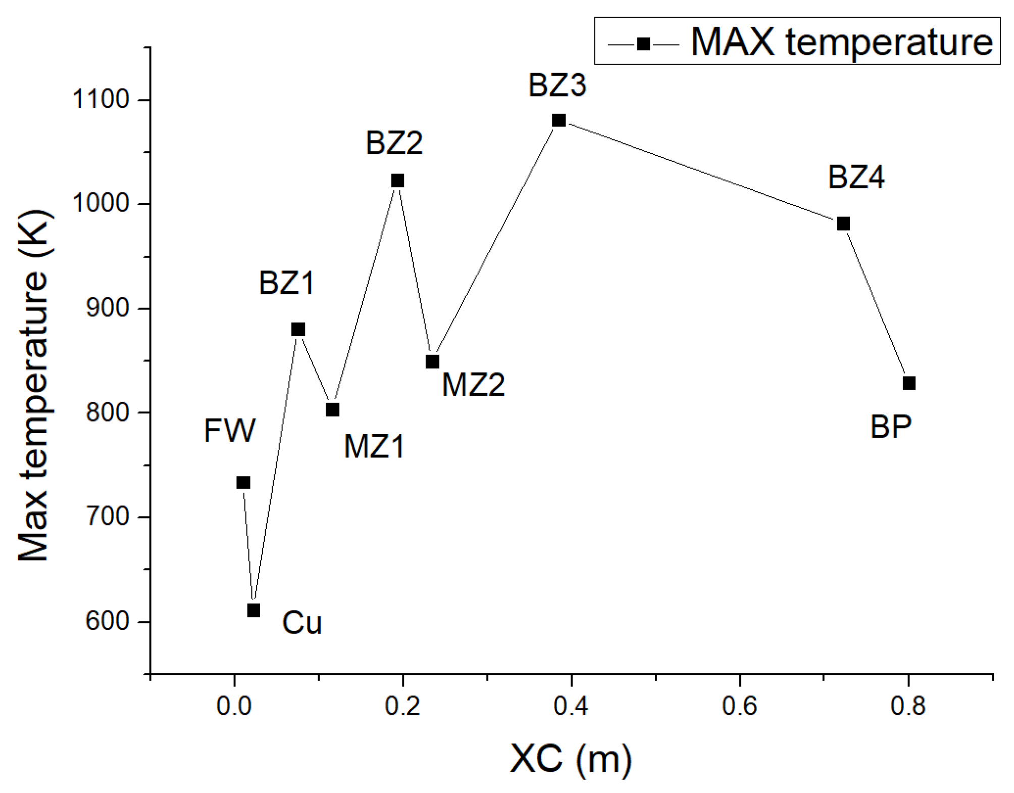
Figure 4 shows the temperature contour of the whole blanket. Although the heat flux of the plasma is very large, the temperature of the first wall is not high because of the high thermal conductivity copper plate. In contrast, the temperatures of the tritium breeder zones are higher. As for the rest, the temperature was higher in the tritium breeder zone with lower thermal conductivity, and lower in the steel structure zone with higher thermal conductivity.
Figure 5 shows the maximum temperature of the nine zones. The maximum temperatures of BZs and MZs are 1081.3 K and 849.8 K, respectively, and all of them are lower than the temperature limits (
Table 1). However, the maximum temperature of the BP is 829.3 K, which is higher than the limit of RAFM steel.
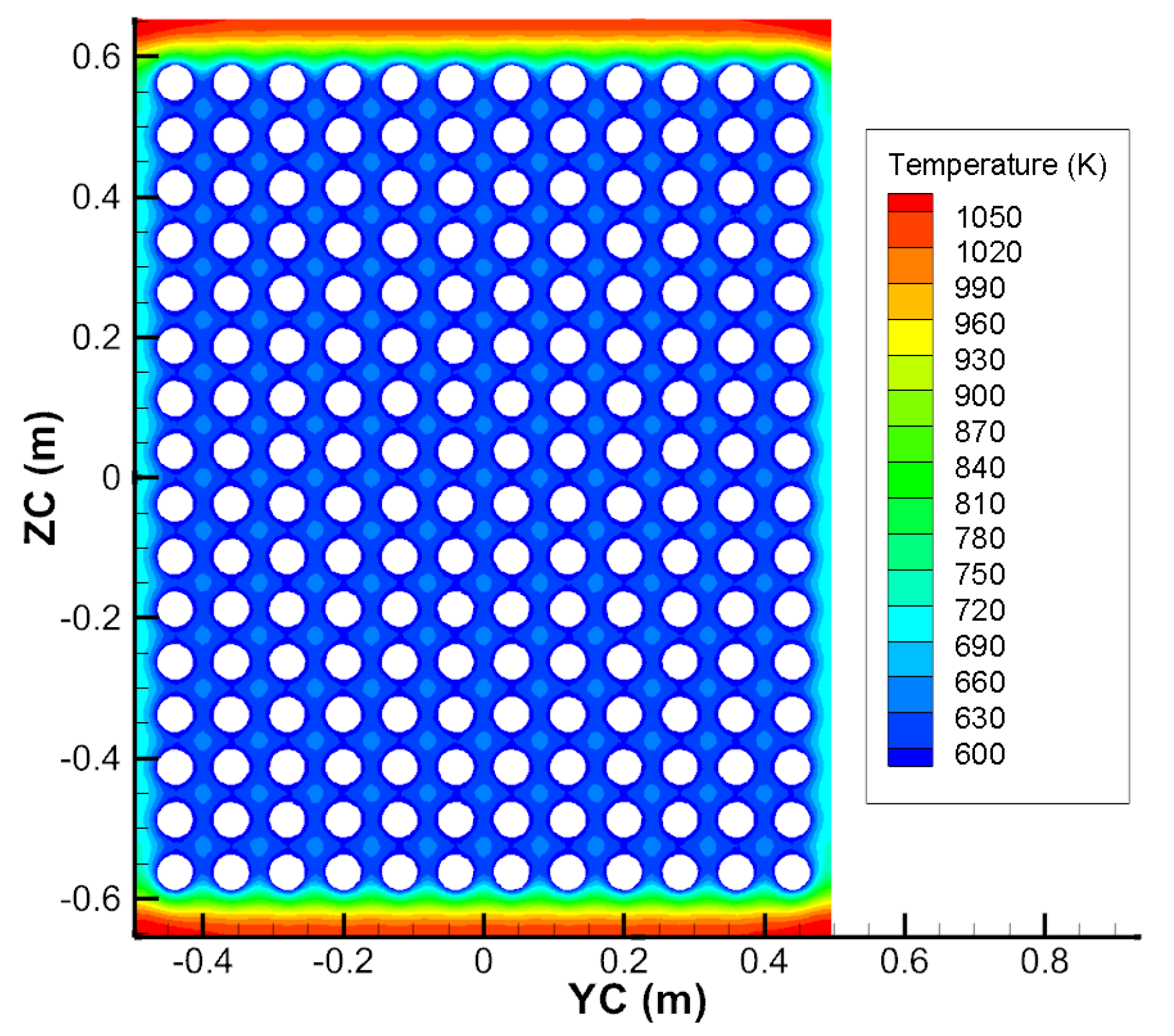
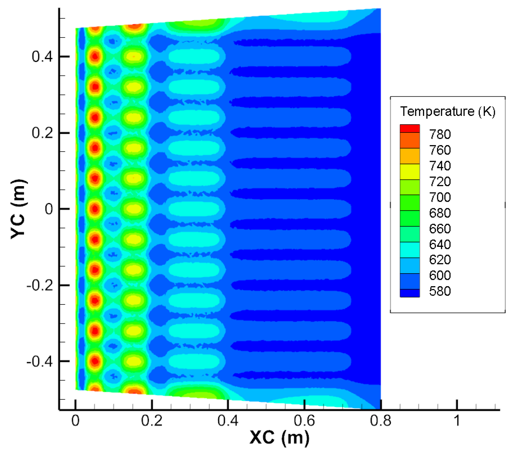
Figure 6 shows the temperature contour of the center plan of the BZ3. The boundary temperature of the ZC direction is highest. The temperature of other areas is very even.
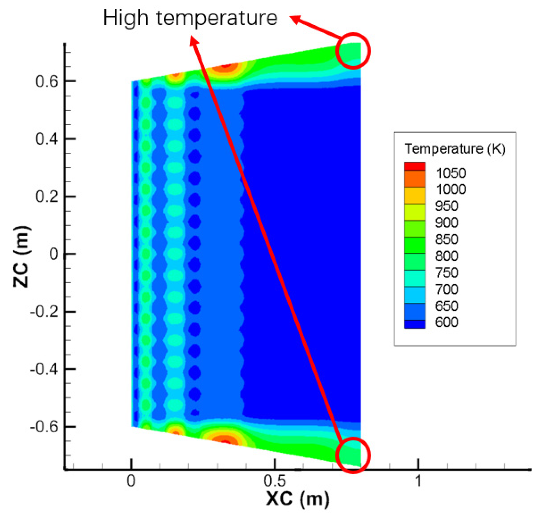
Figure 7 shows the temperature contour of the XC–ZC cross-section of the blanket center. Similarly, the temperature is even, except for the ZC-direction boundary. The slanted upper and lower plates cause these conditions. As the heat pipes are arranged horizontally, insufficient heat transfer occurs at the boundaries.
Figure 8 shows the temperature contour of the XC–YC cross-section of the blanket center. Because the inclination is smaller, the temperature is more even.
4. Optimization
The results show that the temperature of the rear edge of the blanket exceeds the limit. Two columns of the heat pipe are added in these areas to generate better temperature distribution.
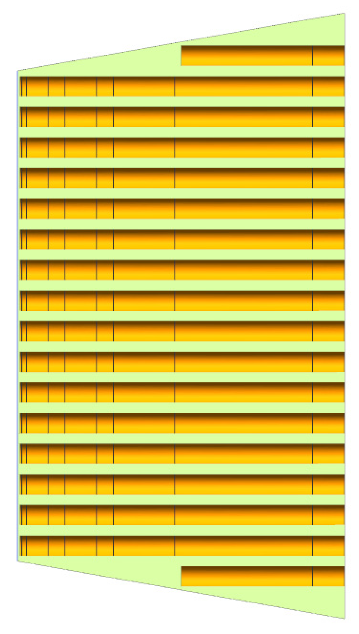
Figure 9 shows the optimized model of the blanket. A line of heat pipes of half-length was added at the top and at the bottom. The parameters of the half-length heat pipes are the same as the other heat pipes.
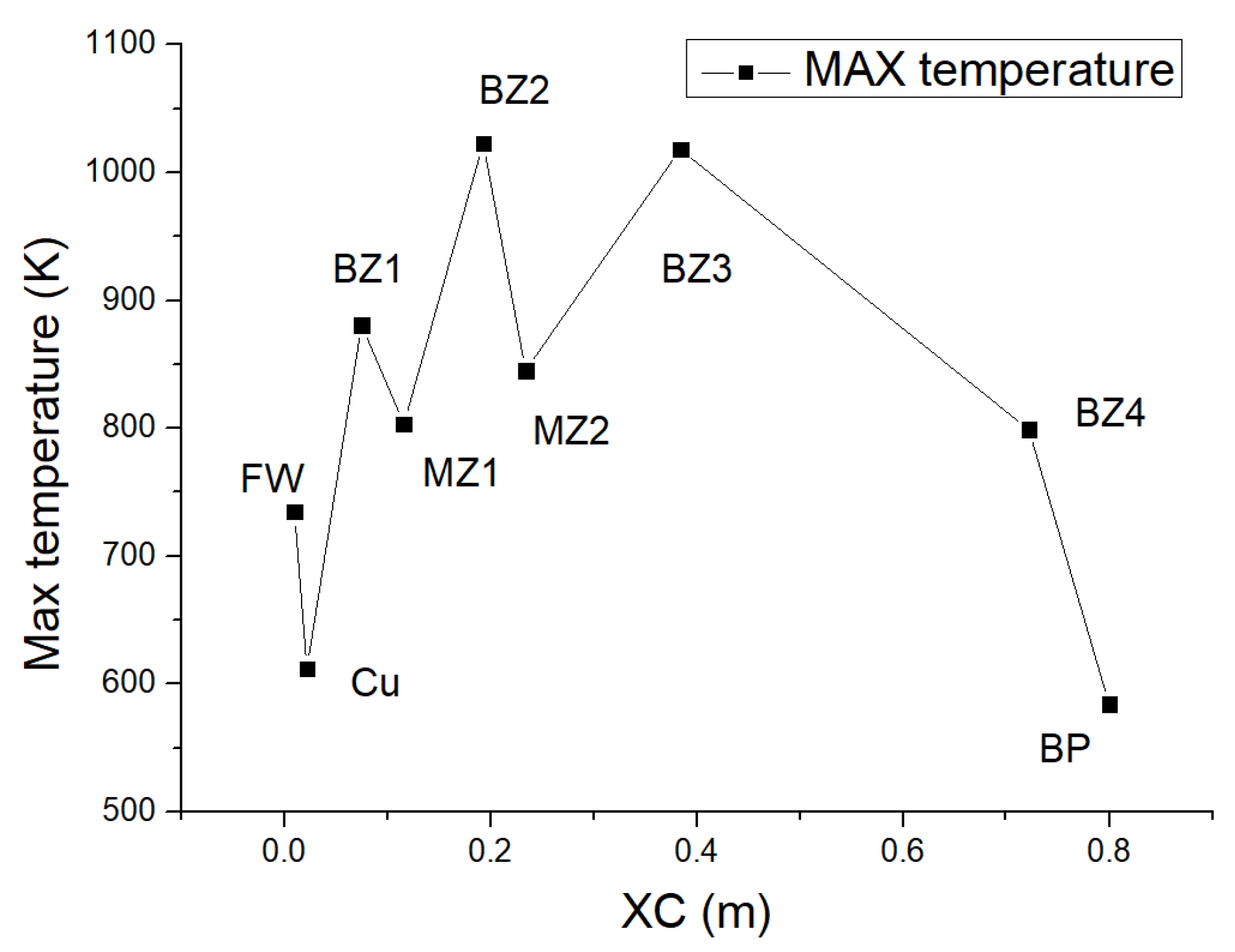
The maximum temperature distribution of the optimized blanket design is shown in
Figure 10. The maximum temperature of BP is 584.0 K, which is much lower than the limit (773.15). In addition, none of the zones’ maximum temperatures exceed the limit.
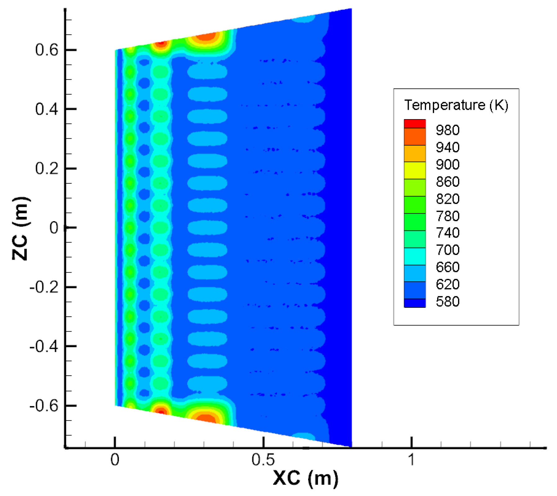
Figure 11 shows the temperature contour of the XC–ZC cross-section of the optimized blanket center. Compared with
Figure 7, the high temperature zones have disappeared.
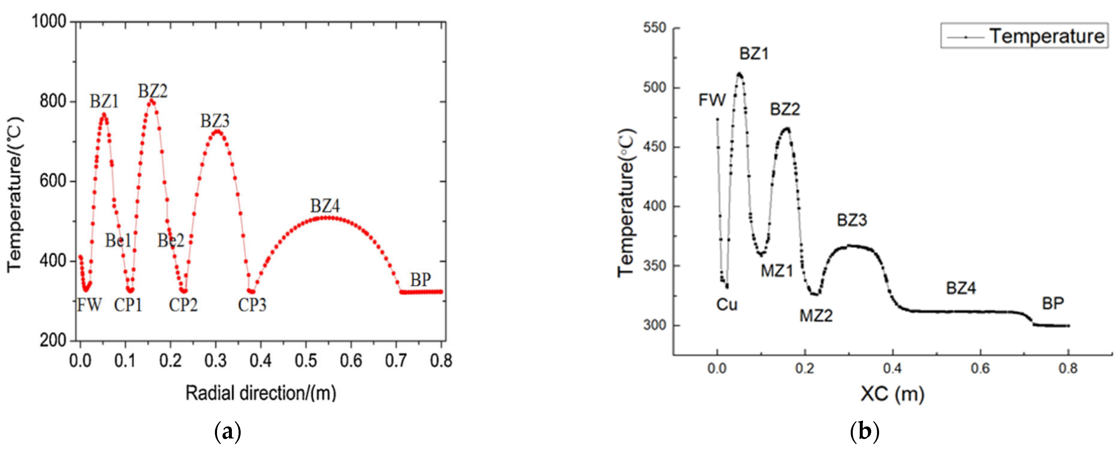
Figure 12 shows the comparison of temperature distribution along the XC direction between the WCCB and heat pipe-cooled blanket. Compared with the CFD results of Jiang et al. [
3], the temperature distribution of the heat pipe-cooled blanket is more uniform. This is a preliminary indication that the heat pipe-cooled blanket is feasible.
5. Conclusions
In this study, a hypothetical heat pipe-cooled blanket for the China Fusion Engineering Test Reactor (CFETR) was proposed and one module of the blanket was analyzed by numerical simulation. The preliminary results show that the temperature distribution of the heat pipe-cooled blanket is more uniform than WCCB. Meanwhile, in-vessel and in-box LOCA and LOFA accidents will be avoided because of the heat transfer mechanism. Compared with WCCB, the heat pipe-cooled blanket may be simpler and more reliable. This study provides a fresh idea for the future design of commercial fusion reactor. However, the two-phase flow in heat pipes was not considered in this study. In fact, the temperature of the heat pipe wall is not constant. Additionally, the effect of neutrons leading to a build-up of gases inside the heat pipes must be considered. More detailed research of heat pipes should be conducted in the future.
Finally, the use of nanofluids to enhance heat transfer in fusion devices has been studied in recent years [
10,
11,
12]. It is necessary to compare the cooling capacity between the nanofluid and the heat pipe. Then, the efficiency, cost and fabrication issues of various cooling methods should be analyzed comprehensively to select the best blanket cooling method.


