Article

Analysis of the Transformer Characteristics for an Integration System with a Wireless Power Transfer Device and Linear Motor

1
Department of Electric Engineering, Changwon University, Changwon 51140, Korea
2
VAM Inc., Changwon 51542, Korea
3
Department of Mechatronics Engineering, Kyungsung University, Busan 48434, Korea
*
Author to whom correspondence should be addressed.
Energies 2021, 14(20), 6769; https://doi.org/10.3390/en14206769
Submission received: 14 May 2021 / Revised: 14 September 2021 / Accepted: 25 September 2021 / Published: 17 October 2021
(This article belongs to the Topic Power System Modeling and Control)

Abstract

:
This paper proposed the transformer characteristic analysis method for the wireless power transfer (WPT) device and linear motor (LM) integration system that can be applied to industrial cleanroom transfer systems. A cable is required to supply the power in conventional systems. In comparison, the proposed system utilizes a WPT device that can simplify power transfers and make a better space utilization. The shape of the wireless power transmission system is proposed along with the discussion of the 2D FEA analysis method about the inductance analyzing method, which are important parameters in magnetic coupling. In addition, ferrite iron loss was calculated based on the analysis results, and applied to the entire modeling circuit to verify the validity of the measured and analyzed values. Finally, the proposed analysis method for the transformer coupling characteristics of the wireless power transfer combined with the transfer system is verified by experiments and simulations.

1. Introduction

A model of the wireless power transfer device that is integrated with a linear motor system is proposed in this paper. Figure 1a shows the conventional system that generally operates the industry robot on a bogie with a power cable and a rotating motor. Generally, a cable is required for this system to supply a power source to the moving bogie [1,2]. The transfer system with a rotating motor consists of mechanical components, such as a speed reducer, belt, chain, and ball screw, which are required to convert rotational motions into linear motions. The vibration from these components causes dusts, and in turn, maintenance is inevitable, especially in a semiconductor factory that requires a clean environment to prevent product defectives [3,4]. Figure 1b shows the proposed system in this paper. The proposed system is integrated with a wireless power transfer (WPT) device and the linear motor (LM) [4]. The power is supplied to the moving part through the WPT, which has no moving parts. The fixing part of the integration system with wireless power transfer device and linear motor is designed according to the dimensions of the company DMT’s linear motor [5]. The principle of a transformer with an air gap is employed for the WPT device. The winding inductance is an important design component for the magnetic energy conversion. The inductance characteristics of the proposed system are analyzed by 2D FEA (Finite Element Analysis). Litz wires are used because the WPT device is operated at a high frequency of 10 kHz, since Litz wires are advantageous at high frequencies due to lower skin effects and conduction losses [6].
The proposed system is composed of ferrite cores for a high-frequency transformer with an air gap and laminated silicon cores to secure the function of a linear motor.
Although ferrite cores have a weaker structural strength, they have a lower core loss than silicon cores. The resonant circuit between inductance and capacitor in the primary circuit is applied to supply the secondary voltage in the WPT [7]. The measured inductance value is applied to circuit simulation to increase the accuracy of the analysis. Circuit simulation analysis was carried out in MATLAB by applying the CLLC circuit [8,9,10,11].
A prototype is fabricated to prove the performance of the proposed model. The inductance of the iron core and winding is measured and compared with the analysis value by 2D FEA. It was applied to the modeling circuit, and we verified the performance for wireless power transmission.

2. Configuration of System

2.1. Integration System of a Wireless Power Transfer Device and Linear Motor

The various concepts for wireless power transfer systems are used for transportation, EV, mobile phone, note-book, etc. and the moving parts of these systems are configured to get power from the fixed part of these systems [12].
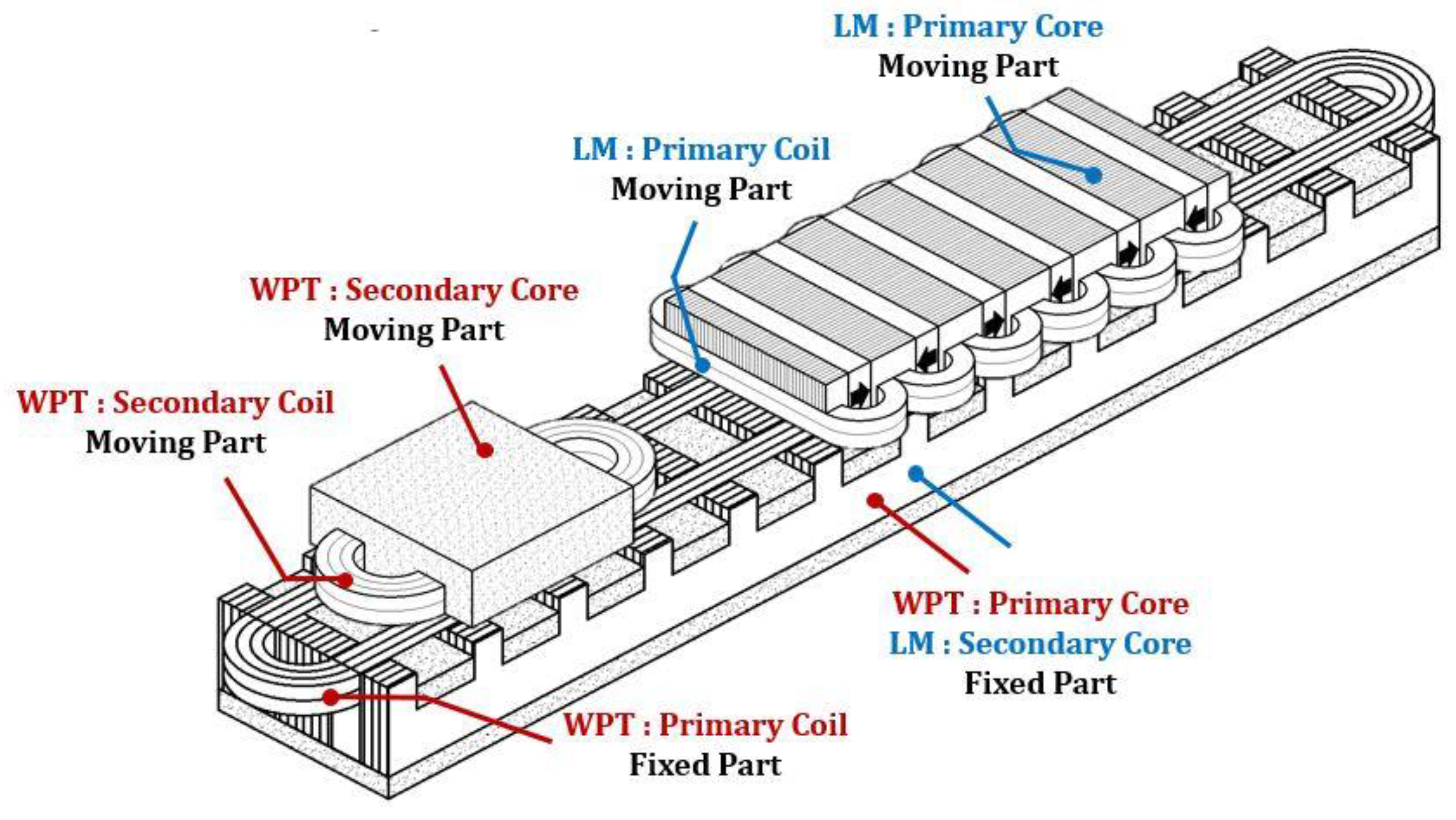
Figure 2 shows the integrated system of the proposed WPT device with the LM. The proposed system has a better space utilization because the fixed part serves a dual purpose, namely the primary of the WPT and the secondary of LM. The moving part that is installed under the robot base plate is composed of the secondary part of the WPT and the primary part of LM. The linear motor generates the thrust between the teeth of the secondary core and the teeth of the primary core in Figure 2, and the principles are the same of conventional flux switching and flux reversal linear motors [3].
The LM operates by receiving power from the WPT. A concept diagram for this is shown in Figure 3. Figure 3 shows the conceptual diagram of a power system for the proposed system. Figure 3 shows the transformer principle with an air gap is applied to transfer the power from the WPT primary (fixed part) to the WPT secondary (moving part). The transferred AC power is converted to DC power, for the primary LM and robot [13].

2.2. Wireless Power Transfer Device

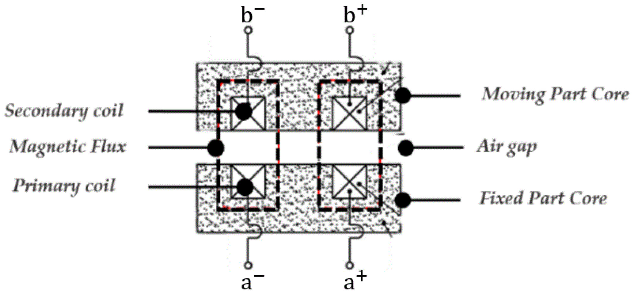
Figure 4 shows the topology of the WPT device. Compared to a conventional transformer, the proposed WPT has a 1 mm air gap between the primary(fixed part core) and secondary(moving part core) core is shown Figure 4. The power is transferred by magnetic energy, not electrical energy. The E-core is utilized, and the shell-type winding construction method is used. The resonant circuit topology, as shown in Figure 5, is employed to utilize the large leakage inductance in the primary winding due to the long length to create the resonant tank with the resonant capacitor. The topology also employs the semiconductor elements (Q1–Q4) with a 10 kHz switching frequency.

3. Specification of the Wireless Power Transfer

3.1. Specification of the Transfer and Receiver

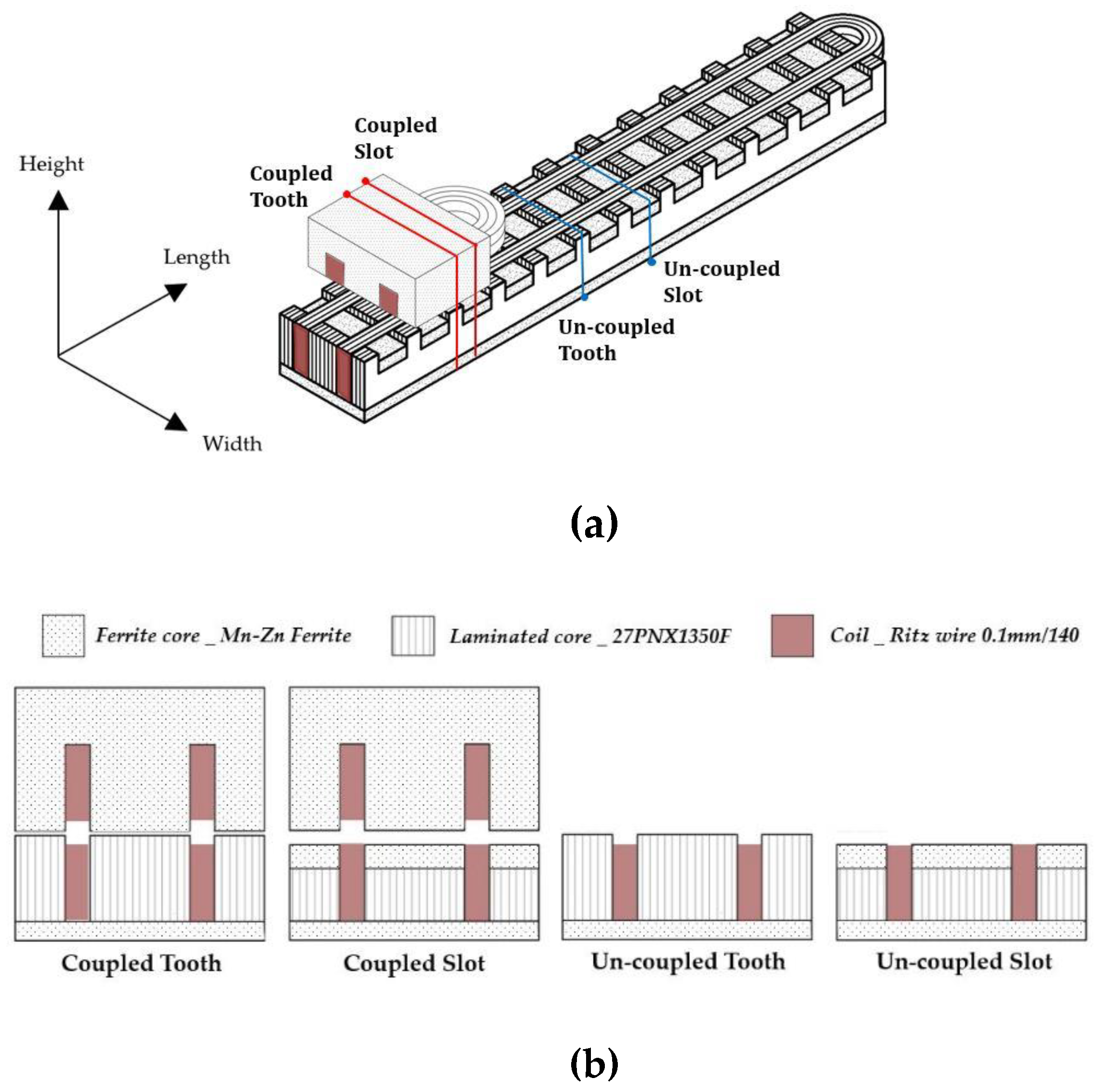
The fixed part of the WPT device is designed by modifying a commercial LM, as shown in Figure 6a [1,2]. The length and width of the fixed part are 1080 mm and 50 mm, respectively. The length and width of the moving part are 108 mm and 50 mm, respectively. The detailed dimensions of the WPT are shown in Table 1. Figure 6b shows the cross section of the WPT device. The WPT device can be divided into four parts, i.e., the coupled tooth, coupled slot, uncoupled tooth, and uncoupled slot part. The dimensions and configurations of each part are different, with a ferrite core, laminated silicon core, and Litz wire. A ferrite core is inserted at the bottom of the tooth and slot of the WPT, which is to further secure the flow of the magnetic flux [8]. The proposed system needs laminated cores to secure the functionality of the linear motor. Therefore, considering the function from the point of view of a wireless power transmission device, a ferrite core is inserted in the slot part of the tooth section of the linear motor’s fixed part.
The dimensions and specifications of the wireless power transfer device are listed in Table 1.
V p = 4.44 f × N × ϕ = 4.44 f × N × B × S
In the above Equation (1), when the transformer primary voltage e is 100 Vrms, the magnetic flux is = 0.00010725 Wb, and the magnetic path area S is 0.00216 m2, so the magnetic flux density is B = 0.0496 T.

3.2. Specification of the Winding Coil

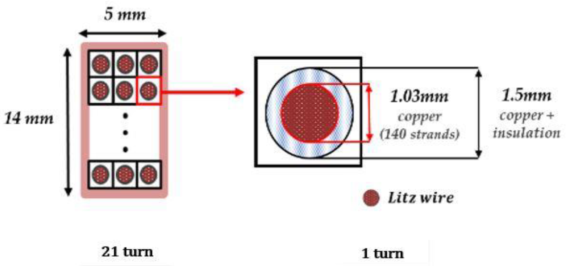
When the frequency is increased, the current flow region is decreased in the wire due to the skin effect, which causes a higher resistance and reduces the efficiency. As mentioned earlier, the WPT device is operated at a high frequency. Thus, Litz wires are employed to reduce the skin effect and losses instead of using general solid and strand wire. Figure 7 shows the configuration of the coil and coil area. The selected Litz wire has 140 strands for one turn.

4. Design and FEA Analysis

Because the number of coupled, uncoupled teeth and coupled, uncoupled slots according to the position of the secondary moving part is the same, the simple 2D FEA is employed to analyze the electromagnetic characteristics. Figure 8 shows the WPT device parameter does not change according to the position of the secondary moving part, because the secondary moving part with 108 mm length at any position always keeps the six coupled teeth and the six coupled slots.

4.1. Inductance of Primary and Secondary

The total inductance of primary part L 1 is defined as follows:
L 1 = 6 × ( L p c t + L p c s ) + 54 × ( L p u n c t + L p u n c s )
L p c t : inductance of a coupled tooth.
L p c s : inductance of a coupled slot.
L pun c t : inductance of an uncoupled tooth.
L pun c s : inductance of an uncoupled slot.
L p c t m : magnetization inductance of a coupled tooth.
L p c s m : magnetization inductance of a coupled slot.
L p c t l k : leakage inductance of a coupled tooth.
L p c s l k : leakage inductance of a coupled slot.
L pun c t l k : leakage inductance of an uncoupled tooth.
L pun c s l k : leakage inductance of an uncoupled slot core.
L pct , L pc s , L p u n c t , and L p u n c s are the total inductance for each divided part, as shown in Figure 6b. The length of the tooth and slot are 6.5 mm and 11.5 mm, respectively, for the moving direction. The total length of the primary and secondary core is 1080 mm and 108 mm, respectively. Therefore, the coupled tooth and slot can be divided into 6 pieces each. The same method as for the coupled part, the uncoupled tooth and the slot parts are can be divided into 54 pieces each. Since L 1 c t and L 1 c s are coupled parts between primary and secondary parts, these are divided into magnetization and leakage inductance as follows:
L p c t = L p c t m + L p c t l k
L p c s = L p c s m + L p c s l k
L p u n c t = L p u n c t l k
L p u n c s = L p u n c s l k
From the above Equations (2)–(6), the total inductance of the primary part can be redefined as follows:
L p = L p m + L p l k
L p m = L p c t m + L p c s m
L p l = L p c t l k + L p c s l k + L p u n c t l k + L p u n c s l k
Similar to the definition of the inductance of the primary part in Equations (2)–(9), the inductance of the secondary part can also be defined as follows:
L s = 6 × ( L s c t + L s c s )
L s c t : inductance of a coupled tooth core.
L s c s : inductance of a coupled slot core.
L s c t m : magnetization inductance of a coupled tooth core.
L s c s m : magnetization inductance of a coupled slot core.
L s c t l k : leakage inductance of a coupled slot core.
L s c s l k : leakage inductance of a coupled slot core.
L s c t = L s c t m + L s c t l k
L s c s = L s c s m + L s c s l k
From the above Equations (10)–(12), the total inductance of the secondary part can be redefined as follows:
L s = L s m + L s l k
L s m = L s c t m + L s c s m
Table 2 shows the calculated inductance by 2D FEA simulation. The total leakage inductance of primary part L p l k is much higher than the total mutual inductance of primary part L p m since the uncoupled part occupies the most of them in the WPT device.
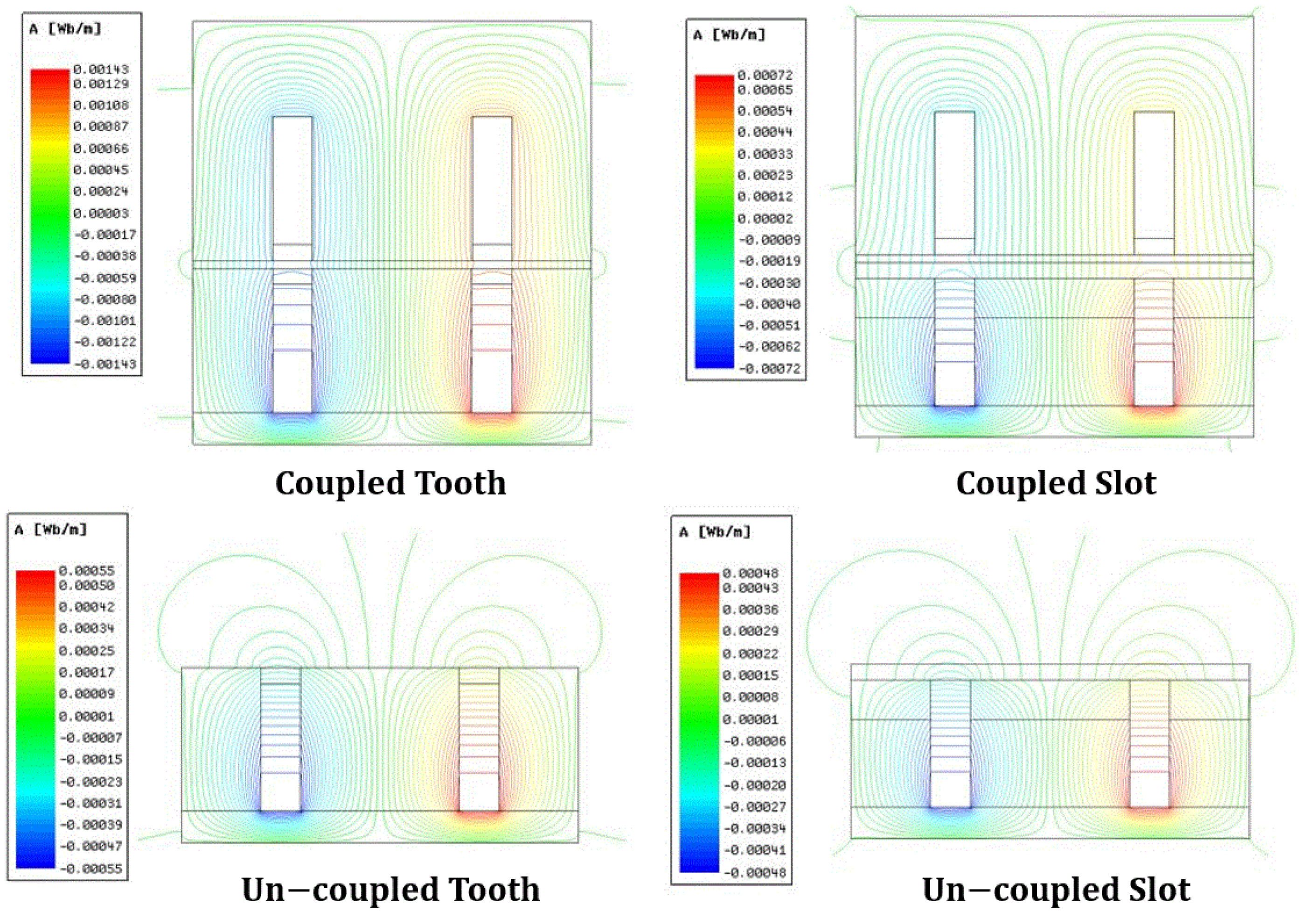
Figure 9 shows the shape of the magnetic flux distribution for the coupled tooth, coupled slot, uncoupled tooth, and uncoupled slot part in Figure 6. For the coupled tooth and slot, the magnetic flux flows almost through the core.

4.2. Calculation of Coreloss

The calculated laminated and ferrite core losses are shown in Table 3 and Table 4, respectively. Table 3 below is the iron loss value in case of magnetizing current 3.91 A at no load, and Table 4 is the iron loss caused by magnetizing current 3.91 A and load current 4.73 A in the uncoupled model under load. Unlike general transformers that only generate iron loss due to magnetizing current even under load, the transformer of the proposed WPT device suffers from iron losses due to the sum of the magnetizing current and load current in the uncoupled parts under load. The reason why there is a difference in loss with and without load is that the primary fixing part in the proposed device has a longer structure than the secondary moving part.

4.3. Calculation of the Resonance Capacitor

We proposed in this paper a model of an integration system with a wireless power transfer device and linear motor, which adopted a transformer with a big air gap and long primary wires. The wireless power transmission device has a large leakage inductance for the primary winding due to the long length of the primary part, a small magnetizing inductance, and a low coupling coefficient. It makes the transmission efficiency very low. The system efficiency is improved by adopting resonant capacitance to compensate leakage inductance in transferring energy to the load. For this method, it is necessary equalize the resonance frequency of the primary side and the secondary side by using a resonance capacitor [7].
C = 1 ( 2 π f ) 2 L l k  

5. Experiment

5.1. Inductance Measurement

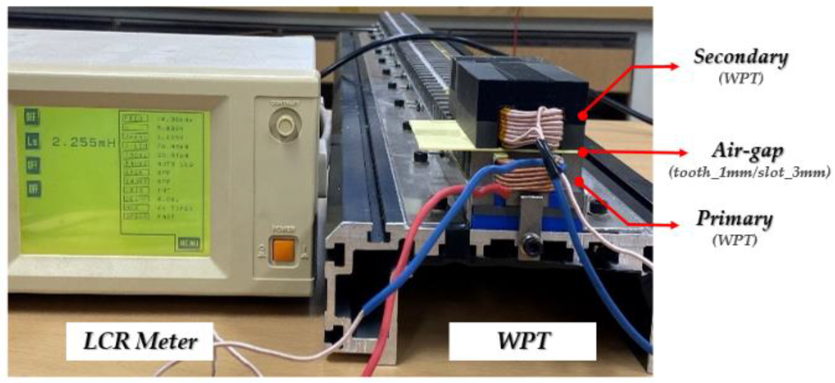
In Figure 10, the primary and secondary of the WPT device have a 1 mm air gap for the inductance experiment.
Table 5 shows the simulated inductance and experimental inductance of the wireless power transmission device.
The transformer of the WPT device proposed in this paper has the characters of leakage inductance along the long primary side wire with an air gap and uncoupled part. In addition, it has a low coupling coefficient, and the inductance characteristics for this can be seen in Table 5 above.
In Table 5, the simulation and test values do not have a large error, so it can be seen that the design and analysis are verified. However, there is an error of 20% between the L1 leakage simulation and the experimental value, which is due to the existence of a gap between the ferrite core and the laminated core combination in the device manufacturing.
In Table 6, each resonant capacitor is calculated as 0.109 μF and 1.217 μF by Equation (15). Additionally, in the measured data in Table 6 is shown the resistance measurement values are 0.95 Ω and 0.11 Ω.

5.2. Resonant Circuit

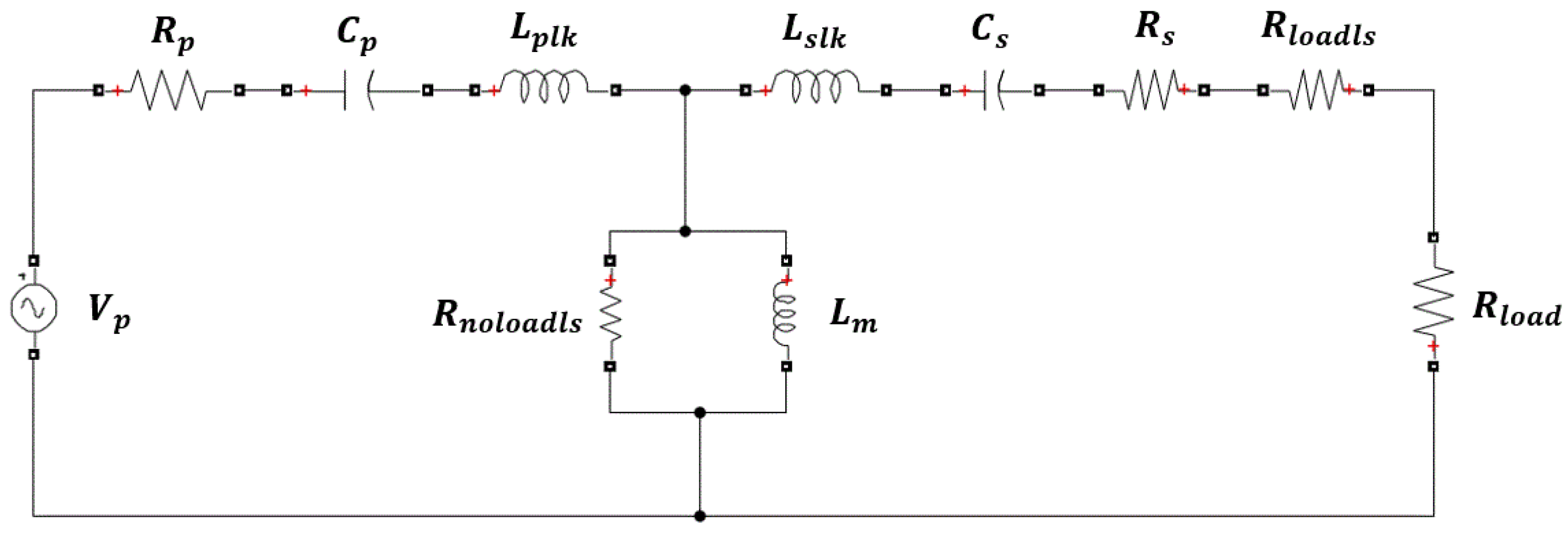
The constant of the above equivalent circuit is the value by reflecting the measured inductance, resistance, and 2D finite element simulation iron loss data. As shown in Figure 11, this paper adopts a series-series system in which the resonance capacitor and the coil are connected in series because a regeneration can be easily performed from the symmetry of the circuit in this system [7].
The result is total current I p 5.745 A, load current I s 3.561 A, magnetizing current I m 4.182 A, iron loss current I C 0.549 A output P s 272.72 W, input P p 436.64 W, iron loss Pc and ferrite loss PFe 180.111 W, iron loss R n o l o a d l s 186.15 Ω, and iron loss R l o a d l s 5.856 Ω. The primary resonant capacitor C p values are 0.109 μF.
Rnoloadls considers the iron loss caused by the magnetizing current in case of no load. In the case of load, the Rloadls additionally considers the iron loss caused by the load current. In this case, considering the additional iron loss of 131 W generated during the load, the secondary additional iron loss resistance constitutes 5.856 Ω.
In the above simulation, the primary and secondary leakage inductances resonate with the series capacitors C p and C s . Then, the total primary current I p is calculated by calculating the primary excitation current I m in Equations (16) and (17) and the primary load current I p l o a d load, which has a phase difference of 90 degrees:
I m = V p j ω L m
I p = ( I p φ ) 2 + I p l o a d 2
In the above equation, since the magnetizing current I m is 3.925 A and the primary load current I s is 3.693 A, the primary current I p is 5.745 A. Therefore, according to Equation (18), the loss P R of the coil is 30.20 W as the sum of 28.68 W for the primary coil loss P p R and 1.514 W for the secondary coil loss P s R :
P R = P p R + P s R
η = P s P p
The efficiency of the wireless power transformer is obtained from the result obtained through the MATLAB simulation, as shown in Equation (19). The result is 62.45% efficiency by P p 436 W and P s   272 W.

6. Conclusions

The analysis of the proposed WPT device in the integration system with LM is proposed, and the integration system with a wireless power transfer device and linear motor would be applied to the robot in a clean room to reduce noise and to simplify the system.
The basic design of the transformer of the 500 W class WPT unit is studied along with the magnetic inductance by the equivalent magnetic circuit method, the magnetic and leakage inductance of the primary and secondary windings by the two-dimensional finite element method, the resonance capacitor, the resistance of the winding, and the efficiency. In particular, in the case of primary and secondary winding magnetic and leakage inductance, each region was divided into six parts and analyzed through a two-dimensional finite element method to obtain accurate values.
The inductance values obtained through the analysis were compared with the results of actual experimental measurements. The difference between simulation and experiment results is approximately 19.1%–1%, which is within the acceptable range, which may be caused by manufacturing processes such as the existence of a gap between the ferrite core and the laminated core.
In the future, the power transfer will be verified by composing and testing the transformer and convert device of the WPT part, and the integration system with wireless power transfer (WPT) device and linear motor (LM) will be completed by combining the linear motor part [14].

Author Contributions

Conceptualization, D.K.; manufacturing, D.K.; software, H.W. and C.J.; validation; H.A.; writing—original draft preparation, H.W.; writing—review and editing, J.-H.P.; visualization, H.W.; supervision, T.K. All authors have read and agreed to the published version of the manuscript.

Funding

This results was supported by “Regional Innovation Strategy (RIS)” through the National Re-search Foundation of Korea (NRF) funded by the Ministry of Education (MOE) and Industry-Academic Cooperation Based Platform R&D funded Korea Ministry of SMEs and Startups in 2021. (Project No. S3025558).

Institutional Review Board Statement

Not applicable.

Informed Consent Statement

Not applicable.

Data Availability Statement

Not applicable.

Acknowledgments

This research was conducted with VAM, Inc. and CWNU CPEC.

Conflicts of Interest

The authors declare no conflict of interest.

References

  1. Woo, H.-J.; Park, J.-H.; Joo, C.-D.; Ahn, H.-G.; Kang, D.-H.; Kim, T.-K. Design of Wireless Power Transfer in Integration System of Wireless Power Transfer and Linear Motor. In Proceedings of the KIEE EMECS Fall Conference, Jeju, Korea, 29–31 October 2020; pp. 37–39. [Google Scholar]
  2. Kang, D.-H. Linear Transferring System Having Wireless Power Supply. Patent PCT KR2020 017108,10-2020-0094888, 29 July 2020. [Google Scholar]
  3. Lee, J.-Y.; Lee, I.-J.; Kim, J.-W.; Chang, J.-H.; Kang, D.-H.; Chung, S.-U.; Hong, J.-P. Contactless Power Transfer System Combined with Linear Electric Machine. In Proceedings of the 2007 International Conference on Electrical Machines and Systems (ICEMS), Seoul, Korea, 8–11 October 2007; pp. 1544–1548. [Google Scholar]
  4. Kim, J.M.; Kang, D.H.; Jung, S.J.; Bang, D.J. Design of the Transverse Flux Linear Motor with the Integrated Contactless Power Supply. In Proceedings of the 5th Linear Drives for Industry Applications (LDIA), Kobe, Japan, 25–28 September 2005; pp. 286–289. [Google Scholar]
  5. Dynamic Motion Technology CO. LTD. Available online: http://www.dmtec.net/en/product/linear-motors (accessed on 24 September 2021).
  6. Wang, C.-S.; Stielau, O.H.; Covic, G. Design Considerations for a Contactless Electric Vehicle Battery Charger. IEEE Trans. Ind. Electron. 2005, 52, 1308–1314. [Google Scholar] [CrossRef]
  7. Yazaki, Y.; Nishimura, T.; Ohnishi, W.; Imura, T.; Fujimoto, H. Moving Coil Type Wireless Linear Motor Based on Magnetic Resonance Coupling. In Proceedings of the IECON 2017—43rd Annual Conference of the IEEE Industrial Electronics Society, Beijing, China, 29 October–1 November 2017; pp. 7288–7293. [Google Scholar] [CrossRef]
  8. Jin, Y.; Liu, S.; Wu, C.; Li, Y.; Ma, D. Research on Contactless Power Transmission System Based on DCDC Charging Module for Unmanned Underwater Vehicles. In Proceedings of the 2019 IEEE 4th Advanced Information Technology, Electronic and Automation Control Conference (IAEAC), Chengdu, China, 20–22 December 2019; IEEE: Piscataway, NJ, USA; Volume 1, pp. 2019–2023. [Google Scholar] [CrossRef]
  9. Reatti, A.; Musumeci, S.; Corti, F. Frequency Analysis and Comparison of LCCL and CLLC Compensations for Capacitive Wireless Power Transfer. In Proceedings of the 2020 AEIT International Conference of Electrical and Electronic Technologies for Automotive (AEIT AUTOMOTIVE), Turin, Italy, 23–25 September 2020; IEEE: Piscataway, NJ, USA; pp. 1–6. [Google Scholar] [CrossRef]
  10. Kim, E.S.; Goo, D.H.; Kim, J.M.; Kang, D.H.; Shin, B.C.; Kong, Y.S.; Yang, S.C. Contact-Less Power Supply Using Series-Parallel Resonant Converter; The Korean Institute of Power Electronics: Seoul, Korea, 2002; pp. 103–107. [Google Scholar]
  11. Jenson, J.; Therattil, J.P.; Johnson, J.A. A Novel LCC-LCL Compensation WPT System for Better Performance. In Proceedings of the 2019 IEEE International Conference on Electrical, Computer and Communication Technologies (ICECCT), Coimbatore, India, 20–22 February 2019; IEEE: Piscataway, NJ, USA; pp. 1–6. [Google Scholar] [CrossRef]
  12. Andrei, M.; Claudiu, B.; Vadan, I. Wireless Power Transmission—State of the Art and Applications. In Proceedings of the 2019 8th International Conference on Modern Power Systems (MPS), Cluj-Napoca, Romania, 21–23 May 2019; IEEE: Piscataway, NJ, USA; pp. 1–6. [Google Scholar] [CrossRef]
  13. Lee, J.-Y.; Kim, J.-W.; Woo, B.-C.; Kang, D.-H. Characteristic Analysis of a Permanent Magnet Transverse Flux Linear Motor with Spiral Core. J. Magn. 2013, 18, 111–116. [Google Scholar] [CrossRef] [Green Version]
  14. Dong, Y.; Nuchkrua, T.; Shen, T. Asymptotical stability contouring control of dual-arm robot with holonomic constraints: Modified distributed control framework. IET Control. Theory Appl. 2019, 13, 2877–2885. [Google Scholar] [CrossRef]
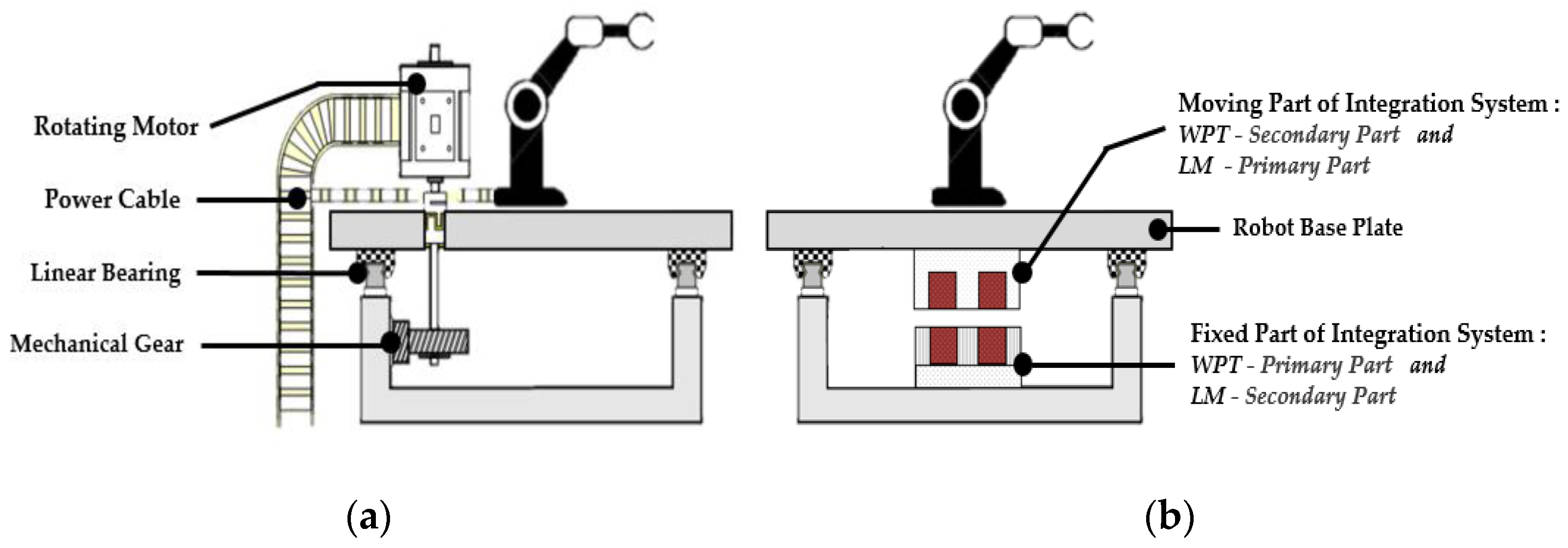
Figure 1. Transfer system. (a) Conventional system. (b) Proposed system.
Energies 14 06769 g001
Figure 2. Geometry of the integration system with WPT and LM.
Energies 14 06769 g002
Figure 3. Concept diagram of the power system.
Energies 14 06769 g003
Figure 4. The topology of the wireless power transfer.
Energies 14 06769 g004
Figure 5. The topology of the wireless power transfer circuit diagram of the power supply.
Energies 14 06769 g005
Figure 6. Configuration of the WPT device: (a) total shape; (b) cross section.
Energies 14 06769 g006
Figure 7. Configuration of the coil and coil area.
Energies 14 06769 g007
Figure 8. Division of inductance calculation sections.
Energies 14 06769 g008
Figure 9. Magnetic flux distribution by primary current.
Energies 14 06769 g009
Figure 10. Experiment setup.
Energies 14 06769 g010
Figure 11. Simulation CLLC circuit.
Energies 14 06769 g011
Table 1. Dimensions and specification of a wireless power transfer device.
DescriptionValue
Primary partlength (mm)1080
Width (mm)50
Height (mm)23
Length of tooth part (mm)6.5
Length of slot part (mm)11.5
Secondary partlength (mm)108
Width (mm)50
Height (mm)30
Air gap (mm)1
Coil area of primary part (mm2)70
Coil area of secondary part (mm2)80
Ferrite coreMn-Zn ferrite
Laminated silicon core27PNF1500
Number of winding turns for each part21
Input voltage (Vrms)100
Frequency (kHz)10
Table 2. The inductance for each part by 2D FEA simulation.
Coupled Tooth
(6 EA)
Coupled Slot
(6 EA)
Uncoupled Tooth
(54 EA)
Uncoupled Slot
(54 EA)
Total
(mH)
L p (mH)0.2980.2410.8921.282.713
L p m (mH)0.2370.152 0.389
L p l k (mH)0.0610.0890.8921.282.323
L s (mH)0.3040.282 0.587
L s m (mH)0.2370.152 0.389
L s l k (mH)0.0670.13 0.198
Table 3. Core losses without load.
Coupled Tooth (6 EA)Coupled Slot (6 EA)Uncoupled Tooth (54 EA)Uncoupled Slot (54 EA)Total Losses (W)
Laminated
silicon core loss (W)
10.5151.53429.7596.50748.316
Ferrite
Core loss (W)
0.2520.0090.1180.3880.77
Total losses (W)10.7671.54429.8786.89549.086
Table 4. Core losses with load.
Coupled Tooth (6 EA)Coupled Slot (6 EA)Uncoupled Tooth (54 EA)Uncoupled Slot (54 EA)Total Losses
(W)
Laminated
silicon core loss (W)
10.5151.534139.44925.99177.488
Ferrite
Core loss (W)
0.2520.0090.5991.8682.728
Total losses (W)10.7671.543140.04827.858180.216
Table 5. Measured inductance.
Simulation (Unit: mH)Experiment (Experiment/Simulation %)
L p (mH)2.7132.274 (83.8%)
L p m (mH)0.3890.393 (101%)
L p l k (mH)2.3231.881 (80.9%)
L s (mH)0.5870.601 (102.3%)
L s m (mH)0.3890.393 (101%)
L s l k (mH)0.1980.208 (105%)
Table 6. Designed and measured value of wireless power transfer device.
Description DesignedMeasured
V p Primary voltage(V)100
I p Primary current(A)5.745
P p Primary power(W)436.64
R p Primary resistance(Ω)10.955
L p l k Primary leakage inductance(mH)2.3231.881
C p Primary resonance capacitor(μF)0.109
L m Magnetizing inductance(mH)0.3890.393
I m Magnetizing current(A)3.925
I S Secondary load current(A)3.693
R l o a d Secondary load resistance(Ω)20
R s Secondary resistance(Ω)0.120.111
L s l k Secondary leakage inductance(mH)0.1980.208
C s Secondary resonance capacitor(μF)1.217
P s Secondary power(W)272.72
Efficiency:
secondary power/primary power
(%)62.45
Publisher’s Note: MDPI stays neutral with regard to jurisdictional claims in published maps and institutional affiliations.