Review

Physical De-Icing Techniques for Wind Turbine Blades †

1
Kutateladze Institute of Thermophysics, SB RAS, 630090 Novosibirsk, Russia
2
Inmold A/S, Savsvinget 4B, DK-2970 Horsholm, Denmark
*
Author to whom correspondence should be addressed.
This paper is an extended version of a part of our article published in 2018 AIP Conference Proceedings; AIP Publishing LLC: Melville, NY, USA, 2027, 030045-1–030045-11.
Energies 2021, 14(20), 6750; https://doi.org/10.3390/en14206750
Submission received: 30 August 2021 / Revised: 2 October 2021 / Accepted: 13 October 2021 / Published: 16 October 2021
(This article belongs to the Section A3: Wind, Wave and Tidal Energy)

Abstract

:
The review reflects physical solutions for de-icing, one of the main problems that impedes the efficient use of wind turbines for autonomous energy resources in cold regions. This topic is currently very relevant for ensuring the dynamic development of wind energy in the Arctic. The review discusses an effective anti-icing strategy for wind turbine blades, including various passive and active physical de-icing techniques using superhydrophobic coatings, thermal heaters, ultrasonic and vibration devices, operating control to determine the optimal methods and their combinations. After a brief description of the active methods, the energy consumption required for their realization is estimated. Passive methods do not involve extra costs, so the review focuses on the most promising solutions with superhydrophobic coatings. Among them, special attention is paid to plastic coatings with a lithographic method of applying micro and nanostructures. This review is of interest to researchers who develop new effective solutions for protection against icing, in particular, when choosing systems for protecting wind turbines.

1. Introduction

At present, there is a tendency to install wind power plants on the Northern coasts of Europe and America, demonstrating the prospects for the effective use of high-power wind power plants [1]. Indeed, high wind energy potential characterizes the Far North and the Arctic regions, and the renewable wind energy resources of the Northern countries significantly exceed the capabilities of traditional hydrocarbon sources [2].
From this point of view, the wind energy potential is unambiguous for territories located along the coastline of the Arctic seas, where the average annual wind speed is over 5 m/s. In these regions, problems in the operation of wind turbines additionally arise under storm gusts of wind [3]. Thus, the Northern territories are not only the places of traditional hydrocarbon fuels, but they also have an unlimited renewable and environmentally friendly source of wind energy. This colossal energy potential should be used effectively in the interests of Arctic development. However, one of the challenges to the operation of wind turbines in the Arctic is icing.
Ice accumulation on different aerodynamic structures and industrial constrictions is a significant problem for their protection and operation. The lines transmission can have huge additional static loading due to massive ice accumulation on the cables or their insulators doing power blackouts [4]. Larger fragments of the accreted ice can fall off with a potential danger of grim or even fatalities, involving pedestrians around the building, traffic crossing the bridge, or wind turbines placed close to highways. Paper [5] discusses an application that requires a calculation of risks due to icing events, which may result in human fatality, functional disruptions, economic losses, etc. The additional structure of the ice also can change the dynamic properties and the dynamic behavior of bridge construction [6].
The impact of icing on wind turbine performance may also be significant during the cold winter months in the Arctic. The rotating rotors of wind turbines are very difficult objects to study icing effects. Several problems arise: the aerodynamic characteristics of the blades become worse, the productivity decreases, the weight of the blades increases, and the rotor become imbalanced. Symmetrical icing of the blades reduces loads acting on the turbine rotor, whereas asymmetrical icing of the blades induces loads and vibrations in the nacelle, hub, and tower assembly at a frequency corresponding to the rotational speed of the turbine [7].
The authors of [8] predicted an approximately 17% reduction in turbine performance below nominal power due to icing, and [9] reported power generation losses as high as 30%. Often, the operation of wind turbines has to be suspended to avoid their breakage or breaking of ice pieces from the blades. Hybrid systems for energy supply in the Arctic regions are designed and equipped to ensure a high level of renewable energy use [10,11]. Nevertheless, in both hybrid and solo usage of wind turbines, an effective strategy for combating icing plays a significant role in the growth of wind energy in the cold region.
Different active and passive anti-icing systems have been considered to reduce these effects, including heating, black paint, and special coatings [9]. The impacts of vegetation cover on ice accretion in Northern Sweden have been examined as well [12]. Big data on icing conditions based on the operation of wind farms in northern territories are used to create intelligent algorithms for wind turbine operation with minimal icing [13]. A probabilistic machine learning method was applied to icing-related production loss forecasts for wind energy in cold climates [14].
The increased interest in the development of the Arctic region by the leading wind power production companies confirms the need for additional research on the phenomenon. Indeed, almost every de-icing device uses either physical or chemical elimination of ice, which is energy- and resource-intensive as well as environmentally polluting. The chemical method is not currently used for wind turbine blades. Our review addresses the physical de-icing techniques for which a more appropriate approach is to employ highly structured super-hydrophobic coatings to remove rainwater droplets before the icing formation on the rotor blades.

2. De-Icing Techniques for Wind Turbine Blades

The cold weather in the Arctic countries determines the relevance of the icing problem in which de-icing is significant (see Figure 1). The ice accumulation on wind turbine blades creates potential risks for operation, safety, and erosion. The ice accretion increases the total mass and load on the turbine blades.
The icing effect on the blades may change the load distributions and dynamic behavior of the rotor system. Inhomogeneity caused by ice accretion can also be a source of blade instability and excessive vibration. For blade-regulated wind turbines, icing can impact the rotor control earlier than intended. The additional mass on the rotor blade due to icing yields higher inertia forces on the rotor and changes the usual frequencies of the blade that should be calculated when assessing the fatigue lifetime of the turbine [9]. Possible ice throw from wind turbine blades is essential for wind farms operating near ski resorts or farmlands [15].
There is a strong dependence between the amount of electricity generated and the degree of icing of the blades. The authors of [9,15] showed that the power generation of the blades with icing is much less than that of the clean blades because the ice accumulation changes the blade surface roughness, increases air resistance, and affects the aerodynamic capacity of the blade. The effect of icing should be studied during the design process, including safety assessment, anti-erosion, and economic evaluation. The main research trends in the field of ice protections today are:
  • studying the influence of different climatic conditions on ice formation [16,17] and assessing the impact of icing on the energy performance of wind turbines [18,19];
  • optimizing the operating regimes and surface shape to reduce the adhesion of ice by using the intelligent algorithms for wind turbine operations [11,13];
  • developing thermal methods of protection against icing [20,21,22,23];
  • investigating ultrasonic and vibration methods of protection against ice coat [24,25] and microwave [26,27]; and
  • preventing icing using hydrophobic coatings [28,29].
A brief description of research directions is presented below. The last of the list is referred to in the next section.
  • In general, the operation of wind turbines depends on the natural conditions in the surface atmosphere, which is the lower part of the atmospheric boundary layer (ABL). The dynamics of ABL, through which energy and mass transfer (which determines, in particular, heat fluxes, and moisture flows) between the earth’s surface and the free atmosphere occurs, is determined by many factors, such as topographic relief, daily temperature fluctuations, etc. The complex processes of energy and mass exchange in ABL exist in the Arctic regions along the coastline where air flows are influenced by different conditions on land and over the sea surface with the unfrozen sections of water–shore ice openings [30,31,32].
    Due to the difference between air and water temperatures, heat fluxes in such places increase by orders of magnitude. A sharp vertical temperature gradient leads to a significant circulation of air masses in the ABL [30,31,32,33,34], and changes the wind direction and strength, providing conditions for the efficient operation of wind farms in the coastal zone of the Arctic seas. The presence of open areas of water also changes the air conditions. This factor is accompanied by the formation of an ice coat on the surface of the wind turbine blades, which complicates the operation of wind farms in northern latitudes and makes the problem of the icing of equipment and rotors of wind turbines very relevant.
    It is necessary to control the accumulation of ice and prevent its impact on the operation of turbines. When designing a wind turbine, natural conditions affecting the icing of the blades should be taken into account. The challenge to the optimal operation of the Arctic wind turbines is icing. The authors of [11] note that one option that has not received much attention is airfoil pitch control. Nonetheless, several studies with intelligent algorithms for wind turbine operations [13,14] have shown that the optimal airfoil angle of attack can reduce icing by using the pitch differently during normal and icing operation modes.
    The work [11] presents an advanced intelligent automatic control system by the pitch variation in the icing condition. This article shows the effect of using turbine control to reduce icing by 2–5%. Among the simple airfoil modifications reducing ice, there is a change of the surface shape by different riblets designed for the cable case [6].
  • Most mature active anti-ice technologies use blade heating to prevent icing due to freezing [22]. The development of thermal heating systems to combat icing occurs mainly due to the creation of new electric heaters in the form of built-in thin elastic plates or systems of conductive materials and coatings [35]. The heaters are mounted on the blade surface sections subjected to freezing (as a rule, the nasal parts of blades) and are switched on following the icing sensor signals. A surface heating technique for polymeric materials of the blade was developed in [36].
    However, the author of [9] indicated the main disadvantage of the method, i.e., the energy-consuming heat generation. In addition, the electric anti-icing technology uses a thermal pad and a foil on the blade surface, which changes the aerodynamic capacity of the blade and reduces its performance [37]. The authors of [38] proposed a method for comparing and evaluating two strategies for mitigating the effects of icing: reduction of the nominal characteristics of the gear ratio and electrothermal anti-icing. This method considers the accumulated ice mass, net energy losses during and after icing, and financial break-even points. The results show that, in some cases, derating [39] may be preferable to electrothermal protection.
  • The authors of [9] called the ultrasonic technology a new type of ice protection, and tested it in different areas before its use for the de-icing of blades. The development of systems of ultrasonic de-icing is on the way to creating ultrasonic waves supply at the interface between the surface and the ice. The waves of a fixed frequency cause the destruction and removal of ice from solid surfaces. The principle of this technique is to form shear stress between the ice and the wing or rotor surfaces [40,41]. Many researchers have measured the ice adhesion to aluminum at different temperatures for aircraft purposes [42,43]. The authors of [9] hope that these data will help de-icing in wind turbine blades. The adhesion of ice depends on the contact zone of the ice and the blade, the material of the surface roughness, the temperature, and other factors. Indeed, if the resultant force is greater than the adhesion of the ice, the latter will fall off.
    Other methods of de-icing are combined ultrasonic and low-frequency vibration [44] or ultrasound and low-frequency vibration to increase its effectiveness on the blades [45]. The vibration impact systems are based on the principle of oscillatory action on the blade. In [9], many scholars are mentioned to have proven the effectiveness of the ultrasonic de-icing method. This method is superior to other methods with much lower energy consumption. Unfortunately, due to the late application of ultrasonic technology on blades of the wind turbine, the technology is not yet sufficiently mature.
    Another technique generates heat by transmitting microwave electromagnetic energy to the surface of the rotor blade to prevent ice formation [26,27]. The blade surface is protected by a dielectric coating that increases the reflection of the microwave energy. The heat generated by microwave energy weakens the ice formation and ice adhesion when a supercooled rain droplet collides with the blade surface. The dissemination of transmitted microwave electromagnetic energy into the dielectric material is designed to ensure the necessary amount of thermal energy during suitable heating time to warm supercooled water droplets above the freezing point when they collide with the blade surface. The appropriate selection of both the thickness of the dielectric coating and the microwave frequency plays a significant role in improving the performance of the technique.
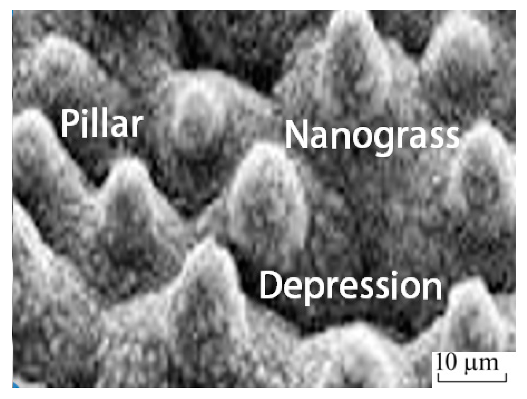
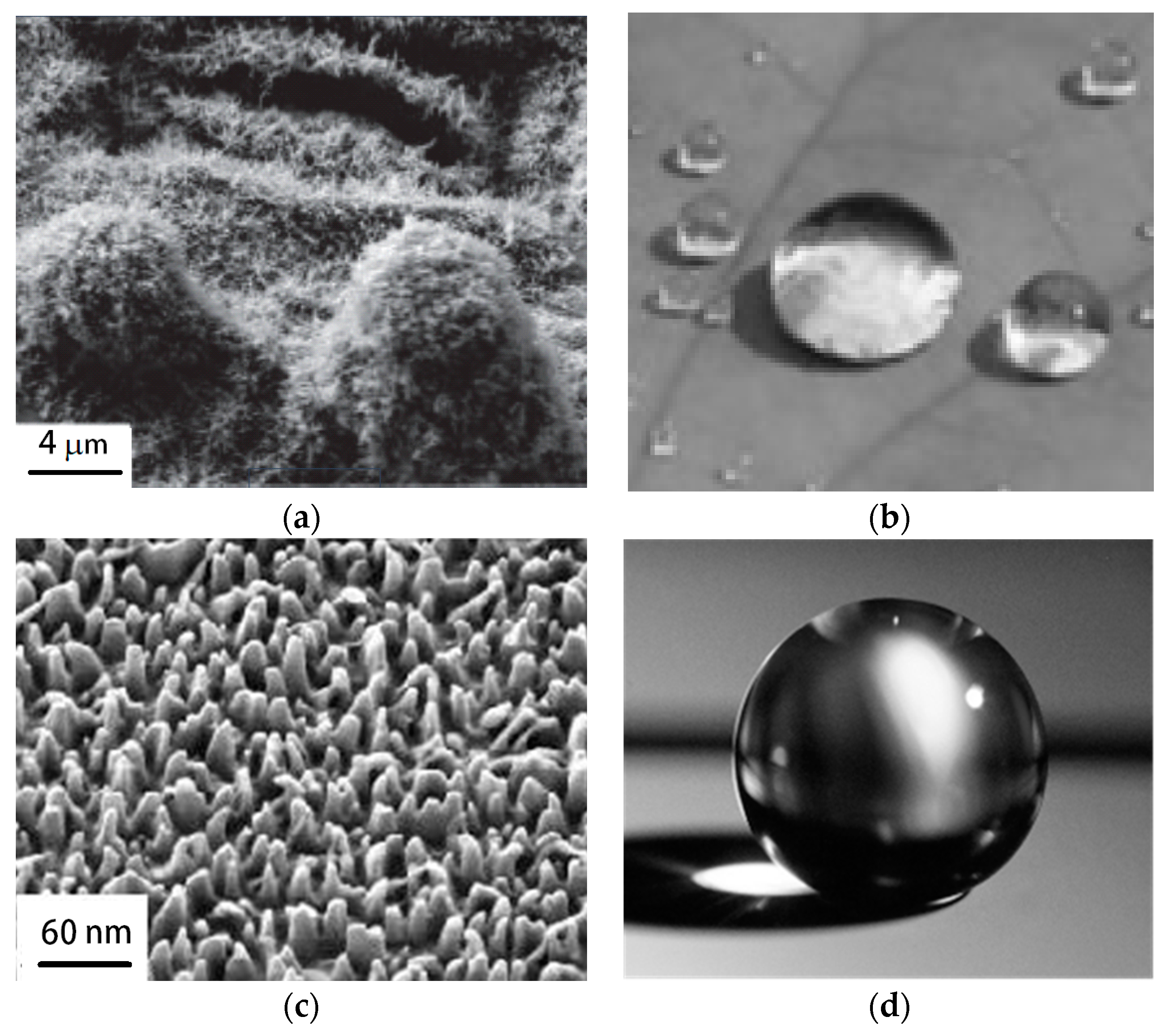
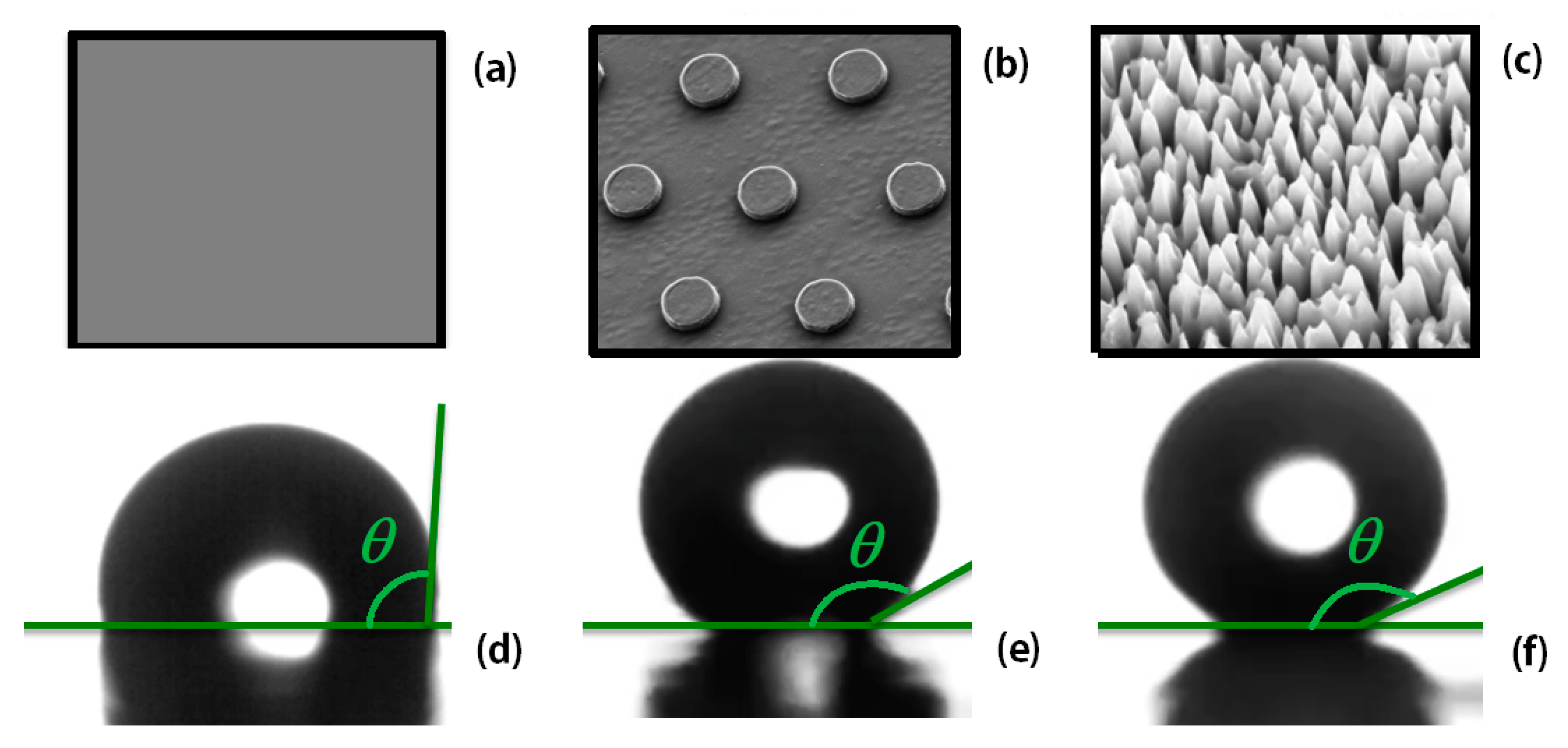
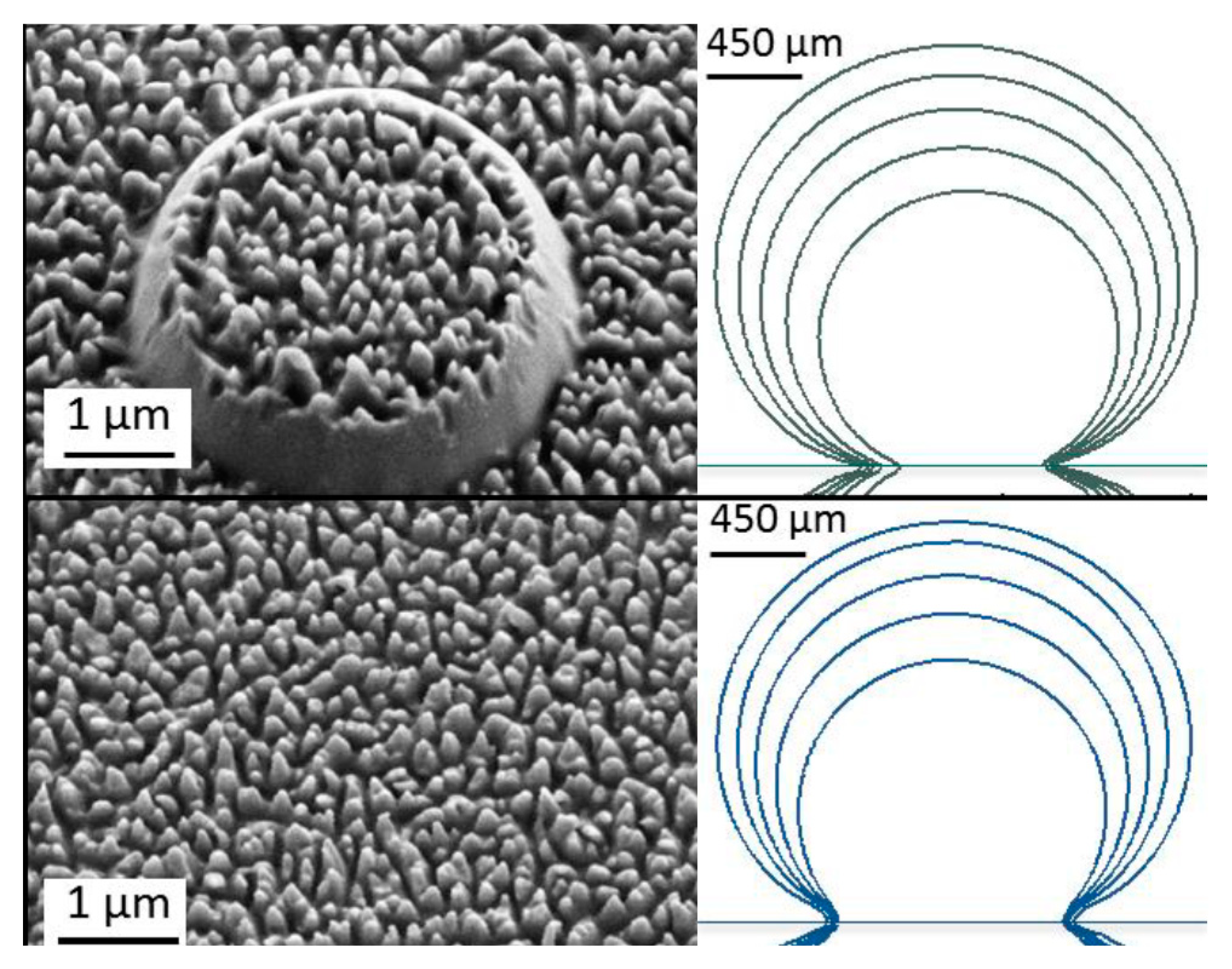
  • A popular solution to combat icing from equipment today is a superhydrophobic coating. Indeed, this type of coating on the rotor blades prevents water adsorption on the surface and icing on the blades. There are numerous research works on this issue, as reported in the last reviews [9]. Thus, this will be the subject of the next section.
Recently, optimization of the operation of wind turbines and wind farms has been increasingly performed to minimize icing in real-time using intelligent control algorithms, described in para. 1–2 above and taking into account changes in external weather conditions, etc. Conditionally, they may be attributed to active physical methods of combating icing. Indeed, they use changes in external physical conditions and optimize the formation of ice by reducing energy production, that is, not through energy consumption, but the loss of energy produced. We will not dwell further on the analysis of this promising direction, since this concept has not yet been fully formed, and its development is a matter of the future.
Paragraphs 3 and 4 are devoted to traditional methods of active anti-icing. Table 1 and Table 2 provide estimates of energy consumption in these methods. The ratio of energy consumption to possible energy produced by an element of the same area indicates the very costly nature of these technologies. A positive balance arises only due to a significant reduction in the operating time of de-icing systems in the full cycle of the wind turbine. Therefore, passive methods are of constant interest to researchers. Currently, the use of superhydrophobic surfaces is becoming increasingly popular (as noted in para. 5). However, their application faces certain difficulties. The next section will attempt to sort out these difficulties.

3. Protection against Icing by a Hydrophobic Material

This part of the review focuses on the essential concept of our consideration basing on water repellent surfaces inspired by natural plants and animals. Many plant leaves or animal skins contain different 3D roughness with complex geometries of nano-and microscale to reduce the flow friction, eliminating the water droplets on the coating, which were used for de-icing special effects in [24,46,47]. The surface structure of the lotus leaf was described in 1997 [48]. Figure 2 shows the elements of the surface structure of the lotus leaf: depressions, pillars, and nanograss separately modeled and studied in [49].
The superhydrophobic surfaces mimicking lotus leaves keep air between the complex roughness and the overlying liquid, having air pockets in the complex structure of the depressions, pillars, and nanograss, which contributes to anti-icing effects [50,51]. The authors of [52] reported that these surfaces enhance the rebound of impacting droplets at low substrate temperatures. Additionally, such coatings can reduce the normal or shear adhesion of ice to the underlying surface [51] resulting in a delay in water freezing on the surface. The use of a hydrophobic coating on the wind turbine blades can prevent water adsorption on the blades and, therefore, ice formation.
These natural structures have been reproduced many times in engineering applications. Synthetic coatings with hydrophobic surfaces due to the water-repellent effect are used to reduce aerodynamic losses, erosion, and icing. Protection against icing of wind turbine blades with the help of such coatings is determined by specific conditions:
  • The hydrophobic coating should effectively reduce the formation of ice and snow.
  • The production of the coating should be simple, cheap, and environmentally friendly.
  • The coating material should be easily mounted or applied to the blade of a wind turbine.
  • This material must be durable to withstand the weather conditions of the Arctic coast. To this end, it must be well tested in a climatic wind tunnel to meet the weather conditions typical for the Arctic coast.
Thus, anti-icing surfaces have to display a comprehensive set of mentioned characteristics.
A great deal of research has been done on this matter. Natural solutions have not been successful for two main reasons: the high cost of producing coatings with nanostructures and the low wear resistance of the roughness. Recent advances in polymer print technology have finally overcome the first challenge. At the same time, the cheapest production of nanomaterials makes it possible to solve the second problem—to comprehensively investigate the change in these surfaces both during static and dynamic interaction with various water flows.
At the end of the last century, polymer embossing was a convenient method for micro structuring [53,54]. The structures made in metals or semiconductor materials can be imprinted into plastic to scale up the production of surfaces with nano- and microstructures. Polymer embossing is now widely used in industrial production lines to create micro-and nano-patterned surfaces [24,55,56]. In addition, the preparation of large textured surfaces is becoming economically viable, and also it does not include toxic chemical reagents, providing an environmentally friendly option.
Today, there are multiple large-scale imprint platforms, such as roll-to-roll (R2R) hot embossing and UV nano-imprint lithography. One of the most promising roll-to-roll imprint platforms is the R2R extrusion coating. This process has a high throughput and the potential to produce imprinted films at a speed of up to 1000 m/min [55,56]. Figure 3 presents schematics of the process.
The process of extrusion coating is a well-known method for the production of packaging films. The introduction of nano- and microstructures on the surfaces of thermo-plastic polymers increases the surface roughness. It changes the properties of wettability and hydrophobicity. The use of such superhydrophobic thermoplastic foils can protect the wind turbine blades from icing and rain impacts and adds self-cleaning properties to the material. This hydrophobic coating is advantageous due to its low cost, which reduces the maintenance cost of wind turbines. Many characteristics specify the functionality of the fabricated foils: the first one is how much the reproduced structures resemble the intended one in the mold. The second problem is the shape and size of the intended nanostructure for each type of extruded polymer. It is essential to provide stable performance for the high speed of the pattern transfer and achieve the consistent quality of the foils.
The authors of [55,56,57] investigated the transfer patterns of micro-and nano-structures between 100 µm down to 50 nm. Several types of structures and the hydrophobic effect are presented in Figure 4. Figure 5 shows the superhydrophobic properties of the lotus leaf and the artificial superhydrophobic surface. The authors of [58] demonstrated the hydrophobic effect in the polymer foils. Hydrophobicity depends on the structure type and size. Figure 4 shows several structures for polymer foils (a–c) and the corresponding contact angles (d–f). For a usual polymer surface without nano-roughness, the water contact angle is 102° ± 1°.
The coating structuring by micropillars changes the contact angle up to 150°; the nano-sized roughness with a random distribution called nanograss further grows the water contact angle to exceed 160° (Figure 4). The difference between the receding and advancing angle or contact angle hysteresis of the nanograss structures is below 10° making these films superhydrophobic.
Figure 5a,b shows the image of the surface leaves of a lotus and a droplet contacting on the surface [47]. Figure 5c,d presents a superhydrophobic polymer surface inspired by leaves of the plants and skins of the animals, with the so-called lotus effect. The rebound of the impacting droplets from the synthetic water-repelling structures resembles the lotus effect of the natural plants.
The next step is to estimate perspectives and difficulties of using the superhydrophobic coating created with this new technology for potential applications of wind energy industries. The imprinted films can be mounted on the blades or directly imprinted on the blade surface; however, a methodology for these techniques is not available in the literature. The surface properties in complex aerodynamic flows should be studied before commencing the development of this technology [47]. The established wear resistance and hydrophobic properties of the nanostructured polymer coatings have to correspond to the characteristics of applications in which friction losses and de-icing are vital. The sought outcome of further investigations should be recommendations on the use of surface coatings.
It is necessary to start the study with the aerodynamics of a single droplet, impacting the wall, since the spraying and rebound of droplets play a critical role in the ice protection of the wind turbine blades. The collision of a liquid drop with a solid surface is associated with many phenomena: droplets can spread, stick, bounce (rebound), splash, etc., as was shown in [61]. The study of the interactions of a droplet hitting a wall is well described in the literature (e.g., [62,63,64,65,66]). Despite experimental progress in solving the droplet impact problem, many of its basic configurations with complex forms have not been studied yet.
The outcome of the drop impact depends on the drop size, impact velocity, the properties of the liquid (its density, viscosity, and viscoelasticity), and from an inclination of the drop trajectory to the surface. The roughness of the solid surface and the non-isothermal effects of solidification and evaporation also have a strong influence. The drop impacting also depends on a dry surface or a thin liquid film on the wall or the free surface of a deep pool. The impact may be perpendicular or oblique (at an angle) [67]. The authors of [61] considered only the case with the normal impact and a spherical liquid drop on a horizontal flat solid substrate as a prototype to define various parameters involved in drop impacts. In general, the impact dynamics were first characterized by the Weber, Reynolds, and Ohnesorge numbers, introducing via the liquid properties as
W e = ρ l D V 2 γ ,   R e = ρ l D V μ l ,   and   O h = μ l V 2 ρ l D γ .
where the normal impact velocity is V, and the drop diameter is D = 2R. The liquid and surrounding gas have densities ρl and ρg, and dynamic (kinematic) viscosities μL (νl = μL/ρl) and μg (νg = μg/ρg), respectively. The gravity is denoted by g and the surface tension by γ, which is oriented along the vertical direction.
We refer to [68] to demonstrate the role of the introduced parameters involved in drop impacts. In this work, the authors proposed a comprehensive analysis of the parameter space (We, Re) to solve the impact problem (Figure 6).
The overview of experimental works in [68] focuses only on droplet impact in industrial requirements for spray/wall interactions in the cooling, cleaning, coating, and combustion because industrial purposes are a priority today (Figure 6). Indeed, inkjet droplets play an increasing role in the different industrial technologies, from the soldering of electronics to microarrays in biotechnology. In nature, however, raindrops hollow out stones or engineering constructions, causing their erosion and icing. In a drizzle, the droplets of 0.2–0.5 mm fall with a velocity of 1–2 m/s, and in a storm, the large drops of 5–9 mm fall with a velocity of 9–30 m/s. Large construction of onshore and offshore wind farms provides an additional level of impact of raindrops on rotating blades at a velocity of 100–150 m/s [47]. These limits for the drops of rain are shown by thick black and gray curves in Figure 6. The additional thin line in Figure 6 indicates the boundary between viscosity-dominated (above from the line) and surface-tension-dominated (below from the line) regimes depending on We and Re. The authors of [9] explain the boundary curve by a competition between both forces in the spreading droplet. The inertia forces drive the liquid to the radial extension when the surface tension (capillarity) pulls back the growing tortilla, and viscous force (viscosity) disperses part of the energy, limiting the maximum spreading size. This curve of the parameter P = (We/Re)4/5 = 1 indicates the limit when the inertia forces are balanced by surface tension and viscous dissipation [69]. Figure 6 does not show the existing droplet experiments for the P > 1 for the rain-scale case providing by using scale-invariant of the tested data.
Finally, there may be other dimensionless parameters in the dynamics, often hard-to-detect in the literature. This may be due to the drop shape (e.g., the aspect ratio of the drop at impact). The strong influence also depends on the substrate properties, in particular, the contact angle θ (Figure 4), roughness distribution describing the hydrophobic properties, and slip velocity Vslip on the surface (Figure 7). The slip velocity and contact angle are usually determined in experiments.
The authors of [70] examined various slip conditions and liquid–solid contact angles at the solid surface to show the importance of roughness and hydrophobicity under the same Re and We. They considered the limit cases with no-slip, Vslip = 0 and free-slip Vslip = U (Figure 7b). They also studied the energy balance and mechanisms of dissipation during the droplet impact on solid surfaces. Their work is important for further calculation of the icing on solid surfaces.
In atmospheric conditions, the splashing raindrops usually consist of the aerosol phase with bounced bubbles [71]. Many attempts exist to describe the splashing effect [72,73,74,75]. Nevertheless, all attempts apply only to cases that do not include the influence of all-natural factors. The difficulty appears in descriptions of the different aerosol phases and the types of surface roughness and their wettability, etc. All experimental parametric studies of the complex phenomena on the splashing of the impacting droplet are necessary to complete by the numerical and theoretical descriptions.
Another well-known review on the impacting drops [63] underlined that a complete characterization of the effect of the surface texture, i.e., roughness and wettability, on the drop evolution, is still to be investigated even for the normal impacts on a dry solid surface. The transition to splashing after an oblique impact of a droplet due to a wind turbine blade still requires experimental research. The review [63] dealt with the droplet impacts on liquid surfaces or wettable walls. The water film appears on the surface during rain. Impacting droplets on thin liquid films deserve a more thorough examination as well. Here, we pay attention to the various effects of the water drops colliding with the liquid films because it is significant for the wind turbine blade under the rain.
Some researchers examined the superhydrophobicity of surfaces under the conditions of extreme condensation revealing their ice-repellent character [76]. The superhydrophobic surface has an anti-icing effect when the time scale of droplet spreading and retracting from the surface is smaller than the time of the ice nucleation [52]. A dimensionless number, the Weber number, may be used to examine droplet icing. There is a critical Weber number when the impacting droplets could not completely bounce off [77]. The authors of [78] developed a special topography for the superhydrophobic surfaces that redistributes the liquid mass with a very small contact time of a bouncing drop, which is below the theoretical limit based on the Rayleigh time scale.
Using new technical materials with super-hydrophobic properties is a popular topic for much research on de-icing [79,80,81,82,83]. Several studies of freezing water droplets on cooled super-hydrophobic surfaces were carried out on samples of relatively expensive components, such as microstructured fluorinated Al, Si, or Gold Thiols [52,84]. However, these successful solutions for such surface coatings due to the high cost of their fabrication are hard to reproduce in many engineering tasks.
The plastic coatings mentioned above are easy to use for various engineering tasks that require establishing and testing new anti-icing/rain solutions in the complex aerodynamic flows and should take into account the main aspects of the previous water-repellent or de-icing investigations. The studies described here have mainly focused on testing the lotus effect without the icing effect [56]. A water droplet impacting the flat plastic foil does not reach a complete rebound and stays pinned to the surface but a superhydrophobic surface with nanograss structures provides a total rebound after the impact with a similar water droplet. Figure 8 demonstrates the lotus effect, which is explained by superhydrophobicity. Different polymer types show different results, depending on the structures of the roughness and the initial contact angle with water.
The authors of [24] described one more problem of superhydrophobic surfaces mimicking the lotus effect. The surfaces are designed to reproduce a topography of the lotus leaves on the micro- to nano-scale for which air keeps between the surface texture and the overlying liquid (named the Cassie or Cassie–Baxter state [84]). Nevertheless, liquid droplets on a rough surface could also exist in the Wenzel state [85,86] when the liquid droplet displaces the air and wetting surface.
In the first case, trapped air in the textures of supercooling surface results in the impacting water droplets bouncing off before freezing. Some researchers claimed that a lower ice adhesion strength on superhydrophobic surfaces indicates the water freezing in the Cassie–Baxter state and the formation of a ‘Cassie ice’ or frost [87]. A reduction in the contact area between the ice and the solid substrate in the Cassie ice-state reduces the ice adhesion strength. The growth of the contact area due to surface topography in a Wenzel ice state leads to an increase in the total ice adhesion strength. These authors argued that effective ice-phobic surfaces must resist transitions to the wetted Wenzel state.
The Wenzel case is significant for understanding the icing processes but still lacks practical results. Recently, the Wenzel case of the interaction of the fluid with a polymer nanosurface without an “air” interlayer between them indicates a growth of surface tension, which increases the size of the generated vortex by 5–11%. The polymer foils have nanoroughnesses simulating the superhydrophobic surface of a lotus leaf (Figure 9) [56,88].
The results obtained are of interest for the further development of this technology. Future research should concern the determination and design of optimal super-hydrophobic surfaces among various micro-and nanostructured patterns. Furthermore, it is necessary to investigate how complex aerodynamic flows may change the hydrophobic properties of the polymer foils, since previous studies, as a rule, dealt only with the interaction of the resting or free-falling droplets on super-hydrophobic surfaces.
At the end of the review, we agree with [89] that, despite recent advances, simple anti-icing technologies that can prevent or delay the formation, accumulation, and adhesion of glaze, rime, frost, bulk ice, and dry/wet snow or their combinations are still missing. In further investigations, researchers should study how airflow around rotor blades influences the contact time and the contact area of impinging water droplets for various plastic super-hydrophobic coatings.

4. Conclusions

In the current study, we reflected on three main areas in the de-icing of wind turbines:
-
a promising and rapidly developing direction with the use of intelligent technologies that reduce icing by selecting operating modes taking into account climatic conditions and other external energy sources in real-time;
-
traditional active ice removal technologies: heating, vibration, ultrasonic exposure, and their combinations; and
-
passive methods of de-icing.
It should be noted that the development of the first direction will likely become successful in the near future; the second direction remains the most effective, but is accompanied by high energy costs; the success of passive methods of de-icing is now associated with the use of superhydrophobic materials, but there are no effective engineering solutions yet.
This review focused on describing the difficulties associated with the use of the latter direction, that is, the use of superhydrophobic surfaces to protect wind turbine blades from icing. The high cost of producing and applying superhydrophobic micro-and nanostructures to the surface of the blade at the present stage can be successfully overcome by using lithographic technologies for plastic coatings. A significant factor currently hindering their use is the backlog of scientific research to determine their hydrophobic and anti-icing properties.
Thus far, many studies on the use of the lotus effect have been limited to testing only one drop falling separately on a part of the surface. Even this model problem is still far from being fully solved since the dynamics of the impact demonstrate different behavior depending on the numerous parameters of the impact and the substrate. The effect of spraying on de-icing treatment under normal impacts of a drop on a thin layer of liquid is insufficiently described in the literature.
The propagation of individual droplets falling at an angle also requires additional research and elaboration of appropriate theories. This is a typical problem when drops fall at an angle on the surface of the blade that has not been solved yet. Moreover, it is necessary to move from the study of individual droplets to a more intense investigation of the effect of cooled aerosol droplet flow on the profiles of wind turbine blades in climatic wind tunnels.
As for the production of blades with nanostructured surfaces, the current review proposes to use a coating based on a thermoplastic polymer as a new idea to protect them from water/ice erosion. In practice, this can be achieved with the help of a new technology of polymer embossing on plastic surface coatings. This original approach may be simple and inexpensive and may open the way for current and new applications. This should be actively tested and verified, both experimentally in climatic wind tunnels and theoretical studies over the next few years, to study the lotus effect in conditions of heavy rain and icing.

Author Contributions

Conceptualization, V.O. and N.O.; writing—original draft preparation, V.O.; writing—review and editing, V.O., I.K., D.M., K.S. and N.O; supervision, V.O.; project administration, I.K.; funding acquisition, IT. All authors have read and agreed to the published version of the manuscript.

Funding

This research was funded by Russian Science Foundation, grant number 21-19-00205.

Institutional Review Board Statement

Not applicable.

Informed Consent Statement

Not applicable.

Data Availability Statement

Not applicable.

Acknowledgments

The study is a part of the international academic and research program for studying the icing of constructions in cold regions CoARICE.

Conflicts of Interest

The authors declare no conflict of interest.

References

  1. BTM World Market Update 2012. Navigant Research 2013. Available online: https://www.businesswire.com/news/home/20130326005329/en/Navigant-Research-Releases-New-BTM-Wind-Report-World-Market-Update-2012 (accessed on 26 March 2013).
  2. Elistratov, V.; Kudryashova, I.; Pilipets, P. Energy efficient solutions of power supply in north regions. Appl. Mech. Mater. 2015, 725, 559–568. [Google Scholar] [CrossRef]
  3. Osintsev, K.; Aliukov, S.; Shishkov, A. Improvement dependability of offshore horizontal-axis wind turbines by applying new mathematical methods for calculation the excess speed in case of wind gusts. Energies 2021, 14, 3085. [Google Scholar] [CrossRef]
  4. Liu, Y.; Li, Q.; Farzaneh, M.; Du, B.X. Image characteristic extraction of ice-covered outdoor insulator for monitoring icing degree. Energies 2020, 13, 5305. [Google Scholar] [CrossRef]
  5. Rastayesh, S.; Long, L.; Dalsgaard Sørensen, J.; Thöns, S. Risk assessment and value of action analysis for icing conditions of wind turbines close to highways. Energies 2019, 12, 2653. [Google Scholar] [CrossRef] [Green Version]
  6. Demartino, C.; Koss, H.H.; Georgakis, C.T.; Ricciardelli, F. Effects of ice accretion on the aerodynamics of bridge cables. J. Wind Eng. Ind. Aerodyn. 2015, 138, 98–119. [Google Scholar] [CrossRef]
  7. Gantasala, S.; Tabatabaei, N.; Cervantes, M.; Aidanpää, J.-O. Numerical investigation of the aeroelastic behavior of a wind turbine with iced blades. Energies 2019, 12, 2422. [Google Scholar] [CrossRef] [Green Version]
  8. Turkia, V.; Huttunen, S.; Thomas, W. Method for Estimating Wind Turbine Production Losses Due to Icing; VTT Technical Research Centre of Finland: Espoo, Finland, 2013. [Google Scholar]
  9. Wei, K.; Yang, Y.; Zuo, H.; Zhong, D. A review on ice detection technology and ice elimination technology for wind turbine. Wind Energy 2020, 23, 433–457. [Google Scholar] [CrossRef]
  10. Kazem, H.A.; Al-Badi, H.A.S.; Al Busaidi, A.S.; Chaichan, M.T. Optimum design and evaluation of hybrid solar/wind/diesel power system for Masirah Island. Environ. Dev. Sustain. 2017, 19, 1761–1778. [Google Scholar] [CrossRef]
  11. Elistratov, V.; Konishchev, M.; Denisov, R.; Bogun, I.; Grönman, A.; Turunen-Saaresti, T.; Lugo, A.J. Study of the intelligent control and modes of the arctic-adopted wind–diesel hybrid system. Energies 2021, 14, 4188. [Google Scholar] [CrossRef]
  12. Janzon, E.; Körnich, H.; Arnqvist, J.; Rutgersson, A. Single column model simulations of icing conditions in northern Sweden: Sensitivity to surface model land use representation. Energies 2020, 13, 4258. [Google Scholar] [CrossRef]
  13. Yang, X.; Ye, T.; Wang, Q.; Tao, Z. Diagnosis of blade icing using multiple intelligent algorithms. Energies 2020, 13, 2975. [Google Scholar] [CrossRef]
  14. Molinder, J.; Scher, S.; Nilsson, E.; Körnich, H.; Bergström, H.; Sjöblom, A. Probabilistic forecasting of wind turbine icing related production losses using quantile regression forests. Energies 2021, 14, 158. [Google Scholar] [CrossRef]
  15. Etemaddar, M.; Hansen, M.O.L.; Moan, T. Wind turbine aerodynamic response under atmospheric icing conditions. Wind Energy 2014, 17, 241–265. [Google Scholar] [CrossRef]
  16. Villalpando, F.; Reggio, M. Prediction of ice accretion and anti-icing heating power on wind turbine blades using standard commercial software. Energy 2016, 114, 1041–1052. [Google Scholar] [CrossRef]
  17. Shu, L.; Qiu, G. Numerical and experimental investigation of threshold de-icing heat flux of wind turbine. J. Wind. Eng. Ind. Aerodyn. 2018, 174, 296–302. [Google Scholar] [CrossRef]
  18. Hu, L.; Zhu, X. Wind turbines ice distribution and load response under icing conditions. Renew. Energy 2017, 113, 608–619. [Google Scholar] [CrossRef]
  19. Shu, L.; Li, H. Study of ice accretion feature and power characteristics of wind turbines at natural icing environment. Cold Reg. Sci. Technol. 2018, 147, 45–54. [Google Scholar] [CrossRef]
  20. Parent, O.; Ilinca, A. Anti-icing and de-icing techniques for wind turbines: Critical review. Cold Reg. Sci. Technol. 2011, 65, 88–96. [Google Scholar] [CrossRef]
  21. Habibi, H.; Edwards, G. Modelling and empirical development of an anti/de-icing approach for wind turbine blades through superposition of different types of vibration. Cold Reg. Sci. Technol. 2016, 128, 1–12. [Google Scholar] [CrossRef] [Green Version]
  22. Batisti, L. Green Energy and Technology. Icing Impacts and Mitigation System; Springer: Cham, Switzerland, 2015; p. 355. ISSN 1865-3529. [Google Scholar]
  23. Wang, Y.; Xu, Y.; Huang, Q. Progress on ultrasonic guided waves de-icing techniques in improving aviation energy efficiency. Renew. Sustain. Energy Rev. 2017, 83, 638–645. [Google Scholar] [CrossRef]
  24. Wang, Y.; Xu, Y. An effect assessment and prediction method of ultrasonic de-icing for composite wind turbine blades. Renew. Energy 2018, 118, 1015–1023. [Google Scholar] [CrossRef]
  25. Wang, Z. Recent progress on ultrasonic de-icing technique used for wind power generation, high-voltage transmission line and aircraft. Energy Build 2017, 140, 42–49. [Google Scholar] [CrossRef]
  26. Madi, E.; Pope, K.; Huang, W.; Iqbal, K. A review of integrating ice detection and mitigation for wind turbine blades. Renew. Sustain. Energy Rev. 2019, 103, 269–281. [Google Scholar] [CrossRef]
  27. Ilinca, A. Analysis and mitigation of icing effects on wind turbines. In Wind Turbines; Al-Bahadly, I., Ed.; In Tech: Rijeka, Croatia, 2011; p. 177. [Google Scholar] [CrossRef] [Green Version]
  28. Sojoudi, H.; Wang, M.; Boscher, N.D.; McKinley, G.H.; Gleason, K.K. Durable and scalable icephobic surfaces: Similarities and distinctions from superhydrophobic surfaces. Soft Matter 2016, 12, 1938–1963. [Google Scholar] [CrossRef] [PubMed] [Green Version]
  29. Suke, P. Analysis of Heating Systems to Mitigate Ice Accretion on Wind Turbine Blades. Master’s Thesis, McMaster University, Hamilton, ON, Canada, 2014. [Google Scholar]
  30. Varentsov, M.I.; Repina, I.A.; Artamonov, A.Y.; Khavina, E.M.; Matveeva, T.A. Experimental Studies of the Energy Exchange and Dynamics of the Atmospheric Boundary Layer in the Arctic in the Summer Period; RF Hydrometeorological Research Center: Moscow, Russia, 2016; Volume 361, pp. 95–127. [Google Scholar]
  31. Repina, I.A.; Chechin, D.G. Influence of ice holes and flaw leads in the Arctic on the structure of the atmospheric boundary layer and regional climate. Mod. Probl. Remote. Sens. Earth Space 2012, 9, 162–170. [Google Scholar]
  32. Repina, I.A.; Aliferov, A.A. Study of dynamics of the atmospheric boundary layer over a coastal flaw lead of the Laptev Sea based on the data of WRF modeling. Mod. Probl. Remote. Sens. Earth Space 2018, 15, 282–295. [Google Scholar]
  33. Fiedler, E.K.; Lachlan-Cope, T.A.; Renfrew, I.A.; King, J.C. Convective heat transfer over thin ice covered coastal polynyas. J. Geophys. Res. 2010, 115, C10051. [Google Scholar] [CrossRef] [Green Version]
  34. Ebner, L.; Schroder, D.; Heineman, G. Impact of Laptev Sea flaw polynyas on the atmospheric boundary layer and ice production using idealized mesoscale simulations. Polar Res. 2011, 30, 7210. [Google Scholar] [CrossRef]
  35. Sabatier, J.; Lanusse, P. CRONE control based anti-icing/de-icing system for wind turbine blades. Control. Eng. Pract. 2016, 56, 200–209. [Google Scholar] [CrossRef]
  36. Hung, C.; Dillehay, M.E.; Stahl, M. A heater made from graphite composite material for potential de-icing application. J Aircr. 1987, 24, 725–730. [Google Scholar] [CrossRef]
  37. Dalili, N.; Edrisy, A.; Carriveau, R. A review of surface engineering issues critical to wind turbine performance. Renew. Sustain. Energy Rev. 2009, 13, 428–438. [Google Scholar] [CrossRef]
  38. Stoyanov, D.B. Analysis of derating and anti-icing strategies for wind turbines in cold climates. Appl. Energy 2021, 288, 116610. [Google Scholar] [CrossRef]
  39. Thompson, G.; Nygaard, B.E.; Makkonen, L.; Dierer, S. Using the Weather Research and Forecasting (WRF) model to predict ground/structural icing. In Proceedings of the XIII International Workshop on Atmospheric Icing of Structures (IWAIS), Andermatt, Switzerland, 8–11 September 2009. [Google Scholar]
  40. Gao, H.; Rose, J.L. Ice detection and classification on an aircraft wing with ultrasonic shear horizontal guided waves. IEEE Trans. Ultrason. Ferroelectr. Freq. Control 2009, 56, 334–344. [Google Scholar] [PubMed]
  41. Overmeyer, A.; Palacios, J.; Smith, E. Ultrasonic de-icing bondline design and rotor ice testing. AIAA J. 2013, 51, 2965–2976. [Google Scholar] [CrossRef]
  42. Palacios, J.; Smith, E.; Rose, J.; Royer, R. Instantaneous de-icing of freezer ice via ultrasonic actuation. AIAA J. 2011, 49, 1158–1167. [Google Scholar] [CrossRef] [Green Version]
  43. Palacios, J.; Smith, E.; Rose, J.; Royer, R. Ultrasonic de-icing of wind-tunnel impact icing. J Aircr. 2011, 48, 1020–1027. [Google Scholar] [CrossRef]
  44. Habibi, H.; Cheng, L.; Zheng, H.; Kappatos, V.; Selcuk, C.; Gan, T.H. A dual de-icing system for wind turbine blades combining high-power ultrasonic guidedwaves and low-frequency forced vibrations. Renew. Energy 2015, 83, 859–870. [Google Scholar] [CrossRef] [Green Version]
  45. Itagaki, K. Mechanical Ice Release Processes: I. Self-Shedding from High-Speed Rotors; CCREL Report: Hanover, NH, USA, 1983; Volume 83. [Google Scholar]
  46. Laforte, C.; Laforte, J.L. How a solid coating can reduce ice adhesion on structures. In Proceedings of the 10th International Workshop of AtmosphericIcing of Structures, Brno, Czech Republic, 17–21 June 2002. [Google Scholar]
  47. Okulova, N.; Taboryski, R.; Sørensen, J.N.; Shtork, S.I.; Okulov, V.L. Aerodynamic effect of icing/rain impacts on super-hydrophobic surfaces. In Proceedings of the AIP Conference; Novosibirsk, Russia AIP Publishing LLC: Melville, NY, USA, 13–19 August 2018; Volume 2027, p. 030045. [Google Scholar]
  48. Barthlott, W.; Neinhuis, C. Purity of the sacred lotus, or escape from contamination in biological surfaces. Planta 1997, 202, 1–8. [Google Scholar] [CrossRef]
  49. Naumov, I.V.; Okulova, N.V.; Sharifullin, B.R.; Lomakinaa, V.A.; Okulov, V.L. Experimental investigation of the effect of nano- and microroughnesses on the intensity of swirled flow. Dokl. Phys. 2021, 66, 118–121. [Google Scholar]
  50. Kulinich, S.A.; Farzaneh, M. How wetting hysteresis influences ice adhesion strength on superhydrophobic surfaces. Langmuir 2009, 25, 8854–8856. [Google Scholar] [CrossRef] [PubMed]
  51. Sarkar, D.K.; Farzaneh, M. Superhydrophobic coatings with reduced ice adhesion. J. Adhes. Sci. Technol. 2009, 23, 1215–1237. [Google Scholar] [CrossRef]
  52. Mishchenko, L.; Hatton, B.; Bahadur, V.; Taylor, J.A.; Krupenkin, T.; Aizenberg, J. Design of ice-free nanostructured surfaces based on repulsion of impacting water droplets. ACS Nano 2010, 4, 7699–7707. [Google Scholar] [CrossRef] [PubMed]
  53. Chou, S.Y.; Krauss, P.R.; Renstrom, P.J. Imprint of sub-25 nm vias and trenches in polymers. Appl. Phys. Lett. 1995, 67, 3114. [Google Scholar] [CrossRef] [Green Version]
  54. Heckele, M.; Bacher, W.; Müller, K. Hot embossing—The molding technique for plastic microstructures. Microsyst. Technol. 1998, 4, 122–124. [Google Scholar] [CrossRef]
  55. Murthy, S.; Matschuk, M.; Huang, Q.; Mandsberg, N.K.; Feidenhans’l, N.A.; Johansen, P.; Christensen, L.; Pranov, H.; Kofod, G.; Pedersen, H.C.; et al. Fabrication of nanostructures by roll-to-roll extrusion coating. Adv. Eng. Mater. 2016, 18, 484–489. [Google Scholar] [CrossRef] [Green Version]
  56. Okulova, N. Industrial-Scale Pattern Transfer Using Roll-to-Roll Extrusion Coating: Understanding the Process and Exploring its Applications. Ph.D. Thesis, Technical University of Denmark, Lyngby, Denmark, 2018. [Google Scholar]
  57. Okulova, N.; Johansen, P.; Christensen, L.; Taboryski, R.J. Replication of micro-sized pillars in polypropylene using the extrusion coating process. Microelectron. Eng. 2017, 176, 54–57. [Google Scholar] [CrossRef] [Green Version]
  58. Telecka, A.; Murthy, S.; Sun, L.; Pranov, H.; Taboryski, R.J. Superhydrophobic properties of nanotextured polypropylene foils fabricated by roll-to-roll extrusion coating. ACS Macro Lett. 2016, 5, 1034–1038. [Google Scholar] [CrossRef] [Green Version]
  59. Wijesena, R. How Lotus Leaf Make Water Droplets Dance on Its Surface. Available online: http://ninithi.com (accessed on 30 July 2015).
  60. Søgaard, E. Injection Molded Self-Cleaning Surfaces. Ph.D. Thesis, DTU Nanotech, Lyngby, Denmark, 2014; p. 230. [Google Scholar]
  61. Josserand, C.; Thoroddsen, S.T. Drop impact on a solid surface. Annu. Rev. Fluid Mech. 2016, 48, 365–391. [Google Scholar] [CrossRef] [Green Version]
  62. Rein, M. Phenomena of liquid drop impact on solid and liquid surfaces. Fluid Dyn. Res. 1993, 12, 61–93. [Google Scholar] [CrossRef]
  63. Yarin, A.L. DROP IMPACT DYNAMICS: Splashing, spreading, receding, bouncing…. Annu. Rev. Fluid Mech. 2006, 38, 159–192. [Google Scholar] [CrossRef]
  64. Marengo, M.; Antonini, C.; Roisman, I.V.; Tropea, C. Drop collisions with simple and complex surfaces (Review). Opin. Colloid Interface Sci. 2011, 16, 292–302. [Google Scholar] [CrossRef]
  65. Quere, D. Leidenfrost dynamics. Annu. Rev. Fluid Mech. 2013, 45, 197–215. [Google Scholar] [CrossRef] [Green Version]
  66. Thoroddsen, S.T.; Etoh, T.G.; Takehara, K. High-speed imaging of drops and bubbles. Annu. Rev. Fluid Mech. 2008, 40, 257–285. [Google Scholar] [CrossRef]
  67. Chen, C.-K.; Chen, S.-Q.; Yan, W.-M.; Li, W.-K.; Lin, T.-H. Experimental study on two consecutive droplets impacting onto an inclined solid surface. J. Mech. 2021, 37, 432–445. [Google Scholar] [CrossRef]
  68. Visser, C.W.; Frommhold, P.E.; Wildeman, S.; Mettin, R.; Lohse, D.; Sun, C. Dynamics of high-speed micro-drop impact: Numerical simulations and experiments at frame-to-frame times below 100 ns. Soft Matter 2015, 11, 1708–1722. [Google Scholar] [CrossRef] [Green Version]
  69. Clanet, C.; Beguin, C.; Richard, D.; Quere, D. Maximal deformation of an impacting drop. J. Fluid Mech. 2004, 517, 199–208. [Google Scholar] [CrossRef]
  70. Wildeman, S.; Visser, C.; Sun, C.; Lohse, D. On the spreading of impacting drops. J. Fluid Mech. 2016, 805, 636–655. [Google Scholar] [CrossRef] [Green Version]
  71. Joung, Y.; Buie, C. Aerosol generation by raindrop impact on soil. Nat. Commun. 2015, 6, 6083. [Google Scholar] [CrossRef] [Green Version]
  72. Duchemin, L.; Josserand, C. Rarefied gas correction for the bubble entrapment singularity in drop impacts. Comptes Rendus Mec. 2012, 340, 797–803. [Google Scholar] [CrossRef] [Green Version]
  73. Mandre, S.; Brenner, M. The mechanism of a splash on a dry solid surface. J. Fluid Mech. 2012, 690, 148–172. [Google Scholar] [CrossRef]
  74. Palacios, J.; Hernández, J.; Gómez, P.; Zanzi, C.; López, J. Experimental study of splashing. Exp. Therm. Fluid Sci. 2013, 44, 571–582. [Google Scholar] [CrossRef]
  75. Riboux, G.; Gordillo, J.M. Experiments of drops impacting a smooth solid surface: A model of the critical impact speed for drop splashing. Phys. Rev. Lett. 2014, 113, 024507. [Google Scholar] [CrossRef] [PubMed]
  76. Wang, Y.; Xue, J.; Wang, Q.; Chen, Q.; Ding, J. Verification of icephobic/anti-icing properties of a superhydrophobic surface. ACS Appl. Mater. Interfaces 2013, 5, 3370–3381, Epub 12 April 2013. [Google Scholar] [CrossRef] [PubMed]
  77. Maitra, T.; Tiwari, M.K.; Antonini, C.; Schoch, P.; Jung, S.; Eberle, P.; Poulikakos, D. On the nanoengineering of superhydrophobic and impalement resistant surface textures below the freezing temperature. Nano Lett. 2014, 14, 172–182. [Google Scholar] [CrossRef] [PubMed]
  78. Bird, J.C.; Dhiman, R.; Kwon, H.M.; Varanasi, K.K. Reducing the contact time of a bouncing drop. Nature 2013, 503, 385–388. [Google Scholar] [CrossRef] [PubMed]
  79. Campos, R.; Guenthner, A.J.; Meuler, A.J.; Tuteja, A.; Cohen, R.E.; McKinley, G.H.; Haddad, T.S.; Mabry, J.M. Superoleophobic surfaces through control of sprayed-on stochastic topography. Langmuir 2012, 28, 9834–9841. [Google Scholar] [CrossRef]
  80. Hsieh, C.T.; Cheng, Y.S.; Hsu, S.M.; Lin, J.Y. Water and oil repellency of flexible silica-coated polymeric substrates. Appl. Surf. Sci. 2010, 256, 4867–4872. [Google Scholar] [CrossRef]
  81. Wu, X.; Fu, Q.; Kumar, D.; Ho, J.W.C.; Kanhere, P.; Zhou, H.; Chen, Z. Mechanically robust superhydrophobic and superoleophobic coatings derived by sol-gel method. Mater. Des. 2016, 89, 1302–1309. [Google Scholar] [CrossRef]
  82. Söz, C.K.; Yilgör, E.; Yilgör, I. Influence of the coating method on the formation of superhydrophobic silicone–urea surfaces modified with fumed silica nanoparticles. Prog. Org. Coat. 2015, 84, 143–152. [Google Scholar] [CrossRef]
  83. Yilgör, E.; Söz, C.K.; Yilgör, I. Wetting behavior of superhydrophobic poly (methyl methacrylate). Prog. Org. Coat. 2018, 125, 530–536. [Google Scholar] [CrossRef]
  84. Cassie, A.B.D.; Baxter, S. Wettability of porous surfaces. Trans. Faraday Soc. 1944, 40, 0546–0550. [Google Scholar] [CrossRef]
  85. Gao, L.C.; McCarthy, T.J. Wetting 101°. Langmuir 2009, 25, 14105–14115. [Google Scholar] [CrossRef] [PubMed]
  86. Marmur, A. Wetting on hydrophobic rough surfaces:  To be heterogeneous or not to be? Langmuir 2003, 19, 8343–8348. [Google Scholar] [CrossRef]
  87. Meuler, A.J.; McKinley, G.H.; Cohen, R.E. Exploiting topographical texture to impart icephobicity. ACS Nano 2010, 4, 7048–7052. [Google Scholar] [CrossRef] [Green Version]
  88. Okulova, N.; Johansen, P.; Christensen, L.; Taboryski, R. Effect of structurehierarchy for superhydrophobic polymer surfaces studied by droplet evaporation. Nanomaterial 2018, 8, 531. [Google Scholar] [CrossRef] [Green Version]
  89. Sun, X.; Damle, V.G.; Liu, S.; Rykaczewski, K. Bioinspired stimuli-responsive and antifreeze-secreting anti-icing coatings. Adv. Mater. Interfaces 2015, 2, 1400479. [Google Scholar] [CrossRef]
Figure 1. Examples of wind turbine icing.
Energies 14 06750 g001
Figure 2. Example of the surface structure of the lotus leaf.
Energies 14 06750 g002
Figure 3. A scheme of the R2R extrusion coating procedure: the designed patterns of the nanostructure put to the “Cooling Roll”, where the heated polymer is contacted with the “Cooling Roll” by the “Pressure Roll”.
Energies 14 06750 g003
Figure 4. The plastic surfaces: (a) flat, (b) micropillars, (c) nano-needles (ac) represent the structure of the roughness and (df) represent the measurements of the corresponding contact angle.
Energies 14 06750 g004
Figure 5. The lotus effect: (a) roughness structure on the surface of a lotus leaf [59]; (b) a droplet of water on the super-hydrophobic leaf indicating the lotus effect [60]. (c) A synthetic roughness surface manufactured in the lab and mimicking the lotus-leaf structure; (d) a droplet of water on the synthetic superhydrophobic surface (Photo by Jesper Scheel).
Energies 14 06750 g005
Figure 6. Possible places in the frame of Reynolds and Weber numbers for raindrops impacting to the ground (black thick line) and on blades of wind turbines (grey thick line). The data are shown in comparison with experimental works on droplet impact for different setups where the P-line shows the boundary between dominated regimes of viscosity (P < 1) and surface tension (P > 1).
Energies 14 06750 g006
Figure 7. Types of different drop interactions with a surface (a), and a draft of the slip velocity on the wall (b).
Energies 14 06750 g007
Figure 8. A water droplet impacting a simple plastic foil surface (upper row). A water droplet impacting a nanostructured surface of the foil manufactured by the roll-to-roll extrusion technology (low row). In the first case, the droplet is pinned to the surface; at the same time for the second case, the droplet rebounded from the superhydrophobic foil.
Energies 14 06750 g008
Figure 9. Structures of micropillars with nanograss and pure nanograss simulating a lotus leaf with the respective evaporating droplet profiles.
Energies 14 06750 g009
Table 1. Indicators of energy efficiency of anti-icing systems of wind generators with a rated power of up to 100 kW 1.
ParameterThermal Method 2Ultrasonic MethodCombined Method (Ultrasonic + Vibration)
Power 3, W/cm 4.180.63No data
Ratio 4, %1223.2
1 the table based on the data from [23]. 2 surface-mounted thermoelectric heating element. 3 installation of vibration mechanisms in characteristic areas of the blade for ice dumping. 4 the share of the power consumption of the protection system from the rated power of the wind generator.
Table 2. Indicators of energy efficiency of anti-icing systems of wind generators with a rated power of up to 220 kW, recalculated following the indicators of various anti-icing systems for the Bell 412 helicopter 1.
ParameterThermal Method 1Ultrasonic MethodImpulsive Method Vibratory MethodMicrowave Method
Ratio 2, %121.91.40.67
1 the table based on the data from [23]. 2 the share of the power consumption of the protection system from the rated power of the wind generator.
Publisher’s Note: MDPI stays neutral with regard to jurisdictional claims in published maps and institutional affiliations.

