Review

Electrospun Composite Proton-Exchange and Anion-Exchange Membranes for Fuel Cells

Department of Chemical and Biomolecular Engineering, Vanderbilt University, Nashville, TN 37235, USA
*
Authors to whom correspondence should be addressed.
Energies 2021, 14(20), 6709; https://doi.org/10.3390/en14206709
Submission received: 2 September 2021 / Revised: 3 October 2021 / Accepted: 11 October 2021 / Published: 15 October 2021

Abstract

:
A fuel cell is an electrochemical device that converts the chemical energy of a fuel and oxidant into electricity. Cation-exchange and anion-exchange membranes play an important role in hydrogen fed proton-exchange membrane (PEM) and anion-exchange membrane (AEM) fuel cells, respectively. Over the past 10 years, there has been growing interest in using nanofiber electrospinning to fabricate fuel cell PEMs and AEMs with improved properties, e.g., a high ion conductivity with low in-plane water swelling and good mechanical strength under wet and dry conditions. Electrospinning is used to create either reinforcing scaffolds that can be pore-filled with an ionomer or precursor mats of interwoven ionomer and reinforcing polymers, which after suitable processing (densification) form a functional membrane. In this review paper, methods of nanofiber composite PEMs and AEMs fabrication are reviewed and the properties of these membranes are discussed and contrasted with the properties of fuel cell membranes prepared using conventional methods. The information and discussions contained herein are intended to provide inspiration for the design of high-performance next-generation fuel cell ion-exchange membranes.

Graphical Abstract

1. Introduction

With the inevitable depletion of fossil fuels, such as coal and oil, and the increasingly stringent requirements for reduction of greenhouse gas emissions, it is urgent to seek environmentally friendly, renewable energy sources that can replace conventional carbon-based systems. Green energy such as solar, tidal, wind, biomass, geothermal, hydro, nuclear, and hydrogen (H2) can be used to address our future needs, for addressing climate change and mitigating global warming. Some green energy sources such as tidal, wind, and solar, however, fluctuate over time resulting in intermittent power generation. Electrochemical batteries can be coupled to green energy sources to address this problem [1]. Fuel cells have important applications in the automotive and heavy-duty vehicle transportation sector, as an environmentally clean alternative to the internal combustion engine and a long drive-distance alternative to Li-ion batteries. Fuel cells convert the chemical energy of a fuel and oxidant into electrical energy at efficiencies that are typically higher than those achieved in an internal combustion engine. One type of fuel cell uses H2 as the fuel, with only water as the reaction product. Such a carbon-free and potentially reversible energy system (where hydrogen is regenerated by water electrolysis) is highly desirable. Hydrogen fuel cells are being considered for a variety of different applications, including power plants in passenger and heavy-duty vehicles and for distributed electricity generators [2].
According to the type of electrolyte, fuel cells can be divided into proton-exchange membrane fuel cells (PEMFCs), anion-exchange membrane fuel cells (AEMFCs, which are sometimes referred to as hydroxide-exchange membrane fuel cells), solid oxide fuel cells (SOFCs), molten carbonate fuel cells (MCFCs), and phosphoric acid fuel cells (PAFCs) [3]. In this article, various types of polymeric membranes used in H2 gas-fueled PEMFCs and AEMFCs will be described, with a focus on their composition, methods of fabrication, and those properties that are most relevant to fuel cell operation.

2. Background

The most widely used and studied fuel cell is the proton-exchange membrane fuel cell (PEMFC). PEMFCs first became popular in the aerospace field during the 1960s [4] and continue to be attractive due to their high power density capability, fast start-up times, and easily adjustable stack size to meet a variety of different power needs. The most common PEMFC utilizes H2 as the fuel with Pt-containing catalyst powder electrodes. H2 gas is oxidized to H+ at the anode and O2 from air is reduced to form water at the cathode [5], as shown in Figure 1. A thin proton-exchange membrane (polymer electrolyte membrane) physically separates the anode and cathode to prevent an electrical short circuit and minimize mixing of the reactant gasses. The membrane also provides pathways for proton conduction between the anode and cathode. Many fuel cell proton-exchange membranes (henceforth denoted as PEMs) are used in redox flow batteries, water electrolyzers for H2 gas production, electrodialysis separations, and industrial processes, such as the chlor-alkali membrane process for producing Cl2 and concentrated NaOH [1], but these applications will not be addressed in this review paper.
Ideally, a fuel cell PEM should have a high H+ conductivity at low and high relative humidity (RH) conditions for a temperature typically at or near 80 °C. They must also exhibit good chemical and mechanical stability, with minimal water swelling variations during fuel cell operation. The most common membrane in PEMFCs is composed of a perfluorosulfonic acid (PFSA) ionomer [6]. PFSA ionomers and membranes are manufactured by a number of companies. The most well-known PFSA membrane has the trade name NafionTM. It was first manufactured in the 1970s by DuPont (now The Chemours Company, Wilmington, DE, USA) for chlor-alkali cells. Other companies that make PFSA fuel cell ionomers and membranes include Asahi Glass Company (Flemion® products, Chiyoda, Japan), 3M Company (Saint Paul, MN, USA), W. L Gore (GORE-SELECT® membranes, Newark, DE, USA), and Solvay S.A. (Aquivion® products, Brussels, Belgium). Nafion has a very high proton conductivity of ~0.1 S/cm at fuel cell operating conditions of 80 °C and 100% RH and the membrane can be made very thin (20–25 μm) with good mechanical properties. The high proton conductivity and mechanical characteristics of Nafion are attributed to a combined superacidity of the sulfonic groups and the phase-separated morphology where proton-conducting sulfonic groups are aggregated into hydrophilic domains that are dispersed within its hydrophobic PTFE backbone matrix [7]. Commercial PFSA membranes still require further development, which is the subject of many present-day research projects. The process of synthesizing PFSA is complicated and costly and the membrane mechanical properties of neat ionomer films need to be improved with better control of water uptake to eliminate undesirable cracks, which form during repeated water swelling and dehydration cycles [8]. Fluorine release due to polymer degradation by peroxide and/or hydroxide radicals in an operating PEMFC represents a serious durability issue as well as an environmental pollution concern [9]. In addition to Nafion PFSA membranes, a number of other PFSA-based PEMs have been developed, including those with short side-chain, high IEC PFSA ionomers from Solvay (Aquivion) and 3M Company [10].
Due to the high cost of PFSA ionomers, researchers have examined a variety of less expensive hydrocarbon-based PEMs with sulfonic acid fixed charge groups, such as sulfonated poly(ether ether ketone) [11], sulfonated polybenzimidazole [12], sulfonated polyimide [13], sulfonated polysulfone [14], sulfonated poly(aryl ether ketone) [15], and poly(phenylenesulfonic acid) [16]. Composite membranes where sulfonated inorganic particles, e.g., sulfonated silica, are added to a proton conducting ionomer have also been prepared and characterized [17,18,19].
In contrast to a PEMFC, an anion-exchange membrane fuel cell (AEMFC) utilizes a membrane that transports OH ions during power generation. The OH negative charge carrier is generated at the cathode and migrates to the anode where it reacts with H2 gas to form water, as shown in Figure 1. In an AEMFC, non-platinum group metals such as nickel or silver can be used as the cathode catalyst, which will lower the fuel cell capital cost [20]. Anion-exchange membranes (AEMs) have been widely used for desalination [21], as a component of bipolar membranes [22], and in electrodialysis separations [23]. Until recently, they have not been developed specifically for use in a fuel cell. Commonly used anion-exchange polymers for fuel cell membranes include crosslinked polystyrene [24] or some other hydrocarbon polymer such as poly(arylene ether) [25], poly(ether ketone) [26], poly(ether imide) [27], and poly(phenylene ether) [28], with quaternary ammonium fixed-charged groups. Unfortunately, these materials are chemically unstable in the alkaline environment of an operating H2/O2 AEMFC. Recently, the degradation problem associated with quaternary ammonium groups has been rectified to some extent, with the synthesis of new OH conducting ionomers with more chemically stable anion-exchange groups based on quaternary phosphonium [29], guanidine [30], imidazolium [31,32], metal cations [33], and benzimidazole [34].
The most commonly used PEM is Nafion, which has an ion exchange capacity (IEC) of 0.91 mmol/g. Its conductivity is close to 80 mS/cm at 30 °C and 100% relative humidity (RH). Under similar conditions, anion-exchange membranes have a much lower OH conductivity, due to the intrinsically lower mobility of hydroxide ions compared to H+, e.g., a commercially available AEM, Fumasep® FAA3 from FumaTech GmbH (Baden-Württemberg, Germany), has an IEC of 1.85 mmol/g, but a OH conductivity half that of H+ in Nafion [35]. The IEC of an AEM is normally higher than that of PEM materials to compensate for the reduced mobility of OH ions, as compared to that of H+. The high IEC of AEMs results in a decline in their mechanical properties due to excessive swelling in water and brittleness in the dry state [36,37]. To control water swelling, polymer crosslinking [38] is utilized, but this often exacerbates the dry polymer brittleness issue. Moreover, AEMs with quaternary ammonium ion fixed charge sites suffer from potential loss of IEC due to hydrolysis of the fixed charge groups during fuel cell operation [39]. For fuel cell applications, the gas permeability of ion-exchange membranes (IEMs) must be very low. Thus, the AEMs and PEMs in fuel cells must be dense with no macroporosity and no pinhole defects.
As compared to PFSA-base PEM materials, no AEM ionomer has been identified as being clearly superior to all others, i.e., most AEM polymers require further development to improve durability and lower raw material and fabrication costs. Table 1 compares the general characteristics and shortcomings of the two fuel cell types.
Ion-exchange membranes (IEMs) are normally fabricated by either hot melt extrusion or solution casting. Originally, Nafion membranes were made by melt extruding the sulfonyl fluoride precursor of PFSA, followed by a hydrolysis step to create sulfonic acid fixed charges [40]. With this technique, the fabrication of thin membranes was a challenge, but the method did not require the use of environmentally unfriendly solvents [41]. A solution casting method is used today to make most fuel cell PEMs and AEMs. The method requires the identification of a suitable solvent for ionomer dissolution/dispersion, which may be problematic, but it does allow for the fabrication of ultrathin films (<20 μm for PEMs) from pristine ionomers and from composites via impregnation of an ionomer solution into a pre-formed porous polymer scaffold.

3. Polymer Nanofiber Electrospinning

The remainder of this review paper will focus on the use of nanofiber electrospinning to fabricate high-performance fuel cell PEMs and AEMs. Since 1995, electrospinning has received increased attention as a viable commercial manufacturing technology [42,43]. It is by far the easiest and fastest way to produce nonwoven polymer fiber mats, when the fiber diameter must be <500 nm [44]. The main components of a fiber electrospinning apparatus are a high-voltage power supply, pump, one or more spinnerets, and a fiber collector (see Figure 2). Typically, a polymer solution is pumped through the spinneret or spinneret array, which is connected to a high voltage power supply. When the generated surface charge on the solution at the spinneret tip overcomes surface tension a Taylor cone forms from which a liquid jet is ejected. The jet travels toward the collector and undergoes stretching and bending instabilities while solvent evaporates, resulting in deposited dry polymer fibers of submicron diameter.
Electrospinning is affected by polymer molecular weight and molecular weight distribution, the polymer solution properties, the applied voltage, the spinneret to collector distance, the external environment (air temperature and humidity), the collector movement, and the spinneret type/shape. Polymer molecular weight and molecular weight distribution have a significant impact on the rheological behavior and electrical properties of the electrospinning solution. Generally, due to limited chain entanglement, polymers with a low molecular weight or an excessively broad molecular weight distribution tend to form beads during electrospinning rather than fibers [45]. Similarly, if the polymer concentration in solution is too low, the electrospinning jet will break up into droplets without forming fibers. High polymer concentrations may also present problems when electrospinning, where viscous forces inhibit Taylor cone formation or fiber jet stretching. The solvent in the electrospinning solution should not evaporate too quickly in order to avoid solution clogging, or too slowly to prevent fusion of fibers on the collector. When the applied voltage is low, a Taylor cone will not form because the surface charge on the solution at the spinneret tip cannot overcome surface tension forces. As the electric field strength increases, it is easier to form, stretch, and bend the polymer solution jet, resulting in nanofibers of smaller diameters [46]. In a typical electrospinning process, the spinneret-to-collector distance is 10–20 cm, which usually gives the polymer solution jet a sufficient time-of-flight for solvent evaporation (where the actual time-of-flight distance of a jet is extended beyond the spinneret-to-collector distance by bending instabilities). The effect of humidity on fiber diameter depends on the interaction between the spinning solution and surrounding water vapor. For some polymers, a high relative humidity may result in a decrease in fiber diameter, whereas water-soluble fibers are best prepared at low humidity to prevent fiber melting or beaded fibers. Small inner diameter spinnerets can reduce clogging (by reducing exposure of the electrospinning solution to air) and create smaller diameter fibers (less surface tension for smaller droplets at the spinneret tip) with fewer bead-on-fiber defects. Spinnerets with special shapes can also be used to make electrospun fibers with special structures such as hollow or core-shell fibers. Electrospinning can produce high specific surface area and high porosity fiber mats with an average fiber diameter often approaching 200 nm or less [47].
Nanofiber electrospinning is cost-effective for a number of commercial products and has been employed in the fabrication of composites [48], filtration media [49], biomedical and pharmaceutical products [50], textiles [51], and sensors [52]. It has recently been used to prepare fuel cell and battery electrodes, as either particle/polymer fiber mats or carbon fiber mats (from pyrolyzed polymer fibers) [53,54].
In Section 4 and Section 5 of this review, nanofiber-based PEMs and AEMs are discussed in detail. Table 2 and Table 3 list the composition, thickness, and properties of these fuel cell membranes. In some cases, the electrospun fibers are the ionomer component of the membrane while in other cases, nanofibers are used to reinforce an ionomer matrix.

4. Electrospun Proton-Exchange Membranes

4.1. Nanofiber-Reinforced Composite Proton-Exchange Membranes

There are two major benefits in using electrospinning for the fabrication of IEMs for fuel cells. First, electrospinning allows for the easy fabrication of high-quality reinforcing nanofiber scaffolds of controlled porosity from various mechanically and chemically robust polymers. Second, by using multiple spinnerets fed with different polymer solutions, electrospinning enables one to obtain multicomponent, macroscopically homogeneous polymer blends or composites that cannot be made using other methods, e.g., direct solution casting of polymer blends or melt extrusion methods.
Three kinds of electrospun nanofiber composite PEMs have been reported in the literature. The first was made by pore filling of electrospun nanofiber mats composed of ionomer or uncharged polymer with either uncharged polymer or ionomer [76]. Frequently, an additional carrier polymer was added to the ionomer solution to enable its electrospinning. Typically, poly(ethylene oxide) (PEO), poly(acrylic acid) (PAA), poly(vinyl alcohol), or polyvinylpyrrolidone carriers have been employed [77,78]. The second kind of membrane was fabricated through dual fiber electrospinning, where the ionomer and reinforcing (uncharged) polymer solutions were concurrently electrospun onto a common collector as a mixed fiber mat. After mat densification, which lead to interfiber pore closure, a dense two-component membrane was obtained, where either ionomer fibers or the reinforcing polymer fibers were retained [79]. Membranes of the third kind were fabricated using single-fiber electrospinning, where a mixed solution of ionomer and uncharged polymer was electrospun to form a mat of blended polymer nanofibers, which upon mechanical densification led to a dense membrane [80].
Choi et al. [56,57] prepared electrospun fiber mats of either sulfonated poly(arylene ether sulfone) (sPAES) nanofibers or 825 EW PFSA nanofibers by using PEO or PAA as the carrier polymer [58]. The mats were exposed to solvent vapor to weld the fibers, thus creating an interconnected 3D proton-conducting fiber network. The mats were then impregnated with a UV curable liquid urethane prepolymer (Norland Optical Adhesive 63, henceforth abbreviated as NOA 63), followed by exposure to ultraviolet light. The tensile strength for a fully dense sPAES nanofiber composite membrane with a fiber volume fraction of 50% was 28 MPa at 25 °C and 35% RH, almost twice that of Nafion 117. The structure of this composite membrane is shown in Figure 3a. The membrane had a low H2 crossover (a necessary requirement for a fuel cell membrane) and a high proton conductivity, e.g., for a film with 70 vol.% ionomer, the proton conductivity in liquid water at 25 °C was 86 mS/cm. The high conductivity was attributed to the high concentration of fixed charges in the nanofibers and the ability of the ionomer fibers to retain water under low humidity, where the equilibrium water vapor content of the membrane at 80% RH was 3.8-times higher than that of a commercial Nafion film. For a second type of composite membrane, Choi et al. used an electrospun mat of either 825 EW or 733 EW PFSA nanofibers that was embedded in NOA 63, where the nanofiber volume fraction was 0.74 or 0.70. The swelling of the 825 EW membrane in liquid water was very low (<20%) because the inert NOA 63 binder which surrounded the PFSA fibers minimized fiber swelling. The presence of NOA 63 also improved the mechanical properties of this membrane relative to a neat solution cast PFSA film, with a 3.5-fold increase in Young’s modulus and about a 2-fold increase in the proportional limit stress for a water equilibrated sample at 25 °C. The proton conductivity of two different nanofiber composite membranes (with 825 or 733 EW PFSA and NOA 63) is shown in Figure 3b. As can be seen, the conductivity of both membranes is very high, e.g., a conductivity of 160 mS/cm at 80 °C and 80% RH for a film with 70 vol% 733 EW ionomer, and uniformly higher than that of Nafion 212 over a wide relative humidity range.
One disadvantage of the impregnation (pore filling) method is the difficulty in filling the smallest pores. Thus, multiple impregnations are required to eliminate through-hole defects (such defects are undesirable because they allow for H2 and air crossover during fuel cell operation). Ballengee and Pintauro [58,79] took the lead in developing a dual fiber electrospinning method to fabricate composite membranes which did not require an impregnation step. In this technique, ionomer and uncharged polymer are simultaneously electrospun onto a common collector surface and then the dual fiber mat is converted into a dense membrane. In one study [79], PFSA and poly(phenyl sulfone) (PPSU) fibers were simultaneously electrospun and the resulting mat was processed into two different membrane types: PPSU reinforcing nanofibers embedded in PFSA polymer and an interconnecting PFSA nanofiber network surrounded by uncharged PPSU polymer, as shown in Figure 3c. Both membrane structures exhibited similar volume/weight water expansion and proton conductivity, where the conductivity was linearly proportional to the membrane’s PFSA volume fraction. The in-plane liquid water swelling of composite membranes reinforced by PPSU nanofibers was always smaller than that of alternate structure. For a composite membrane with 660 EW PFSA (IEC of 1.5 mmol/g) from 3M Co. and PPSU reinforcing fibers (28 wt.% reinforcement), the in-plane (areal) liquid water swelling at room temperature was low (only 5%) which is a necessary condition for membrane longevity in a fuel cell during on/off (hot-wet/cold-dry) operation. Figure 3d showed polarization curves for a MEA with this type of composite membrane and a MEA containing a Nafion 211 membrane at 80 °C and different operating relative humidities. The nanofiber composite membrane MEA performed much better, e.g., a power density for H2/air operation of 630 mW/cm2 at 0.6 V at 80 °C at 93% RH versus 485 mW/cm2 for a Nafion membrane MEA at the same operating conditions [59].
The inherent incompatibility of charged and uncharged polymers in a nanofiber composite membrane may reduce the membrane’s mechanical strength and may increase gas crossover due to small gaps, for example, between PPSU reinforcing fibers and the PFSA matrix. To address that issue, Sood, et al. [60] prepared reinforced membranes with low equivalent weight (EW) Aquivion PFSA and reinforcing nanofibers of 4-heptyl-1,2,3-triazole functionalized polysulfone (PSUT). Improved adhesion was observed of the two polymer components through ionic and hydrogen bonds between sulfonic acid sites of the ionomer and the triazole groups of PSUT. Water swelling, dimensional stability, mechanical strength and Young’s modulus of the resulting composite membrane in room temperature water was improved, as compared to a composite membrane with non-functionalized polysulfone reinforcing fibers, without a reduction in proton conductivity, i.e., although some sulfonic acid groups were interacting with triazole moieties on the reinforcing fibers, there was a sufficient number of fixed charges in the Aquivion ionomer matrix for facile proton conduction. An open circuit voltage durability testing of this membrane was performed in a membrane-electrode-assembly (MEA) with Pt/C electrodes at 90 °C. Durability data are shown in Figure 3e, where a drop in open circuit voltage (OCV) is indicative of membrane pinhole or crack formation. Test results showed that the PSUT reinforced membrane was 5-times more durable than a neat Aquivion film, with no sign of membrane degradation or failure during the 450 h test.
Another way to increase interfacial compatibility between a reinforcing nanofiber scaffold and the ionomer is to employ a scaffold that is thermodynamically compatible with the ionomer. For example, PVDF has good mechanical strength, low water and gas permeability, good thermal stability, and creep resistance with increasing temperature. It also has excellent chemical resistance and is quite compatible with Nafion [81]. Park et al. [61,82] prepared Nafion/PVDF and Nafion/PPSU composite membranes for use in a regenerative H2/Br2 fuel cell using dual fiber electrospinning. Two membrane structures were studied: (1) Nafion nanofibers embedded in an uncharged PVDF or PPSU matrix, and (2) uncharged polymer (PVDF or PPSU) nanofibers embedded in a Nafion matrix. The conductivity of membranes made from the dual fiber mats was slightly higher than that of solution cast membrane made from a blend of Nafion and PVDF, with a lower Br2/Br3- permeability (crossover) and significantly improved mechanical properties. Furthermore, the in-plane conductivity of a Nafion (fiber)/PVDF (matrix) membrane in water was lower than that of a Nafion (matrix)/PVDF (fiber) membrane at the same Nafion content. For example, a 48-μm thick Nafion (fiber)/PVDF (matrix) membrane containing 40 vol% Nafion had the same area specific resistance (ASR, defined as thickness/conductivity) as Nafion 115 (127 µm dry thickness, 0.13 Ω-cm2), but its steady-state bromine species crossover flux was 3-times lower than that in the Nafion film (1.43 × 10⁻⁹ mol/s/cm2 vs. 4.28 × 10⁻⁹ mol/s/cm2).
The compatibility of PFSA and PVDF also enabled Park et al. to fabricate single fiber PFSA/PVDF membranes with Nafion ionomers [80]. Solution blends of Nafion and PVDF were electrospun into nanofiber mats and then the mats were hot-pressed into dense films. TEM images of the fibers and hot-pressed films showed an unusual fiber morphology with individual 2–5 nm fibrils of Nafion and PVDF oriented parallel to the fiber axis. These membranes also showed good performance in an H2/Br2 fuel cell. Due to its low ASR, an 18-μm thick blended fiber membrane was significantly better than a commercial Nafion 212 membrane (55 µm dry thickness) in H2/Br2 fuel cell tests, where the maximum power density during discharge was 1.31 W/cm2 vs. 0.90 W/cm2 for a fuel cell MEA with Nafion 212. The blended fiber membrane also exhibited lower bromine species crossover, as compared to a Nafion (fiber)/PVDF (matrix) membrane (5.15 × 10⁻¹⁰ mol/s/cm2 vs. 1.43 × 10⁻⁹ mol/s/cm2).
The important advantage of the dual-fiber electrospinning technique is that it is possible to continuously vary the mat composition in the membrane thickness direction by changing the relative flow rates of the ionomer and uncharged polymer solutions during electrospinning. In doing so, one can create layered or gradient membrane morphologies in the membrane thickness direction, which cannot be mimicked by polymer impregnation into a pre-formed fiber mat. Powers et al. [55] were the first to fabricate multilayer and gradient fuel cell membranes by this technique. Membranes containing 3–9 layers were made with 825 EW PFSA where the reinforcing uncharged fibers were spun from polyamidimide (PAI, with the trade name Torlon® from Solvay Specialty Polymers, Greenville, SC, USA). Figure 4a,b show SEM cross-section images of layered and gradient composite membranes. The outer layers of the membrane were PFSA-rich with inner layers that contained more PAI reinforcement. The thickness of the inner layers was adjusted so that the composition of the entire membrane was 80 wt.% PFSA and 20 wt.% PAI. A three-layer 20 µm membrane exhibited significantly reduced in-plane swelling as compared to a solution cast unreinforced 825 EW PFSA membrane (11% vs. 29%). As compared to a single layer membrane with a uniform distribution of PAI fibers in a PFSA matrix, the tri-layer membrane exhibited dramatically less in-plane swelling with no loss in proton conductivity. Gradient structures may be particularly important in some applications because such a morphology eliminates the step-change in ionomer content between sub-layers, thus minimizing the possibility of delamination. Powers et al. showed that membranes with a symmetric gradient distribution of PAI fibers in a PFSA matrix (high PAI fiber content at the membrane centerline and low fiber content at the membrane surface) also exhibited excellent properties, with a through-plane proton conductivity of 0.092 S/cm and an in-plane swelling of 6% (data measured in room temperature water), where the stress at break for an air-dried film was 19.9 MPa.
Due to the potential of environmental pollution associated with the degradation of PFSA ionomers, the preparation of robust, highly conductive all-hydrocarbon IEMs has received some interest. There is concern in the fuel cell community, however, regarding the long-term chemical stability of hydrocarbon-based membranes. One class of hydrocarbon ionomers that has shown good chemical stability is based on sulfonated poly(phenylsulfonic acid), due to the absence of heteroatoms in the basic polymer structure. As an example of this type of membrane, Hossain et al. [62] fabricated pore-filled PEMs using a PPSU fiber mat scaffold that was impregnated with a high-IEC crosslinkable poly(phenylenesulfonic acid) (cPPSA). The resulting membrane had a very high effective ion-exchange capacity of 4.7 mmol/g. The cross-section of the final composite membrane is shown in Figure 4c (what appear to be defect holes in the membrane are actually depressions created by PPSU fibers during freeze fracturing). To prevent ionomer dissolution in water, cPPSA was thermally crosslinked at 210 °C and welded PPSU fibers provided better mechanical strength to the final membrane versus unwelded fibers. This membrane exhibited excellent proton conduction properties, with a H+ conductivity 5-times higher than that of Nafion 211 at 80 °C at relative humidity in the 40–90% range. The membrane also exhibited excellent mechanical properties with a tensile strength of 29 MPa at 25 °C and 50% RH.

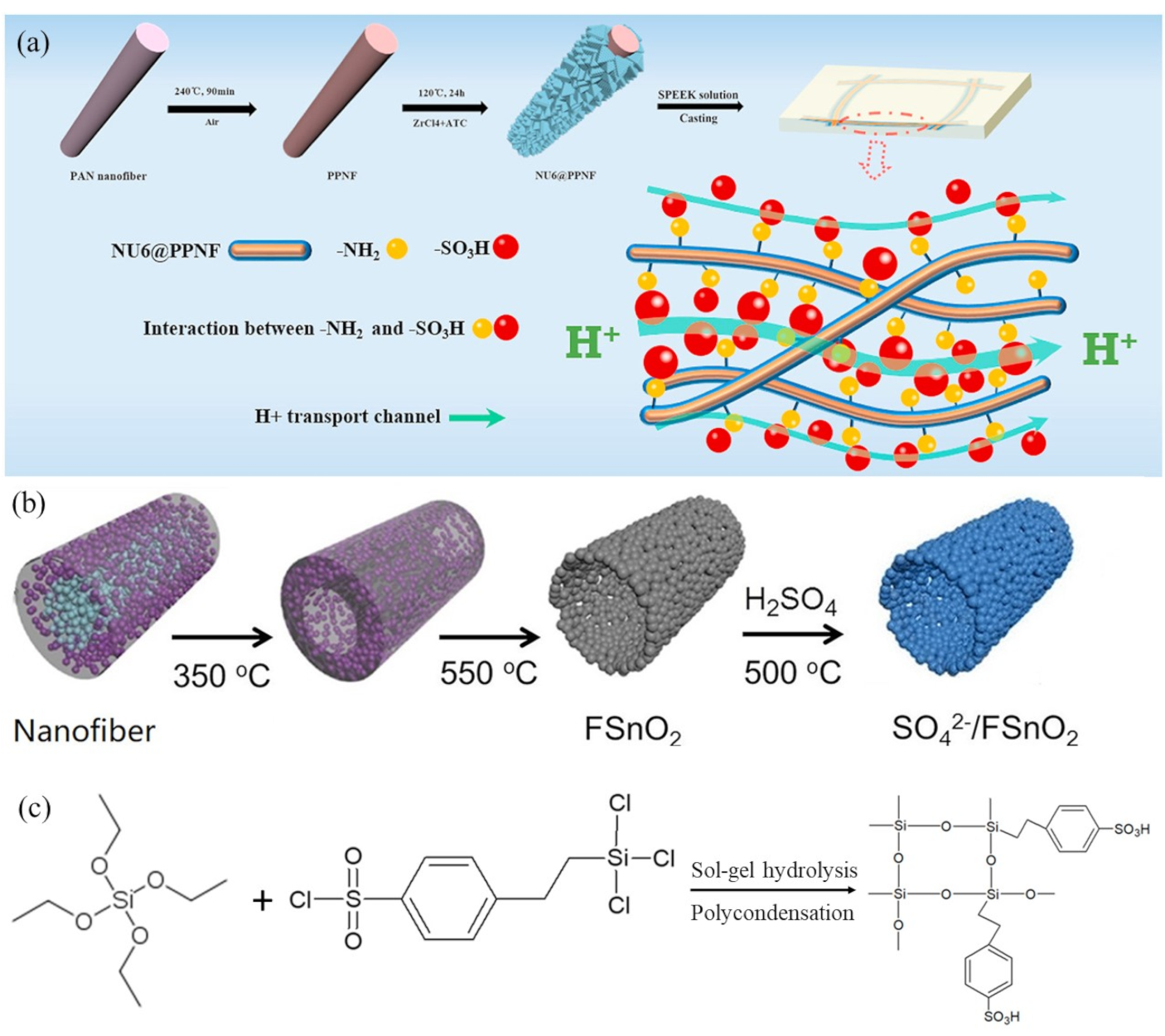
4.2. Nanofiber Composite Proton-Exchange Membranes with Functional Nanoparticles

In order to increase the water retention properties and proton conductivity of electrospun composite films, nanoparticles with functional groups have been added during membrane preparation. One example of this type of fuel cell membrane was developed by Choi et al. [17,18] where sulfonated polyhedral oligomeric silsesquioxane (sPOSS) with a high concentration of sulfonic acid ion-exchange groups was added to either a sulfonated polyarylene ether sulfone (sPAES) or PFSA electrospinning solution. A photo-crosslinkable polyurethane prepolymer liquid (Norland Optical Adhesive 63) was embedded between the ionomer fibers after electrospinning, followed by UV light exposure. A membrane composed of 2.1 mmol/g ion-exchange capacity sPAES with 40 wt% sPOSS had a conductivity of 94 mS/cm at 30 °C and 80% RH, which was 2.4-times higher than that of Nafion 212 under the same conditions. At 80 °C and 90% RH, the proton conductivity was 357 mS/cm and the equilibrium water swelling was 32%. Facile H+ transport in this membrane was due to the high IEC and water retention properties of the sPAES-sPOSS nanofibers, where, for example, the equilibrium adsorption of water vapor at 80% RH was 3.8-times higher than that of a commercial Nafion film.
Another example of this membrane morphology was reported by Zhu et al. [63] who fabricated membranes from nanofibers that were coated with functional metal-organic frameworks (MOFs). MOF NH2-UiO-66 (NU6) with -NH2 ligands was used in this study to modify pre-oxidized polyacrylonitrile nanofibers (PPNF) which were sandwiched between two dense layers of sulfonated poly(ether ether ketone) (SPEEK) to form a composite membrane. Figure 5a shows the fabrication process and the proton transport mechanism in the presence of -NH2 and -SO3 interactions. The amino groups of modified PPNF fibers (denoted as NU6@PPNF) formed acid-base pairs with the –SO3H fixed-charge groups of SPEEK. H+ could easily hop through continuous low energy barrier channels formed by these acid-base pairs. Thus, at 60 °C and 100% RH, the in-plane expansion and conductivity of a membrane with 1.3% NU6-PPNF/SPEEK fibers were 14.0% and 132.8 mS/cm, respectively.
Nanoparticles with multiple types of acid sites (Brönsted or Lewis type) can be used in the fabrication of nanofibers with a high concentration of strongly acidic proton carriers and enhanced hydrogen bonding for rapid proton transport. Chen, et al. [64] electrospun sulfated SnO2 hollow nanofibers through a single-spinneret from a PAN/PVP/SnCl2/DMF mixture. The resulting fiber mat, where PAN spontaneously migrated to the fiber core, was annealed in the presence of H2SO4 to produce sulfated SnO2. Figure 5b shows the fabrication process. Nanofibers were heated at 350 °C and then 550 °C to eliminate PAN and PVP. Hollow fibers containing sulfated SnO2 were obtained and added to a sulfonated poly(phthalazinone ether sulfone ketone) (SPPESK) membrane casting solution. The hydrogen bonding interactions at the interface between sulfated SnO2 and SPPESK promoted the formation of ion conducting channels in solution cast films. One membrane, denoted as SPPESK-SF-7.5, had excellent characteristics, with proton conductivity of 226.7 mS/cm at 80 °C and mechanical strength of 31.4 MPa (for a film in its hydrated form).
There have been numerous attempts at improving the low humidity and high temperature proton conductivity of Nafion by addition of hydrophilic silica particles. The rationale for this approach, that silica would increase water retention and thus improve proton conductivity at low relative humidity, was proven to be flawed. While silica increases the membrane water content, it also dilutes the charges in Nafion resulting in a drop in proton conductivity as compared to neat Nafion film [83]. The membrane/method of Choi et al. [56,57] discussed above, where sPOSS is added to electrospun fibers was one approach to address this problem. More recently, Dos Santos et al. [19] fabricated dual fiber PFSA/PVDF composite membranes with sulfonated silica, denoted as S-SiO2, formed in-situ from 2-(4-chlorosulfonylphenyl)ethyltrichlorosilane and tetraethyl orthosilicate via a sol-gel reaction before/during/after fiber electrospinning. The sol-gel chemical reaction is shown in Figure 5c. The sol-gel precursors were added to either PFSA or to PVDF. The proton conductivity of a membrane (PVDF fibers/PFSA matrix) made with sulfonated silica in PFSA matrix (Type A) was higher than that of a membrane where the sulfonated silica was in the reinforcing PVDF fibers (Type B). A Type-A membrane containing 65% PFSA with 15% sulfonated silica and 20% reinforcing PVDF fibers and an effective membrane IEC of 1.45 mmol/g had a proton conductivity of 210 mS/cm at 80 °C and 90% RH, which was similar to a neat 660 EW film with a comparable IEC, but the water swelling and mechanical strength of the nanofiber composite membrane were much improved, i.e., less water swelling (12% vs. 35% in liquid water 25 °C). A type-B membrane containing 65 wt.% PFSA and 20 wt.% reinforcing PVDF fibers with 15 wt.% sulfonated silica with an effective IEC of 1.42 mmol/g also exhibited low in-plane water swelling (12%), but its conductivity was quite low at only 59 mS/cm in liquid water at 20 °C.
A hydrophobic poly(vinylidene fluoride-co-trifluoroethylene) (P(VDF-TrFE)), which has a similar structure to PVDF, was examined as a new electrospinning carrier polymer for sulfonated silica. Mojarrad et al. [65] prepared nanofiber-based hybrid PEMs from sulfonated silica/PVDF and from sulfonated silica/P(VDF-TrFE) fibers, embedded in Nafion. Electrospun fiber mats of PVDF/S-SiO2 and of P(VDF-TrFE)/S-SiO2 were prepared and densified by hot-pressing at 110 °C under 2000 psi pressure, followed by Nafion impregnation. The final dense composite membrane with Nafion and P(VDF-TrFE)/S-SiO2 fibers had a proton conductivity of 102 mS/cm at 70 °C and 100% RH, which was higher than that in a membrane with Nafion and only PVDF/S-SiO2 fibers (43 mS/cm) and was also higher than a solution cast Nafion membrane with conductivity of 95 mS/cm.

5. Electrospun Anion-Exchange Membranes

Anion-exchange membranes (AEMs) contain fixed positively charged sites and negatively charged mobile counter-ions (anions). As compared with cation-exchange membranes, there are fewer studies on alkaline membranes (i.e., AEMs with mobile OH anions) for fuel cells, although in recent years, research on these types of membranes has accelerated greatly. Most AEMs exhibit poor stability in alkaline media as their degradation is induced by the strongly nucleophilic hydroxide ion, which can attack both the polymer backbone [84,85] and cationic fixed-charge groups [86].
Polysulfone is frequently used as the backbone polymer during the synthesis of alkaline membrane materials, largely due to its excellent mechanical strength and chemical stability, combined with its capability of forming flexible, thin films [87]. Polysulfone ionomers with quaternary ammonium or methyl imidazolium anion-exchange sites (henceforth abbreviated as QAPS and IMPS, respectively) have been extensively studied due to their ease of synthesis, i.e., the ability to vary the IEC of the final polymer. Both ionomer types can be obtained by chloromethylation of the base polysulfone polymer followed by soaked in an aqueous solution of trimethylamine (TMA), 1-methylimidazole or 1, 2-dimethylimidazole to convert the chloromethyl moieties to quaternary ammonium or methyl imidazolium fixed-charge sites. To achieve an acceptable OH conductivity for fuel cell applications, the IEC of QAPS or IMPS must be very high which leads to excessive swelling in water and the loss of mechanical properties. Consequently, these ionomers are excellent candidate materials for composite membranes using a dual fiber electrospinning approach.
The first electrospun composite AEM was reported by Pintauro’s research group in 2011 [66], which was followed by the work of Roddecha and co-workers [67]. The two groups independently prepared heterogeneous composite AEMs based on QAPS electrospun nanofibers, where the membranes were composed of OH conductive fibers embedded in an uncharged/inert polymer matrix. Such a structure led to a significant reduction of ionomer water uptake and to an enhancement of the mechanical properties of the membrane.
Roddecha et al. [67] electrospun QAPS solutions into nanofibers, which were then pressed, solvent welded to form an interconnected fiber mat, and then filled with polydimethylsiloxane (PDMS) to obtain a composite membrane. The IEC of the fibers was as high as 1.81 mmol/g and the resultant membranes had a conductivity of 69 mS/cm and a tensile strength of 4.9 MPa. Instead of the pore-filling approach, Park et al. [66] from Pintauro’s group co-electrospun chloromethylated polysulfone precursor and PPSU, then performed an amination step followed by exposure to chloroform and mechanical compression to obtain dense AEMs where an interconnected network of QAPS fibers was embedded in an uncharged PPSU matrix. Membranes with 37 wt.% PPSU had very good characteristics: an IEC of 1.27–1.56 mmol/g, a OH conductivity of 40 mS/cm, water swelling of 93%, and a tensile strength (22.3 MPa) which was much higher than that of Roddecha’s membranes (4.9 MPa).
To further reduce the water swelling of a dual-fiber AEM, Park et al. [68] crosslinked electrospun ionomer fibers in a composite membrane. Before solvent exposure and compression, nanofibers with chloromethyl groups were briefly soaked in a solution of diamine crosslinker and then left in trimethylamine (TMA) solution to fully quaternize the remaining chloromethyl sites. The crosslinked ionomer fibers had an IEC of 1.52–2.05 mmol/g and were completely insoluble in water. The resultant AEMs showed excellent OH ion conductivity in water (65 mS/cm). In chemical stability tests, the conductivity ofa composite membranes in the OH-form did not change over 5 days of immersion in 50 °C water, but there was some loss in conductivity during a 70 °C water soak experiment.
To improve the alkaline stability of AEMs, Park et al. incorporated imidazolium ion-exchange sites into their nanofiber composite membranes [69]. Compared with quaternary ammonium fixed cations, imidazolium cations have shown greater alkaline stability due to their cyclic-conjugated structure. They also have excellent thermal stability and high ionic conductivity, which make them one of the most suitable groups for the synthesis of OH conductive ionomers. In his work, Park et al. replaced diamine crosslinker with diol crosslinked in dual-fiber AEMs. A membrane containing 35 wt.% poly(phenyl sulfone) and 65 wt.% crosslinked polysulfone fibers with 1, 2-dimethylimidazolium fixed charge sites and 8% crosslinking had a room temperature OH ion conductivity of 49 mS/cm, a gravimetric swelling of 96%, and an ultimate stress of 16 MPa. Its chemical stability was moderately good with only 20% loss of conductivity after 3 days in 1.0 M KOH at 50 °C.
Poly(phenylene oxide) (PPO) ammonium derivatives showed a slower degradation rate and thus a longer life in strong alkaline media, so they were also considered good candidates for AEM. Park et al. [70] prepared and evaluated dual fiber electrospun composite membranes with PPSU and brominated PPO fibers, where the latter were crosslinked and aminated with trimethylamine or methylimidazole. Figure 6a shows the crosslinking reaction of brominated PPO with hexamethylenediamine. After crosslinking, the remaining bromide sites were converted to benzyl trimethylammonium or 1,2-dimethylimidazolium fixed charges. The degree of crosslinking and the ratio of uncharged PPSU to functionalized poly(phenylene oxide) were varied to give an effective IEC in the 1.2–2.8 mmol/g range. A membrane with benzyl trimethylammonium groups, 15% crosslinks and 50 wt.% uncharged PPSU matrix showed a high hydroxide ion conductivity (66 mS/cm in water at 23 °C), reasonable water swelling (96%), good mechanical strength (15 MPa in the hydrated state), and good chemical stability in 1.0 M KOH at 60 °C. Initial hydrogen/oxygen fuel cell testing with a 40-μm thick membrane gave a peak power density of 320 mW/cm2.
In order to achieve better compatibility of cationic fibers and uncharged matrix, Gong et al. [73] prepared membranes using the pore-filling method, where electrospun fibers and the interfiber void filler were made from the same ionomer—an imidazolium-functionalized polysulfone (IMPSF). The researchers utilized solubility difference of IMPSF in different solvents, where DMF was used as the electrospinning solvent and hot glycol/water mixture was used to prepare the pore-filling solution. The conductivity of a compositeIMPS membrane (IEC 1.78 mmol/g) equilibrated with room temperature water, was 38.4 mS/cm, which was higher than that of a solution cast film (31.8 mS/cm). The water swelling was reduced from 62.7% to 40.6%, and the tensile strength was increased from 14.8 MPa to 21.4 MPa, as compared to the solution cast membrane. A similar approach was employed by Watanabe et al. [71] who prepared composite membranes using a single-type of alkaline ionomer, quaternized poly(arylene ether sulfone) (QPAES), for both electrospinning and pore impregnation. Figure 6b showed the fabrication process for making a pore-filled composite membrane. Ionomer was first electrospun into a fiber mat and then impregnated using the same ionomer solution. The conductivity of the composite membrane (with an IEC of 1.51 mmol/g) in water at 30 °C was 83 mS/cm and the water uptake was 104%. In comparison, a solution cast membrane had half the conductivity. In another study, Wang et al. [74] prepared AEMs from electrospun and crosslinked high IEC QPAES impregnated with a lower IEC QPAES. A fiber mat from QPAES-90/10 (10 mol.% quaternary amine groups and 90 mol.% residual tertiary amine groups) was first soaked in a solution of p-xylylene dichloride in dichloromethane to crosslink the ionomer. Then the mat was impregnated with a DMAc solution of QPAES-70/30 containing p-xylylene dichloride. A flexible membrane was obtained after solvent evaporation and heat treatment (80 °C for 12 h). A composite membrane with an IEC of 3.31 mmol/g had a hydroxide ion conductivity of 66 mS/cm and a water uptake of 23% at 20 °C, with excellent mechanical characteristics (a tensile strength of 54.5 MPa and an elongation at break of 22.5% for films equilibrated in 50% RH air).
In an effort to improve the alkaline stability of AEMs, fixed charge groups other than quaternary ammonium and imidazolium have also been examined in electrospun AEMs. Due to their strongly basic character, guanidines are considered superbases and they yield a higher concentration of mobile OH ions as compared to quaternary ammonium hydroxides. Wang et al. [75] electrospun poly(aryl ether sulfone) nanofibers with hexaalkyl guanidinium groups side chains (PES-G-OH) and impregnated the resultant scaffold with an aqueous solution of vinylbenzyl trimethylammonium chloride and N,N′-methylene bisacrylamide crosslinker. After polymerization, water evaporation and conversion of the chloride counterions to OH, composite alkaline membranes with good characteristics were obtained. For example, when the ratio of vinylbenzyl trimethylammonium chloride and N,N′-methylene bisacrylamide was 16/1 wt/wt, the resultant membrane had a water uptake of 20% and a hydroxide ion conductivity of 0.046 S/cm at 20 °C, which increased to 0.092 S/cm at 70 °C. The conductivity of the composite membrane was higher than that of a solution cast PES-G-OH film, over a wide temperature range. Thermogravimetric data revealed improved thermal stability of the composite membrane due to the presence of the reinforcing matrix.
An interesting approach to improving the conductivity of electrospun composite AEMs was demonstrated by Gong et al. [72], who utilized the tendency of carbon nanotubes (MWCNTs) to orient in an electric field. Electrospun fiber mats were prepared from imidazolium-functionalized polysulfone, which also contained imidazolium-fiunctionalized MWCNTs. The mats were exposed to DMF vapor at 60 °C for 10 min to weld intersecting fibers and then compacted at 80 °C and 3 MPa for 15 min. Interfiber voids were filled with imidazolium-functionalized polysulfone. Figure 6c shows that MWCNTs were able to align along the axis of electrospun nanofibers, thereby solving the problem of MWCNT agglomeration in solution cast membranes. Imidazolium functional groups on MWCNTs and in the polysulfone matrix interacted with one another and contributed to forming better ion transport channels (shown in Figure 6c). The maximum hydroxide conductivity observed at a MWCNT additive content of 0.4 wt.% was 67.5 mS/cm at 30 °C, which was 3.3-times higher than that of a solution-cast neat ionomer membrane. A fuel cell test at 60 °C generated a maximum power density of 102.5 mW/cm2, which was 12-times higher than that with a solution cast film of imidazolium-functionalized polysulfone.

6. Summary and Future Challenges

There are many approaches to obtain the proper balance of conductivity, durability, and mechanical properties of fuel cell proton-exchange membranes (PEMs) and anion-exchange membranes (AEMs). A composite ion-exchange membrane (IEM) with one or more nanofiber components is one such approach that provides a robust platform to address this balance. In this review, various fuel cell IEMs are presented that utilize nanofiber electrospinning-based fabrication. In most open literature studies, a nanofiber morphology significantly improves the mechanical properties and dimensional stability of the final membrane without sacrificing ion conductivity. In some cases, fiber mats electrospun from uncharged polymers are used as a reinforcement that is embedded in an ionomer matrix. In others, an electrospun mat of interconnected ionomer nanofibers is used as the ion-conducting network, where uncharged polymer surrounds the nanofibers to limit ionomer swelling in water and to improve the wet and dry mechanical properties of the composite membrane. Membranes are fabricated by either embedding polymer in a pre-formed electrospun nanofiber or by simultaneously electrospinning both the ionomer and reinforcing polymers followed by a pore closure step in the resulting dual fiber mat. Dual fiber electrospinning enables compatibilization of highly dissimilar polymers, where after mat compaction (pore closure), a blended polymer film can be fabricated that could not have been made by conventional solution casting. Additional levels of structural sophistication can be easily added to nanofiber-based PEMs and AEMs. For example, one can use dual fiber electrospinning of charged and uncharged polymer nanofibers to create membranes with a layered morphology (high and low weight fractions of reinforcing polymer) or a gradient composition (ionomer to reinforcing polymer) in the membrane thickness direction. Similarly, one can add charged inorganic particles to electrospun fibers to enhance ion conductivity, e.g., by the addition of sulfonated POSS to Nafion fibers.
At first glance, polymer nanofiber electrospinning may appear to be a complicated and expensive membrane fabrication method, but there are presently available commercial electrospinners for large-scale manufacturing (made by Elmarco s.r.o., Liberec, Czechia and Inovenso Ltd., Istanbul, Turkey for example). Commercial products, e.g., in the areas of filtration and biomedicine, are being produced today by nanofiber electrospinning, and the cost of manufacturing membranes with electrospun nanofibers is quite reasonable. A 2018 study by Strategic Analysis, Inc. estimated the cost of manufacturing PFSA-based nanofiber composite fuel cell membranes by: (a) PFSA ionomer impregnation into a pre-formed electrospun mat of poly(phenyl sulfone) (PPSU) reinforcing fibers and (b) dual fiber (PFSA and PPSU) electrospinning followed by interfiber pore closure [88]. As expected, the analysis showed that the total membrane manufacturing cost (the sum of raw material and fabrication costs) decreased with increased production rate (see Figure 7, where systems refers to 80 kW fuel cell stacks). Figure 7 also shows that the two membranes with electrospun fiber components have lower manufacturing costs versus that of a W. L. Gore-type (Newark, DE, USA) expanded-Teflon® (ePTFE)-reinforced PFSA film. This study found that the Gore-type membrane was dominated by materials cost (primarily the ePTFE support material), whereas the manufacturing costs were dominant for the two electrospun films.
At present, electrospun ion-exchange membranes represent a minority of all fuel cell PEMs and AEMs under investigation. The widespread commercialization of nanofiber-based membranes will depend on how easy it will be to incorporate large-scale electrospinning equipment into traditional roll-to-roll membrane fabrication lines. Nevertheless, the prospects for developing new high-performance nanofiber composite membranes are very encouraging, which no doubt will contribute to the widespread manufacturing and deployment of low-cost and high performance fuel cells. While scale-up and cost issues will be resolved by industry adoption of electrospinning, there are numerous avenues for further fundamental research regarding new nanofiber PEM and AEM morphologies. Prior work focused on two-component nanofiber composite films, but multi-fiber electrospun membranes may better address durability/properties issues. A membrane with three or more different fibers, where each fiber performs a different function has yet to be investigated, e.g., a multicomponent nanofiber mat embedded in an inert matrix where one fiber provides mechanical properties, another provide ion conduction at low relative humidity, and a third fiber conducts at high humidity. An improved understanding and better control of the fiber/matrix interfacial morphology and the possible creation of ion transmission channels at the surface of nanofibers is certainly a research area worthy of pursuit. Other challenges for the electrospinning community include: (a) The creation of PEMs and AEMS where most/all of the ion-conducting fibers are oriented perpendicular to the membrane surface to eliminate tortuosity effects on ion migration; (b) spinning fibers with two or more polymers or a polymer/particle mixture where the radial distribution of fiber components is controlled; (c) spinning nanofibers with permanently aligned polymer chains in the axial fiber direction, where such alignment leads to enhanced ion-conductivity; and (d) the exploitation of core-shell nanofiber structures to create new composite membranes where, for example, ionomer is located in the fiber shell and uncharged reinforcing polymer is in the core.

Author Contributions

Conceptualization, Z.S., R.W. and P.P.; investigation, Z.S., R.W. and P.P.; writing—original draft preparation, Z.S.; writing—review and editing, R.W. and P.P.; supervision, R.W. and P.P.; funding acquisition, P.P. and R.W. All authors have read and agreed to the published version of the manuscript.

Funding

This work was funded in part by grants from the U.S. Department of Energy, Office of Energy Efficiency and Renewable Energy, contract Nos. DE-EE0007653 and DE-EE0008435.

Conflicts of Interest

The authors declare no conflict of interest.

Abbreviations

AEManion-exchange membrane
cPPSAcrosslinkable poly(phenylenesulfonic acid)
EWequivalent weight (IEC with units of mol/g = 1/EW)
IEMion-exchange membrane
IMPSimidazolium polysulfone
MWCNTmulti-walled carbon nanotubes
NOA 63Norland Optical Adhesive 63
NU6NH2-UiO-66
PAIpolyamidimide
PDMSpolydimethylsiloxane
PEMproton-exchange membrane
PES-G-OHpoly(aryl ether sulfone) with hexaalkyl guanidinium group side chains
PFSAperfluorosulfonic acid
PPNFpre-oxidized polyacrylonitrile nanofibers
PPSUpoly(phenyl sulfone)
PSUTtriazole functionalized polysulfone
PTFEpolytetrafluoroethylene
PVDFpoly(vinylidene fluoride)
P(VDF-TrFE)poly(vinylidene fluoride-co-trifluoroethylene)
QAPSquaternary ammonium polysulfone
QPAESquaternized poly(arylene ether sulfone)
QPPOquaternized poly(phenylene oxide)
sPAESsulfonated poly(arylene ether sulfone)
SPEEKsulfonated poly(ether ketone)
sPOSSsulfonated poly(hedral oligomeric silsesquioxane)
SPPESKsulfonated poly(phthalazinone ether sulfone ketone)
S-SiO2sulfonated silica
VBTCvinylbenzyltrimethylammonium chloride

References

  1. Zhang, H.; Sun, C. Cost-effective iron-based aqueous redox flow batteries for large-scale energy storage application: A review. J. Power Sources 2021, 493, 229445. [Google Scholar] [CrossRef]
  2. Staffell, I.; Scamman, D.; Velazquez Abad, A.; Balcombe, P.; Dodds, P.E.; Ekins, P.; Shah, N.; Ward, K.R. The Role of Hydrogen and Fuel Cells in the Global Energy System. Energy Environ. Sci. 2019, 12, 463–491. [Google Scholar] [CrossRef] [Green Version]
  3. Schlick, S.; Wiley, J. The Chemistry of Membranes Used in Fuel Cells: Degradation and Stabilization; John Wiley & Sons: Hoboken, NJ, USA, 2018. [Google Scholar]
  4. Williams, M.; Krist, K.; Garland, N. Electrochemical Society. In Fuel Cell Seminar 2008; Electrochemical Society: Pennington, NJ, USA, 2009. [Google Scholar]
  5. Wycisk, R.; Pintauro, P.N.; Park, J.W. New Developments in Proton Conducting Membranes for Fuel Cells. Curr. Opin. Chem. Eng. 2014, 4, 71–78. [Google Scholar] [CrossRef]
  6. Gloukhovski, R.; Freger, V.; Tsur, Y. Understanding Methods of Preparation and Characterization of Pore-Filling Polymer Composites for Proton Exchange Membranes: A Beginner’s Guide. Rev. Chem. Eng. 2017, 34, 455–479. [Google Scholar] [CrossRef]
  7. Kusoglu, A.; Weber, A.Z. New Insights into Perfluorinated Sulfonic-Acid Ionomers. Chem. Rev. 2017, 117, 987–1104. [Google Scholar] [CrossRef] [PubMed]
  8. Itoh, T. Hyperbranched Polymer Electrolytes for High Temperature Fuel Cells; Elsevier Ltd.: Amsterdam, The Netherlands, 2010. [Google Scholar]
  9. Feng, M.; Qu, R.; Wei, Z.; Wang, L.; Sun, P.; Wang, Z. Characterization of the Thermolysis Products of Nafion Membrane: A Potential Source of Perfluorinated Compounds in the Environment. Sci. Rep. 2015, 5, 9859. [Google Scholar] [CrossRef]
  10. Li, J.; Pan, M.; Tang, H. Understanding Short-Side-Chain Perfluorinated Sulfonic Acid and Its Application for High Temperature Polymer Electrolyte Membrane Fuel Cells. RSC Adv. 2014, 4, 3944–3965. [Google Scholar] [CrossRef]
  11. Sun, C.; Negro, E.; Vezzù, K.; Pagot, G.; Cavinato, G.; Nale, A.; Herve Bang, Y.; Di Noto, V. Hybrid Inorganic-Organic Proton-Conducting Membranes Based on SPEEK Doped with WO3 Nanoparticles for Application in Vanadium Redox Flow Batteries. Electrochim. Acta 2019, 309, 311–325. [Google Scholar] [CrossRef]
  12. Bai, H.; Ho, W.S.W. New Sulfonated Polybenzimidazole (SPBI) Copolymer-Based Proton-Exchange Membranes for Fuel Cells. J. Taiwan Inst. Chem. Eng. 2009, 40, 260–267. [Google Scholar] [CrossRef]
  13. Woo, Y.; Oh, S.Y.; Kang, Y.S.; Jung, B. Synthesis and Characterization of Sulfonated Polyimide Membranes for Direct Methanol Fuel Cell. J. Membr. Sci. 2003, 220, 31–45. [Google Scholar] [CrossRef]
  14. Devrim, Y.; Erkan, S.; Baç, N.; Eroğlu, I. Preparation and Characterization of Sulfonated Polysulfone/Titanium Dioxide Composite Membranes for Proton Exchange Membrane Fuel Cells. Int. J. Hydrog. Energy 2009, 34, 3467–3475. [Google Scholar] [CrossRef]
  15. Li, W.; Jiang, J.; An, H.; Dong, S.; Yue, Z.; Qian, H.; Yang, H. Self-Cross-Linked Sulfonated Poly(Ether Ether Ketone) with Pendant Sulfoalkoxy Groups for Proton Exchange Membrane Fuel Cells. ACS Appl. Energy Mater. 2021, 4, 2732–2740. [Google Scholar] [CrossRef]
  16. Si, K.; Wycisk, R.; Dong, D.; Cooper, K.; Rodgers, M.; Brooker, P.; Slattery, D.; Litt, M. Rigid-Rod Poly(Phenylenesulfonic Acid) Proton Exchange Membranes with Cross-Linkable Biphenyl Groups for Fuel Cell Applications. Macromolecules 2012, 46, 422–433. [Google Scholar] [CrossRef]
  17. Choi, J.; Lee, K.M.; Wycisk, R.; Pintauro, P.N.; Mather, P.T. Sulfonated Polysulfone/POSS Nanofiber Composite Membranes for PEM Fuel Cells. J. Electrochem. Soc. 2010, 157, B914. [Google Scholar] [CrossRef]
  18. Choi, J.; Wycisk, R.; Zhang, W.; Pintauro, P.N.; Lee, K.M.; Mather, P.T. High Conductivity Perfluorosulfonic Acid Nanofiber Composite Fuel-Cell Membranes. ChemSusChem 2010, 3, 1245–1248. [Google Scholar] [CrossRef] [PubMed]
  19. Santos, L.D.; Powers, D.; Wycisk, R.; Pintauro, P.N. Electrospun Hybrid Perfluorosulfonic Acid/Sulfonated Silica Composite Membranes. Membranes 2020, 10, 250. [Google Scholar] [CrossRef]
  20. Dekel, D.R. Review of Cell Performance in Anion Exchange Membrane Fuel Cells. J. Power Sources 2018, 375, 158–169. [Google Scholar] [CrossRef]
  21. Hossain, M.M.; Yang, Z.; Wu, L.; Liang, X.; Xu, T. Introducing a New Generation of Anion Conducting Membrane Using Swelling Induced Fabrication of Covalent Methanol Barrier Layer. J. Membr. Sci. 2021, 620, 118840. [Google Scholar] [CrossRef]
  22. Shen, C.; Wycisk, R.; Pintauro, P.N. High Performance Electrospun Bipolar Membrane with a 3D Junction. Energy Environ. Sci. 2017, 10, 1435–1442. [Google Scholar] [CrossRef]
  23. Lu, H.; Wang, L.; Wycisk, R.; Pintauro, P.N.; Lin, S. Quantifying the Kinetics-Energetics Performance Tradeoff in Bipolar Membrane Electrodialysis. J. Membr. Sci. 2020, 612, 118279. [Google Scholar] [CrossRef]
  24. Chempath, S.; Einsla, B.R.; Pratt, L.R.; Macomber, C.S.; Boncella, J.M.; Rau, J.A.; Pivovar, B.S. Mechanism of Tetraalkylammonium Headgroup Degradation in Alkaline Fuel Cell Membranes. J. Phys. Chem. C 2008, 112, 3179–3182. [Google Scholar] [CrossRef]
  25. Miyanishi, S.; Yamaguchi, T. Analysis of the Degradation Mechanism of the Polyarylene Ether Anion-Exchange Membrane for Alkaline Fuel Cell and Water-Splitting Cell Applications. New J. Chem. 2017, 41, 8036–8044. [Google Scholar] [CrossRef]
  26. Kumari, M.; Douglin, J.C.; Dekel, D.R. Crosslinked Quaternary Phosphonium-Functionalized Poly(Ether Ether Ketone) Polymer-Based Anion-Exchange Membranes. J. Membr. Sci. 2021, 626, 119167. [Google Scholar] [CrossRef]
  27. Yadav, V.; Rajput, A.; Sharma, P.P.; Jha, P.K.; Kulshrestha, V. Polyetherimide Based Anion Exchange Membranes for Alkaline Fuel Cell: Better Ion Transport Properties and Stability. Colloids Surf. A Physicochem. Eng. Asp. 2020, 588, 124348. [Google Scholar] [CrossRef]
  28. Das, G.; Park, B.J.; Kim, J.; Kang, D.; Yoon, H.H. Quaternized Cellulose and Graphene Oxide Crosslinked Polyphenylene Oxide Based Anion Exchange Membrane. Sci. Rep. 2019, 9, 9572. [Google Scholar] [CrossRef] [PubMed]
  29. Cotanda, P.; Sudre, G.; Modestino, M.A.; Chen, X.C.; Balsara, N.P. High Anion Conductivity and Low Water Uptake of Phosphonium Containing Diblock Copolymer Membranes. Macromolecules 2014, 47, 7540–7547. [Google Scholar] [CrossRef] [Green Version]
  30. Sherazi, T.A.; Zahoor, S.; Raza, R.; Shaikh, A.J.; Naqvi, S.A.R.; Abbas, G.; Khan, Y.; Li, S. Guanidine Functionalized Radiation Induced Grafted Anion-Exchange Membranes for Solid Alkaline Fuel Cells. Int. J. Hydrog. Energy 2015, 40, 786–796. [Google Scholar] [CrossRef]
  31. Mondal, R.; Pal, S.; Chatterjee, U. Alkylated Imidazole Moieties in a Cross-Linked Anion Exchange Membrane Facilitate Acid Recovery with High Purity. ACS Appl. Polym. Mater. 2021, 3, 1544–1554. [Google Scholar] [CrossRef]
  32. Yoshimura, K.; Zhao, Y.; Hasegawa, S.; Hiroki, A.; Kishiyama, Y.; Shishitani, H.; Yamaguchi, S.; Tanaka, H.; Koizumi, S.; Appavou, M.-S.; et al. Imidazolium-Based Anion Exchange Membranes for Alkaline Anion Fuel Cells: (2) Elucidation of the Ionic Structure and Its Impact on Conducting Properties. Soft Matter 2017, 13, 8463–8473. [Google Scholar] [CrossRef] [PubMed]
  33. Zha, Y.; Disabb-Miller, M.L.; Johnson, Z.D.; Hickner, M.A.; Tew, G.N. Metal-Cation-Based Anion Exchange Membranes. J. Am. Chem. Soc. 2012, 134, 4493–4496. [Google Scholar] [CrossRef] [PubMed]
  34. Zeng, L.; Zhao, T.S.; An, L.; Zhao, G.; Yan, X.H. A High-Performance Sandwiched-Porous Polybenzimidazole Membrane with Enhanced Alkaline Retention for Anion Exchange Membrane Fuel Cells. Energy Environ. Sci. 2015, 8, 2768–2774. [Google Scholar] [CrossRef]
  35. Henkensmeier, D.; Najibah, M.; Harms, C.; Žitka, J.; Hnát, J.; Bouzek, K. Overview: State-of-the Art Commercial Membranes for Anion Exchange Membrane Water Electrolysis. J. Electrochem. Energy Convers. Storage 2020, 18, 024001. [Google Scholar] [CrossRef]
  36. Varcoe, J.R.; Atanassov, P.; Dekel, D.R.; Herring, A.M.; Hickner, M.A.; Kohl, P.A.; Kucernak, A.R.; Mustain, W.E.; Nijmeijer, K.; Scott, K.; et al. Anion-Exchange Membranes in Electrochemical Energy Systems. Energy Environ. Sci. 2014, 7, 3135–3191. [Google Scholar] [CrossRef] [Green Version]
  37. Amel, A.; Smedley, S.B.; Dekel, D.R.; Hickner, M.A.; Ein-Eli, Y. Characterization and Chemical Stability of Anion Exchange Membranes Cross-Linked with Polar Electron-Donating Linkers. J. Electrochem. Soc. 2015, 162, F1047–F1055. [Google Scholar] [CrossRef]
  38. Hagesteijn, K.F.L.; Jiang, S.; Ladewig, B.P. A Review of the Synthesis and Characterization of Anion Exchange Membranes. J. Mater. Sci. 2018, 53, 11131–11150. [Google Scholar] [CrossRef] [Green Version]
  39. Dekel, D.R.; Amar, M.; Willdorf, S.; Kosa, M.; Dhara, S.; Diesendruck, C.E. Effect of Water on the Stability of Quaternary Ammonium Groups for Anion Exchange Membrane Fuel Cell Applications. Chem. Mater. 2017, 29, 4425–4431. [Google Scholar] [CrossRef] [Green Version]
  40. Smith, R.A.; Withers, M.S. Coextruded Multilayer Cation Exchange Membranes. U.S. Patent 4,437,952, 20 March 1984. [Google Scholar]
  41. Mbarek, S.; El Kissi, N.; Baccouch, Z.; Iojoiu, C. Extrusion of Nafion and Aquivion Membranes: Environmentally Friendly Procedure and Good Conductivities. Polym. Bull. 2018, 76, 1151–1166. [Google Scholar] [CrossRef]
  42. Zheng, G.; Jiang, J.; Wang, X.; Li, W.; Liu, J.; Fu, G.; Lin, L. Nanofiber Membranes by Multi-Jet Electrospinning Arranged as Arc-Array with Sheath Gas for Electrodialysis Applications. Mater. Des. 2020, 189, 108504. [Google Scholar] [CrossRef]
  43. Doshi, J.; Reneker, D.H. Electrospinning Process and Applications of Electrospun Fibers. J. Electrost. 1995, 35, 151–160. [Google Scholar] [CrossRef]
  44. Niu, H.; Zhou, H.; Wang, H. Electrospinning: An Advanced Nanofiber Production Technology. In Energy Harvesting Properties of Electrospun Nanofibers; IOP Publishing: Bristol, UK, 2019. [Google Scholar]
  45. Hu, J.; Wang, X.; Ding, B.; Lin, J.; Yu, J.; Sun, G. One-Step Electro-Spinning/Netting Technique for Controllably Preparing Polyurethane Nano-Fiber/Net. Macromol. Rapid Commun. 2011, 32, 1729–1734. [Google Scholar] [CrossRef]
  46. Higashi, S.; Hirai, T.; Matsubara, M.; Yoshida, H.; Beniya, A. Dynamic Viscosity Recovery of Electrospinning Solution for Stabilizing Elongated Ultrafine Polymer Nanofiber by TEMPO-CNF. Sci. Rep. 2020, 10, 13427. [Google Scholar] [CrossRef]
  47. Ramakrishna, S.; Fujihara, K.; Teo, W.-E.; Yong, T.; Ma, Z.; Ramaseshan, R. Electrospun Nanofibers: Solving Global Issues. Mater. Today 2006, 9, 40–50. [Google Scholar] [CrossRef]
  48. Cheng, G.; Li, Z.; Ren, S.; Han, D.; Xiao, M.; Wang, S.; Meng, Y. A Robust Composite Proton Exchange Membrane of Sulfonated Poly (Fluorenyl Ether Ketone) with an Electrospun Polyimide Mat for Direct Methanol Fuel Cells Application. Polymers 2021, 13, 523. [Google Scholar] [CrossRef]
  49. Cui, J.; Lu, T.; Li, F.; Wang, Y.; Lei, J.; Ma, W.; Zou, Y.; Huang, C. Flexible and Transparent Composite Nanofibre Membrane That Was Fabricated via a “Green” Electrospinning Method for Efficient Particulate Matter 2.5 Capture. J. Colloid Interface Sci. 2021, 582, 506–514. [Google Scholar] [CrossRef] [PubMed]
  50. Eivazi Zadeh, Z.; Solouk, A.; Shafieian, M.; Haghbin Nazarpak, M. Electrospun Polyurethane/Carbon Nanotube Composites with Different Amounts of Carbon Nanotubes and Almost the Same Fiber Diameter for Biomedical Applications. Mater. Sci.Eng. C 2021, 118, 111403. [Google Scholar] [CrossRef] [PubMed]
  51. Zhou, W.; Gong, X.; Li, Y.; Si, Y.; Zhang, S.; Yu, J.; Ding, B. Environmentally Friendly Waterborne Polyurethane Nanofibrous Membranes by Emulsion Electrospinning for Waterproof and Breathable Textiles. Chem. Eng. J. 2022, 427, 130925. [Google Scholar] [CrossRef]
  52. Huang, J.; Hao, Y.; Zhao, M.; Li, W.; Huang, F.; Wei, Q. All-Fiber-Structured Triboelectric Nanogenerator via One-Pot Electrospinning for Self-Powered Wearable Sensors. ACS Appl. Mater. Interfaces 2021, 13, 24774–24784. [Google Scholar] [CrossRef] [PubMed]
  53. Slack, J.J.; Brodt, M.; Cullen, D.A.; Reeves, K.S.; More, K.L.; Pintauro, P.N. Impact of Polyvinylidene Fluoride on Nanofiber Cathode Structure and Durability in Proton Exchange Membrane Fuel Cells. J. Electrochem. Soc. 2020, 167, 054517. [Google Scholar] [CrossRef]
  54. Desai, F.; Seyedhassantehrani, N.; Shagar, M.; Gu, S.; Asmatulu, R. Preparation and Characterization of KOH-Treated Electrospun Nanofiber Mats as Electrodes for Iron-Based Redox-Flow Batteries. J. Energy Storage 2020, 27, 101053. [Google Scholar] [CrossRef]
  55. Powers, D.; Wycisk, R.; Pintauro, P.N. Electrospun Tri-Layer Membranes for H2/Air Fuel Cells. J. Membr. Sci. 2019, 573, 143. [Google Scholar] [CrossRef]
  56. Choi, J.; Lee, K.M.; Wycisk, R.; Pintauro, P.N.; Mather, P.T. Nanofiber Network Ion-Exchange Membranes. Macromolecules 2008, 41, 4569–4572. [Google Scholar] [CrossRef]
  57. Choi, J.; Lee, K.M.; Wycisk, R.; Pintauro, P.N.; Mather, P.T. Nanofiber Composite Membranes with Low Equivalent Weight Perfluorosulfonic Acid Polymers. J. Mater. Chem. 2010, 20, 6282. [Google Scholar] [CrossRef]
  58. Ballengee, J.B.; Pintauro, P.N. Preparation of Nanofiber Composite Proton-Exchange Membranes from Dual Fiber Electrospun Mats. J. Membr. Sci. 2013, 442, 187–195. [Google Scholar] [CrossRef]
  59. Ballengee, J.B.; Haugen, G.M.; Hamrock, S.J.; Pintauro, P.N. Properties and Fuel Cell Performance of a Nanofiber Composite Membrane with 660 Equivalent Weight Perfluorosulfonic Acid. J. Electrochem. Soc. 2013, 160, F429–F435. [Google Scholar] [CrossRef]
  60. Sood, R.; Giancola, S.; Donnadio, A.; Zatoń, M.; Donzel, N.; Rozière, J.; Jones, D.J.; Cavaliere, S. Active Electrospun Nanofibers as an Effective Reinforcement for Highly Conducting and Durable Proton Exchange Membranes. J. Membr. Sci. 2021, 622, 119037. [Google Scholar] [CrossRef]
  61. Park, J.W.; Wycisk, R.; Pintauro, P.N. Nafion/PVDF Nanofiber Composite Membranes for Regenerative Hydrogen/Bromine Fuel Cells. J. Membr. Sci. 2015, 490, 103–112. [Google Scholar] [CrossRef] [Green Version]
  62. Hossain, M.; Shang, Z.; Wycisk, R.; Pintauro, P.N. Pore-Filled PEMs from Poly(Phenylene Sulfonic Acid)S and Electrospun Poly(Phenylene Sulfone) Fiber Mats. ECS Trans. 2020, 98, 367–373. [Google Scholar] [CrossRef]
  63. Zhu, B.; Sui, Y.; Wei, P.; Wen, J.; Cao, H.; Cong, C.; Meng, X.; Zhou, Q. NH2-UiO-66 Coated Fibers to Balance the Excellent Proton Conduction Efficiency and Significant Dimensional Stability of Proton Exchange Membrane. J. Membr. Sci. 2021, 628, 119214. [Google Scholar] [CrossRef]
  64. Chen, W.; Chen, M.; Zhen, D.; Li, T.; Wu, X.; Tang, S.; Wan, L.; Zhang, S.; He, G. SO42‒/SnO2 Solid Superacid Granular Stacked One-Dimensional Hollow Nanofiber for a Highly Conductive Proton-Exchange Membrane. ACS Appl. Mater. Interfaces 2020, 12, 40740–40748. [Google Scholar] [CrossRef]
  65. Mojarrad, R.N.; Iskandarani, B.; Taşdemir, A.; Yürüm, A.; Gürsel, S.A.; Kaplan, B.Y. Nanofiber Based Hybrid Sulfonated Silica/P(VDF-TrFE) Membranes for PEM Fuel Cells. Int. J. Hydrog. Energy 2021, 46, 13583–13593. [Google Scholar] [CrossRef]
  66. Park, A.M.; Pintauro, P.N. Alkaline Fuel Cell Membranes from Electrospun Fiber Mats. Electrochem. Solid-State Lett. 2012, 15, B27. [Google Scholar] [CrossRef]
  67. Roddecha, S.; Dong, Z.; Wu, Y.; Anthamatten, M. Mechanical Properties and Ionic Conductivity of Electrospun Quaternary Ammonium Ionomers. J. Membr. Sci. 2012, 389, 478–485. [Google Scholar] [CrossRef]
  68. Park, A.M.; Turley, F.E.; Wycisk, R.J.; Pintauro, P.N. Electrospun and Cross-Linked Nanofiber Composite Anion Exchange Membranes. Macromolecules 2013, 47, 227–235. [Google Scholar] [CrossRef]
  69. Park, A.; Turley, F.; Wycisk, R.; Pintauro, P. Diol-Crosslinked Electrospun Composite Anion Exchange Membranes. J. Electrochem. Soc. 2015, 162, F560–F566. [Google Scholar] [CrossRef] [Green Version]
  70. Park, A.M.; Wycisk, R.J.; Ren, X.; Turley, F.E.; Pintauro, P.N. Crosslinked Poly(Phenylene Oxide)-Based Nanofiber Composite Membranes for Alkaline Fuel Cells. J. Mater. Chem. A 2016, 4, 132–141. [Google Scholar] [CrossRef]
  71. Watanabe, T.; Tanaka, M.; Kawakami, H. Anion Conductive Polymer Nanofiber Composite Membrane: Effects of Nanofibers on Polymer Electrolyte Characteristics. Polym. Int. 2016, 66, 382–387. [Google Scholar] [CrossRef]
  72. Gong, X.; Dai, Y.; Yan, X.; Wu, X.; Wang, Q.; Zhen, D.; Li, T.; Chen, W.; He, G. Electrospun Imidazolium Functionalized Multiwalled Carbon Nanotube/Polysulfone Inorganic-Organic Nanofibers for Reinforced Anion Exchange Membranes. Int. J. Hydrog. Energy 2018, 43, 21547–21559. [Google Scholar] [CrossRef]
  73. Gong, X.; He, G.; Yan, X.; Wu, Y.; Chen, W.; Wu, X. Electrospun Nanofiber Enhanced Imidazolium-Functionalized Polysulfone Composite Anion Exchange Membranes. RSC Adv. 2015, 5, 95118–95125. [Google Scholar] [CrossRef]
  74. Wang, L.; Dou, L.; Yang, Z. Electrospun and Cross-Linked Nanofiber Composite Poly(Aryl Ether Sulfone) for Anion Exchange Membranes. J. Polym. Res. 2021, 28, 276. [Google Scholar] [CrossRef]
  75. Wang, L.; Dou, L.; Zhang, S. Nanofiber-Based Poly(Aryl Ether Sulfone) Containing Guanidinium Groups as Novel Anion-Exchange Membranes. J. Polym. Res. 2013, 20, 232. [Google Scholar] [CrossRef]
  76. Baghali, M.; Jayathilaka, W.A.D.M.; Ramakrishna, S. The Role of Electrospun Nanomaterials in the Future of Energy and Environment. Materials 2021, 14, 558. [Google Scholar] [CrossRef]
  77. Chen, H.; Snyder, J.D.; Elabd, Y.A. Electrospinning and Solution Properties of Nafion and Poly(Acrylic Acid). Macromolecules 2007, 41, 128–135. [Google Scholar] [CrossRef]
  78. Bajon, R.; Balaji, S.; Guo, S.M. Electrospun Nafion Nanofiber for Proton Exchange Membrane Fuel Cell Application. J. Fuel Cell Sci. Technol. 2009, 6, 031004. [Google Scholar] [CrossRef]
  79. Ballengee, J.B.; Pintauro, P.N. Composite Fuel Cell Membranes from Dual-Nanofiber Electrospun Mats. Macromolecules 2011, 44, 7307–7314. [Google Scholar] [CrossRef]
  80. Park, J.W.; Wycisk, R.; Lin, G.; Chong, P.Y.; Powers, D.; Van Nguyen, T.; Dowd, R.P., Jr.; Pintauro, P.N. Electrospun Nafion/PVDF Single-Fiber Blended Membranes for Regenerative H2/Br2 Fuel Cells. J. Membr. Sci. 2017, 541, 85–92. [Google Scholar] [CrossRef]
  81. Yin, J.; Roso, M.; Boaretti, C.; Lorenzetti, A.; Martucci, A.; Modesti, M. PVDF-TiO2 Core-Shell Fibrous Membranes by Mi-crowave-Hydrothermal Method: Preparation, Characterization, and Photocatalytic Activity. J. Environ. Chem. Eng. 2021, 9, 106250. [Google Scholar] [CrossRef]
  82. Park, J.; Wycisk, R.; Pintauro, P.; Yarlagadda, V.; Van Nguyen, T. Electrospun Nafion®/Polyphenylsulfone Composite Membranes for Regenerative Hydrogen Bromine Fuel Cells. Materials 2016, 9, 143. [Google Scholar] [CrossRef] [PubMed] [Green Version]
  83. Adjemian, K.T.; Lee, S.J.; Srinivasan, S.; Benziger, J.; Bocarsly, A.B. Silicon Oxide Nafion Composite Membranes for Proton-Exchange Membrane Fuel Cell Operation at 80–140 °C. J. Electrochem. Soc. 2002, 149, A256. [Google Scholar] [CrossRef]
  84. Arges, C.G.; Ramani, V. Two-Dimensional NMR Spectroscopy Reveals Cation-Triggered Backbone Degradation in Polysulfone-Based Anion Exchange Membranes. Proc. Natl. Acad. Sci. USA 2013, 110, 2490–2495. [Google Scholar] [CrossRef] [Green Version]
  85. Fujimoto, C.; Kim, D.-S.; Hibbs, M.; Wrobleski, D.; Kim, Y.S. Backbone Stability of Quaternized Polyaromatics for Alkaline Membrane Fuel Cells. J. Membr. Sci. 2012, 423–424, 438–449. [Google Scholar] [CrossRef]
  86. Mohanty, A.D.; Bae, C. Systematic Analysis of Cation Stability in Alkaline Exchange Membrane Fuel Cells. ECS Trans. 2014, 64, 1221–1228. [Google Scholar] [CrossRef]
  87. Pan, J.; Chen, C.; Zhuang, L.; Lu, J. Designing Advanced Alkaline Polymer Electrolytes for Fuel Cell Applications. Acc. Chem. Res. 2011, 45, 473–481. [Google Scholar] [CrossRef] [PubMed]
  88. James, B.; Huya-Kouadio, J.; Houchins, C. 2018 DOE Hydrogen and Fuel Cells Program Review Fuel Cell Systems Analysis Project ID# FC163. 2018. Available online: https://www.hydrogen.energy.gov/pdfs/review18/fc163_james_2018_o.pdf (accessed on 13 October 2021).
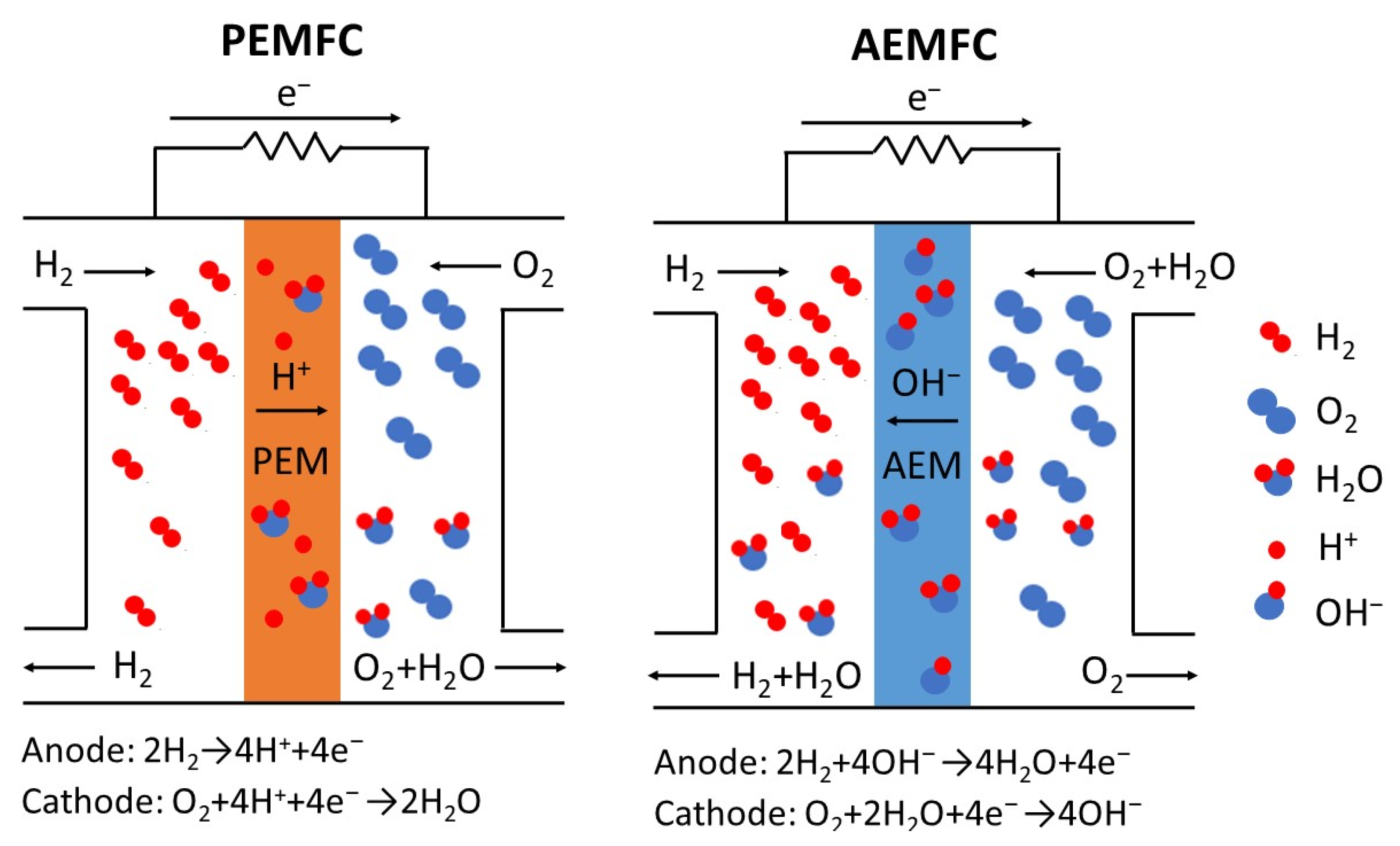
Figure 1. Schematic diagrams of a PEMFC and an AEMFC, with the relevant electrode reactions. For PEMFCs, the O2 source is air. For AEMFCs pure O2 or CO2-free air is used as the cathode feed.
Energies 14 06709 g001
Figure 2. A simplified schematic of an electrospinning system.
Energies 14 06709 g002
Figure 3. (a) Schematic diagram of a nanofiber composite PEM. Reproduced with permission from Ref. [56]. (b) Variation of in-plane proton conductivity with RH at 80 °C for two nanofiber composite membranes and for Nafion 212. Reproduced with permission from Ref. [57]. (c) Two kinds of nanofiber composite Nafion/PPSU membrane structures from the same electrospun dual-fiber mat. Reproduced with permission from Ref. [79]. (d) Polarization curves at 80 °C for a 3M Co. PFSA ionomer MEA (with a 3M 660 EW PFSA/PPSU nanofiber composite membrane) and a Nafion ionomer MEA (with a Nafion 211 membrane). (▲) 3M MEA at 93% RH; (■) 3M MEA at 75% RH; (♦) 3M MEA, at 50% RH; (•) 3M MEA at 25% RH; (Δ) Nafion MEA at 93% RH; (□) Nafion MEA at 75% RH; (◊) Nafion MEA at 50% RH; (○) Nafion MEA at 25% RH. Reproduced with permission from Ref. [59]. (e) The results of an OCV hold membrane durability test, where the change in OCV at 90 °C is plotted as a function of time for MEAs incorporating: (a) a non-reinforced Aquivion membrane, (b) a membrane composed of PSU fiber-reinforced Aquivion, and (c) a membrane composed of Aquivion reinforced with 30 mol% PSUT nanofibers. Reproduced with permission from Ref. [60].
Energies 14 06709 g003
Figure 4. Freeze-fractured cross-section SEM images of nanofiber composite membranes; (a) a tri-layer 825 EW PFSA (matrix)/PAI (fiber) composite membrane with 80 wt.% PFSA with a low PAI nanofiber content in the outer layers and a higher PAI fiber content in the inner layer. Reproduced with permission from Ref. [55]. (b) An 825 EW PFSA (matrix)/PAI (fiber) composite membrane with 80 wt.% PFSA where the PAI fiber content is continuously and symmetrically changing from the membrane centerline (high PAI fiber content) to the membrane surfaces (low PAI content). Reproduced with permission from Ref. [55]. (c) Pore-filled cPPSA (matrix)/PPSU (fiber) composite membrane with 75 wt.% cPPSA. Reproduced with permission from Ref. [62].
Energies 14 06709 g004
Figure 5. (a) Preparation of NH2-UiO-66 coated fibers. Reproduced with permission from Ref. [63]. (b) Preparation route for sulfated SnO2 hollow nanofibers. Reproduced with permission from Ref. [64]. (c) Sol-gel reaction of precursors TEOS and CSPTC to form a sulfonated silica network. Reproduced with permission from Ref. [19].
Energies 14 06709 g005
Figure 6. (a) Scheme for reacting brominated poly(phenylene oxide) with hexamethylenediamine crosslinker. Reproduced with permission from Ref. [70]. (b) Fabrication process for making a composite membrane with QPAES nanofibers. Reproduced with permission from Ref. [71]. (c) TEM image of an MWCNT-embedded in an electrospun nanofiber and a possible mechanism of hydroxide transport in a MWCNT/IMPS co-electrospun composite membrane. Reproduced with permission from Ref. [72].
Energies 14 06709 g006
Figure 7. Relationship between composite membranes price and fuel cell stack (system) annual production rate, from an economic study carried out by strategic Analysis, Inc. [88]. All membranes are 14 μm in thickness with 95% Nafion PFSA ionomer. Reproduced with permission from Ref. [88].
Energies 14 06709 g007
Table 1. Characteristics and components of PEMFC and AEMFC.
Fuel Cell TypesPEMFCAEMFC
Conductive ionH+OH
Typical membrane ionomerPFSAQuaternized polyphenylene oxide (QPPO)
Anode catalystPtPt, PtRu, Ni alloy
Cathode catalystPt, Pt/C, PtCo/C, PtNi/CPt, Ag
DisadvantageExpensivePoor durability, very expensive
AvailabilityWidely available as bulk polymer, in films, and in liquid dispersionsLimited availability in bulk quantities
Table 2. Summary of electrospun PEMs and their properties.
NanofiberMatrixMembrane Thickness (μm)Ionomer Fraction (%)Effective IEC (mmol/g)H+ Conductivity (mS/cm)H2 Crossover (mA/cm2)Reference
-Nafion 1251000.91100 (at 80 °C, 90% RH)4.1 (at 80 °C, 200 kPa backpressure, 100% RH)[55]
sPAESNOA 6339701.6586 (at 25 °C, liq. water)-[56]
733 EW PFSANOA 6375701.36160 (at 80 °C, 80% RH)-[57]
Nafion 1PPSU31700.6370 (at 25 °C, liq. water)1.3 (at 80 °C, ambient pressure, 100% RH)[58]
660 EW PFSAPPSU51721.23166 (at 80 °C, 80% RH)-[59]
PSUTAquivion 230700.98180 (at 80 °C, 95% RH)-[60]
PVDFNafion 148600.5455 (at 25 °C, liq. water)-[61]
PAI825 EW PFSA20800.9791 (at 25 °C, liq. water)4.9 (at 80 °C, 200 kPa backpressure, 100% RH)[55]
PPSUcPPSA100754.70429 (at 80 °C, 90% RH)-[62]
sPAES/sPOSSNOA 6370702.2494 (at 30 °C, 80% RH)-[17]
825 EW PFSA /sPOSSNOA 63-742.41357 (at 80 °C, 90% RH)-[18]
NU6@PPNFSPEEK9697-133 (at 60 °C, 100% RH)-[63]
Sulfated SnO2SPPESK80931.72227 (at 80 °C, 80% RH)1.7 (at 80 °C, ambient pressure, 100% RH)[64]
PVDF825 EW PFSA /S-SiO240801.4689 (at 20 °C, liq. water)-[19]
P(VDF-TrFE)/S-SiO2Nafion 1108--102 (at 70 °C, 100%RH)-[65]
1 1100 EW PFSA (0.91 mmol/g IEC). 2 830 EW PFSA (1.20 mmol/g IEC).
Table 3. Summary of electrospun AEMs and their properties.
NanofiberMatrixMembrane Thickness (μm)Ionomer Fraction (%)Effective IEC (mmol/g)OH Conductivity (mS/cm)Reference
-FAA-3-5047–531001.8540[35]
QAPSPPSU-631.5640 (at 23 °C, liq. water)[66]
QAPSPDMS--1.8169 (at 80 °C, 90%RH)[67]
QAPS/crosslinkPPSU-652.0565 (at 23 °C, liq. water)[68]
IMPS/crosslinkPPSU-651.9949 (at 23 °C, liq. water)[69]
QPPO/crosslinkPPSU40502.0066 (at 23 °C, liq. water)[70]
QPAESQPAES-1001.5183 (at 30 °C, liq. water)[71]
IMPS/MWCNTIMPS/MWCNT79991.5368 (at 30 C, liq. water)[72]
IMPSIMPS1001001.7838 (at 20 °C, liq. water)[73]
QPAES/crosslinkQPAES-1003.3166 (at 23 °C, liq. water)[74]
PES-G-OHVBTC-100-46 (at 20 °C, liq. water)[75]
Publisher’s Note: MDPI stays neutral with regard to jurisdictional claims in published maps and institutional affiliations.

