1. Introduction
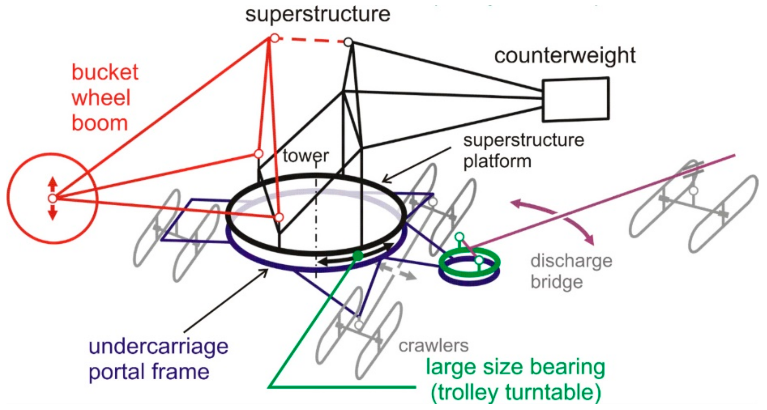
A large-scale heavy-duty machine often consists of a body that rotates around a vertical axis. Examples of such machines include bucket-wheel excavators, stackers and loader-stackers (
Figure 1).
Slewing bearings play a significant role in the proper and reliable operation of heavy machines. These elements enable the machine body to move relative to the undercarriage in bucket-wheel excavators, stackers, stacker-reclaimers, draglines, cranes and also in wind turbines. Due to the large size of these machines, their slewing bearings are subjected to high loadings [
1,
2,
3,
4,
5,
6,
7,
8,
9].
In order to operate, these machines strictly depend on the condition of the slewing bearings. Therefore, any inaccuracies or errors in their design or during their manufacture can lead to serious issues during operation, which is why a monitoring system should be implemented. Among the most severe consequences of defects in the design or manufacture of races and rolling elements are their local strain and decreased durability and load-carrying capacity [
1,
10,
11,
12].
There are several studies that focus on developing and utilizing methods that help to detect errors, predict and prevent failures and estimate the remaining life of large-scale bearings [
13,
14,
15,
16,
17,
18,
19,
20,
21,
22,
23]. The most advantageous methods include statistical analyses based on advanced indicators such as kurtosis, squared envelope spectrum, protrugram, as well as empirical mode decomposition and ensemble empirical mode decomposition. These tools are useful to study and identify defects [
13,
14]. Reference [
15] presents a complex strategy for residual life prediction. It involves a data-driven failure rate and a reliability assessment by means of vibration signals. An evaluation of contact forces and stresses in mating surfaces in bearings is also very important in terms of life prediction as those parameters influence fatigue conditions [
24,
25,
26]. Reference [
19] presents a novel diagnostic method which is less prone to errors and is designed to detect initial faults. A combined analytical and numerical method described in [
20] helps in assessing the dynamics of large-scale bearings, including post-hardening risk which directly influences the mechanical properties of such elements and thus their reliability and durability. Another study presents a complex approach to controlling the deteriorating technical condition of slewing bearings [
21]. It utilizes, among others, the Hidden Markov Model, Gated Recurrent Unit, Robust Local Mean Decomposition and Hilbert transform, to estimate the residual life. Another advanced study focused on predicting the residual life of slewing bearings is described in [
22].
The identification of critical components can help to focus the diagnostic process on certain elements. Reference [
18] shows a method which uses relevant sensors after such a component is selected. By applying certain modeling tools, it is possible to evaluate the technical condition and estimate the residual life of the device under study.
When analyzing the technical state of large-scale bearings and predicting their remaining useful life, it is necessary to monitor the condition of greases or bolt connectors which strictly influence the operation of the entire system [
27,
28]. These issues should be foreseen and taken into account already in the designing process. What is also worth mentioning are roller load tests, which help to diagnose large-scale bearings in mining machines. They are based on the assessment of the quality of geometry and can help predict the residual life while identifying maximum loading values. A more detailed description of this method can be found in [
29,
30,
31,
32].
What is more, when devising diagnostic procedures, it is important to include recommendations for potential repairs. Detailed procedures and rules for repairing load-bearing structures which deteriorate under loads transmitted by road wheels are proposed in [
33,
34].
To properly formulate a diagnostic procedure, the knowledge of the wear mechanism is invaluable. Reference [
35] is a case study of raceways of slewing bearings whose technical properties degrade. The study includes a microstructure analysis, while in Reference [
36], stress–strain characteristics for loading conditions are obtained by means of strain gauges.
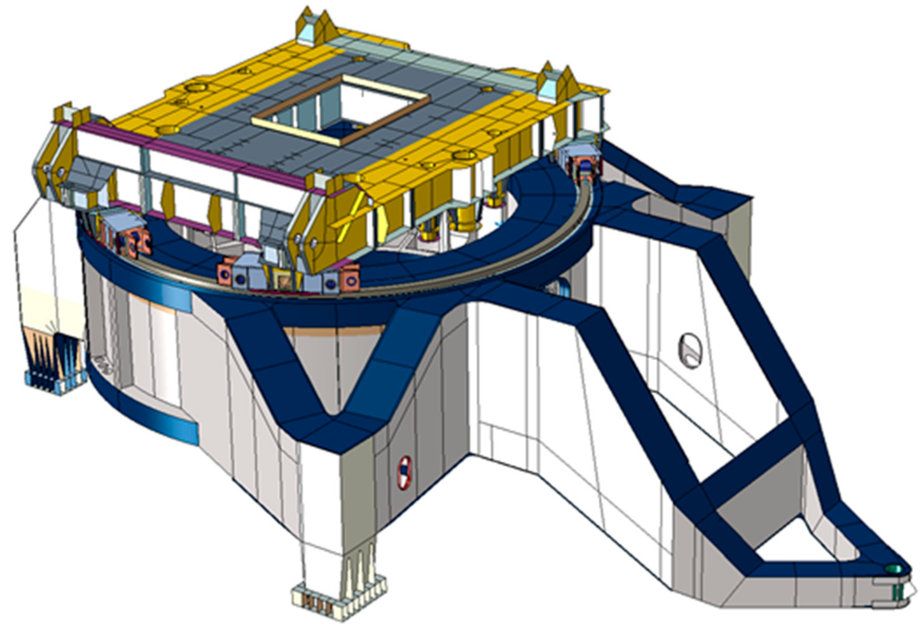
2. Typical Solutions for Slewing Units in Large-Scale Heavy-Duty Machines
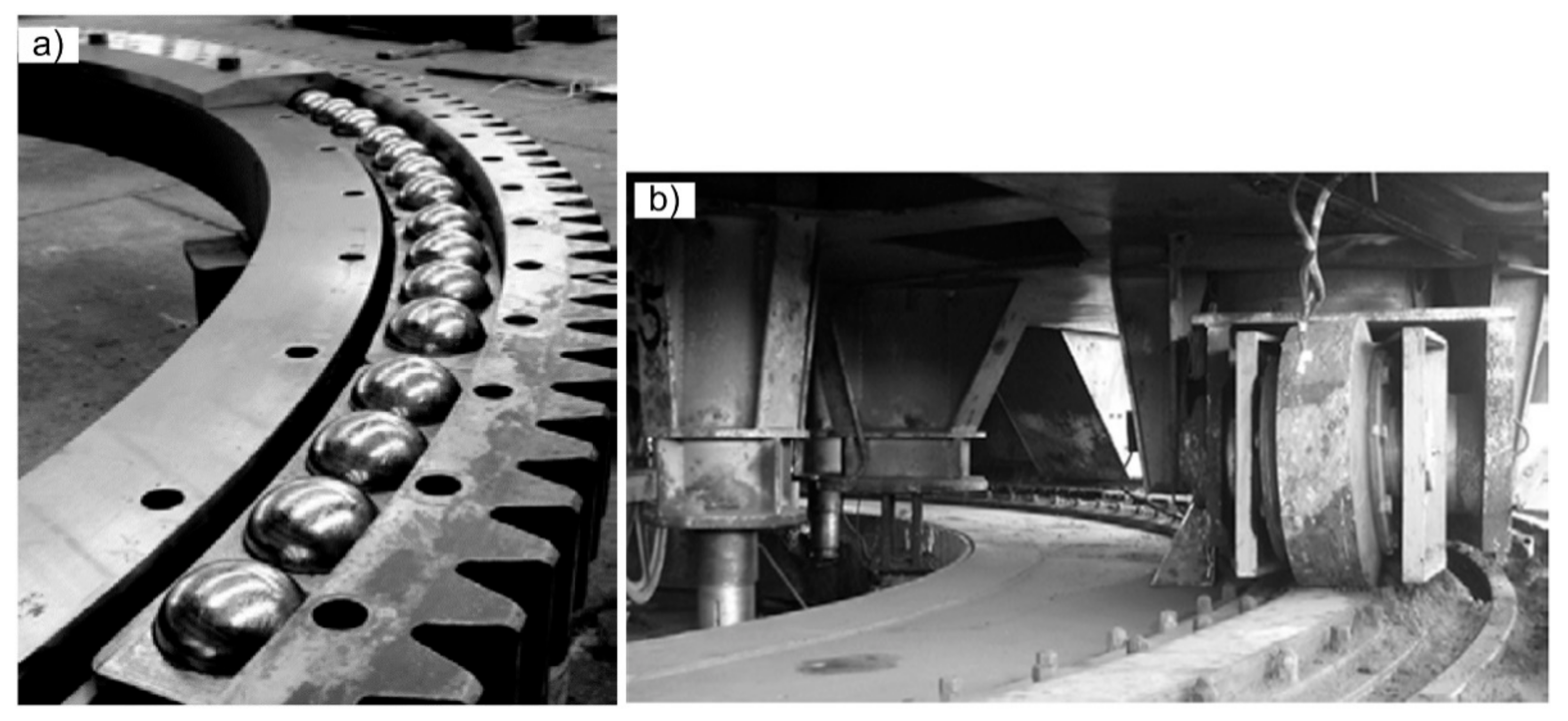
In general, systems of slewing units in heavy-duty machines are based on the following elements (
Figure 2):
Large-diameter rolling bearings and slewing bearings,
Wheeled bogies running on a rail track,
Column rotary joints.
The main advantages of the first solution are the “soft” uniform distribution of loads and lower resistance to motion. However, this solution also has some disadvantages, for instance vulnerability (lower resistance to damage), non-reparability, requirement of higher stiffness of the girder ring and higher costs.
The second above-mentioned solution has advantages such as lower costs, the possibility to replace the damaged components and easier maintenance. However, the disadvantages of this type of construction include “hard” distribution of loads (higher concentration of loads under the rails) and relatively higher resistance to motion.
Turntables with bogies were adopted much earlier than ball bearings because this solution is less complex. In this case, the load from the body is transferred through a rocker arm system to a set of road wheels moving on a circular rail track [
6]. The purpose of rocker arms is to equalize the loads transferred by individual wheels, which prevents excessive pressure on the wheel–rail contact and thus the degradation of the supporting components.
In the bogie turntables, high-pressure points appear between the wheels and the raceway. In order to ensure stability, four bogies are used with several wheels mounted in each bogie. Due to the statically indeterminate support, unequal loads appear when there is an unevenness on the raceway [
5].
One of the basic requirements for the bearing nodes of large-scale heavy machinery is to obtain an even distribution of loads, which is hampered by friction occurring in kinematic pairs as well as the differences in stiffness of the supporting components.
An even distribution of loads is extremely important to ensure adequate durability, reliability and safety of the supporting structure. This is particularly relevant due to the large masses of this type of machinery, often reaching 1000 tons or more.
Due to their long-term operation, large heavy-duty machines are subject to various degradation processes: corrosion, fatigue, material aging and flow, strain, cracks, loss of lubricating properties of greases, galling of the pins in the rocker arms, etc. In particular, fatigue is a typical material degradation process that affects even properly operated machine bearing nodes, and is the result of cyclical loads that occur when rolling elements are shifted.
In general, a rotating node may fail for many reasons, but it is usually possible to determine the dominant cause. One of the main reasons is the uneven distribution of loads. It results not only in the concentration of stresses or excessive pressures on the “wheel–rail track” interface, but also causes local overloads of the supporting structure under the running rail. This may lead to a decrease in the ring girder load capacity due to material fatigue.
These additional local stresses occur under the wheeled bogies of slewing units and are usually not considered in preliminary calculations of a steel structure, although in some cases, they can reach relatively high levels [
12].
For this reason, diagnostic procedures and effective monitoring of the technical condition of elements of bearing nodes in the bodies of large heavy-duty machinery are very important. Any negligence in this area may endanger the safety of operation of these machines, and in extreme cases, may lead to a disaster.
3. Materials and Methods
Until a certain moment, the degradation of the bogie rotation units in machines that operate for extended periods of time is slowly varying in character. The main processes which contribute to this degradation include abrasive wear and scuffing of the rocker arm bolt joints, as well as corrosion, aging of materials and development of cracks (especially in the area of welded joints).
However, above a certain threshold, the slowly varying degradation can suddenly lead to catastrophic failures.
In order to successfully prevent such events, it is therefore necessary to use effective methods for identifying and monitoring these degradation processes as well as for diagnosing the technical condition of rotation nodes in heavy machinery.
Since the elements of the rotating unit are not easily accessible, especially the bogies and the track, it is virtually impossible to assess their technical condition on the basis of symptoms sensed by operators or maintenance engineers while the machine is in operation.
In this context, there is a need to develop an effective diagnostic method based on the analysis of the so-called failure-oriented signals, which are obtained by measuring relevant physical quantities, e.g., strains or loads. At the same time, it should be possible to use such a method while the machine under study is operating.
In the preliminary stage, we analyzed the usefulness of various methods, including the classical methods of vibroacoustic diagnostics and thermal diagnostics. These methods were tested on various large heavy-duty machines.
The vibration diagnostics method was used, among others, to assess the technical condition of large-scale bucket conveyors [
12,
37]. The method of acoustic diagnostics was also successfully used to assess the technical condition of caterpillar chains. The thermal diagnostics method has proven successful in diagnosing more accessible assemblies, such as drive units and rollers of belt conveyors.
However, in the case of large-scale bogie units, one of the basic indicators of the quality of their operation is the degree of uniformity of load distribution on the chassis structure (ring girder). This fact had to be taken into consideration when deciding which diagnostic method to choose.
As a consequence, our method uses a diagnostically useful signal as the carrier of information which is clearly correlated in terms of quality and quantity with the character of the distribution of loads acting on the rolling elements (wheels of bogies).
It is virtually impossible to directly measure the loads acting on the “wheel–rail” interface because it would require measuring sensors to be installed along the rail surface, in which case these sensors would interfere with the operation of the assembly or could be damaged. However, it is possible to estimate the distribution of these loads on the basis of strain–stress measurements in the substructure (ring girder). It is important to place the measurement points in the zones where working loads have maximum impact (to obtain the maximum sensitivity of the measurement systems), while avoiding the zones of local stiffening (ribs, diaphragms, etc.), which could cause stress irregularities.
Based on the above-mentioned considerations, strain (stresses) was selected as the diagnostic signal to be used with the presented method for assessing the technical condition of bogie rotation units. An additional advantage of this signal is that it is also useful for assessing the stress state of the support structure of the rotation node (ring girder).
This article focuses on the identification of symptoms of deterioration in the technical condition of rotating joints, determination of the threshold values of these symptoms and interpretation of the final results in the context of their relevance for assessing the stress of the chassis structure of the tested large heavy-duty machine.
With this in mind, the procedures for diagnostic signal processing, such as techniques of extracting useful components from diagnostic signals under disturbance conditions and the methods of a statistical analysis of the results, are not described in detail.
3.1. Theoretical Basis of the Diagnostic Method
Based on the above-mentioned reasons, we propose a method of assessing the technical condition which uses the strain of the ring girder under loads from road wheels of the bogies of the rotation node as the diagnostic signal. Strain is measured by means of strain gauges installed in the so-called critical cross-sections of the ring girder. The location of these cross-sections is determined on the basis of strength analyses using the finite element method.
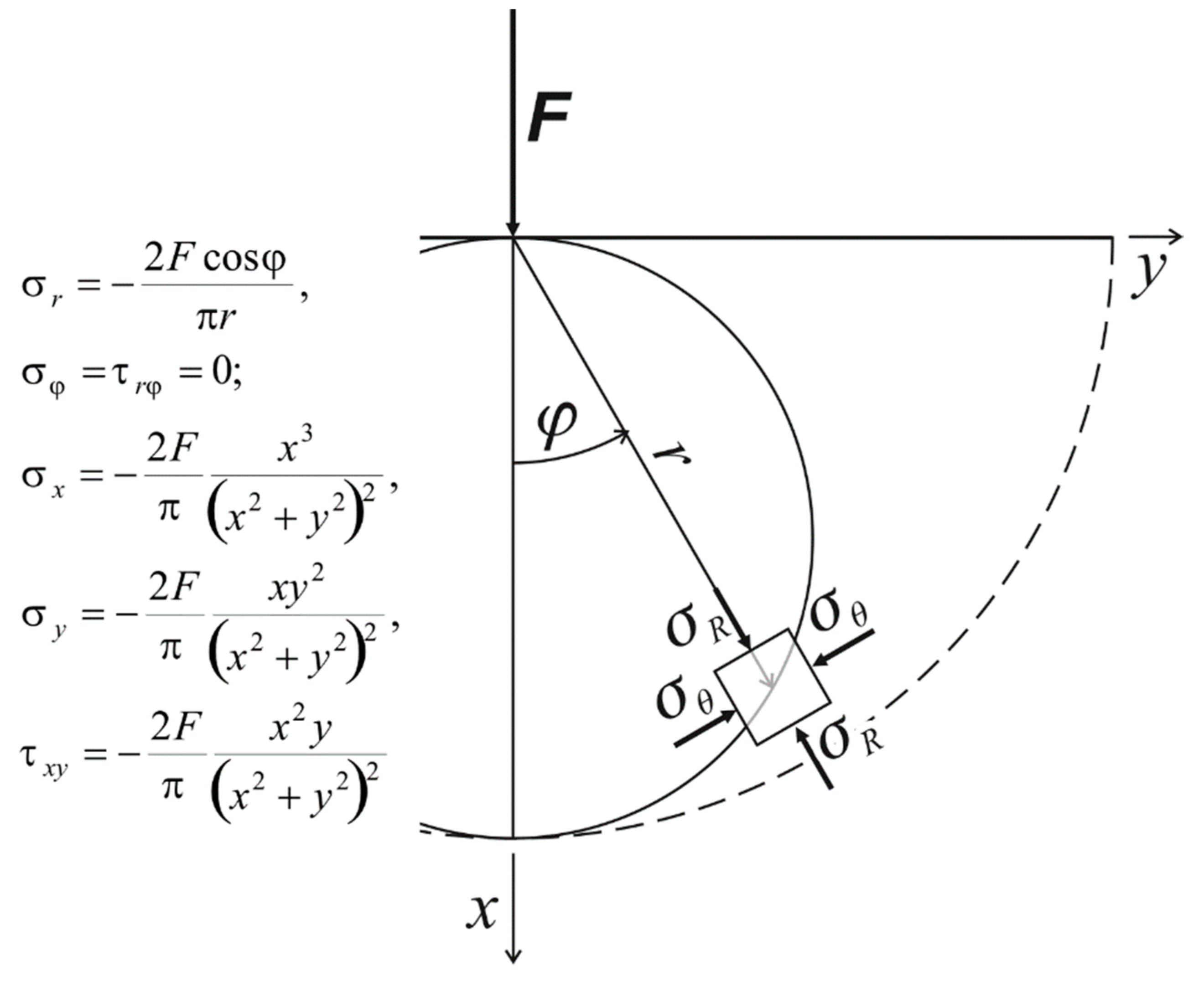
The theoretical basis of the proposed diagnostic method is the analysis of the stress field in an isotropic elastic half-space under a vertical point load. An analytical description of such a stress field is provided in the classic Flamant solution, which states that the vertical stresses,
σx, generated on the substrate (ring girder) expressed in the cylindrical coordinate system (
r,
x) are described by the following Equation (1):
In the case of a system of “
n” point loads acting along the track of the rolling node of the rotation, vertical stresses in the ground can be expressed by Equation (2):
where:
—loading force,
—coordinate of the “k” point load.
In the plane stress state, the strain,
, in the direction of the force can be calculated from Equation (3):
where:
φ—the angle between the direction of the force and the line extending from the point where the force is applied,
—Poisson’s ratio.
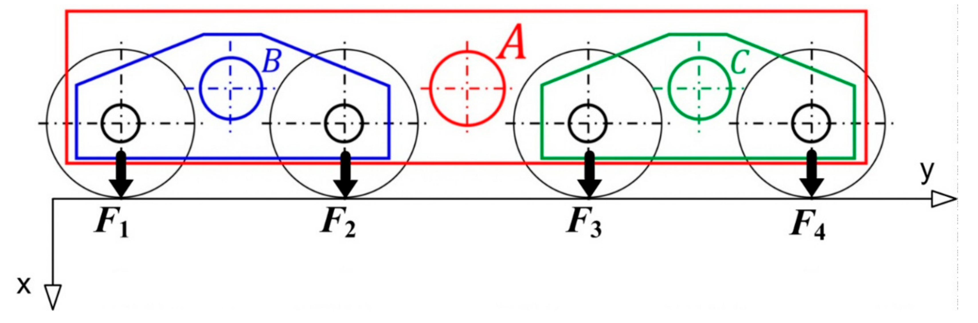
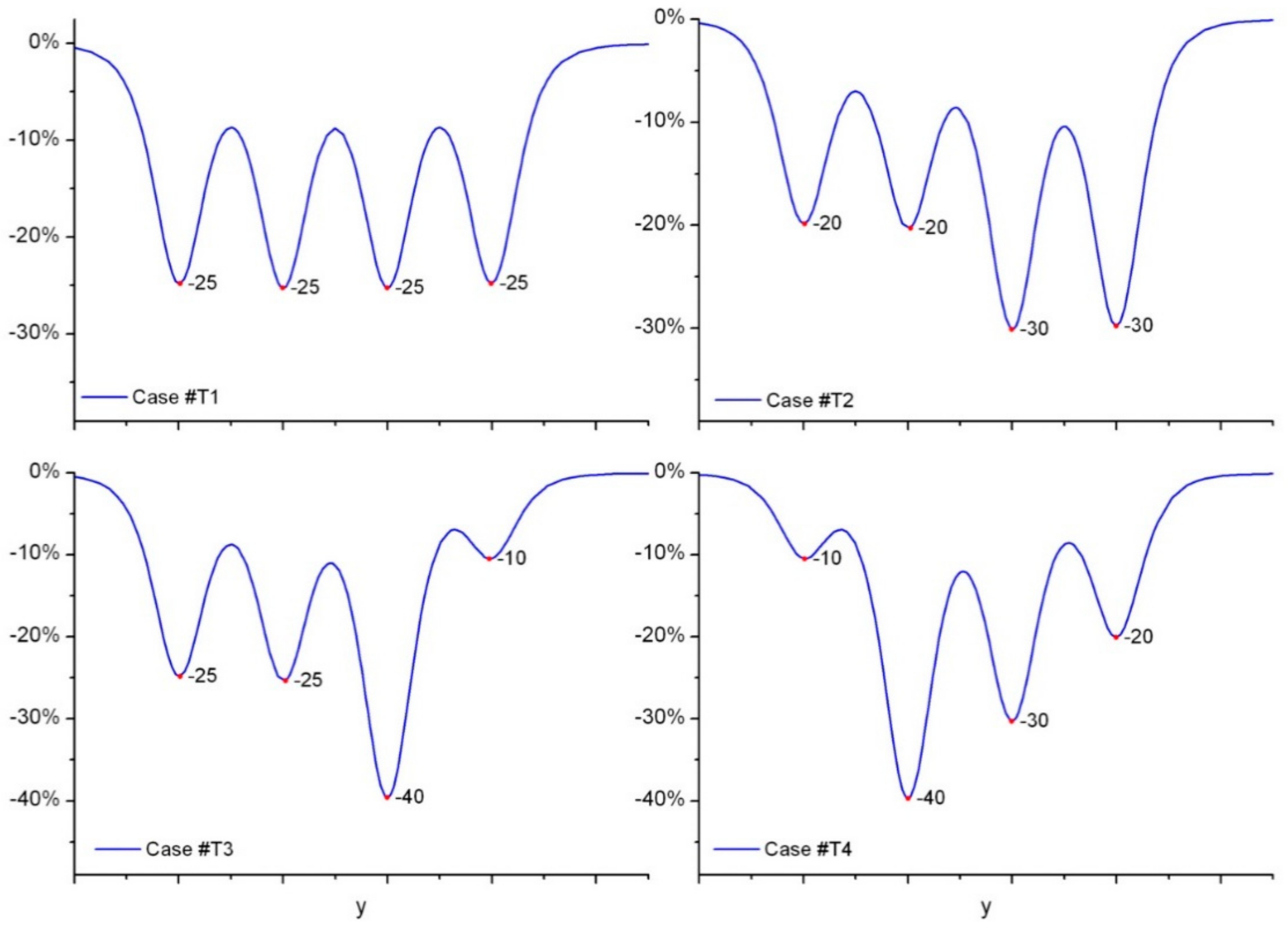
The following four variants of load distribution in individual wheels of the bogies of the machine rotation node were considered (
Figure 4):
Case #T1: The large rocker arm A and both small rocker arms B and C work properly. The load is evenly distributed to all wheels of the bogie assembly. The wheel load scheme is as follows: {F1 F2 F3 F4} = {25%, 25%, 25%, 25%}, i.e., the loading of every wheel expressed as a percentage of the total load on the bogie is equal to 25%.
Case #T2: The large rocker arm A does not work properly (e.g., due to partial seizure of the main pivot). The loads are not distributed evenly, i.e., the wheels of the rear small rocker arm C are subject to higher loads than the wheels of the front small rocker arm B. The wheel load scheme is as follows: {20%, 20%, 30%, 30%}.
Case #T3: The large rocker arm A works properly but the rear small rocker arm C does not. The loads are not distributed evenly, i.e., the rear wheel of the rear small rocker arm C is subject to a higher load than the front wheel of the rear small rocker arm C. Both wheels of the front small arm B are evenly loaded. The wheel load scheme is as follows: {25%, 25%, 40%, 10%}.
Case #T4: The large rocker arm A does not work properly (e.g., due to partial seizure of the main pin) nor does the rear small rocker arm C (e.g., due to partial seizure of the pin). The loads are not distributed evenly. The rear small rocker arm C is subject to higher loads in relation to the front rocker arm B. Moreover, the rear wheel of the rear small rocker arm C is also subject to higher loads compared to the front wheel of the rear small rocker arm C. The wheel load scheme is as follows: {10%, 40%, 30%, 20%}.
Figure 5 shows the results of the simulation of the distribution of normal stresses generated in the ground for each of the above-mentioned cases of wheel loading. These results were obtained on the basis of the theoretical Flamant model.
Simulations of load distribution based on the Flamant model show that the peak values of normal stresses under individual wheels in relation to the sum of all four peaks correspond to the percentages of load values per wheel.
For example, in case #T3, the peak stresses under the wheels of the bogie (expressed as percentage) are respectively {−25%, −25%, −40%, −10%}, which corresponds to the load system assumed for case #T3.
Similarly, in case #T4, the stress peaks are as follows: {10%, 40%, 30%, 20%}, which is in line with the load system adopted for variant #T4.
Thus, the results of simulations based on the theoretical Flamant model confirm that the qualitative nature and the peak values of normal stresses are clearly correlated with the distribution of loads acting on the bogie’s wheels.
This proves that normal stresses generated in the subgrade can be used as a diagnostically useful signal. On this basis, it is possible to assess the distribution of working loads on the wheels and the technical condition of the bogie assembly of the heavy machinery rotation node.
An important advantage of using stresses as a diagnostic signal is the possibility to perform continuous monitoring of the technical condition of the rotation nodes of large heavy equipment machinery in actual operating conditions.
3.2. Numerical Basis of the Diagnostic Method
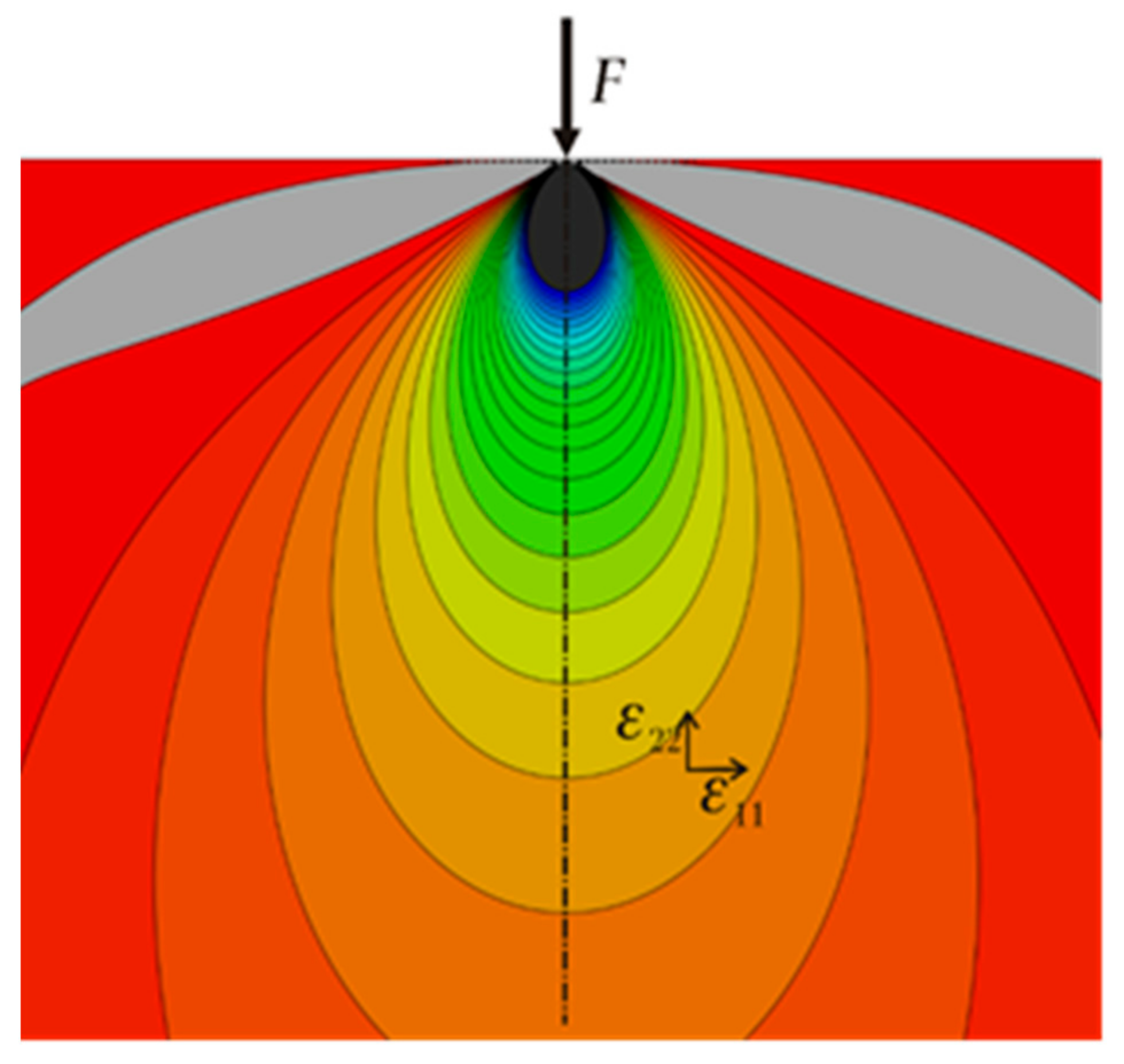
The formulas derived by Flamant are solutions to the field of stresses and strains in an elastic half-plane loaded with a concentrated force.
Figure 6 shows the field of strain in the force direction in a semi-infinite body without imperfections, calculated by FEM. The structures of real rotating support systems differ significantly from their theoretical models. Firstly, the spar flange is not flat, but has the shape of a cylindrical surface. Secondly, the force is introduced into the system through the massive beam of the running rail and can act eccentrically. Thirdly, the spar flange is usually stiffened by diaphragms, ribs and bracket leads. These significant deviations from the theoretical solution must be taken into account both when selecting the location of sensors and when interpreting the results of measurements.
A fragment of the model of the portal frame of an excavator undercarriage including the zone where strain gauges are to be located is shown in
Figure 7. Various thicknesses of the sheets are marked with different colors.
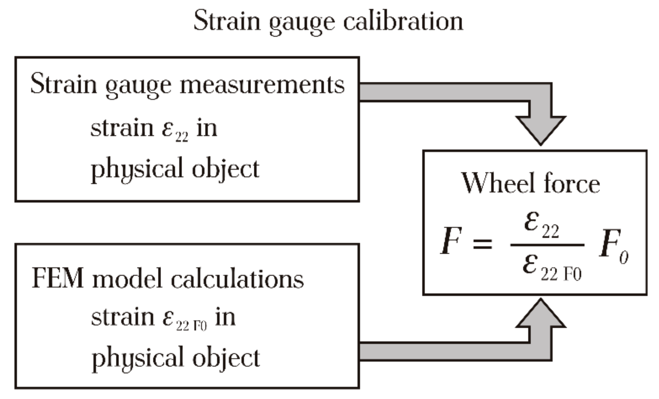
The strain field determined by FEM also allows the sensors to be calibrated numerically, which is often not possible on a physical object.
Without calibration, it is impossible to determine the exact values of the forces exerted by individual wheels (
Figure 8). However, since the load ratios between individual wheels of the bogie rolling unit are known, the measurement results can be used to diagnose the state of kinematic pairs in the tested assembly.
4. Application of the Presented Diagnostic Method
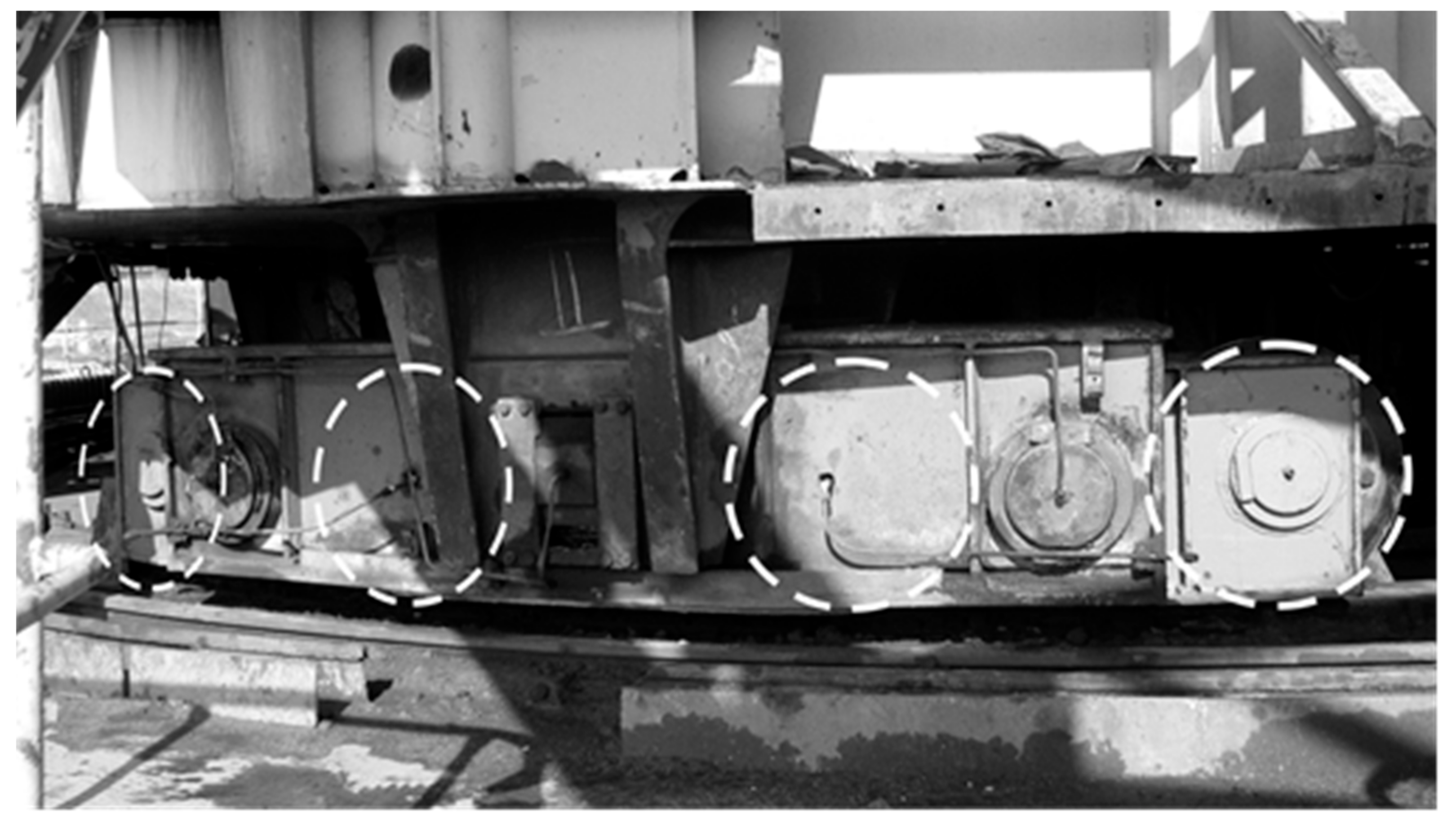
This diagnostic method was applied during a comprehensive study of six similar bucket-wheel excavators (
Figure 9) whose support systems are based on wheeled bogies running on rail tracks (
Figure 10).
In each of the tested excavators, six critical cross-sections (
Figure 11) were selected in the ring girders constituting the track-bed of the circular rotation assembly. The location of the measurement cross-sections was determined based on a stress analysis of the girders using the finite element method. This method allowed us to obtain the highest sensitivity of the measurement systems.
Electrical resistance strain gauges were used for diagnostic measurements. At each critical cross-section, strain gauge systems (strain gauge rosettes) were installed on the spar web. The Saint Venant’s principle was taken into consideration when selecting the distance of the measuring systems from the top flange, which serves as the rail support of the circular rotation unit. The distances from the acting loads were sufficiently large to be in accordance with the Saint Venant’s principle.
The measurements were taken while the excavator bodies made a full turn to the left and to the right.
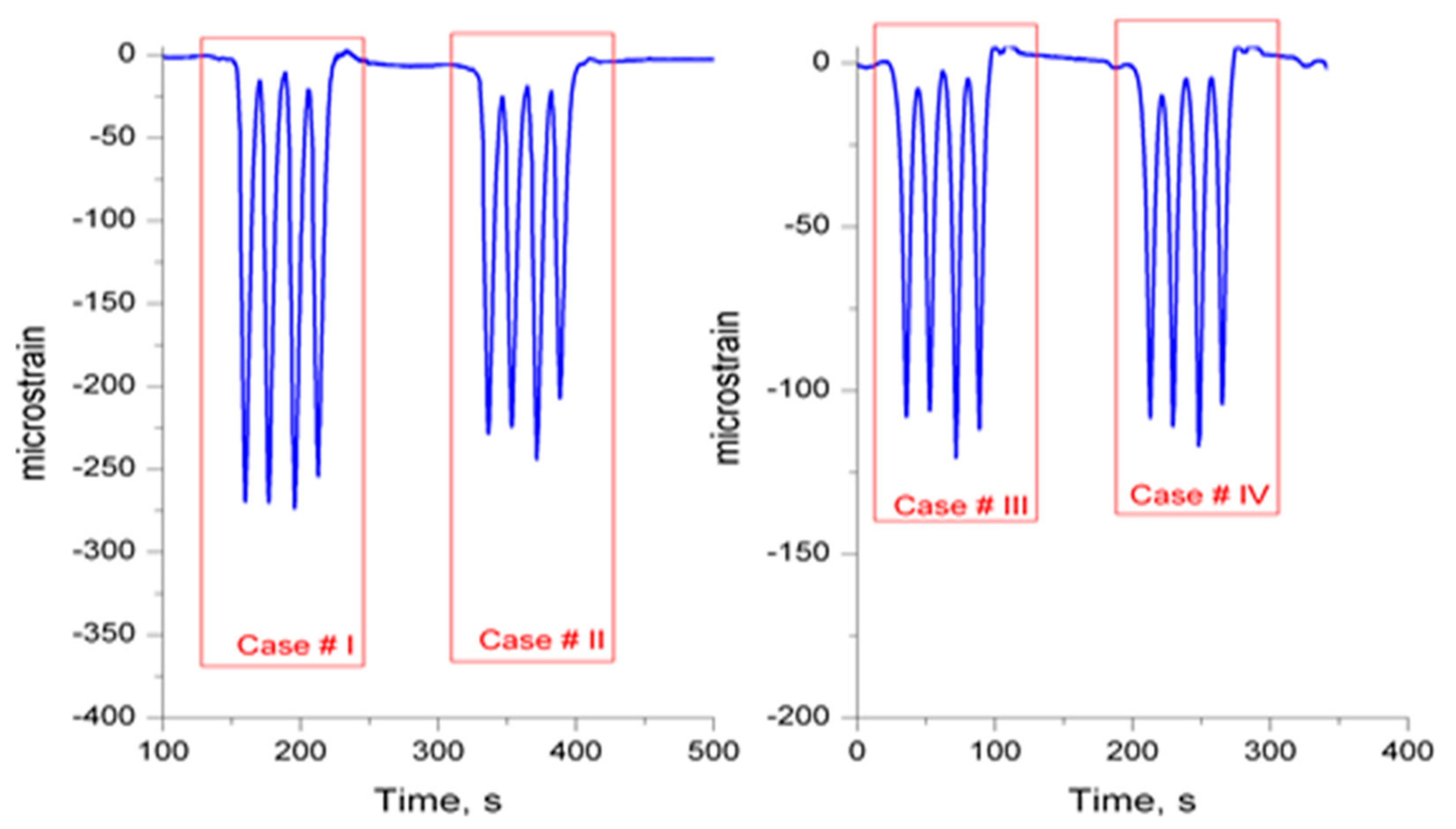
Examples of typical time courses of local strain in the ring girder of one of the tested bucket-wheel excavators are presented in
Figure 12,
Figure 13 and
Figure 14.
In the vast majority of cases, the bogies of the slewing units in the tested excavators were in a satisfactory technical condition, despite many years of operation, which was evidenced by a quasi-uniform distribution of strain in the ring girders under the road wheels.
Figure 12 shows examples of cases #I to #IV.
Nevertheless, in the course of the study, several cases of improper technical condition of bogies were diagnosed based on an uneven distribution of strain under the road wheels. These cases were detected in two excavators which have operated for the longest period of time (over 20 years).
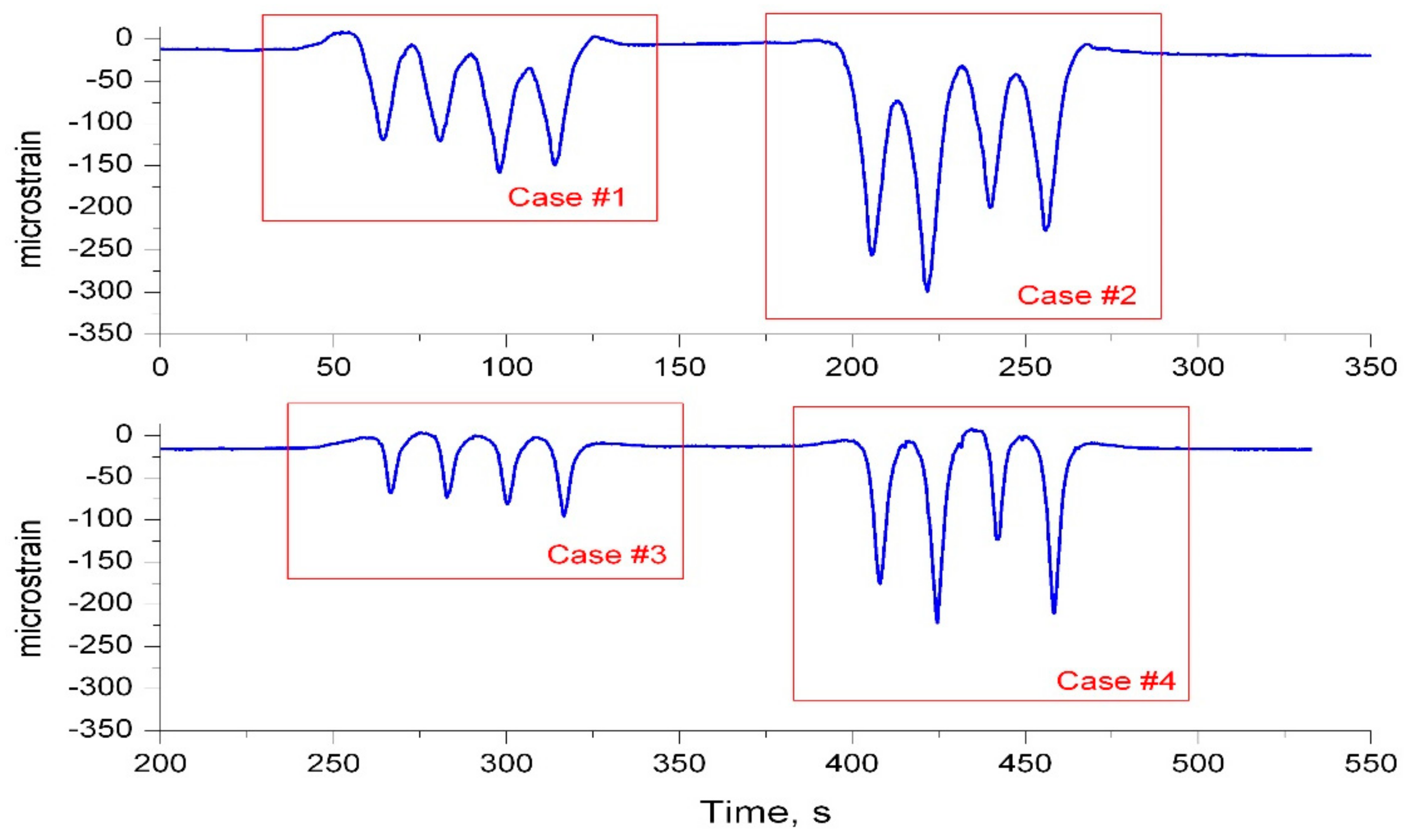
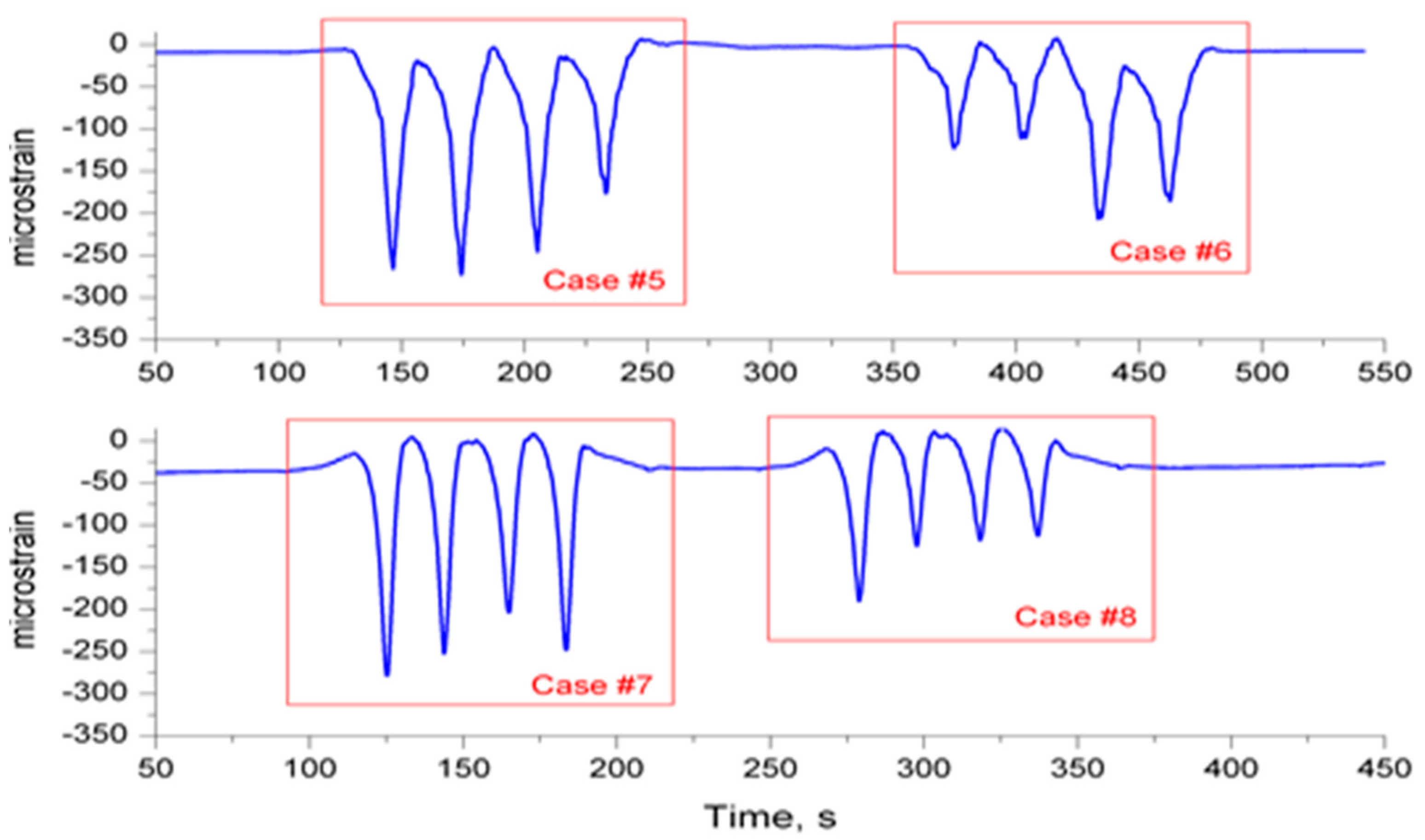
Several characteristic cases of a non-uniform strain distribution (denoted as case #1 to case #8) are presented in
Figure 13 and
Figure 14.
4.1. Analysis of the Research Results
It should be emphasized that the subject of this study concerns large-scale wheeled excavators operating for 20 years or more. One of the main objectives of this research was to diagnose the rotating units used in these machines. In each of the tested excavators, the load from the body was transferred through the rocker arm system to a set of road wheels moving along a circular rail supported by the ring girder.
In bogie turntables, the load from the body is distributed over a relatively small number of rolling elements, i.e., the road wheels, and therefore the load distribution is generally “hard” as opposed to the so-called “soft” distribution in slewing bearings where the load is distributed over multiple rolling elements.
The load distribution depends largely on the quality of the rocker arm assemblies consisting of a large rocker arm and small rocker arm, as well as their pin connections.
However, degradation processes such as corrosion, contamination of friction pairs, or loss of lubricating properties of greases may cause, among others, the gradual galling of the pins in bogie rocker arms, which is sometimes one of the main causes of uneven load distribution.
With this in mind, the degree of uniformity of load distribution on the road wheels of individual bogies was adopted as the criterion for assessing the technical condition of the bogie wheels in the tested excavators.
As for the diagnostic signal, we used the strain/stresses generated in the foot of the ring girder by loads from road wheels in the bogies of the excavator rotation unit. The following descriptive quantities were adopted as diagnostic measures:
—mean absolute deviation, —mean value and —peak value of strain under wheeled bogies,
, —moment of friction and normal force in the pin joint, and r—radius of pin.
Based on the above-mentioned indicators, we performed a diagnostic assessment of individual bogies of the rotation units in the tested excavators.
The article presents only four examples of test results. The limit values for the coefficient of variation and the impulse factor, equal to 8% and 15% respectively, were determined on the basis of all results.
4.2. Examples of Quasi-Uniform Pressure Distribution
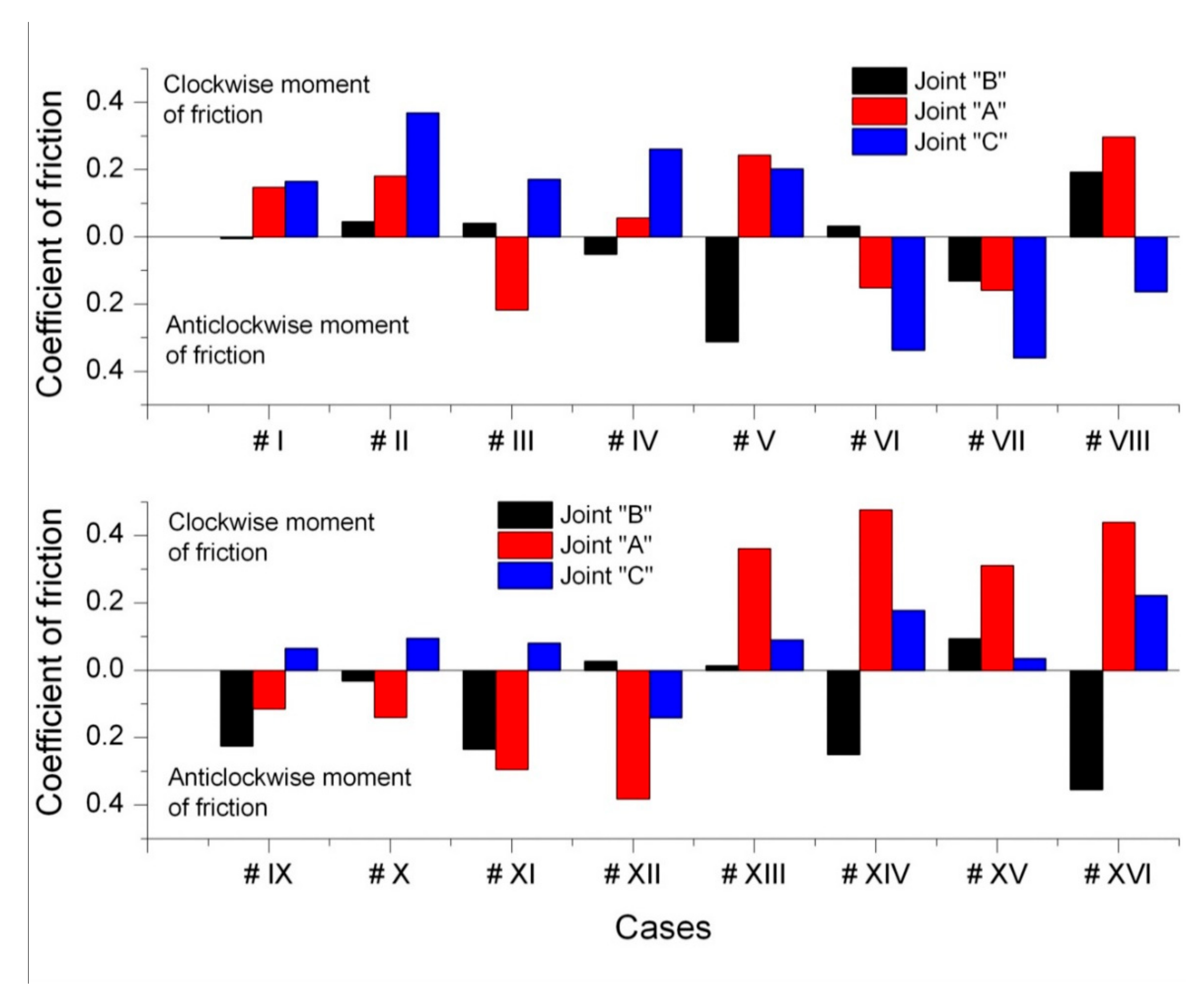
Figure 15 and
Figure 16 present examples of calculation results of diagnostic indicators for four characteristic cases of quasi-uniform distribution of loads on road wheels.
The research revealed that in most cases, there was a quasi-uniform distribution of loads on the running wheels of the bogies in the tested excavators. The analysis of the measurement results showed that in these cases:
The impulse factor did not exceed 1.15 because the peak values of strain under wheeled bogies did not exceed the mean value by more than 15%, and the coefficient of variation did not exceed 8%.
The coefficient of friction in the pin joints of wheeled bogies, determined on the basis of the analysis of the results of measurements, did not exceed the value of μ = 0.4, except for case #XIV and case #XVI, where the friction coefficient at node “A” was slightly higher. These results suggest that there was no galling of the rocker pins.
The above values indicate that the wheeled bogies in the tested bucket-wheel excavators are in good condition.
4.3. Cases of Non-Uniform Strain Distribution
The research also revealed several cases of an uneven distribution of loads on the running wheels of the bogie units. These cases are designated as case #1 to case #8 and the strain distributions are shown in
Figure 13 and
Figure 14.
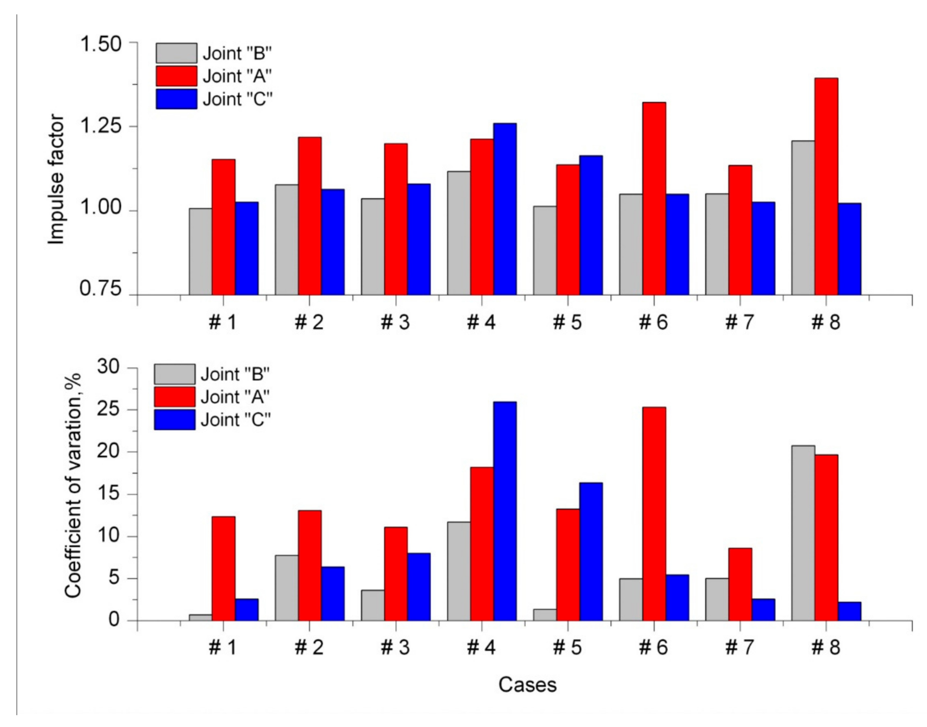
Figure 17 and
Figure 18 show the numerical values of the adopted diagnostic indicators for cases #1 to #8, i.e., the coefficient of variation, the impulse factor and the coefficient of friction. For cases #4, #6 and #8, the coefficient of variation was unfavorable as it exceeded 18%. This was caused by a significant seizure of joint pins in the bogies. The friction coefficient in these joints reached the value of 1.2–1.7, which was the highest among all cases.
Depending on which bogie pins were seized, the direction of the moment of friction was either clockwise or counter-clockwise. As joint surface degradation progressed and lubrication conditions deteriorated, the friction coefficient of individual joints increased. The values of diagnostic factors, particularly the coefficient of variation, were highest in cases #4, #6 and #8. In case #4, friction in joint C significantly exceeded the limit value, whereas in joint B, it almost reached the limit value. In case #6, joints B and C were in good condition, but the friction in joint A was very high. In case #8, friction was very high in joint A and the friction limit was exceeded in joint B. The values of diagnostic factors increased significantly when the coefficient of friction was high in joints B and C and very high in joint A.
In technical devices, the value of the friction coefficient can be very different. In the case of friction nodes in materials characterized by high adhesion and low roughness, the coefficient of friction can reach very high values and even significantly exceed the value of µ = 1 [
38]. For example, in the friction nodes described in [
39], due to the formation of couplings at the molecular level and strong metallic interactions, the values of the friction coefficient for a friction pair made of the same material, i.e., 316L steel, can reach the value of µ = 7.6.
An analysis of the aforementioned results has proven that the values of the diagnostic factors in cases #1 to #8 of a non-uniform strain distribution are as follows:
The peak values of strain under the wheeled bogies did not exceed the mean value by ca. 40%, and the coefficient of variation reached the level of ca. 25% (
Figure 19).
The coefficient of friction in the pin joints of the wheeled bogies, estimated on the basis of the research results, exceeded the level of μ = 1.0, and in extreme cases, it reached the value of μ = 1.7. These high values may be interpreted as a symptom of progressive galling in the pin joints of balance levers.
Based on the conducted research and the analysis of the obtained results, we can determine the following:
Uneven loads between sets of road wheels (bogies),
Uneven loads between road wheels in a single set,
Large strain in the coating caused by bending, but only if the sensors are situated on both walls of the coating.
The unevenness of loads between sets of road wheels is due to the location of the center of gravity of the body and the distribution of elasticity in the superstructure. The analysis of the results indicated either a decrease in load capacity of structural elements or a shift of the center of gravity.
It is extremely important to determine the unevenness of loads between road wheels in a single set. Such a distribution may indicate galling of the rocker arm pins or an improper guidance of the bogies and their eccentric effect on the rail. The latter cause of uneven load distribution is especially dangerous for the load-bearing structure.
Figure 20 shows the effect that an eccentric load on the rail has on the connection between the spar upper flange and the web, in which the yield point of the material was exceeded. Such a stress will lead to dangerous fatigue cracks.
5. Conclusions
This article proposed a method for diagnosing the technical condition of rotating nodes that comprise multiple linked sets of road wheels. The first step in this method involves the use of strain gauges to measure the strain caused by a wheel travelling on the web of the superstructure located directly under the rail. This is followed by an analysis of the strain values obtained for individual wheels. Galling of the rocker arm pins is one of the most common causes of failures in these types of nodes. The presented analytical solution of strain distribution in an elastic half-space according to Flamant (
Figure 3) as well as the FEM solution of the model of the actual supporting structure (
Figure 6) both showed sufficient separation of strain between individual road wheels. To obtain a required sensitivity of the adopted diagnostic method, the strain gauge was placed at a short distance from the running rail.
Based on the strain value, the forces transmitted by individual road wheels passing over the measurement point can be determined, provided that calibration is performed. Without calibration, it is impossible to determine the exact values of the forces exerted by individual wheels. However, since the load ratios between individual wheels of the traction unit are known, the measurement results can be used to diagnose the state of kinematic pairs in the bogie. Due to the fact that this system is statically determinate, the force ratios from individual wheels can be used to calculate the moments of friction on the rocker pins and the friction coefficients in the aforementioned kinematic pairs.
Two diagnostic measures of the condition of the bogie pins have been proposed: the coefficient of variation and the impulse factor.
We applied the diagnostic method to assess the technical condition of bogies in six large machines using six measuring points in each machine. This was followed by examples of quasi-uniform and uneven load distribution in bogies. We then determined the diagnostic measures of the coefficient of variation, γ, and the impulse factor, C, as well as friction coefficients in individual rocker arm pins. The value of the friction coefficient, µ, equal to 0.6 was adopted as the boundary value, which determined whether the bogie was in a proper technical condition or damaged.
Figure 21 shows the relationship between the coefficient of variation, γ, and the impulse factor, C, for the 24 cases presented above. The green color indicates wheel sets that are still operational, and the red color indicates damaged wheel sets. Letters “A” and “C” indicate which of the joints have a decisive influence on the poor technical condition of the bogie.
We found that both diagnostic measures help to correctly identify defective sets, but the best measure is the coefficient of variation, γ, as it shows a higher separation between good and bad cases. In the case of the tested machines, the limit value of the coefficient of variation, γ, is ca. 0.75.
The proposed diagnostic method can be used to monitor the condition of a multi-wheel set over a long period of time.
The above-mentioned method can be applied not only to rotating joints, but also to multi-wheel rail undercarriages, which are used, for example, in material handling machines such as stacker-reclaimers.


