1. Introduction
Control of smart cities is becoming more difficult due to widespread use of electric vehicles (EVs) along with development of electricity generation. EVs can play a vital environmental role and be regarded as future individual and public transportation due to their decarbonization feature [
1,
2]. EVs show more energy efficiency in comparison with conventional gasoline or diesel-based vehicles [
2,
3,
4,
5,
6]. In the long term, EVs can be treated as energy storage devices and thereby provide great opportunities and ancillary services for microgrids such as voltage regulation, frequency regulation, and so on in the form of vehicle-to-grid (V2G) technology [
4,
5,
7,
8].
Faults in the components of microgrids such as EVs and distributed energy resources are inevitable [
9]. EVs have several electrical parts and energy conversion chains. To maximize their lifetimes, a fault diagnosis (FD) approach is necessary to be applied. In the literature, several techniques such as multiple sensors, the probability approach, algorithmic approach, artificial intelligence (AI), and machine deep learning [
3,
10,
11,
12] have been proposed for the FD. These techniques can be even used simultaneously. An FD approach has also evolved rapidly to become a viable alternative to traditional health care solutions [
1,
2,
3,
4,
5].
The FD is also essential for maximizing system availability and reducing operating costs. A monitoring approach embedded in an on-board microcontroller can be applied to several components in EVs including the energy storage elements (batteries and supercapacitors), battery management unit, semiconductor devices, power electronic converters, electric motors, sensors, and so forth [
13,
14,
15]. Each component can cause various faults. For instance, a problem in the semiconductor devices due to high voltage or high switching frequency can be considered as open-circuit or short-circuit faults [
16,
17,
18]. Another problem that degrades the operation of the semiconductor devices can be related to the problems of power driver modules.
FD systems can be divided into two categories: model-based and data-based systems. The former depends on mathematical modeling and the latter does not require modeling and parameters thereof [
19]. Robust FD methods are used to adopt traditional diagnosis approaches. There is a high demand for advanced data-based FD approaches that can accurately monitor faults through classification and feature extraction of deep learning for correct and faulty data sets. The quality and reliability of the collected data from a variety of sensor measurements such as voltages and currents are key factors for EVs. In this paper, an FD system with the real values obtained in the experiments has been developed, and then a real simulation model to apply the FD tool has been developed.
Section 2 reviews the literature and examines the different machine learning (ML) techniques.
Section 3 defines the problem in the FD of EVs and the purpose of the research study.
Section 4 introduces the research methodology and simulations.
Section 5 discusses the results of the different models.
Section 6 presents the conclusion of the article and the potential future work.
2. Data Analytics and Deep Learning in EVs
Big data can be used to assess the capability of data-analyzing algorithms and the corresponding capacity of hardwares to handle large data sets [
20]. In keeping with the fast growth of technology and advances in measurement techniques, the volume of the data generated in EVs (electric motors, multi-energy systems, power electronic converters, and so on) has been increased significantly. Because the amount of the generated data is growing exponentially, the data structure is becoming much more complex. This creates new challenges in analysis methods. Big data requires appropriate data analysis tools to tackle the problem of the FD. The growing interest and recent breakthroughs in AI and ML have actively contributed to the development of new methods for FD and fault prognosis approaches.
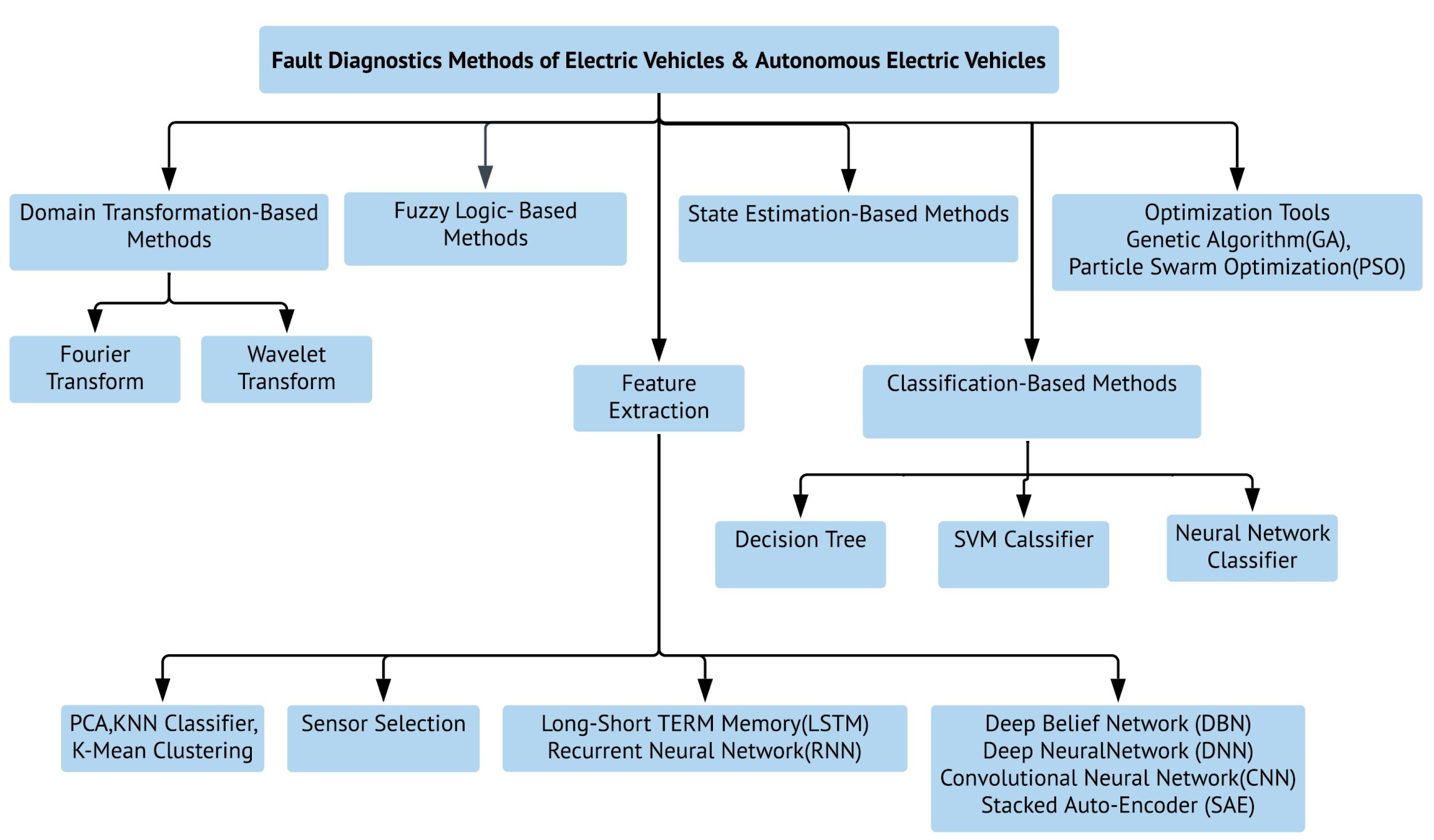
Figure 1 illustrates the FD methods which have been a hot topic [
21] around the world. As mentioned in [
22], the results of the FD can provide many benefits and save costs. Because the number of EVs in smart cities is increasing, researchers are being motivated to discover new better FD methods for EVs as a necessity to securely analyze EVs and operate them.
FD is a fundamental subject for the operation of EVs in the context of a smart city. The main type of AI-based models, artificial neural networks (ANNs), is commonly used in control systems, especially nonlinear control applications because of their incredible learning ability. The ANN training process can be done during an iterative algorithm consisting of a complicated equation to calculate the output values depending on the given sets of the input values. The learning process means updating and determining the synaptic weights. Because of the self-learning ability, ANNs can build a relationship between the inputs and outputs from historical data. Moreover, there are different connection styles and learning algorithms. Several architectures and algorithms have been proposed to solve different problems in nonlinear systems [
23]. In [
24], an ANN is implemented for an EV monitoring system. The FD protects EVs from damage caused by voltage and current instability [
25]. The ANN and space vector machine (SVM) classifier are also used in monitoring and fault identification of a three-phase induction motor [
16,
26,
27].
ML methods are utilized in learning functional relationships between the data [
28]. Deep learning has attracted a great deal of attention in recent years due to its outstanding performance in many fields like image processing, speech recognition, and pattern recognition [
29,
30]. Deep learning, which is one of the ML techniques, has recently showed remarkable results in a variety of fields. The main concept in deep learning algorithms is to automate the mining of data representations [
23]. Deep learning methods extract meaningful features by using a huge amount of unsupervised data. Deep learning is a collection of simple trainable mathematical units that learns complex functions [
29]. This architecture improves ANNs with better training methods; it makes learning algorithms much easier to show better performance. Feature representation attempts to learn good features automatically. Deep learning can learn multiple levels of representation. These algorithms are enhanced by AI which aims to imitate the human’s brain ability to analyze, learn, and make decisions on very complex problems like EVs and smart grids. For the FD, there must be signs of the critical fault occasion. Abrupt voltage and current changes can be regarded as some signs of faults. Meanwhile, some faults have no signs, so they are hard to be predicted. Most of the faults which have signs could possibly be detected by deep-learning-based FD approaches. EVs usually have an induction motor which often gives overload faults. However, under constant-load conditions, the fault monitoring in the induction motor using digital signal processors (DSPs) gives excellent results, while they cannot perform efficiently enough when the load is varied [
31]. The parameters are time-varying in FD approaches of EVs, and so designers tend to model parameter estimators with deep algorithms. This paper will use the long short-term memory (LSTM) network, which is a deep learning approach for the FD of EVs.
3. Problem Statement
EVs usually contain a three-phase inductor motor as a vital part of their configuration. The three-phase induction motors are the most commonly used motors because they have certain advantages such as reliability and low cost. There are two categories of faults in EVs: electrical faults and mechanical ones. Timely detection and accurate FD is essential to the efficient operation of the induction motors in EVs. Also, simultaneous faults in the induction motors can lead to extreme interruptions and losses.
AI techniques such as ANN, SVM, and fuzzy systems are known as attractive alternatives to traditional hard computing methods that cannot easily diagnose different faults in the induction motors. In addition, traditional methods require long computational times. Therefore, an AI model based on expert systems, ANN, and fuzzy logic is used to solve this problem [
32]. FD has proven to be a complex problem because of non-linearity. This problem cannot be solved by using a simple analytical formulation. The FD must have advanced data analytics and deep learning tools to decrease the cost of maintenance and instabilities. The FD in EVs with AI techniques have proved to be a useful tool to solve these issues. Nowadays, the most widely used methods are deep learning approaches. They are appropriate for the problem of energy-related fields [
33].
In this paper, an FD approach with the experimental results of an EV prototype is proposed and the use of deep learning to perform the automated FD is discussed. An EV is simulated and the collect data, that may be related to faults such as voltages, currents, phase angles, and so on, is analyzed. It is inserted into the simulation to obtain faulty data to train the model. In addition, an LSTM model that provides the FD for a fault is developed. The model will be tested by comparing the actual outputs of the simulation. The accuracy of the proposed model will be compared to an ANN to present how the deep learning provides the FD.
4. Methods
As an experimental part of this research study, two induction motors supplied by inverters are integrated into the EV. Pulse width modulation (PWM) is commonly used in the power electronic converters of EVs [
13,
34,
35]. A space vector pulse width modulation (SVPWM) control is applied in this system. The SVPWM is a more sophisticated technique to provide a higher voltage to the induction motor than a classical sine pulse width modulation. The SVPWM uses the eight fundamental voltage vectors to realize the variable frequency of voltage and speed adjustment, and it offers better DC bus utilization.
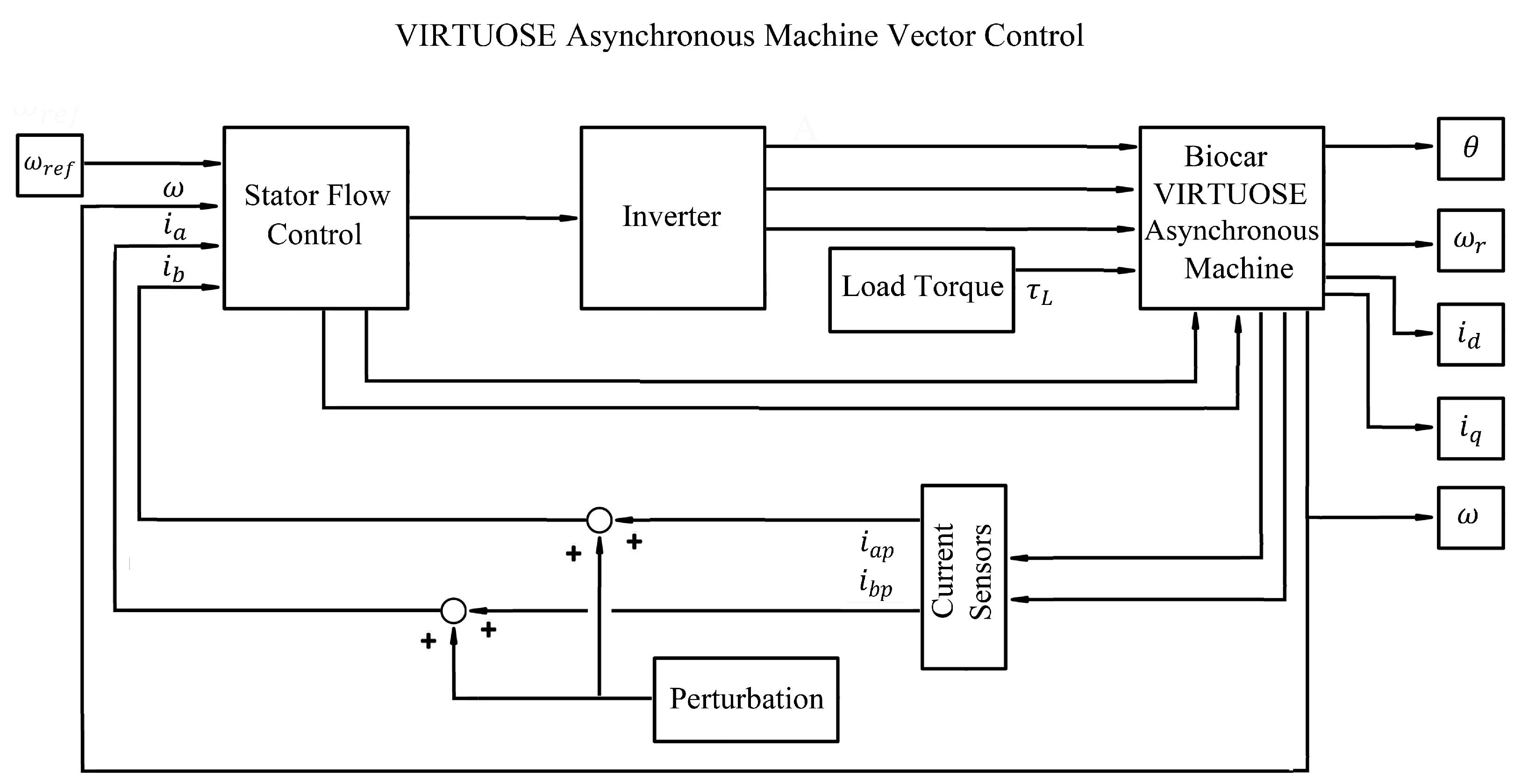
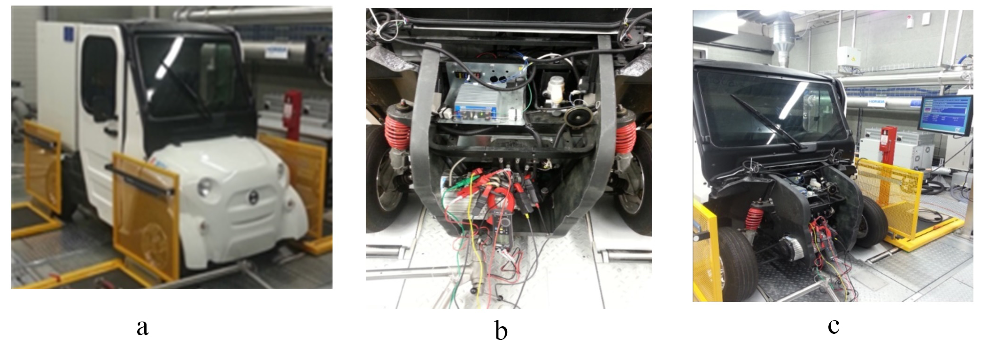
Figure 2 shows the EV prototype test bench.
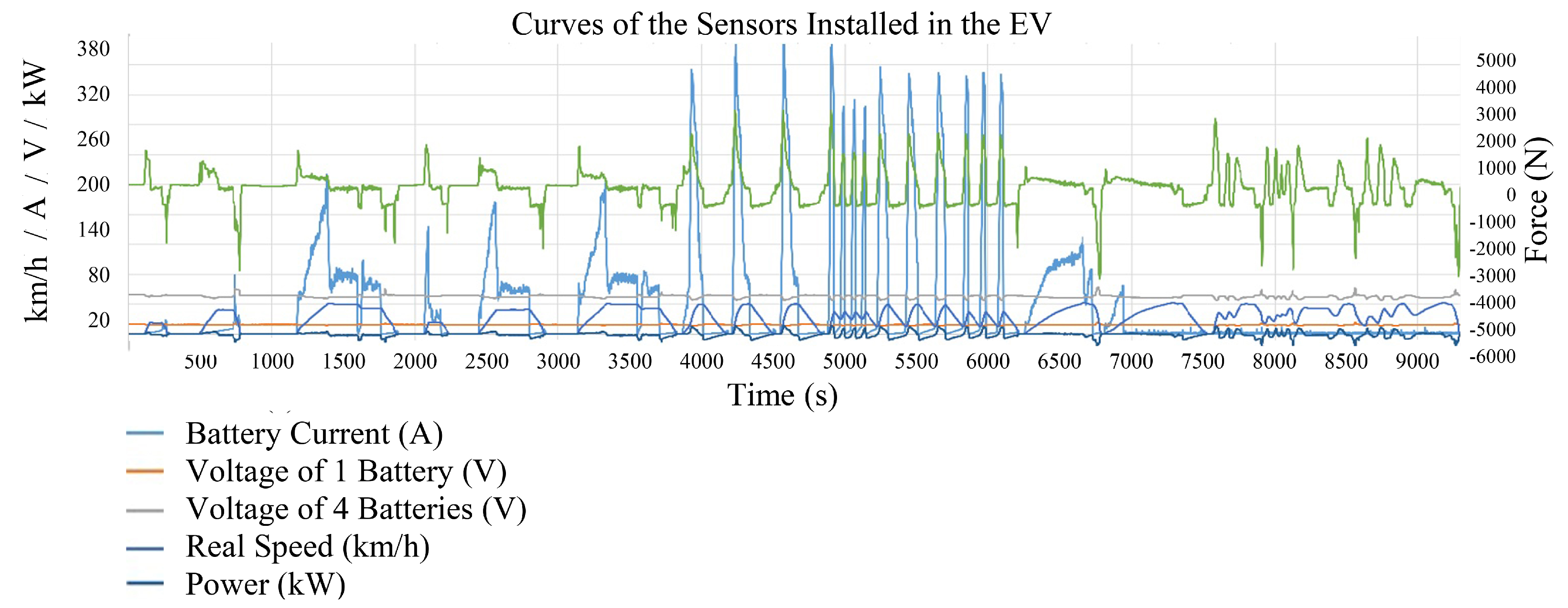
Figure 3 presents the data of the different sensors, current, voltage, and speed sensors, for different driving cycles. The FD approach provides the detection of any type of failure for the electrical components in this EV shown in
Figure 2.
The phase voltages can be expressed in terms of Fourier coefficients:
is the phase angle in radian,
is the angular frequency of the waveform in radian per second, and
is the amplitude of the waveform. The line-to-neutral voltages (
,
,
) may be calculated directly from the line-to-ground voltages (
,
,
). The phase-to-neutral voltages can be expressed as follows:
The voltages of the inverter can also be presented in the d-q reference frame:
The characteristics of the electric motor and the inverter used in modeling and the simulation results have been brought up in the
Table 1.
The practical tests of the engine of the EV made it possible to obtain the engine parameters which have given in
Table 2.
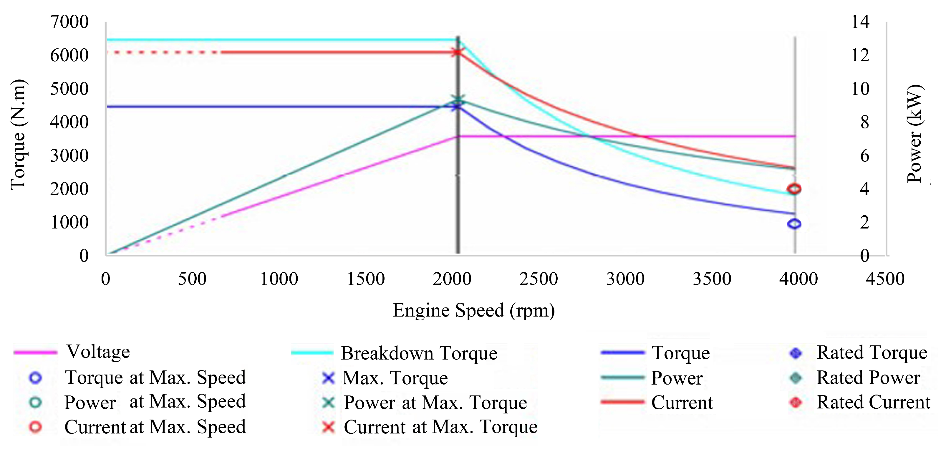
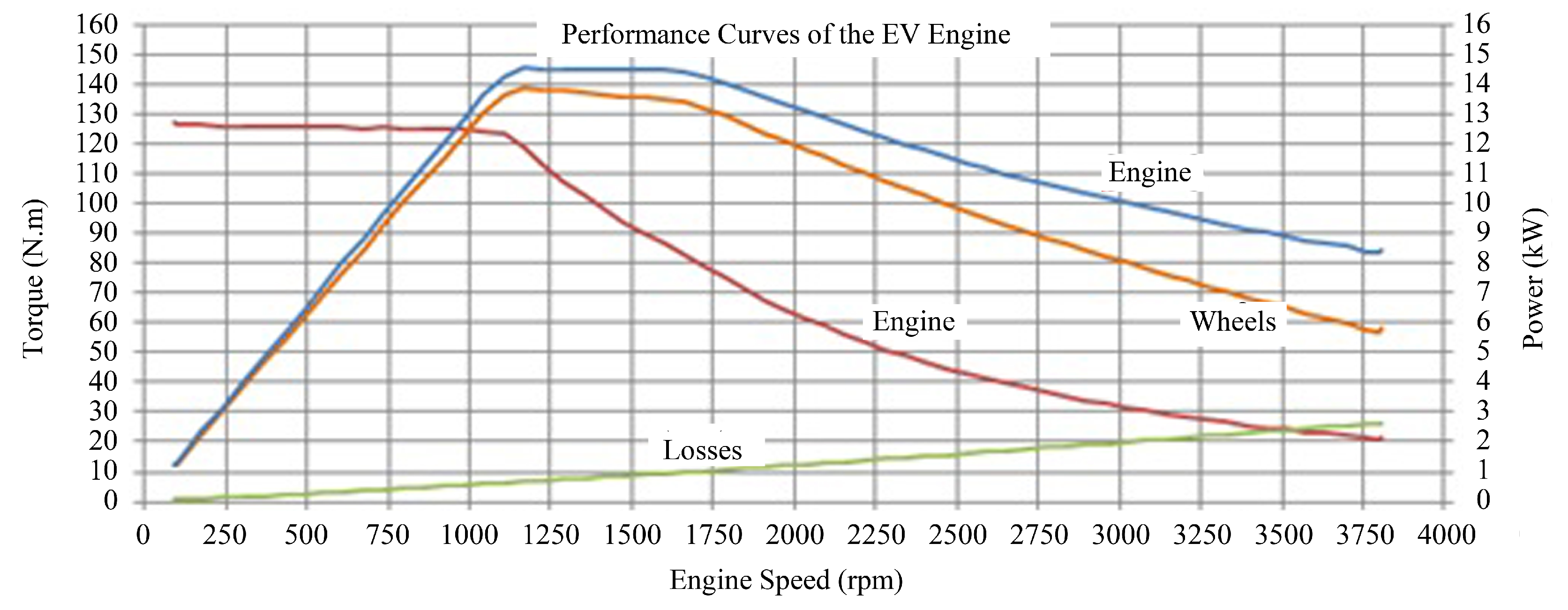
The characteristic curves provided by the manufacturer at the output of the electric motor are illustrated in
Figure 4. These characteristics are used in the simulation. This allows us to apply the FD method in a real context. With deep learning and data analytics, monitoring can be more effective for maintenance. Data analytics is the computational procedure for determining the relations between variables using methods such as database, clustering, ML, regression, and classification. However, because of the numerous sources, the collected data sets might be of different levels of quality in terms of redundancy and consistency. The application of data analytics in EVs aims to extract useful knowledge from sensor data that can be used for FD of EVs. In this part, a data-based FD model will be introduced in the form of simulation. The data set used to train the network is acquired from the simulation of the EV. Voltage and current measurements for both correct and faulty conditions are done. At the first step, large amounts of the data collected from sensors are reshaped to train and test our model. A data set consists of 150,000 current or voltage samples for each type of disturbance. The number of the data sets reaches 600,000. Eighty percent of the data sets are used as training sets. The next step is to develop a model using deep learning technique that is suitable for feature extraction from stored data. The created model can be tested by comparing the real-time measurements and the outputs of the model. The successful model provides crucial information to overcome FD problems of the EV.
Figure 5 shows the flow chart of the FD method.
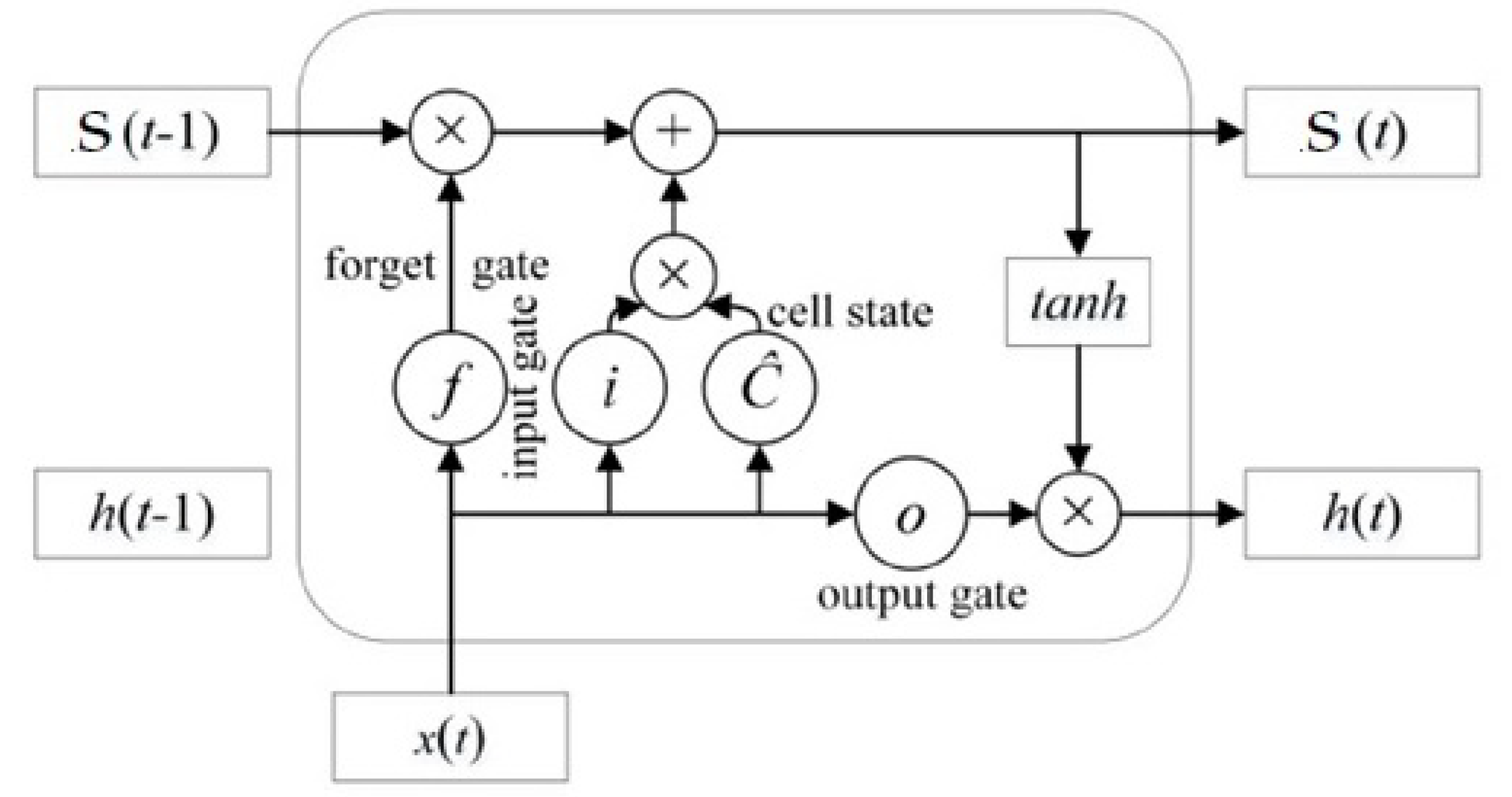
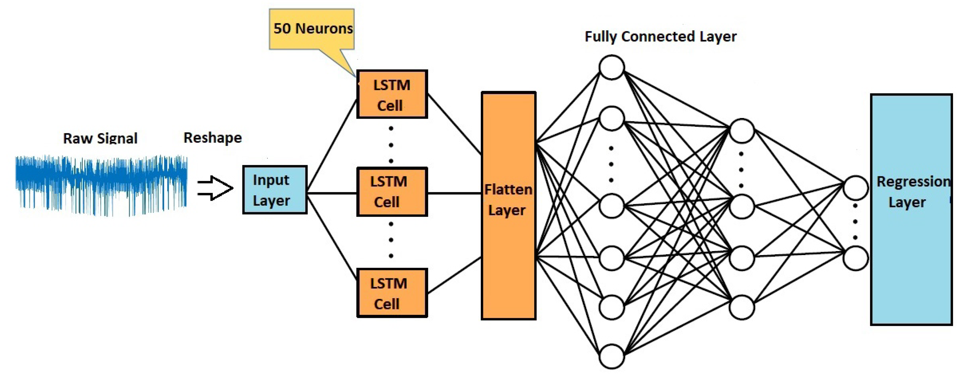
An LSTM network is composed of memory blocks called cells. It has two states: the cell states and the hidden states. The states are transferred between the cells. The cell state is the main chain of the data flow. As previously mentioned, a ML architecture like the LSTM network, which is a deep-learning-based model, and an ANN is designed by means of Matlab software.
Figure 6 illustrates the basic structure of the LSTM model for the FD design of EVs. The LSTM network can solve long-term and short-term dependency problems.
Figure 7 shows the layers of the LSTM. The hidden layer of the LSTM is called a memory cell which is the fundamental part of the LSTM [
36]. There are three gates: input gates, output gates, and forget gates. The input gate defines which inputs will be kept in the next state. The forget gate decides which of the previous state information is not saved. These two gates allow the states to be updated and the information to be added to or to be removed from the memory cell. The LSTM updates the state of the cell to calculate the best output of the LSTM network. This updating process improves the accuracy of the network. Finally, the output gate defines which information in the new state will be the output of the cell. The output of the hidden layers of the LSTM at the time
t is mathematically described as:
The structures of the LSTM are presented in
Figure 6 where
,
,
, and
represent the input gate, forget gate, output gate, and output of the input cell, respectively;
,
,
, and
represent the weights of the input data of
for the input gate, forget gate, output gate, and input cell, respectively;
,
,
, and
denote the weights of the previous output (
) of the hidden layer of the LSTM;
,
,
, and
are the input gates, forget gates, output gates, and input cell bias vectors, respectively;
is the cell input;
and
are the current cell states at the times
t and
;
refers to the output of the current hidden state;
is the sigmoidal function; ⊗ is the element-wise multiplication; and eventually tanh is the hyperbolic tangent function.
It is crucial to properly select the algorithm parameters affecting the training performance [
37]. The learning rate is a key parameter for LSTM networks. It affects the error convergence and the modification of the network’s weights. After comparing the results, the learning rate was determined to be
. After numerous parameters were applied to the LSTM model to find the optimal one, the LSTM model was built with 50 neurons for the FD of the EV. The dropout layer was used to prevent over-fitting. The probability of the dropout layer was set at
which was a default for training. Different epochs like 100, 250, and 500 were tested. The errors during training were obtained:
(12 min),
(35 min), and
(61 min). When the epochs were set bigger than 100, the training times were extremely increased, but the accuracy of the model did not increase very much. Thus, the epochs of training were adjusted at 100. Model parameters were set as shown in
Table 2 and
Table 3. After training, the faulty and correct data sets obtained from the EV simulation were employed to validate the trained LSTM model.
As presented in
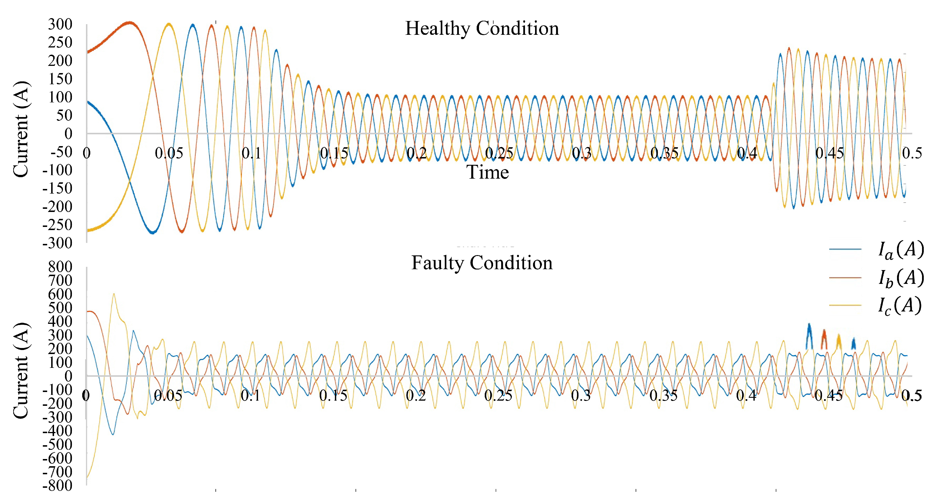
Figure 8, an EV based on an electromechanical conversion chain is regarded as the power system model in this paper. Several faults are inserted into the system to validate the system’s performance. The discrete time and continuous voltages and currents of the simulation are delivered to the FD analysis. The most commonly used parameters are currents and voltages in the FD. Electrical faults in EVs can be classified as open-circuit and short-circuit faults. These faults can be identified by monitoring and diagnosing each phase voltage and currents [
38]. Abnormal voltage changes may lead to open-circuit faults, and abnormal current changes may lead to a short-circuit fault. Line-to-ground (LG) and line-to-line (LL) faults may also occur. The more different faults can be simulated to have larger data-sets which certainly improve the performance of the FD model.
As depicted in
Figure 9, a technique using both correct and faulty conditions of the currents and voltages has been developed. The outputs of the LSTM are used to show the fault occurrences. This approach gives data from current and voltage examinations in the EV to accomplish the FD with the LSTM concept. The Matlab-based LSTM technique has achieved higher diagnostic accuracy in detecting faults in the EV. Faults are inserted into a Simulink model by creating short-circuit and open-circuit faults. A circuit breaker is used to create them. The current and voltage outputs of the proposed Simulink model are used to make a data set for the proposed LSTM architecture. To illustrate how deep learning architectures enhance the performance of the FD, a shallow ANN has been implemented as well.
5. Results
In this paper, the characteristics of the inverter plus the electric motor have been measured and validated so as to compare the results with those given by the manufacturer. To reach such a purpose, a vehicle dyno-roll bench test has been employed as shown in
Figure 2. A vehicle dyno-roller bench makes it possible to determine the output power of the engines by measuring the power at the wheels and the losses in the vehicle transmissions. By knowing the power and the rotation frequency of the electric motors (transmission ratio), it is feasible to calculate their torque. The power measurement is carried out for a speed ramp of 30 s in the iso-speed mode of the dynamometer under full load (accelerator
). The EV has two electric motors: a front electric motor and a rear electric motor. Several tests on this EV have been carried out to compare them to the specifications given by the manufacturer in
Figure 4. The overall characteristics of the two engines in the measurements have been presented in
Figure 10.
As depicted in the figures, the results given by the manufacturer match those of the tests. Moreover, the different sensors connected to the EV provide different curves for the different driving cycles. These curves have been recorded in the vehicle microcomputer, and then anomalies in the different driving cycles can be detected. Neural-network-based FD methods, stochastic deep learning techniques, and deep architectures provide a multi-directional connection between neurons and are expected to increase the accuracy. Based on the available data and by designing FD methods based on deep learning, the FD architectures can be enhanced. To check the performance of the models, as illustrated in
Table 4, a error calculation index like MAPE can be defined.
and
are the actual and predicted outputs.
The better performance of the LSTM compared to traditional networks like ANNs has been revealed. As shown in
Table 5, the MAPE is
when the LSTM is used and the MAPE is
when the ANN is used. The prediction accuracy is improved in comparison with the ANN due to the feature extraction and the characteristics of the deep learning approach.
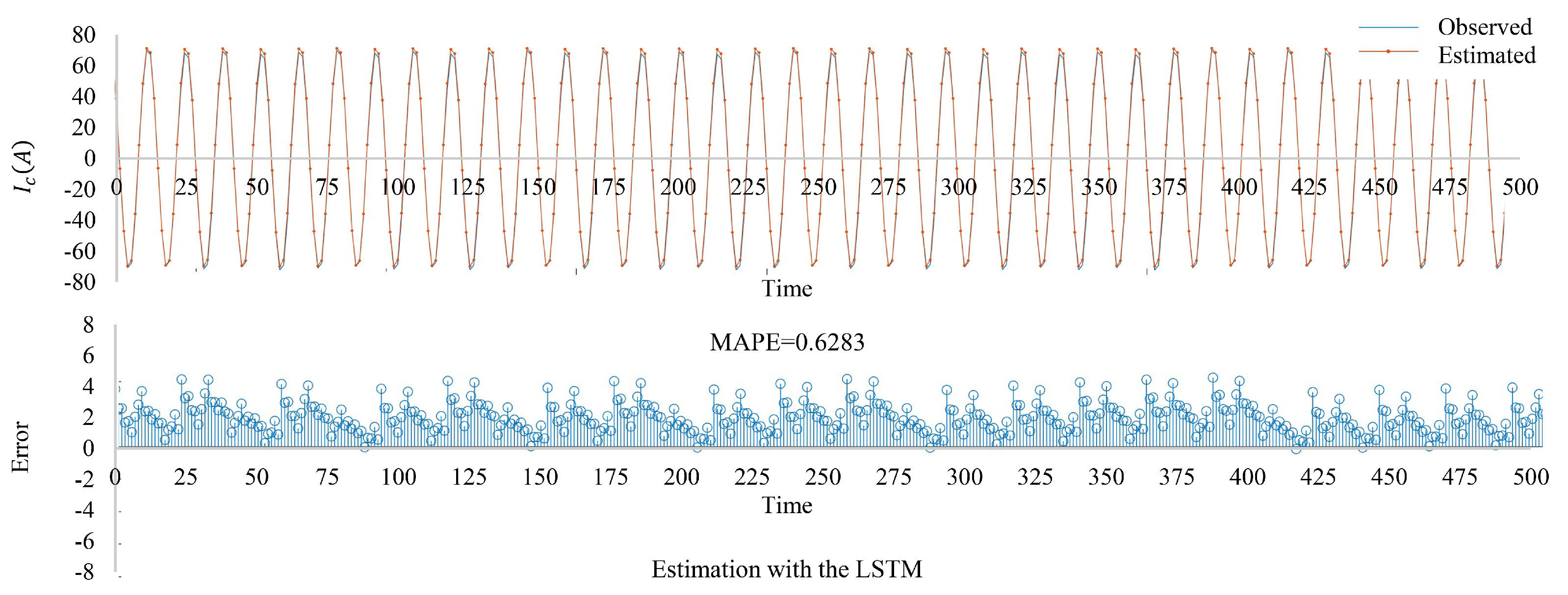
Figure 11 illustrates the FD using the LSTM network. EVs can be operated more securely and reliably when accurate results are obtained.
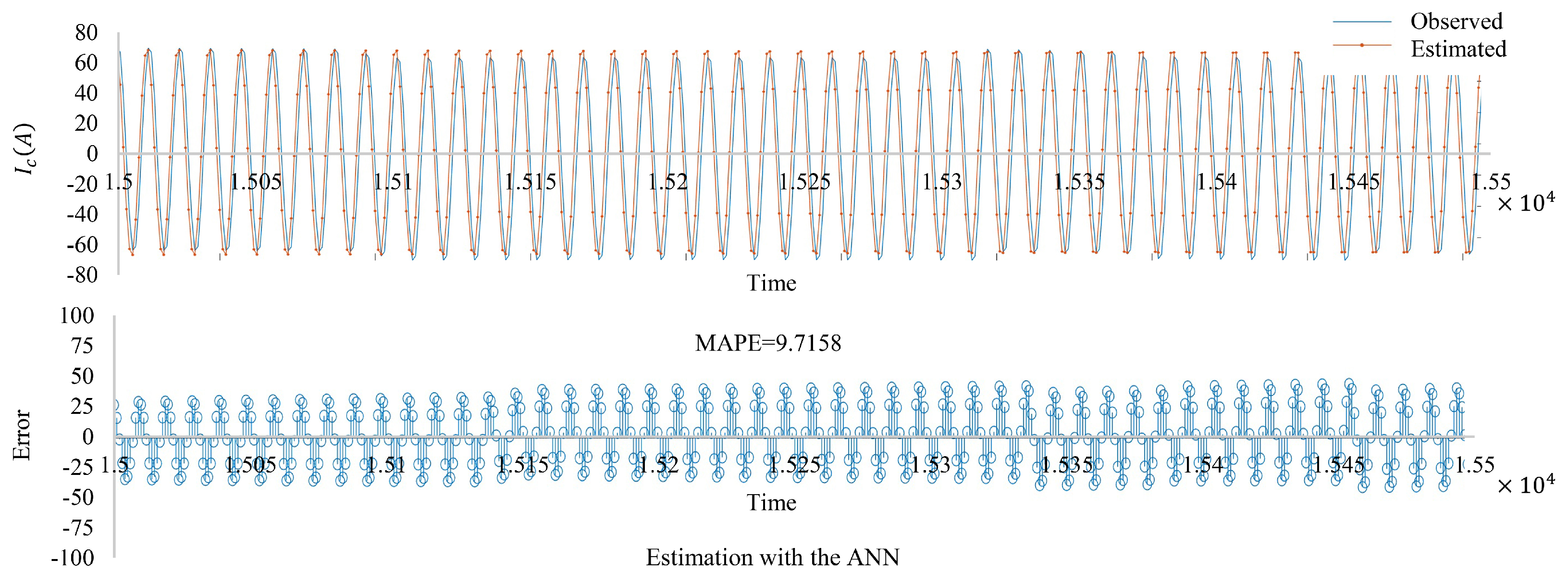
An ANN with 10 layers and 50 neurons per layer has been used. The sigmoid activation function was selected for it. As shown in
Figure 12, the errors for the results are the lowest with an accuracy of 90.29% in terms of MAPE. The differences between the observed and predicted data can be easily noticed in
Figure 12. The ANN is less effective in modeling and has computational problems such as slow convergence and local minimum which cause low accuracy as against the LSTM. The high accuracy achieved by the LSTM model is due to its capability to detect time-series data which are natural in the EVs’ data sets. The LSTM network controls the instantaneous information impact on the sensor data by adding memory cells helping the network save and transmit information over a long period of time. Unlike traditional models, the proposed LSTM network can achieve better performance because of the two-dimensional network which is composed of many memory units. A comparison with other models clearly shows that the proposed LSTM network can be employed with higher performance. Because FD in EVs can be viewed as a time-series problem, the LSTM network, that can update the states, has been suggested. Deep learning methods can successfully simulate highly nonlinear time series such as structured or unstructured output prediction. One of the novelties in this paper is that the LSTM architecture for the FD problem in EVs has been used. In
Table 6, the performance of the proposed LSTM model is compared with the previous studies. It shows the proposed model improves the FD performance.


